LS1 Tuning Info
25
PCM Tuning Process Flow 1. DISABLE ALL TORQUE MANAGEMENT – This will eliminate all torque management within the PCM. Ignore this step for a standard transmission (M6) and continue to step 2. A. Open the VCM Editor>Edit>Transmission>Torque Management B. Set Abuse Mode Enable = False C. Set Abuse Mode RPM, Abuse Mode TPS and Abuse Mode Speed = 0 D. Select>Abuse Mode Torque Reduction vs. RPM. Set all values = 0 2. LTFT TUNING – A. In the VCM Editor>Edit>Engine Diagnostics>Gener al>MAF Sensor Fail Frequency = 0. This will set a P0103 code and turn on the SES light. Ensure that the P0103 DTC is enabled and you are seeing P0103 in the DTC list. Don’t worry about the DTC at this time. B. In the VCM Editor>Edit>Engine>Spar k Advance>Main Spark vs. Airflow vs. RPM Open Throttle/Moving. Copy the High Octane table to the Low Octane table. The computer reverts to the low octane table when a MAF failure is indicated, this will assure optimal timing. C. Start the VCM scanner>Histogram display. File>Connect. Then Tools>VCM Controls>Fue l & Spark>Fuel Trim Learn>Reset Fuel Trims. D. Changes to the LTFT’s do not take effect immediately – the PCM requires about 50 minutes or roughly 100 miles to all ow for the PCM to relearn the fuel curve. Try not to enter PE mode while driving and l ogging for this procedure. Log about 30 minutes of driving at many different speeds and conditions. Try to hit as many cells in the histogram as possible. Stop logging and save the log. Do NOT turn off the engine until the log is saved or i t will be lost. Go to VCM Scanner>Histogram display>LTFT's. Open the VCM Editor>Edit>Engine>Airflow>Main VE and select Primary VE vs. RPM vs. MAP. E. The goal is to get ALL LTFT’s between -5 and +5. Positive LTFT's indicate fuel is being added because of a lean condition. Richen this cell by increasing the VE table value by the amount of the LTFT value. The operation is opposite for negative LTFT's. If LTFT = (4), VE cell value is 67, result would be (67) + (4) =71 - increasing the VE, which is adding fuel. If the LTFT was (-4), the result would be (67) + (-4) =63, decreasing VE and thus reducing fuel. To decrease LTFT values, a smaller number or number closer to zero, ADD the difference between the positive LTFT value and zero to the corresponding cell in the VCM Editor>Edit>Engine>Airflow>Main VE>Primary VE vs. RPM vs. MAP table. To increase a LTFT value, a larger number or number farther away from zero, SUBTRACT the difference between the LTFT value and zero and SUBTRACT
Transcript of LS1 Tuning Info

7/27/2019 LS1 Tuning Info
http://slidepdf.com/reader/full/ls1-tuning-info 1/25
PCM Tuning Process Flow
1. DISABLE ALL TORQUE MANAGEMENT – This will eliminate all torque management
within the PCM. Ignore this step for a standard transmission (M6) and continue to step
2.
A. Open the VCM Editor>Edit>Transmission>Torque ManagementB. Set Abuse Mode Enable = False
C. Set Abuse Mode RPM, Abuse Mode TPS and Abuse Mode Speed = 0
D. Select>Abuse Mode Torque Reduction vs. RPM. Set all values = 0
2. LTFT TUNING –
A. In the VCM Editor>Edit>Engine Diagnostics>General>MAF Sensor Fail Frequency =
0. This will set a P0103 code and turn on the SES light. Ensure that the P0103 DTC is
enabled and you are seeing P0103 in the DTC list. Don’t worry about the DTC at this
time.
B. In the VCM Editor>Edit>Engine>Spark Advance>Main Spark vs. Airflow vs. RPM
Open Throttle/Moving. Copy the High Octane table to the Low Octane table. The
computer reverts to the low octane table when a MAF failure is indicated, this will assure
optimal timing.
C. Start the VCM scanner>Histogram display. File>Connect. Then Tools>VCM
Controls>Fuel & Spark>Fuel Trim Learn>Reset Fuel Trims.
D. Changes to the LTFT’s do not take effect immediately – the PCM requires about 50
minutes or roughly 100 miles to allow for the PCM to relearn the fuel curve. Try not toenter PE mode while driving and logging for this procedure. Log about 30 minutes of
driving at many different speeds and conditions. Try to hit as many cells in the
histogram as possible. Stop logging and save the log. Do NOT turn off the engine until
the log is saved or it will be lost. Go to VCM Scanner>Histogram display>LTFT's. Open
the VCM Editor>Edit>Engine>Airflow>Main VE and select Primary VE vs. RPM vs. MAP.
E. The goal is to get ALL LTFT’s between -5 and +5. Positive LTFT's indicate fuel is being
added because of a lean condition. Richen this cell by increasing the VE table value by
the amount of the LTFT value. The operation is opposite for negative LTFT's.
If LTFT = (4), VE cell value is 67, result would be (67) + (4) =71 - increasing the VE,
which is adding fuel. If the LTFT was (-4), the result would be (67) + (-4) =63,
decreasing VE and thus reducing fuel. To decrease LTFT values, a smaller number or
number closer to zero, ADD the difference between the positive LTFT value and zero to
the corresponding cell in the VCM Editor>Edit>Engine>Airflow>Main VE>Primary VE vs.
RPM vs. MAP table. To increase a LTFT value, a larger number or number farther away
from zero, SUBTRACT the difference between the LTFT value and zero and SUBTRACT
7/27/2019 LS1 Tuning Info
http://slidepdf.com/reader/full/ls1-tuning-info 2/25
from the corresponding cell in the VCM Editor>Edit>Engine>Airflow>Main VE>Primary
VE vs. RPM vs. MAP table. For example, In the VCM Scanner>Histogram display, the (.8,
40) cell, 800 RPM's and 40 kPa, is 4. To bring the VCM Scanner>Histogram
display>LTFT cell (.8, 4.0) DOWN to 0 from 4 ADD 4 to the (.8, 4.0) cell in the VCM
Editor>Edit>Engine>Airflow>Main VE>Primary VE vs. RPM vs. MAP table. If the VCM
Scanner>Histogram display>LTFT cell (2.0, 30) is -10, SUBTRACT 10 from the (2000,
30) cell in the VCM Editor>Edit>Engine>Airflow>Main VE>Primary VE vs. RPM vs. MAP
table to bring it UP to 0. This will not work out exactly but will be VERY CLOSE.
F. Repeat steps D-F until ALL values in the VCM Scanner>Histogram display>LTFT are
between -5 and +5. Try to complete this on the same day for best results as LTFT
values can vary +-4% per day.
G. Once all values are between -5 and +5, look at the VCM
Editor>Edit>Engine>Airflow>Main VE>Primary VE vs. RPM vs. MAP>3D Surface graph.
If the 3D Surface graph looks choppy, click on polynomial smoothing ONCE. This willsmooth out the table values and provide a crisper throttle response. The table can also
be hand smoothed using the 3D graph. Look for spikes in the table and
increase/decrease the cells around the spike, creating a smooth table. Now rescan, and
go back to step E.
3. WOT PE TUNING – Do this only AFTER all LTFT's are -5 to +5. This method uses the
stock narrow band oxygen sensors which are not accurate for this type of tuning.
A. Open the VCM scanner, do not worry about resetting the fuel trims they should be
learned at this point. If not, it takes roughly 100 miles or 50 minutes of driving to set
the LTFT's.
B. Open the VCM Scanner>Histogram display and do a nice 0-70 or preferable 0-
100mph run. Look at knock retard FIRST. If knock retard is present, skip to section 4. If
knock retard is not present, continue to the step C.
C. Open the VCM Scanner>Histogram display>Air/Fuel tab and look at the 100(kPa)
row. Most cars seem to like narrow band oxygen sensor reading between 890mv -
900mv.
D. For example, at 100(kPa), 3200(RPM) the narrow band oxygen sensors are at
950mv. We want to bring that down to 890mv. Go to the VCM Editor
Engine>Fuel>Power Enrich, PE Enrichment>V8 Molt. vs. RPM. Make sure Plus and
Selected are bubbled in. In this case the narrow band oxygen sensor is reading rich, so
bring it down by SUBTRACTING .01. NOTICE THE DECIMAL!!!! VERY IMPORTANT!!! If
lean, BELOW 890mv then ADD .01 at a time. This is a small increment but we do not
want to hurt the motor.
7/27/2019 LS1 Tuning Info
http://slidepdf.com/reader/full/ls1-tuning-info 3/25
E. After making the changes, go back to step B and repeat until the oxygen sensors are
in the 890mv to 900mv range.
4. ELIMINATING KNOCK RETARD -
A. In the VCM Scanner>Histogram display>Retard, look for ANY knock retard. For
example, cell (4.0, .20) shows 4 degrees of knock retard. This should be 0, so
SUBTRACT 4 from the VCM Editor>Edit>Engine>Spark Advance>Main Spark vs. Airflow
vs. RPM Open Throttle/Moving>High Octane (4000, .20) cell. Values cannot be less than
zero in this table.
B. In the VCM Editor>Edit>Engine>Spark Advance>Main Spark vs. Airflow vs. RPM
Open Throttle/Moving>High Octane, go to the (4000, .20) cell AND/OR whatever other
cells that have knock retard and SUBTRACT the amount of knock retard that is present
in the Histogram display from the value that is in the corresponding cell in the VCM
Editor>Edit>Engine>Spark Advance>Main Spark vs. Airflow vs. RPM OpenThrottle/Moving>High Octane table. Subtract by simply clicking on the Plus selection and
in the box type -4 or whatever number you have to subtract by and click commit.
C. Scan again and verify NO knock retard is present. If still present, repeat from step A.
5. A4 TRANSMISSION SETTINGS -
A. Ensure all Torque Management is disabled. If not, see Section 1.
B. Open the VCM Editor>Edit>Transmission>A4 Shift Speed. Set WOT Shift Enable
%TPS = 90.
C. Set WOT Shift Disable %TPS = WOT Shift Enable %TPS-10 or 80 if you used the
parameter in step B.
D. Look at VCM Editor>Edit>Transmission>WOT Shift RPM vs. Shift. Set these table
parameters to the desired WOT shift RPM for each gear. Keep in mind there is a slight
delay at the shift point that will cause the engine to exceed these RPM settings. Ensure
the VCM Editor>Edit>Engine>Fuel Control>Fuel Cutoff, DFCO>RPM Limits>P/N Cutoff
RPM is roughly 500 RPM higher than these settings. We don’t want to hit the rev limiter
during the WOT shift. Set Normal, Performance, and Hot tables to the same parameters.
E. VCM Editor>Edit>Transmission>WOT Shift Speed vs. Shift--PLEASE PROVIDE ME
WITH A GOOD LINK FOR THIS. I KNOW THERE ARE TABLES/CALCULATORS PER GEAR
OUT THERE.
F. VCM Editor>Edit>Transmission>Shift Speed vs. %TPS vs. Shift = Leave stock
parameters.
G. Go to VCM Editor>Edit>Transmission>A4 Shift Properties>Desired Shift Time vs.
Torque>Normal. I basically guessed here, and could use some input. For the first half of
7/27/2019 LS1 Tuning Info
http://slidepdf.com/reader/full/ls1-tuning-info 4/25
the torque band, I set shift time to .500 so you get nice soft, smooth shifts. Starting
about midway, I decreased to .250 and for last 1/4 I changed to .100. I heard you do
not want to go below .100 or else you will run into some kind of gear crossing? Please
feel free to fill in here.
H. Go to VCM Editor>Edit>Transmission>Base Shift Pressure vs. Torque vs. Gear. Okay
this is kind of weird and I don't understand it, but what I PERSONALLY did was again
take half of the chart and to the left. Take this and set to a LOW # like 10. I have a
shift kit in my car, and setting first half gives me nice smooth shifts. You would never
know I had a shift kit or torque converter in my car. I then took the middle and started
beefing up shifts in increments of 10 then increments of 15. By far right of table I have
shift pressure up to 96. Now, when you drive my car at 0-1/4 throttle it is SMOOTH. 1/2
throttle, you can feel a nice crisp shift. WOT it chirps tires from 1-2 and 2-3 shifts nice
and hard.
I. Upshift/Downshift pressure modifiers - I don't understand. If you do, teach me andI'll update.
J. If you have a shift kit, leave max line pressure at 90. If not you can probably set to
100.
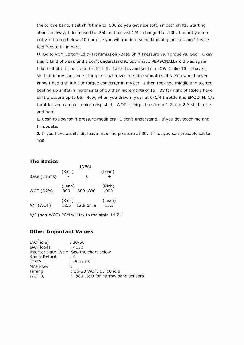
The BasicsIDEAL
(Rich) (Lean)
Base (Ltrims) - 0 +
(Lean) (Rich)
WOT (O2's) .800 .880-.890 .900
(Rich) (Lean)A/F (WOT) 12.5 12.8 or .9 13.3
A/F (non-WOT) PCM will try to maintain 14.7:1
Other Important Values
IAC (idle) : 30-50IAC (load) : <120
Injector Duty Cycle: See the chart belowKnock Retard : 0
LTFT’s : -5 to +5MAF Flow :
Timing : 26-28 WOT, 15-18 idleWOT 02 : .880-.890 for narrow band sensors
7/27/2019 LS1 Tuning Info
http://slidepdf.com/reader/full/ls1-tuning-info 5/25
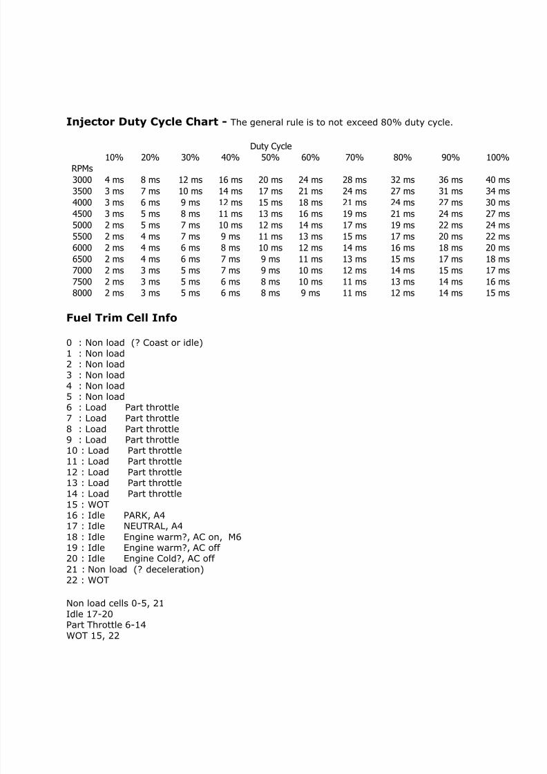
Injector Duty Cycle Chart - The general rule is to not exceed 80% duty cycle. Duty Cycle
10% 20% 30% 40% 50% 60% 70% 80% 90% 100%
RPMs
3000 4 ms 8 ms 12 ms 16 ms 20 ms 24 ms 28 ms 32 ms 36 ms 40 ms
3500 3 ms 7 ms 10 ms 14 ms 17 ms 21 ms 24 ms 27 ms 31 ms 34 ms
4000 3 ms 6 ms 9 ms 12 ms 15 ms 18 ms 21 ms 24 ms 27 ms 30 ms
4500 3 ms 5 ms 8 ms 11 ms 13 ms 16 ms 19 ms 21 ms 24 ms 27 ms
5000 2 ms 5 ms 7 ms 10 ms 12 ms 14 ms 17 ms 19 ms 22 ms 24 ms
5500 2 ms 4 ms 7 ms 9 ms 11 ms 13 ms 15 ms 17 ms 20 ms 22 ms
6000 2 ms 4 ms 6 ms 8 ms 10 ms 12 ms 14 ms 16 ms 18 ms 20 ms
6500 2 ms 4 ms 6 ms 7 ms 9 ms 11 ms 13 ms 15 ms 17 ms 18 ms
7000 2 ms 3 ms 5 ms 7 ms 9 ms 10 ms 12 ms 14 ms 15 ms 17 ms7500 2 ms 3 ms 5 ms 6 ms 8 ms 10 ms 11 ms 13 ms 14 ms 16 ms
8000 2 ms 3 ms 5 ms 6 ms 8 ms 9 ms 11 ms 12 ms 14 ms 15 ms
Fuel Trim Cell Info
0 : Non load (? Coast or idle)
1 : Non load2 : Non load
3 : Non load
4 : Non load5 : Non load
6 : Load Part throttle7 : Load Part throttle
8 : Load Part throttle9 : Load Part throttle10 : Load Part throttle
11 : Load Part throttle
12 : Load Part throttle13 : Load Part throttle
14 : Load Part throttle
15 : WOT16 : Idle PARK, A417 : Idle NEUTRAL, A4
18 : Idle Engine warm?, AC on, M619 : Idle Engine warm?, AC off 20 : Idle Engine Cold?, AC off
21 : Non load (? deceleration)22 : WOT
Non load cells 0-5, 21
Idle 17-20Part Throttle 6-14
WOT 15, 22
7/27/2019 LS1 Tuning Info
http://slidepdf.com/reader/full/ls1-tuning-info 6/25
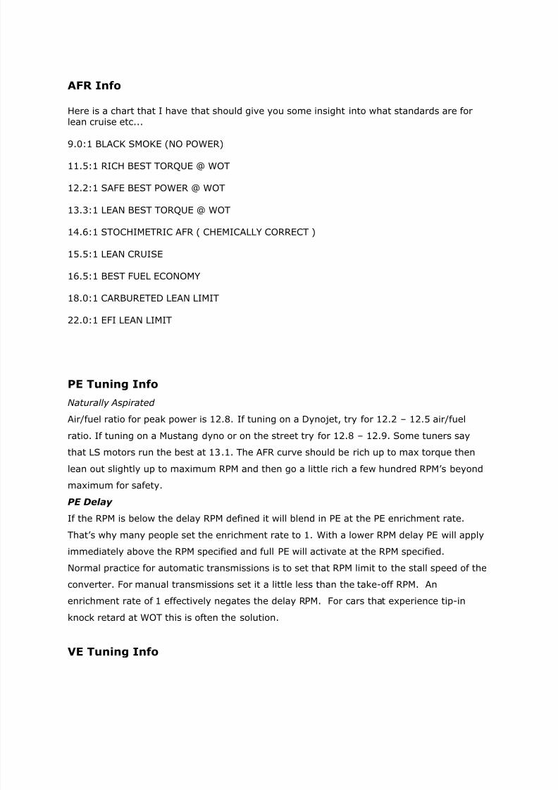
AFR Info
Here is a chart that I have that should give you some insight into what standards are forlean cruise etc...
9.0:1 BLACK SMOKE (NO POWER)
11.5:1 RICH BEST TORQUE @ WOT
12.2:1 SAFE BEST POWER @ WOT
13.3:1 LEAN BEST TORQUE @ WOT
14.6:1 STOCHIMETRIC AFR ( CHEMICALLY CORRECT )
15.5:1 LEAN CRUISE
16.5:1 BEST FUEL ECONOMY
18.0:1 CARBURETED LEAN LIMIT
22.0:1 EFI LEAN LIMIT
PE Tuning Info
Naturally Aspirated
Air/fuel ratio for peak power is 12.8. If tuning on a Dynojet, try for 12.2 – 12.5 air/fuel
ratio. If tuning on a Mustang dyno or on the street try for 12.8 – 12.9. Some tuners say
that LS motors run the best at 13.1. The AFR curve should be rich up to max torque then
lean out slightly up to maximum RPM and then go a little rich a few hundred RPM’s beyond
maximum for safety.
PE Delay
If the RPM is below the delay RPM defined it will blend in PE at the PE enrichment rate.
That’s why many people set the enrichment rate to 1. With a lower RPM delay PE will apply
immediately above the RPM specified and full PE will activate at the RPM specified.Normal practice for automatic transmissions is to set that RPM limit to the stall speed of the
converter. For manual transmissions set it a little less than the take-off RPM. An
enrichment rate of 1 effectively negates the delay RPM. For cars that experience tip-in
knock retard at WOT this is often the solution.
VE Tuning Info
7/27/2019 LS1 Tuning Info
http://slidepdf.com/reader/full/ls1-tuning-info 7/25
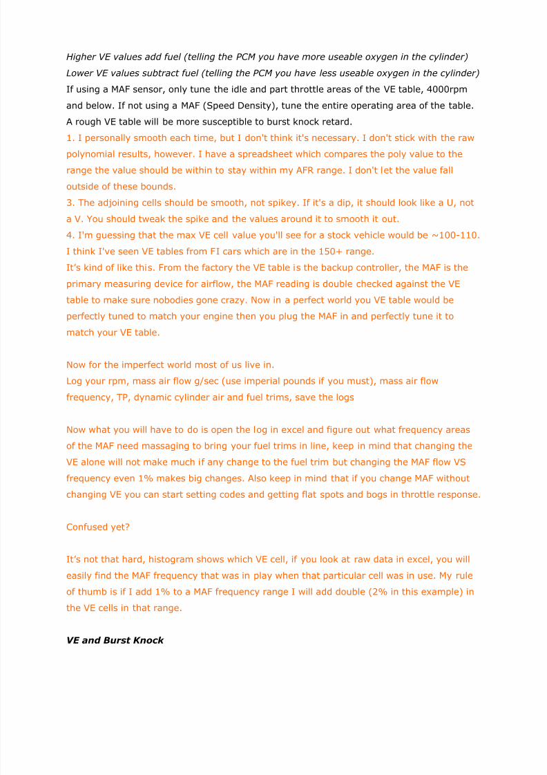
Higher VE values add fuel (telling the PCM you have more useable oxygen in the cylinder)
Lower VE values subtract fuel (telling the PCM you have less useable oxygen in the cylinder)
If using a MAF sensor, only tune the idle and part throttle areas of the VE table, 4000rpm
and below. If not using a MAF (Speed Density), tune the entire operating area of the table.
A rough VE table will be more susceptible to burst knock retard.
1. I personally smooth each time, but I don't think it's necessary. I don't stick with the raw
polynomial results, however. I have a spreadsheet which compares the poly value to the
range the value should be within to stay within my AFR range. I don't let the value fall
outside of these bounds.
3. The adjoining cells should be smooth, not spikey. If it's a dip, it should look like a U, not
a V. You should tweak the spike and the values around it to smooth it out.
4. I'm guessing that the max VE cell value you'll see for a stock vehicle would be ~100-110.
I think I've seen VE tables from FI cars which are in the 150+ range.
It’s kind of like this. From the factory the VE table is the backup controller, the MAF is theprimary measuring device for airflow, the MAF reading is double checked against the VE
table to make sure nobodies gone crazy. Now in a perfect world you VE table would be
perfectly tuned to match your engine then you plug the MAF in and perfectly tune it to
match your VE table.
Now for the imperfect world most of us live in.
Log your rpm, mass air flow g/sec (use imperial pounds if you must), mass air flow
frequency, TP, dynamic cylinder air and fuel trims, save the logs
Now what you will have to do is open the log in excel and figure out what frequency areas
of the MAF need massaging to bring your fuel trims in line, keep in mind that changing the
VE alone will not make much if any change to the fuel trim but changing the MAF flow VS
frequency even 1% makes big changes. Also keep in mind that if you change MAF without
changing VE you can start setting codes and getting flat spots and bogs in throttle response.
Confused yet?
It’s not that hard, histogram shows which VE cell, if you look at raw data in excel, you will
easily find the MAF frequency that was in play when that particular cell was in use. My rule
of thumb is if I add 1% to a MAF frequency range I will add double (2% in this example) in
the VE cells in that range.
VE and Burst Knock

7/27/2019 LS1 Tuning Info
http://slidepdf.com/reader/full/ls1-tuning-info 8/25
Once the VE table is correct, tune out any detected burst knock by increasing the
Edit>Engine>Spark Retard>Burst KR Enable Delta Cyl Air Threshold vs. RPM table. The
ultimate measure is whatever it takes to eliminate the error between commanded and
measured AFR.
SD Tuning, LTFT’s and MAF Table Scaling
Once the MAFless (SD) VE table is correct and the mass air flow sensor is reconnected, the
LTFT’ s will go positive. Now scale the VCM Editor>Edit>Engine>Airflow>MAF
Calibration>MAF Airflow vs. Output Frequency table positive to get the LTFT’ s back to where
they were when it was MAFless (SD). The point is to get an accurate VE table and then
adjust the MAF calibration table to agree with the VE table at the observed LTFT values.
MAF Sensor Info
The stock mass air flow calibration is correct +-4% as long as nothing in the intake tract
has been modified. If the MAF meter, air lid, air intake, or air filter has been modified than
the MAF Airflow vs. Frequency table will need modification. Do this after the VE table has
been corrected.
MAF Tuning – In Work
1.) Make sure you log Dynamic Airflow vs. MAF Frequency (Hz) In HP Tuners it is measured
in lb/min so we will have to convert this later for the MAF table (g/sec).
2.) Go do enough driving to log a variety of MAF frequencies. You probably won't get a
whole lot of data above 10,000 Hz or below 2000 Hz, but get as much as you can. Cruising
on the highway is a good place for this as you can cover all rpms and a wide range of mph.
3.) Save the log run and export the data into an Excel readable format and sort the data by
MAF frequency (smallest to largest).
4.) Section off MAF frequency ranges that register with the frequency points on the MAF
table (i.e. For MAF table freq = 3000, you want to use the data you logged in the range of
2940 to 3065) Take the average of all the Dynamic Airflow data in this range. The reason
you want to use this range is so that the average is calculated using a sort of "swing error"
that straddles the calibration point itself.
5.) Once you have calculated averages for each range (this will be very tedious and take
quite a bit of time, but using excel functions makes it much easier) you will have new MAF
Airflow data to rebuild the table with. 1 lb/min is equal to 7.58 g/sec so do that calculation
and you will derive a new MAF table.
6.) For all the calibration points that you were missing data for (above 10K Hz, below 2K
Hz) you can either shoot in the dark and scale up accordingly, or if you choose to log raw
MAF air readings in tandem with Dynamic Airflow and frequency, you can calculate the
variance b/w your dynamic airflow and MAF airflow and scale up by the trends you see on
either extreme. (i.e. If as you get closer to 10K and you notice the dyn airflow is 10%
7/27/2019 LS1 Tuning Info
http://slidepdf.com/reader/full/ls1-tuning-info 9/25
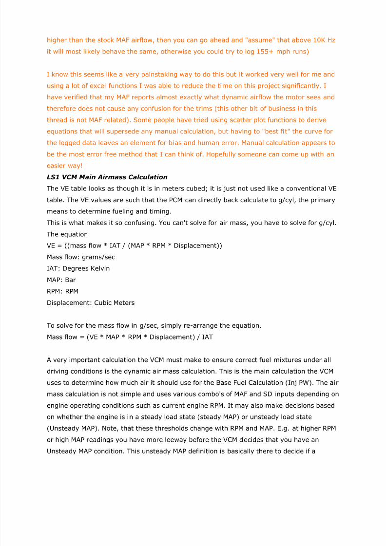
higher than the stock MAF airflow, then you can go ahead and "assume" that above 10K Hz
it will most likely behave the same, otherwise you could try to log 155+ mph runs)
I know this seems like a very painstaking way to do this but it worked very well for me and
using a lot of excel functions I was able to reduce the time on this project significantly. I
have verified that my MAF reports almost exactly what dynamic airflow the motor sees and
therefore does not cause any confusion for the trims (this other bit of business in this
thread is not MAF related). Some people have tried using scatter plot functions to derive
equations that will supersede any manual calculation, but having to "best fit" the curve for
the logged data leaves an element for bias and human error. Manual calculation appears to
be the most error free method that I can think of. Hopefully someone can come up with an
easier way!
LS1 VCM Main Airmass Calculation
The VE table looks as though it is in meters cubed; it is just not used like a conventional VEtable. The VE values are such that the PCM can directly back calculate to g/cyl, the primary
means to determine fueling and timing.
This is what makes it so confusing. You can't solve for air mass, you have to solve for g/cyl.
The equation
VE = ((mass flow * IAT / (MAP * RPM * Displacement))
Mass flow: grams/sec
IAT: Degrees Kelvin
MAP: Bar
RPM: RPM
Displacement: Cubic Meters
To solve for the mass flow in g/sec, simply re-arrange the equation.
Mass flow = (VE * MAP * RPM * Displacement) / IAT
A very important calculation the VCM must make to ensure correct fuel mixtures under all
driving conditions is the dynamic air mass calculation. This is the main calculation the VCM
uses to determine how much air it should use for the Base Fuel Calculation (Inj PW). The air
mass calculation is not simple and uses various combo's of MAF and SD inputs depending on
engine operating conditions such as current engine RPM. It may also make decisions based
on whether the engine is in a steady load state (steady MAP) or unsteady load state
(Unsteady MAP). Note, that these thresholds change with RPM and MAP. E.g. at higher RPM
or high MAP readings you have more leeway before the VCM decides that you have an
Unsteady MAP condition. This unsteady MAP definition is basically there to decide if a

7/27/2019 LS1 Tuning Info
http://slidepdf.com/reader/full/ls1-tuning-info 10/25
throttle transient has occurred (or other) i.e. the MAF input is known not to be accurate
under these operating conditions.
Under normal conditions (i.e. all sensors working properly) in the code I’m looking at it is
like this:
(caveat: many of these thresholds may vary between code revs and vehicle type)
RPM > 4000
----------
trust MAF completely and ignore SD calcs (apart from MAF sanity checking purposes)
RPM < 4000
----------
if RPM < 2400 and MAP < 84 kPa then
Steady MAP threshold = 0.0 kPa
elseSteady MAP threshold = 0.8 kPa
If (Steady MAP) then
Calculate MAF Air mass/SD Air mass ratio (used for Unsteady MAP operation)
Correction Air mass = MAF Air mass (filtered)
else
Correction Air mass = SD Air mass x MAF/SD Air mass Ratio (calculated during Steady
MAP conditions)
Transient Corrected Air mass = previous Final Air mass + proportion of Correction Air
mass
Final Air mass = fn(MAF Airflow, previous MAF Airflow, prev 3 MAP readings, prev 3 TPS
readings,
Transient Corrected Air mass)
There are 9 coefficients to this filter (and a total of up to 16 different sets of coefficients
depending on operating conditions). It is worth noting that the previous value is weighted
heaviest followed by the 2 MAF terms, so MAF dominates IMHO).
There are also a number of checks at the end to make sure things do not exceed certain
limits.
To summarize:
7/27/2019 LS1 Tuning Info
http://slidepdf.com/reader/full/ls1-tuning-info 11/25
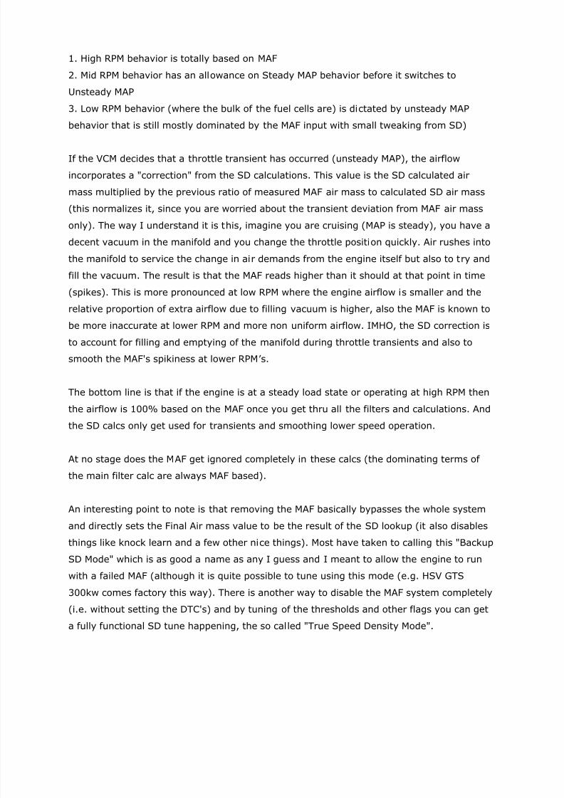
1. High RPM behavior is totally based on MAF
2. Mid RPM behavior has an allowance on Steady MAP behavior before it switches to
Unsteady MAP
3. Low RPM behavior (where the bulk of the fuel cells are) is dictated by unsteady MAP
behavior that is still mostly dominated by the MAF input with small tweaking from SD)
If the VCM decides that a throttle transient has occurred (unsteady MAP), the airflow
incorporates a "correction" from the SD calculations. This value is the SD calculated air
mass multiplied by the previous ratio of measured MAF air mass to calculated SD air mass
(this normalizes it, since you are worried about the transient deviation from MAF air mass
only). The way I understand it is this, imagine you are cruising (MAP is steady), you have a
decent vacuum in the manifold and you change the throttle position quickly. Air rushes into
the manifold to service the change in air demands from the engine itself but also to try and
fill the vacuum. The result is that the MAF reads higher than it should at that point in time(spikes). This is more pronounced at low RPM where the engine airflow is smaller and the
relative proportion of extra airflow due to filling vacuum is higher, also the MAF is known to
be more inaccurate at lower RPM and more non uniform airflow. IMHO, the SD correction is
to account for filling and emptying of the manifold during throttle transients and also to
smooth the MAF's spikiness at lower RPM’ s.
The bottom line is that if the engine is at a steady load state or operating at high RPM then
the airflow is 100% based on the MAF once you get thru all the filters and calculations. And
the SD calcs only get used for transients and smoothing lower speed operation.
At no stage does the MAF get ignored completely in these calcs (the dominating terms of
the main filter calc are always MAF based).
An interesting point to note is that removing the MAF basically bypasses the whole system
and directly sets the Final Air mass value to be the result of the SD lookup (it also disables
things like knock learn and a few other nice things). Most have taken to calling this "Backup
SD Mode" which is as good a name as any I guess and I meant to allow the engine to run
with a failed MAF (although it is quite possible to tune using this mode (e.g. HSV GTS
300kw comes factory this way). There is another way to disable the MAF system completely
(i.e. without setting the DTC's) and by tuning of the thresholds and other flags you can get
a fully functional SD tune happening, the so called "True Speed Density Mode".

7/27/2019 LS1 Tuning Info
http://slidepdf.com/reader/full/ls1-tuning-info 12/25
LTFT and STFT Info
STFT Info
The PCM uses the Short Term Fuel Trim (STFT) for real time fueling corrections. They have
a 10% window that will only affect the Long Term Fuel Trim (LTFT) if the fueling correction
is beyond the 10% window for 10 seconds. If this condition exists, the LTFT is changed and
acted upon during the next PCM timed cycle, which is every 10 minutes.
LTFT Info
The purpose of LTFT’s is to compensate for engine and sensor age and variation over time.
+ LTRIMS, PCM is sensing a lean condition and adding extra fuel
- LTRIMS, PCM is sensing a rich condition and subtracting fuel
Positive long term fuel trims (LTFT's) indicate the PCM is commanding more fuel in order to
compensate for what is being perceived as a lean condition. By doing so it maintains a
stoichiometric air-fuel ratio of 14.7:1 during closed loop operation. That is, less than wide
open throttle.
Negative LTFT's indicate the PCM is commanding less fuel due to what is perceived as a rich
condition although the air-fuel ratio remains the same at 14.7:1 and in reality it's neither
truly lean nor rich.
However, positive LTFT's can result in a rich air-fuel ratio during WOT operation because the
PCM will add fuel in addition to the PE table. If they were negative no fuel is subtracted
during WOT as that could result in a lean condition resulting in detonation.
If the LTFT's are positive, often resulting in a rich AFR during WOT, horsepower may be
gained by getting the LTFT's as close to zero or slightly negative during closed loop. In this
way no additional fuel is added during WOT. If the LTFT's are negative no additional
horsepower can be gained because the AFR at WOT is then determined solely by the power
enrichment table without any additional fuel being added except during CAT over temp
conditions.
To put it simply what's happening is the Mass Airflow Sensor (MAF) is calibrated to expect
outside air temperatures and temperature change rates within a specified range. When you
add an aftermarket intake you often get colder and therefore denser, more oxygen rich air,
than what the MAF is calibrated for. It interprets this as more air than expected when in
reality there really isn't. In turn the PCM tells the injectors to stay open for a longer period
of time by lengthening the Injector Pulse Width in order to inject more fuel into the
combustion chambers. By doing so the air-fuel ratio remains at 14.7 parts of air for every
one part fuel. Hence it is neither lean nor rich but rather right where it's supposed to be.
But, when you go WOT the PCM remembers it had to add additional fuel during closed loop
and adds this extra fuel in addition to a predetermined amount called for in the Power
Enrichment vs. RPM table. This results in a too rich condition at WOT and a loss of
7/27/2019 LS1 Tuning Info
http://slidepdf.com/reader/full/ls1-tuning-info 13/25
horsepower. Or to put it another way: not as much H.P. as you can obtain should that extra
fuel not have been added.
For this reason you want the LTFT's as close to zero or slightly negative during closed loop
so no extra fuel is added during WOT. You do this by using scanning software and a
program such as LS1 Edit, etc. to get the LTFT's correct. Once they are you can then tune
WOT using a wideband O2 meter and typically adjust the PE vs. RPM table for the AFR you
want. Note: some applications such as nitrous or forced induction cars usually require a
richer AFR than a normally aspirated car.
What is closed loop you ask? Closed loop operation means the front O2 sensors (forward of
the catalytic converters) are used to help determine the AFR and offer feedback to the PCM
as to the current AFR. The PCM then adjusts the injector pulse rate to maintain a 14.7:1
AFR. So it's just that, a closed feedback loop.
What does open loop operation mean? Well, instead of using a closed feedback loop (the O2
sensors are not used for input) the PCM uses a lookup table that, to put it simply, is just atable that says "at this RPM use X amount of fuel." This is called the PE vs. RPM table or
"Power Enrichment vs. RPM" table.
Deleting Rear Oxygen Sensor’s
Driver Side Codes:
137 - HO2S Circuit Low Voltage Bank 1 Sensor 2
138 - HO2S Circuit High Voltage Bank 1 Sensor 2
140 - HO2S Circuit Insufficient Activity Bank 1 Sensor 2
141 - HO2S Heater Performance Bank 1 Sensor 2
Passenger Side Codes:
157 - HO2S Circuit Low Voltage Bank 2 Sensor 2
158 - HO2S Circuit High Voltage Bank 2 Sensor 2
160 - HO2S Circuit Insufficient Activity Bank 2 Sensor 2
161 - HO2S Heater Performance Bank 2 Sensor 2
Go to Edit>Engine Diagnostic’s>DTC’s>Error Mode = 3 for each of the codes above.
Go to Edit>Engine Diagnostic’s>DTC’s>SES Enabled = Off for each of the codes above.
Idle Info
General Operation
The PCM calculates the IAC position based on a number of Airflow calculations and
7/27/2019 LS1 Tuning Info
http://slidepdf.com/reader/full/ls1-tuning-info 14/25
estimations, the final idle airflow value consists of the following two main components:
- Base Idle Airflow (Base + LTIT)
- Adaptive Airflow correction (STIT)
LTIT = Long Term Idle Trim
STIT = Short Term Idle Trim
Note: These names are made up to more easily understand than proportional, integrator,
slow filtered idle airflow, etc.
The first thing to realize is that the PCM only runs the adaptive idle control routines when at
idle conditions (below certain TPS and MPH limits). However, the base airflow routine is
controlling the IAC position during all driving conditions (things you are aware of already,
such as the Throttle Cracker, and if you set your Base Running Airflow values too high you
get cruise control etc.). The combination of all these components is what I call the Base IdleAirflow in grams/sec.
Base Idle Airflow
The Base Idle Airflow is combination of looked up values from various tables within the PCM
and also incorporates a Long Term Idle Trim (LTIT) correction. This airflow directly controls
the IAC position when at non-idle and is the "starting point" for adaptive idle control. The
base airflow consists of the sum of the following individual components:
Base Running Airflow
- this is the main Idle Airflow when in PN (A4 only) or Gear (A4 or M6)
- a table vs. ECT
Startup Airflow
- additional airflow during engine startup and initial run period (decays to zero in the first
few seconds of engine operation)
- a table and a few delays and decay rates
Startup Spark Retard Airflow
- airflow correction to account for startup spark retard (if used)
Fans On Airflow
- Additional airflow to account for increased engine load during cooling fan operation
- Two values depending if one fan active or both active.
DFCO Airflow
- used to set IAC position during DFCO
Throttle Cracker Airflow
7/27/2019 LS1 Tuning Info
http://slidepdf.com/reader/full/ls1-tuning-info 15/25
- additional airflow to open the IAC based on MPH and RPM
- zero during idle conditions
- a table
Throttle Follower Airflow
- controls rate of closing the IAC valve during throttle closure
- zero during idle conditions
- a few tables of initial value and decay rates
Long Term Idle Trim Airflow (LTIT)
- a slow moving correction based on the adaptive idle routines (think LTFT's for fuel)
- the idea of this correction is to bring the Short Term Idle Trims (STIT) to zero
- it has +VE and -VE limits
- a calculated value
AC Airflow
- airflow correction for when the AC is on, this is a torque based calculation that estimateshow much torque the AC is pulling and calculates an airflow correction to compensate.
IAC Park Airflow
- airflow used to calculate IAC position when ignition is off and engine not running
- used in place of all of the above
- a table
Adaptive Idle Control
The whole point of the idle control routines is to maintain the desired Idle RPM. The PCM
therefore needs to "close the loop" and use the Idle RPM error as a feedback to provide this
control. The monitoring of the Idle RPM results in a Short Term Idle Trim (STIT) that
provides the fast moving closed loop control of the IAC valve. Again here it is very
analogous to the STFT's and feedback from the O2 sensors. That’s why I chose these names
rather than Proportional, Integral, and Derivate.
Okay, so the PCM has a Desired Idle RPM it is trying to achieve and it is constantly
measuring the current RPM and calculating an Idle RPM error value. The PCM uses various
aggressive and not so aggressive algorithms to control the STIT, to provide fast
convergence (and also stall saver capability) but also reasonable idle stability.
During all this, the PCM is maintaining a fairly complex state machine of, Are we at
idle?, Is the engine transitioning back to idle?, etc. The PCM does remember a few different
last known state of the STIT, for example, when you turn on the AC the PCM stops updating
the "ACoff STIT" and starts updating the "ACon STIT" (again here think Fuel Trim cells). The
idea of this is that when you turn the AC off the PCM can quickly return to the original IAC
operating point. For A4 vehicles you also have the PN/Gear dimension as well.

7/27/2019 LS1 Tuning Info
http://slidepdf.com/reader/full/ls1-tuning-info 16/25
A good example of the STIT in action is if you have an M6, you have your foot on the
brake and you partially let the clutch out and you feel the engine pull harder to try and
maintain the desired idle RPM. If you were logging the IAC steps or the desired idle airflow
you would see it increase. Monitoring the LTIT and STIT is a very good tool to get your Base
Running Airflow values correct, ensuring your LTITs are not maxing out on the limits and
troubleshooting PN/Gear and Fan On/Off stumble etc., especially after head/cam install.
Desired Idle Airflow
The net result is that the PCM takes the Base Idle Airflow (including LTIT) and then adds the
STIT to come up with a final Desired Idle Airflow (which generally is available as a PID for
logging). Then there is a final step that takes this airflow value and translates it to the
actual IAC valve position or the ETC TPS position. It's basically just a unit’s transformation
for the most part and the IAC and the ETC have their own control routines and state
machines that effectively take this idle airflow as an input.The "Desired Idle airflow part, which is the final "airflow" value the idle control
routines deliver to set either the IAC motor position or the ETC position.
After the "Desired Idle Airflow" is calculated, it is then translated into an "Effective
area" value in square millimeters (mm2). This is the cross sectional area required to deliver
the airflow desired (taking into account air density and pressure ratio across the
throttle/IAC). Now at this point the calculation branches to either IAC or ETC.
If IAC is installed the "Effective Area" is translated into a number of "steps" that
delivers this area (a table of IAC Steps vs. Effective Area).
If ETC is installed then there is a single value that translates "Effective Area" into
"Desired throttle area percent" units of % area per mm2. This number is then handed over
to the ETC routines that control the ETC TPS %.
The ETC logic is quite simple in that it has two main inputs the Accelerator Pedal
Position (APP%) and the "Desired throttle area percent" (IAC%). In the ETC code there is a
maximum value that the IAC% is clipped at as a safety check (mostly on the throttle
cracker), but the Throttle Cracker, Follower, Adaptive and various compensation routines
are all the same tables (i.e. the ETC code has nothing extra).
Now, the ETC looks at the APP% and checks if it is 0. If it is not 0 then the
commanded ETC position is a direct function of the APP%+IAC% (accounting for throttle
cracker). If it is zero then the ETC position is controlled via the IAC% (as you would
expect).
Once this ETCDesiredThrottleArea% has been passed thru the numerous limiter
functions (ETC RPMlimiters, MPH limiter, TorqueMangement etc.) the final ETC Rotation% is
calculated via a simple transfer function of ETC Rotation% vs. DesiredThrottleArea%.

7/27/2019 LS1 Tuning Info
http://slidepdf.com/reader/full/ls1-tuning-info 17/25
There are maximum slew rates, minimum position checks and a few other
parameters here, but in terms of idle nothing else comes into it.
Unless you have modified your ETC in anyway, there would be no reason to change
the ETC% vs. EffectiveArea scalar or anything else there as far as I can see.
What else?
In addition to the Idle Airflow routines the PCM also has an RPM based idle spark correction
"closed loop" operation that it uses to control the idle RPM. Since the spark advance can
move much faster than the IAC, it can provide very fine control of idle speed. When logging
you will see this as a jagged spark advance chart, most noticeable with cams at lower idle
RPM’ s where the spark advance generally oscillates between its min/max allowed values as
the engine lopes at idle.
Idle TuningTo set idle speed go to VCM Editor>Edit>Engine>Idle>Idle RPM>Target Idle RPM vs. ECT
table and change cell values to desired idle RPM. If idle RPM is modified up or down, the
VCM Editor>Edit>Engine>Idle>Base Running Airflow>Idle Airflow vs. ECT table must be
adjusted up or down also.
If a lean idle condition is present modifying VCM Editor>Edit>Engine>Fuel Control>Open &
Closed Loop>Idle Proportional Fuel Tables = Off will most likely eliminate it and any low
RPM surging.
A Basic Idle Tuning Strategy
1. Set idle speed to desired RPM. 900-950 is good for cars with aftermarket cams.
2. Go to all your spark tables and set the park and drive idle values to about 22
degrees.
3. Now switch to a scanner that lets you see IAC counts and TPS voltage. This is where
we will spend some time.
4. We want IAC counts to be 40-60 for cars with aftermarket cams. The stock cam runs
about 60-80 counts. A car with an aftermarket cam will want less IAC counts.
5. To reduce IAC counts turn off the car. Turn the idle set screw clockwise to open the
throttle blade a LITTLE. Unplug the TPS, turn the key to the on position, and DO NOT
start the car, for 30 seconds. Turn the key off and plug TPS back in.
6. Start the car and begin scanning. Monitor the IAC counts and repeat step 5 until the
IAC counts come into line. It will take about 4-6 times to get the IAC counts correct.
Note: Keep in mind that TPS voltage must be in the .4 to .6 range. If above or below
this voltage, the PCM will fall into the wrong cell at idle. Check the TPS voltage each
time the set screw is adjusted and adjust as necessary.
7/27/2019 LS1 Tuning Info
http://slidepdf.com/reader/full/ls1-tuning-info 18/25
Another adjustment that will help start-up and idle is to go to the cranking VE table
and multiply the whole table by about 80% to lower it. Now go to the primary or
secondary, if the PCM has it, VE table and drop about 3-6 counts off the idle area.
Open Loop Idle Fueling
The VCM Editor>Edit>Engine>Idle>Base Running Airflow>Idle Airflow vs. ECT table is like a
software choke that is used to control the mixture at idle when the engine is in open loop. It
controls AFR by opening or closing the throttle blade slightly to meet the values in the cells
at a given coolant temperature.
Closed Loop Idle Fueling
For closed loop idle fueling the 400, 800, and 1200 rpm cells at the lowest MAP value’s in
the VCM Editor>Edit>Engine>Airflow>Main VE>Primary VE vs. RPM vs. MAP table has
control over idle fueling.
Tuning the VE table in HPTuners - Overview
Wideband and Narrowband methods
The LTFT value is your indicator of how much error is in your Volumetric Efficiency table. If
Block Learn is at 0% everything is just right. If your STFT is more than 3 % away from 0 ,
the LTFT value is still "learning". A motor is considered well tuned to have LTFT values
between +- 4%. Not every motor can achieve this though.
Step by Step for SD tuning Wideband Method:
1: Unplug MAF sensor
2: Disable the SES lights for MAF codes P0101, P0102, P0103 (No check engine light.) Do
not completely disable the codes or the PCM will not fall into SD mode. Only turn off the
SES light, DO NOT DISABLE THE CODES THEMSELVES!
3: Change all points to 1.13 in the Open Loop F/A vs. ECT vs. MAP table (commands AFR of
13.0)
4: Change all points in the Closed Loop Enable Coolant Temp vs. IAT table to 250* (Disables
closed loop)
5: Copy High Octane table to the Low Octane Table (computer reverts to low octane table
when MAF is unplugged, this assures optimal timing)
6: Change all points in the Power Enrich Fuel Multiplier vs. RPM table to 1.0 (disables PE
mode)
7/27/2019 LS1 Tuning Info
http://slidepdf.com/reader/full/ls1-tuning-info 19/25
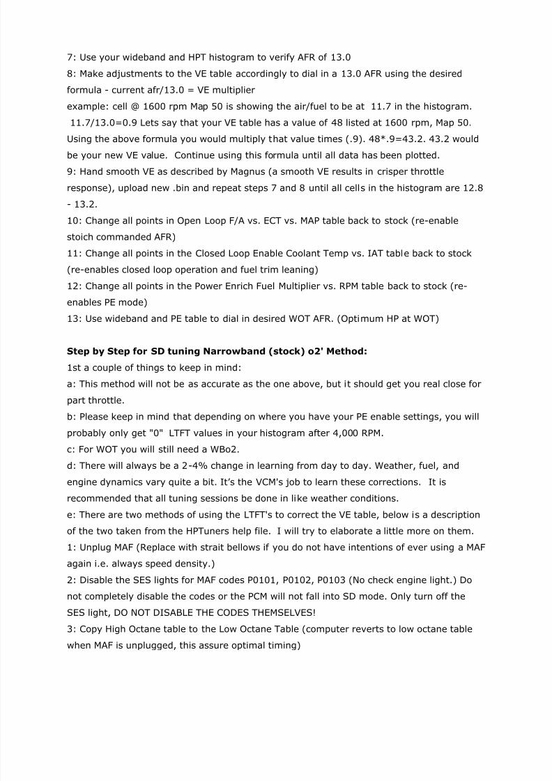
7: Use your wideband and HPT histogram to verify AFR of 13.0
8: Make adjustments to the VE table accordingly to dial in a 13.0 AFR using the desired
formula - current afr/13.0 = VE multiplier
example: cell @ 1600 rpm Map 50 is showing the air/fuel to be at 11.7 in the histogram.
11.7/13.0=0.9 Lets say that your VE table has a value of 48 listed at 1600 rpm, Map 50.
Using the above formula you would multiply that value times (.9). 48*.9=43.2. 43.2 would
be your new VE value. Continue using this formula until all data has been plotted.
9: Hand smooth VE as described by Magnus (a smooth VE results in crisper throttle
response), upload new .bin and repeat steps 7 and 8 until all cells in the histogram are 12.8
- 13.2.
10: Change all points in Open Loop F/A vs. ECT vs. MAP table back to stock (re-enable
stoich commanded AFR)
11: Change all points in the Closed Loop Enable Coolant Temp vs. IAT table back to stock
(re-enables closed loop operation and fuel trim leaning)12: Change all points in the Power Enrich Fuel Multiplier vs. RPM table back to stock (re-
enables PE mode)
13: Use wideband and PE table to dial in desired WOT AFR. (Optimum HP at WOT)
Step by Step for SD tuning Narrowband (stock) o2' Method:
1st a couple of things to keep in mind:
a: This method will not be as accurate as the one above, but it should get you real close for
part throttle.
b: Please keep in mind that depending on where you have your PE enable settings, you will
probably only get "0" LTFT values in your histogram after 4,000 RPM.
c: For WOT you will still need a WBo2.
d: There will always be a 2-4% change in learning from day to day. Weather, fuel, and
engine dynamics vary quite a bit. It’s the VCM's job to learn these corrections. It is
recommended that all tuning sessions be done in like weather conditions.
e: There are two methods of using the LTFT's to correct the VE table, below is a description
of the two taken from the HPTuners help file. I will try to elaborate a little more on them.
1: Unplug MAF (Replace with strait bellows if you do not have intentions of ever using a MAF
again i.e. always speed density.)
2: Disable the SES lights for MAF codes P0101, P0102, P0103 (No check engine light.) Do
not completely disable the codes or the PCM will not fall into SD mode. Only turn off the
SES light, DO NOT DISABLE THE CODES THEMSELVES!
3: Copy High Octane table to the Low Octane Table (computer reverts to low octane table
when MAF is unplugged, this assure optimal timing)
7/27/2019 LS1 Tuning Info
http://slidepdf.com/reader/full/ls1-tuning-info 20/25
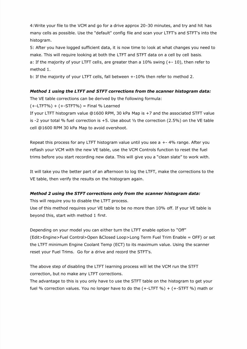
4:Write your file to the VCM and go for a drive approx 20-30 minutes, and try and hit has
many cells as possible. Use the "default" config file and scan your LTFT's and STFT's into the
histogram.
5: After you have logged sufficient data, it is now time to look at what changes you need to
make. This will require looking at both the LTFT and STFT data on a cell by cell basis.
a: If the majority of your LTFT cells, are greater than a 10% swing (+- 10), then refer to
method 1.
b: If the majority of your LTFT cells, fall between +-10% then refer to method 2.
Method 1 using the LTFT and STFT corrections from the scanner histogram data:
The VE table corrections can be derived by the following formula:
(+-LTFT%) + (+-STFT%) = Final % Learned
If your LTFT histogram value @1600 RPM, 30 kPa Map is +7 and the associated STFT value
is -2 your total % fuel correction is +5. Use about ½ the correction (2.5%) on the VE tablecell @1600 RPM 30 kPa Map to avoid overshoot.
Repeat this process for any LTFT histogram value until you see a +- 4% range. After you
reflash your VCM with the new VE table, use the VCM Controls function to reset the fuel
trims before you start recording new data. This will give you a “clean slate” to work with.
It will take you the better part of an afternoon to log the LTFT, make the corrections to the
VE table, then verify the results on the histogram again.
Method 2 using the STFT corrections only from the scanner histogram data:
This will require you to disable the LTFT process.
Use of this method requires your VE table to be no more than 10% off. If your VE table is
beyond this, start with method 1 first.
Depending on your model you can either turn the LTFT enable option to “Off”
(Edit>Engine>Fuel Control>Open &Closed Loop>Long Term Fuel Trim Enable = OFF) or set
the LTFT minimum Engine Coolant Temp (ECT) to its maximum value. Using the scanner
reset your Fuel Trims. Go for a drive and record the STFT's.
The above step of disabling the LTFT learning process will let the VCM run the STFT
correction, but no make any LTFT corrections.
The advantage to this is you only have to use the STFT table on the histogram to get your
fuel % correction values. You no longer have to do the (+-LTFT %) + (+-STFT %) math or
7/27/2019 LS1 Tuning Info
http://slidepdf.com/reader/full/ls1-tuning-info 21/25
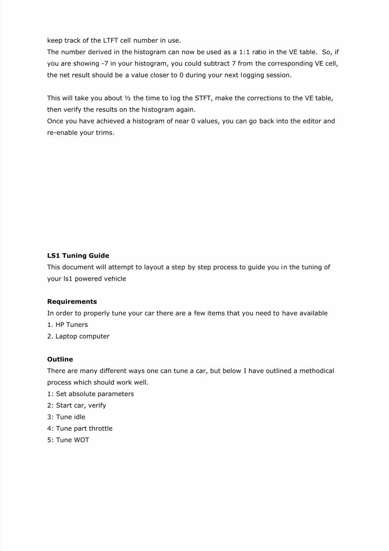
keep track of the LTFT cell number in use.
The number derived in the histogram can now be used as a 1:1 ratio in the VE table. So, if
you are showing -7 in your histogram, you could subtract 7 from the corresponding VE cell,
the net result should be a value closer to 0 during your next logging session.
This will take you about ½ the time to log the STFT, make the corrections to the VE table,
then verify the results on the histogram again.
Once you have achieved a histogram of near 0 values, you can go back into the editor and
re-enable your trims.
LS1 Tuning Guide
This document will attempt to layout a step by step process to guide you in the tuning of
your ls1 powered vehicle
Requirements
In order to properly tune your car there are a few items that you need to have available
1. HP Tuners
2. Laptop computer
Outline
There are many different ways one can tune a car, but below I have outlined a methodical
process which should work well.
1: Set absolute parameters
2: Start car, verify
3: Tune idle
4: Tune part throttle
5: Tune WOT
7/27/2019 LS1 Tuning Info
http://slidepdf.com/reader/full/ls1-tuning-info 22/25
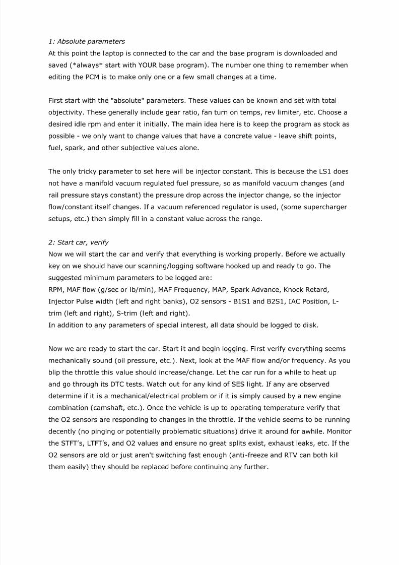
1: Absolute parameters
At this point the laptop is connected to the car and the base program is downloaded and
saved (*always* start with YOUR base program). The number one thing to remember when
editing the PCM is to make only one or a few small changes at a time.
First start with the "absolute" parameters. These values can be known and set with total
objectivity. These generally include gear ratio, fan turn on temps, rev limiter, etc. Choose a
desired idle rpm and enter it initially. The main idea here is to keep the program as stock as
possible - we only want to change values that have a concrete value - leave shift points,
fuel, spark, and other subjective values alone.
The only tricky parameter to set here will be injector constant. This is because the LS1 does
not have a manifold vacuum regulated fuel pressure, so as manifold vacuum changes (and
rail pressure stays constant) the pressure drop across the injector change, so the injectorflow/constant itself changes. If a vacuum referenced regulator is used, (some supercharger
setups, etc.) then simply fill in a constant value across the range.
2: Start car, verify
Now we will start the car and verify that everything is working properly. Before we actually
key on we should have our scanning/logging software hooked up and ready to go. The
suggested minimum parameters to be logged are:
RPM, MAF flow (g/sec or lb/min), MAF Frequency, MAP, Spark Advance, Knock Retard,
Injector Pulse width (left and right banks), O2 sensors - B1S1 and B2S1, IAC Position, L-
trim (left and right), S-trim (left and right).
In addition to any parameters of special interest, all data should be logged to disk.
Now we are ready to start the car. Start it and begin logging. First verify everything seems
mechanically sound (oil pressure, etc.). Next, look at the MAF flow and/or frequency. As you
blip the throttle this value should increase/change. Let the car run for a while to heat up
and go through its DTC tests. Watch out for any kind of SES light. If any are observed
determine if it is a mechanical/electrical problem or if it is simply caused by a new engine
combination (camshaft, etc.). Once the vehicle is up to operating temperature verify that
the O2 sensors are responding to changes in the throttle. If the vehicle seems to be running
decently (no pinging or potentially problematic situations) drive it around for awhile. Monitor
the STFT’ s, LTFT’s, and O2 values and ensure no great splits exist, exhaust leaks, etc. If the
O2 sensors are old or just aren't switching fast enough (anti-freeze and RTV can both kill
them easily) they should be replaced before continuing any further.
7/27/2019 LS1 Tuning Info
http://slidepdf.com/reader/full/ls1-tuning-info 23/25
3: Idle
Now that we have verified everything is in proper working order we can begin tuning. Idle is
the best place to start. Previously we set the desired idle rpm - subjectively decide if this
rpm correct. If not, change the value and re-evaluate. Once the desired idle rpm is
achieved, we can begin tweaking it for stability. Take note of the IAC counts. In a no load
situation (neutral, no ac) they should be no lower than 30, and no higher than 50. A hole
may need to be drilled in the throttle body or enlarge the one that is already there to bring
down the IAC values. Do this until they are acceptable. Now put a load on the car (D if
automatic, and put the AC on). The values here should be no higher than 120 or so. If they
are enlarge the hole.
Repeat the above process until the IAC values fall inline. If the idle is still unacceptable then
try adjusting the timing. Be careful of adding to much timing - it can give a great no loadidle, but with any kind of load will become erratic. A “hunting" idle is a sure sign of too
much timing. To adjust the timing at idle the base spark tables are the easiest place. The
tables are scaled vs. rpm and g/cyl of airflow. The rpm part is evident. To calculate the g/cyl
use the following formula:
g/cyl = 15 * MAF(g/sec) / RPM
This formula takes mass flow per unit time and converts it to mass flow per cylinder. The 15
is a constant which corresponds to the characteristics of a V8 running a 4-cycle combustion
cycle. The easiest thing to do is to load the log file into excel (export it as a CSV), then
create a formula in excel which applies the formula above.
4: Part Throttle
Not that the idle is correct and we have verified that the car is in proper working order we
can begin part throttle tuning. The first step in this is to record a long log file of driving, a
minimum of 20 minutes, but the longer the better.
Once we have a log file we can begin the data reduction. The first element we will tune will
be the fuel delivery. At part throttle the computer uses the MAF meter to find the amount of
air entering the engine. It then calculates the amount of fuel required to maintain a 14.7:1
A/F ratio. It injects this fuel by controlling the injector pulse width. The O2 sensors, which
are very accurate at 14.7:1, provide feedback to the computer and let it know how close it
is to the goal. The computer uses this feedback to tweak the fueling of the motor to achieve
a proper 14.7:1 a/f ratio. This "tweaking" is exhibited to through the STFT and LTFT

7/27/2019 LS1 Tuning Info
http://slidepdf.com/reader/full/ls1-tuning-info 24/25
parameters. These values indicate how the computer is correcting. Since injector flow and
pulse width are known with great precision, and we have no control over the internal
algorithms we will assume that any inaccuracy (which is exhibited by nonzero trim
percentages) is a result of an incorrect MAF transfer function.
In tuning part throttle we will tweak the MAF transfer function according to the LTFT values
we logged. There are 2 ways of doing this, the simplest is to view the LTFT values, average
them, and scale the entire MAF table by a percentage which will give the LTFT’s a 0 to -4.
LTFT’s are in units of percent so this is easy. If the average LTFT’ s are around +5 and we
want to shoot for -4, then we would just multiply the entire table by 109% (or an increase
of (+5 - (-4))=9 percent). Likewise if we were at -10 and wanted to shoot for negative 4 we
would decrease the entire table by 6 percent, or multiply by 94%.
Once this is complete repeat the logging process above and check the new LTFT value. Wewant to avoid positive LTFT values since they will be applied at WOT and will lead to
inconsistent fueling. Negative values are okay, though we shouldn't go too far out of whack.
The second option is a little more complicated. It uses the same premise above, but instead
of taking the average value it applies a localized LTFT correction to each point of the MAF
transfer function and derives a new curve. This method is not for everyone, but in certain
instances is very useful.
After repeating the above method until LTFT’ s fall in line, fueling should be complete. Now
we can address spark. Spark advance is a rather difficult item to tune directly, but here is a
suggested method. This method relies on a properly functioning knock sensor without any
desensitization.
Assuming the car is naturally aspirated and does not ping with the stock timing advance:
Take the entire timing table and increase it by 5 degrees. Now start driving the car while
logging. Try and emulate every possible driving condition. If pinging is detected at any point
back out. If the car pings constantly reduce timing across the board two degrees.
When done logging export the data to a CSV file and open in it excel. Here we will make a
pivot table. Create a column with g/cyl, spark retard, and rpm. Use these three items to
make a pivot table. Scale the table with g/cyl on the x axis and rpm on the y axis. Put spark
retard in the middle and set it's mode to average. You should group the axis along the same
lines as they are grouped in the PCM.
7/27/2019 LS1 Tuning Info
http://slidepdf.com/reader/full/ls1-tuning-info 25/25
We now have a table of the average spark retard taken out at each timing point. Now go to
the table in the PCM and subtract 75% of this value from the actual spark advance at each
point where spark retard occurred. Re-log the car. Repeat the procedure until no spark
retard is detected. The timing curve should now be tuned.
If the car is an automatic we will now start tuning shift pressure, shift points, and TCC.
5: WOT tuning
The first thing to do is make a quick WOT pass in a low gear (a low load) and check both
O2's and knock retard. O2's are NOT accurate or precise at this a/f ratio, but can still be
used for a ballpark estimate. If they aren't 850-950 we will adjust the PE vs. RPM table
accordingly. This table is where all fueling changes at WOT are made. If knock retard is
present we need to localize it to a point in the timing table, so using the method above forpart throttle tuning, we will do the same thing for WOT tuning.
If either spark or fuel is changed then go back and check the other by logging. A wideband
O2 sensor is required to accurately set the fuel map. If wideband feedback is available the
a/f ratio will generally end the richest at your torque peak and leaning out from there to
peak horsepower and then a little rich before and after the shift point for safety.
Once fuel and spark are set then begin playing with the shift points and transmission
parameters automatic cars. If it’s a manual transmission we are good to go!
Follow-Up
After a week or so you need to re-verify all your logged values and ensure they haven't
drifted. If they have, repeat the processes necessary to bring them back in line.