Ceramic Injection Molding - InTech - Open Science Open Minds

Low-Pressure Injection Molding of Ceramic Springs
Israel Krindges and Raquel Andreola
Universidade de Caxias do Sul, 95070-560 Caxias do Sul, RS, Brazil
Claudio A. Perottoni and Janete E. Zorzi*
Universidade de Caxias do Sul, 95070-560 Caxias do Sul, RS, BrazilInstituto de Fısica, Universidade Federal do Rio Grande do Sul, 91501-970 Porto Alegre, RS, Brazil
Injection molding has important advantages over other methods for the production of advanced ceramic parts withcomplex shapes. In this work, low-pressure injection molding was used to produce helical ceramic springs using two differentkinds of molds. The ceramic powders used were submicrometer-sized alumina and partially stabilized zirconia. Sinteredalumina and zirconia springs were obtained free of defects, with densities from 96% to 99% of the theoretical value. Inpreliminary mechanical tests, these ceramic springs supported axial deformations up to 10% before failure.
Introduction
There has been a growing interest in recent years inthe fabrication of ceramic springs targeted for applica-tions that demand resistance to oxidative damage or cor-rosion in harsh environments at room as well as at hightemperatures.1–5 Ceramic springs and windings havebeen prepared by machining cylindrical compacts or byextrusion of sol-derived pastes or ceramic–polymeric mix-tures.1–6 While the first process is flexible, but expensive,the latter suffers from difficulties in extracting polymer-based binders while keeping the spring’s shape unaltered.
Low-pressure injection molding (LPIM) of ceramicparts has been shown to be well suited for complexceramic parts production and has many advantages
compared with high-pressure injection molding.7,8 Infact, LPIM involves a significantly lower manufacturingcost for dies and less die wears (due to lower moldingpressures and temperatures) and less expensive injectionequipment. These advantages make this forming meth-od interesting for near-net-shape forming of complexparts in the range of 100–10,000 units.7,8 However,lower injection pressures are only made possible by theuse of a relatively large proportion of low-viscosity bind-ers in the injection mixture. Hence, LPIM usage hasbeen limited mainly by the difficulties associated withthe process of binder removal. The difficulties encoun-tered during binder removal are even greater when theparts have large cross-section and are prepared withsubmicrometer-sized ceramic powder.7,8
The ceramic powder plus binder mixture used forLPIM should be optimized for high fluidity while keep-ing the ceramic content as high as possible. For the suc-cessful production of ceramic parts by LPIM, it is thus
Int. J. Appl. Ceram. Technol., 5 [3] 243–248 (2008)DOI:10.1111/j.1744-7402.2008.02226.x
Ceramic Product Development and Commercialization
This work was partially supported by CNPq and FAPERGS (Brazil).
r 2008 The American Ceramic Society

necessary to develop a suitable binder formulation. Thisis a difficult task, especially for fine particles, as it involvesa large number of variables related to physical and chemicalproperties of binder components, and the interactionbetween them and with the powder surface.7,8
In this work, we present a procedure for theproduction of ceramic springs by LPIM. Two methodsof molding were tested. Ceramic parts were first producedby injection into a helical copper coil. Green ceramicparts were recovered after the removal of copper walls.The second strategy for molding of ceramic springsmade use of a brass mold. In both cases our intentionwas to develop a simple and low-cost method to moldhelical springs with good reproducibility. The methodsproposed here are well suited for the productionof high-temperature advanced ceramic springs, heatingelements, and ceramic electrical and mechanical devices.The quality of the sintered ceramic parts was assessed bydensity and Vickers hardness measurements. Stress–strain curves for the ceramic springs were obtainedfrom compression tests.
Experimental Procedure
Raw Materials and Powder/Binder Mixtures
Commercially available Al2O3 (alumina) powderused in this work was submicrometer-sized aluminaA-1000SG (Alcoa, Leetsdale, PA), which was used as-received. According to the supplier’s data, the powder’ssurface area is 9 m2/g, with 99.8% purity (0.04% MgO,0.03% SiO2, 0.02% Fe2O3, 0.07% Na2O, and 0.02%CaO) and an average particle size of 0.4 mm.
The commercially available zirconia (ZrO2) usedwas TZ-3YS (Tosoh, Tokyo, Japan). According to thesupplier’s data, the composition is 94.8% zirconia,5.16% Y2O3 (3 mol%), 0.005% alumina, 0.005%SiO2, 0.004% Fe2O3, and 0.003% Na2O. The densi-ty is 6.05 g/cm3, the powder’s surface area is 772 m2/g,and the average particle size is 0.59 mm.
The mixture for injection molding of alumina partswas made in an LPIM machine (Peltsman MIGL-33,Minneapolis, MN). The mixture of alumina and bind-ers for injection was prepared directly in the LPIM ma-chine, with 86 wt% of alumina and 14 wt% of wax-based binder (55 vol%). Binder composition was thesame as that used in previous works.7,8 To guaranteegood homogeneity, the mixture was mixed for 20 h at901C before injection.
For the production of zirconia springs, a home-made injection machine was built (maximum load of300 g) and used to mix and inject the powder/bindermixture. In the zirconia/binder mixture, the bindercontent was increased to 15 wt% to improve powderdispersion in the mixture.
Copper Coil
To obtain ceramic springs with a minimum man-ufacturing cost, a copper tube was first used as a mold(Fig. 1A). The copper helical coil was rolled manually,making this procedure cheap and simple to be imple-mented. The process, however, has the inconvenience
Fig. 1. (A) Copper coil and (B) brass mold coated with a greenpolytetrafluoroethylene film used for the low-pressure injectionmolding of ceramic springs.
244 International Journal of Applied Ceramic Technology—Krindges, et al. Vol. 5, No. 3, 2008
that the green ceramic parts are recovered only after thechemical or electrochemical removal of the copper walls.
The alumina-based mixture was injected into thecopper helical coils using a metallic syringe. The aluminapowder/binder mixture prepared in the Peltsman LPIMmachine was hot pressed in a piston-cylinder device toform cylinders with 22 mm diameter and 40 mm height.These cylinders were thus fed in the metallic syringe usedto inject the mixture into the copper coil. Both the syringeand the copper coil mold were heated to B1201C beforeinjection. Removal of the copper wall was accomplishedby immersion of the copper coils into a nitric acid solution(50 vol%) or by electrolysis (I 5 140–240 mA, V 5 15–25 V) in a CuSO4 solution. It takes a few hours to com-pletely remove the copper wall. During the entire processof copper removal it is necessary to keep the temperaturebelow 301C to avoid any flow of the injected mixture.
Brass Mold
The second strategy for molding of ceramic springsmade use of a brass mold lined with a fine polytetra-fluoroethylene (PTFE) film (Fig. 1B). This antiadherentfilm makes mold lubrication unnecessary. The brass moldwas made multipart to simplify the mechanical extractionof the green ceramic spring after injection.
The alumina mixture was injected into the brassmold at 901C and 400 kPa of pressure, keeping thepressure applied for 12 s, using the MIGL-33 LPIMmachine. Pressure, temperature, and duration of theinjection process were varied in order to obtain greenceramic parts free of defects. Higher injection tempera-tures promote the formation of small internal bubbles,whereas higher pressures lead to superficial defects.
After we have successfully produced aluminasprings free of defects, the same brass mold was usedto make zirconia springs. However, given the high costof zirconia powder, the ceramic/binder mixture andinjection were made with the aid of a little homemadeinjection machine. In this process, temperature andpressure could not be controlled as accurately as withthe Peltsman LPIM machine. After thorough mixing,the zirconia powder/binder mixture, heated to 901C,was mechanically pressed by a piston and injected intothe brass mold previously heated in an oven.
Debinding, Sintering, and Mechanical Tests
The green ceramic parts were subjected to debindingimmersed into alumina powder (A-1000SG), up to a
temperature of 2501C (wicking).7,8 After this step, theparts were fired in air to 10001C, and finally sintered at16001C/2 h (alumina) and 15001C/2 h (zirconia).
The density of the sintered ceramic parts was mea-sured by the Archimedes method. Vickers hardness wasmeasured for loads of 500 and 1000 g. Compression testswere performed in a mechanical testing machine (EMICDL3000, Parana, Brazil) in order to evaluate the spring’sconstant and maximum load and deformation beforefailure. Only ceramic springs produced with the brassmold were used for the compression tests.
Results and Discussion
Molding and Sintering
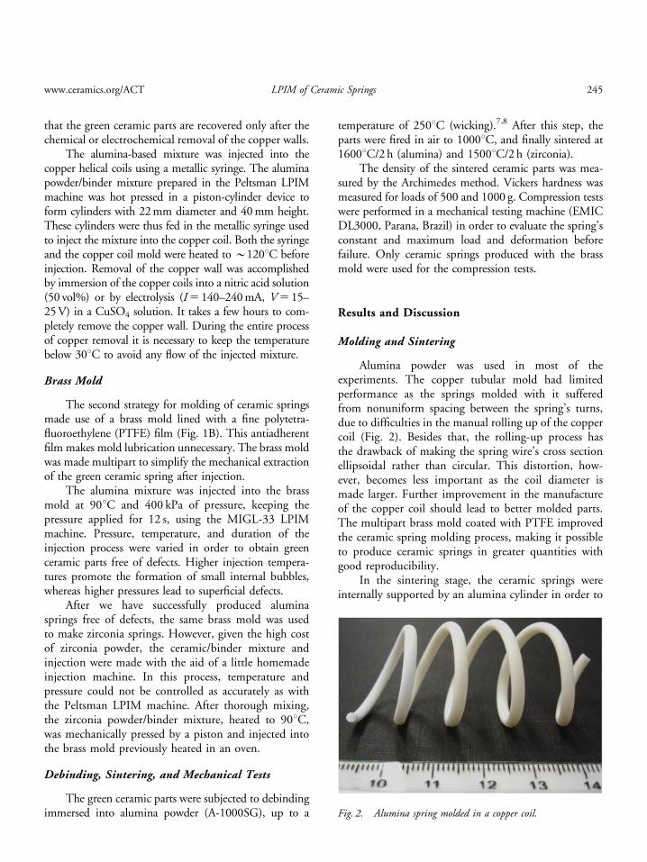
Alumina powder was used in most of theexperiments. The copper tubular mold had limitedperformance as the springs molded with it sufferedfrom nonuniform spacing between the spring’s turns,due to difficulties in the manual rolling up of the coppercoil (Fig. 2). Besides that, the rolling-up process hasthe drawback of making the spring wire’s cross sectionellipsoidal rather than circular. This distortion, how-ever, becomes less important as the coil diameter ismade larger. Further improvement in the manufactureof the copper coil should lead to better molded parts.The multipart brass mold coated with PTFE improvedthe ceramic spring molding process, making it possibleto produce ceramic springs in greater quantities withgood reproducibility.
In the sintering stage, the ceramic springs wereinternally supported by an alumina cylinder in order to
Fig. 2. Alumina spring molded in a copper coil.
www.ceramics.org/ACT LPIM of Ceramic Springs 245
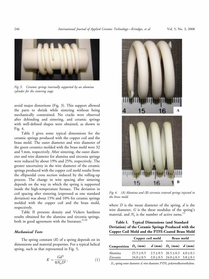
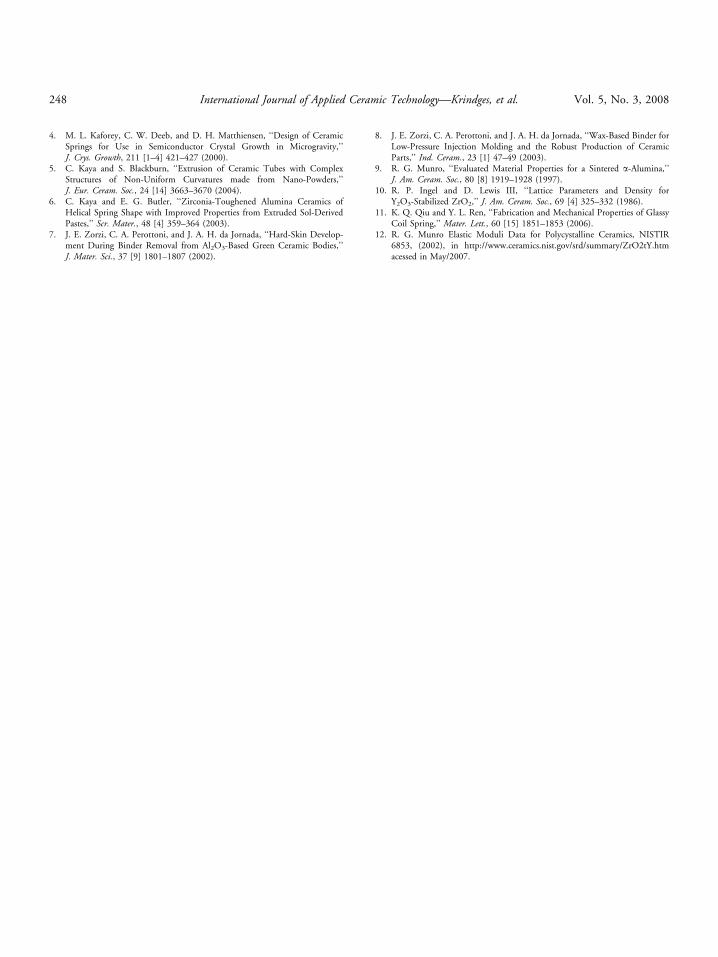
avoid major distortions (Fig. 3). This support allowedthe parts to shrink while sintering without beingmechanically constrained. No cracks were observedafter debinding and sintering, and ceramic springswith well-defined shapes were obtained, as shown inFig. 4.
Table I gives some typical dimensions for theceramic springs produced with the copper coil and thebrass mold. The outer diameter and wire diameter ofthe green ceramics molded with the brass mold were 32and 5 mm, respectively. After sintering, the outer diam-eter and wire diameter for alumina and zirconia springswere reduced by about 19% and 25%, respectively. Thegreater uncertainty in the wire diameter of the ceramicsprings produced with the copper coil mold results fromthe ellipsoidal cross section induced by the rolling-upprocess. The change in wire spacing after sinteringdepends on the way in which the spring is supportedinside the high-temperature furnace. The deviation incoil spacing after sintering (expressed as one standarddeviation) was about 15% and 10% for ceramic springsmolded with the copper coil and the brass mold,respectively.
Table II presents density and Vickers hardnessresults obtained for the alumina and zirconia springs,both in good agreement with the literature.9,10
Mechanical Tests
The spring constant (K) of a spring depends on itsdimensions and material properties. For a typical helicalspring, such as that represented in Fig. 5,
K ¼ Gd 4
8NaD3; ð1Þ
where D is the mean diameter of the spring, d is thewire diameter, G is the shear modulus of the spring’smaterial, and Na is the number of active turns.11
Fig. 3. Ceramic springs internally supported by an aluminacylinder for the sintering stage.
Fig. 4. (A) Alumina and (B) zirconia sintered springs injected inthe brass mold.
Table I. Typical Dimensions (and StandardDeviation) of the Ceramic Springs Produced with theCopper Coil Mold and the PTFE-Coated Brass Mold
Composition
Copper coil mold Brass mold
Do (mm)� d (mm) Do (mm) d (mm)
Alumina 25.570.5 2.570.5 26.570.3 4.070.1Zirconia 24.070.5 2.070.5 24.070.3 3.870.1
�Do, spring outer diameter; d, wire diameter; PTFE, polytetrafluoroethylene.
246 International Journal of Applied Ceramic Technology—Krindges, et al. Vol. 5, No. 3, 2008

Figure 6 shows some results obtained from com-pression tests carried out with ceramic parts producedwith the brass mold. In compression tests performedwith alumina springs, the maximum applied load beforefailure was 9077 N, and the relative deflection(erel 5Dl/l0) was 9.471.0%. The quoted uncertaintyrefers to the mean’s standard deviation for a set of20 measurements. In addition, 10 zirconia springswere tested and failure occurred for an applied loadof 96710 N and erel 5 1272%. Both alumina andzirconia springs follow Hooke’s law, with spring con-stants around 250 and 160 N/mm, respectively, whichconforms to the lower shear modulus of zirconiain comparison to alumina.12
Conclusions
Alumina and zirconia helical springs were producedby LPIM. After sintering, parts molded with sub-micrometer-sized powders were obtained with highdensity and good mechanical properties. Mechanicalfailure of alumina and zirconia springs occurred underloads around 90 N and relative deflections about 10%.Ceramic parts with good reproducibility were obtained,particularly with the PTFE-coated brass mold. Further-more, provided that the binder composition and theceramic volume loading in the injection mixture arecorrectly chosen, the method should be applicableto ceramic and metal powders in general. Uniformityin sample preparation and testing conditions allowed abetter comparison of the effect of the ceramic materialon the spring’s properties. The effect of the microstruc-ture on the spring’s properties as well as the possibleelectronic, mechanical, thermal, and tribological appli-cations of the helical ceramic springs should be furtherinvestigated.
References
1. J. K. Wright, R. M. Thomson, and J. R. G. Evans, ‘‘On the Fabrication ofCeramics Windings,’’ J. Mater. Sci., 25 [1] 149–156 (1990).
2. W. Nakao, S. Mori, J. Nakamura, K. Takahashi, and K. Ando, ‘‘Self-Crack-Healing Behaviour of Mullite/SiC Particle/SiC Whisker Multi-Composites andPotential Use for Ceramic Springs,’’ J. Am. Ceram. Soc., 89 [4] 1352–1357(2006).
3. T. Hamilton, M. Gopal, E. Atchley, and J. E. Smith Jr., ‘‘ExperimentalInvestigation on the Mechanical Performance of Helical Ceramic Spring,’’J. Mater. Sci., 38 [15] 3331–3335 (2003).
Table II. Density and Vickers Hardness of Aluminaand Zirconia Ceramic Springs
Composition
Greendensity(g/cm3)
Sintereddensity(g/cm3)
Vickershardness
500 gload
(kgf/mm2)
Vickershardness1000 gload
(kgf/mm2)
Alumina 2.6670.01 3.8770.01 1659721 1627715Zirconia 3.3870.01 6.0170.01 139778 138777
Fig. 5. Schematics of spring design.
Fig. 6. Compressive load versus displacement for two ceramichelical springs.
www.ceramics.org/ACT LPIM of Ceramic Springs 247
4. M. L. Kaforey, C. W. Deeb, and D. H. Matthiensen, ‘‘Design of CeramicSprings for Use in Semiconductor Crystal Growth in Microgravity,’’J. Crys. Growth, 211 [1–4] 421–427 (2000).
5. C. Kaya and S. Blackburn, ‘‘Extrusion of Ceramic Tubes with ComplexStructures of Non-Uniform Curvatures made from Nano-Powders,’’J. Eur. Ceram. Soc., 24 [14] 3663–3670 (2004).
6. C. Kaya and E. G. Butler, ‘‘Zirconia-Toughened Alumina Ceramics ofHelical Spring Shape with Improved Properties from Extruded Sol-DerivedPastes,’’ Scr. Mater., 48 [4] 359–364 (2003).
7. J. E. Zorzi, C. A. Perottoni, and J. A. H. da Jornada, ‘‘Hard-Skin Develop-ment During Binder Removal from Al2O3-Based Green Ceramic Bodies,’’J. Mater. Sci., 37 [9] 1801–1807 (2002).
8. J. E. Zorzi, C. A. Perottoni, and J. A. H. da Jornada, ‘‘Wax-Based Binder forLow-Pressure Injection Molding and the Robust Production of CeramicParts,’’ Ind. Ceram., 23 [1] 47–49 (2003).
9. R. G. Munro, ‘‘Evaluated Material Properties for a Sintered a-Alumina,’’J. Am. Ceram. Soc., 80 [8] 1919–1928 (1997).
10. R. P. Ingel and D. Lewis III, ‘‘Lattice Parameters and Density forY2O3-Stabilized ZrO2,’’ J. Am. Ceram. Soc., 69 [4] 325–332 (1986).
11. K. Q. Qiu and Y. L. Ren, ‘‘Fabrication and Mechanical Properties of GlassyCoil Spring,’’ Mater. Lett., 60 [15] 1851–1853 (2006).
12. R. G. Munro Elastic Moduli Data for Polycystalline Ceramics, NISTIR6853, (2002), in http://www.ceramics.nist.gov/srd/summary/ZrO2tY.htmacessed in May/2007.
248 International Journal of Applied Ceramic Technology—Krindges, et al. Vol. 5, No. 3, 2008