Long-Range UHF Radars for Ground Control of Airborne ...
12
VOLUME 12, NUMBER 2, 2000 LINCOLN LABORATORY JOURNAL 205 Long-Range UHF Radars for Ground Control of Airborne Interceptors William W. Ward and F. Robert Naka ■ The standard Air Force radars available in the early 1950s had major shortcomings for air-battle management in the face of plausible threats. At that time Lincoln Laboratory was achieving impressive success in developing UHF radars for airborne early warning with moving-target indication by changing from shorter to longer operating wavelengths. It appeared that similar innovations would also yield major performance improvements for radars devoted to the ground control of airborne interceptors. Lincoln Laboratory developed and fielded two different UHF radars that showed that this promise could be fulfilled. Both had quite large antennas rotating in azimuth. A narrowband radar operating near 425 MHz was built on Jug Handle Hill near West Bath, Maine; it became a primary sensor for the Cape Cod System and the Experimental SAGE Subsector. A broadband radar operating across the 400-to- 450-MHz band was built atop Boston Hill near North Andover, Massachusetts. This radar was designed as a test bed for the development of techniques to combat active electronic jamming and passive countermeasures such as chaff dispensed by hostile aircraft. These radars paved the way for subsequent Air Force efforts to achieve frequency diversity in its air-defense network. S - - radars provided the primary input data for ground control of intercepts (GCI) in the Cape Cod System, which was Lincoln Laboratory’s early dem- onstration of air-battle management by a central computer. By 1954, it became apparent that these sensors, only marginally more capable than radars de- veloped by the end of World War II, displayed an un- acceptable amount of clutter on their plan position indicators (PPIs). The circuits intended to cancel out echoes from fixed and slowly moving targets and to display only those from high-speed targets such as air- planes in flight were not fully effective. The uncanceled echoes from mountains, buildings, pre- cipitation, and occasional flocks of birds produced numerous false targets that had to be identified and eliminated (mapped out) before the airborne targets of interest could be tracked from their digitized coor- dinates. The proportion of the radars’ coverage that had to be sacrificed in this way was unacceptably large. Could anything be done about these problems? Deficiencies also existed in the vertical coverage provided by these radars. They had been designed to detect aircraft powered by piston engines. Such air- craft do not routinely operate much above 20,000 ft. The advent of heavy bombers and interceptors pow- ered by jet engines meant that an airborne threat would soon be able to escape radar detection by flying over the radars’ coverage volumes. As a result of the 1952 Summer Study at MIT in Cambridge, Massachusetts, Lincoln Laboratory be- gan developing and testing UHF airborne-early-
Transcript of Long-Range UHF Radars for Ground Control of Airborne ...

• WARD AND NAKALong-Range UHF Radars for Ground Control of Airborne Interceptors
VOLUME 12, NUMBER 2, 2000 LINCOLN LABORATORY JOURNAL 205
Long-Range UHF Radars forGround Control of AirborneInterceptorsWilliam W. Ward and F. Robert Naka
■ The standard Air Force radars available in the early 1950s had majorshortcomings for air-battle management in the face of plausible threats. At thattime Lincoln Laboratory was achieving impressive success in developing UHFradars for airborne early warning with moving-target indication by changingfrom shorter to longer operating wavelengths. It appeared that similarinnovations would also yield major performance improvements for radarsdevoted to the ground control of airborne interceptors. Lincoln Laboratorydeveloped and fielded two different UHF radars that showed that this promisecould be fulfilled. Both had quite large antennas rotating in azimuth. Anarrowband radar operating near 425 MHz was built on Jug Handle Hill nearWest Bath, Maine; it became a primary sensor for the Cape Cod System and theExperimental SAGE Subsector. A broadband radar operating across the 400-to-450-MHz band was built atop Boston Hill near North Andover, Massachusetts.This radar was designed as a test bed for the development of techniques tocombat active electronic jamming and passive countermeasures such as chaffdispensed by hostile aircraft. These radars paved the way for subsequent AirForce efforts to achieve frequency diversity in its air-defense network.
S - - radarsprovided the primary input data for groundcontrol of intercepts (GCI) in the Cape Cod
System, which was Lincoln Laboratory’s early dem-onstration of air-battle management by a centralcomputer. By 1954, it became apparent that thesesensors, only marginally more capable than radars de-veloped by the end of World War II, displayed an un-acceptable amount of clutter on their plan positionindicators (PPIs). The circuits intended to cancel outechoes from fixed and slowly moving targets and todisplay only those from high-speed targets such as air-planes in flight were not fully effective. Theuncanceled echoes from mountains, buildings, pre-cipitation, and occasional flocks of birds producednumerous false targets that had to be identified and
eliminated (mapped out) before the airborne targetsof interest could be tracked from their digitized coor-dinates. The proportion of the radars’ coverage thathad to be sacrificed in this way was unacceptablylarge. Could anything be done about these problems?
Deficiencies also existed in the vertical coverageprovided by these radars. They had been designed todetect aircraft powered by piston engines. Such air-craft do not routinely operate much above 20,000 ft.The advent of heavy bombers and interceptors pow-ered by jet engines meant that an airborne threatwould soon be able to escape radar detection by flyingover the radars’ coverage volumes.
As a result of the 1952 Summer Study at MIT inCambridge, Massachusetts, Lincoln Laboratory be-gan developing and testing UHF airborne-early-

• WARD AND NAKALong-Range UHF Radars for Ground Control of Airborne Interceptors
206 LINCOLN LABORATORY JOURNAL VOLUME 12, NUMBER 2, 2000
warning (AEW) radar systems with airborne-moving-target-indication (AMTI) capability [1]. These radarsdemonstrated in flight tests some of the advantages ofoperating at lower frequencies (longer wavelengths),which are discussed in the article entitled “Displaced-Phase-Center Antenna Technique,” by Charles Ed-ward Muehe and Melvin Labitt, in this issue. For ex-ample, echoes from precipitation and birds werereduced because the scatterers were smaller in termsof wavelength. The success of the AEW program ledradar designers to believe that operating GCI radarsat longer wavelengths could solve many of the prob-lems that radars experienced at higher-frequency L-and S-bands. Of course, the horizontal aperture ofthe rotating radar antenna needed to be wider in pro-portion to the wavelength ratio to maintain the sameresolution in azimuth. Keeping the vertical dimen-sion of the antenna about the same meant that thevertical beamwidth was broader so that the coveragein elevation angle extended to correspondingly—andgratifyingly—higher altitudes. The resolution inrange could be preserved by using transmitted pulsesof the same length as before.
Other benefits were associated with the move tolonger wavelengths. Engineers realized by this timethat—all other things being equal—the effectivenessof a pulsed radar in searching for targets at unknownpositions throughout a given volume is proportionalto the product of the average power of its transmitterand the aperture area of its receiving antenna, inde-pendent of the wavelength at which the radar oper-ates. Thus using longer wavelengths would increasethe effectiveness of a pulsed radar by increasing thehorizontal aperture of the rotating antenna. Transmit-ters with higher peak and average powers at longerwavelengths would be easier to build than those atshorter wavelengths because the physical dimensionsof the radio-frequency (RF) components would belarger. Increasing the size of the RF componentswould reduce the likelihood of breakdown withinthem because of high electromagnetic-field strengths.
Longer wavelengths also facilitated efforts to resistjamming, an unanticipated vulnerability of radar op-erations. In the early years of World War II, radar de-velopers such as those at the “RadLab,” MIT’s Radia-tion Laboratory [2, 3], were elated just to get their
equipment to work properly in the field. They hadenough problems to solve without also consideringthat an enemy might try to jam the radars’ operationwith electronic countermeasures. Just as the radar de-velopers did not initially anticipate jamming tech-niques, the Axis forces, especially submarine crews,were initially unaware that they were vulnerable todetection by airborne radars. Soon enough, on allsides researchers began to invent measures to counteror reduce the effectiveness of their opponents’ radars.
For example, the Radio Research Laboratory [3] atHarvard University worked hard to develop activeelectronic jamming and passive countermeasures(dropping chaff ) to interfere with radars like the onesunder development about a mile down the street atthe MIT Radiation Laboratory. It therefore becamenecessary for the radar developers to devise counter-countermeasures (CCMs) for their equipment.
With substantial electronic jamming of radiotransmissions from the western world already in ef-fect, there was no doubt that the Soviet Union wouldemploy radar countermeasures. The standard AirForce GCI radars that were available in the early1950s offered little in the way of CCM capability. Anew generation of GCI radars needed the flexibilityto accommodate emerging CCM techniques to oper-ate in assorted frequency bands. They also requiredthe ability to burn through wideband noise jammingand provide coverage on airborne targets of interestout to a useful extended range. The sidebar entitled“The Air Force Frequency-Diversity Radar Program”describes how these requirements were incorporatedin new radars. An incoming bomber force facing anarray of frequency-diverse air-defense radars neededto carry an equally diverse collection of active andpassive countermeasures, adding to the complexity ofthe aircraft and reducing their combined useful pay-load of bombs.
Lincoln Laboratory’s contributions to this effortwere made at a practical level. Two different largeUHF GCI radars were developed and put into opera-tion at field sites in New England.
Jug Handle Hill, West Bath, Maine
In 1954 Lincoln Laboratory undertook to cobble to-gether a demonstration UHF GCI radar in a hurry.

• WARD AND NAKALong-Range UHF Radars for Ground Control of Airborne Interceptors
VOLUME 12, NUMBER 2, 2000 LINCOLN LABORATORY JOURNAL 207
Its characteristics were spelled out by midyear. Theantenna, 120 ft wide by 16 ft high, was not expectedto be a great construction challenge. Its mechanicaltolerances in terms of wavelength were no more strin-gent than those of the ≈1300-MHz AN/FPS-3, thena standard Air Force heavy radar for fixed GCI instal-
lations, which had a 40-ft-wide by 16-ft-high antennareflector. Both yielded approximately 1.5°-wide radarbeams and blips on their PPI displays. Rotating theUHF GCI radar antenna at 6 rpm would make itsdata-output characteristics essentially the same asthose of the AN/FPS-3. The new radar promised to
Rome Air Develop-ment Center, Griffiss Air ForceBase, New York, let design-studycontracts for six new ground con-trol of intercepts (GCI) radars,each to operate in a segment of thefrequency range 214 to 5900MHz. At that time, Air Force GCIradars were moving through attri-tion toward occupancy of onlytwo frequency bands: the AN/FPS-7 surveillance and height-finding radar with stacked beamsoperated at 1300 MHz, and theAN/FPS-6 height-finding radaroperated at 2900 MHz. These tworadars, lineal descendants of ra-dars developed during World WarII, constituted what amounted toa single-frequency air-defense ra-dar system. The frequency-diver-sity (FD) radar program was to re-verse that trend.
The spread of operating fre-quencies to be provided by the FDradar program promised to makeit more costly in terms of payloadfor an airborne intruder to pen-etrate and survive in the defensiveradar environment, as discussedin the main text. At the same time,the new program would enhance
the Air Force’s GCI capabilities, inparticular its ability to feed high-quality data to the Semi-Auto-matic Ground Environment(SAGE) air-defense system. Table1, on the following page, showsthe characteristics of the Air Forcefrequency-diversity radars.
Five of the six proposed radarswere selected for prototype devel-opment, and four were producedin quantity. These five systems intheir prototype forms were in-stalled for testing and evaluationat operational Air Force sites inAlabama, Louisiana, and Missis-sippi, part of the Mobile, Ala-bama, Air-Defense Sector. Theirtest programs began in 1959.
In addition, the AN/GLA-8signal processing system, built byAirborne Instrument Laboratory,was an important common ad-junct to each frequency-diversityradar. This equipment included aspecial antijamming console usedby the radar’s human counter-countermeasures (CCMs) opera-tor. As discussed in the main text,CCMs such as frequency hoppingand PRF jitter/stagger are usefulin reducing the effectiveness of
both passive countermeasures(chaff, for example) and activecountermeasures (spot and noisejamming, and signal repeaters).The wise use of the many featuresof a highly flexible FD radar re-quired special skills and sophisti-cated technological support.
The Jug Handle Hill radar be-gan operation in October 1955.Without question, the measure ofsuccess it achieved despite thebearing problems of its gargan-tuan rotating antenna paved theway for the three lower-frequencyFD radars.
The Boston Hill radar, whichbegan operation in 1959, was con-temporary with the AN/FPS-35but had quite a different design.They should not be confused.Four AN/FPS-35s were procuredby Rome Air Development Cen-ter under a prototype contract forearly installation at field sites andoperation by Air Force crews. Bos-ton Hill, on the other hand, wasintended to serve as LincolnLaboratory’s long-term test bedfor development and evaluationof CCM techniques, hence its for-mal name, CCM Radar Mark I.
T H E A I R F O R C E F R E Q U E N C Y - D I V E R S I T YR A D A R P R O G R A M

• WARD AND NAKALong-Range UHF Radars for Ground Control of Airborne Interceptors
208 LINCOLN LABORATORY JOURNAL VOLUME 12, NUMBER 2, 2000
be a prime input sensor for the Cape Cod System andlater for the Experimental Semi-Automatic GroundEnvironment (SAGE) Subsector.
The design of the electronics for the new radar wastaken directly from that of the AN/APS-70, LincolnLaboratory’s UHF AEW radar with AMTI, whichwas then undergoing development and testing (seethe article entitled “Displaced-Phase-Center AntennaTechnique,” by Charles Edward Muehe and MelvinLabitt, in this issue). The moving-target-indicator(MTI) circuitry of the UHF GCI radar was simpler.
Adopting the magnetron-based transmitter designof the AN/APS-70 was a compromise decision. Al-though the transmitter and its associated circuitrycould be readily copied from the AEW-radar equip-ment, the transmitter was not very powerful. Anymagnetron has a random start-up phase on eachpulse, making the radar’s signal processing equipmentmore complicated. We would have preferred to builda fully coherent radar of the master-oscillator/power-amplifier family (see the article “Early Advances inRadar Technology for Aircraft Detection,” by DonaldL. Clark, in this issue). That approach would have re-quired using a high-power amplifier such as a triode,tetrode, klystron, or amplitron, but no suitable tubewas immediately available. Furthermore, the 2% in-stantaneous RF bandwidth of the magnetron couldnot accommodate the rapid changes of transmittedfrequency—perhaps even pulse to pulse—requiredfor some radar CCM techniques.
Work on this UHF GCI radar, ultimately desig-
nated the AN/FPS-31 (XD-1), got under way in thefall of 1954. Figure 1 shows the transmitter and QK-508 magnetron for the AN/FPS-31 (XD-1) radar. Asite near the Maine coast on Jug Handle Hill, WestBath, was selected to serve as a counterpart to theshoreline GCI radars at South Truro on Cape Cod,Massachusetts, and Montauk Point on Long Island,New York, that were already integrated into the CapeCod System. The radar began operation in October
FIGURE 1. Transmitter of the AN/FPS-31 (XD-1) UHFground control of intercepts (GCI) radar. The QK-508 mag-netron (middle) fits into a pulse transformer and is poweredby the modulator cabinet on the right. The high-power RFoutput pulses travel from the magnetron through a sectionof 3-1/8-in flexible coaxial transmission line (at the left) tothe vertical waveguide run (see also Figures 2 and 3). Notethe windlass (essential when changing magnetrons) and thearrangements for liquid cooling of the magnetron.
Table 1. Characteristics of the Air Force Frequency-Diversity Radars
Function Frequency Range (MHz) Equipment Designator Contractor
Surveillance 214–236 AN/FPS-24 GE
Surveillance 400–450 AN/FPS-35 Sperry
Surveillance 510–690 AN/FPS-28* Raytheon
Surveillance and 2320–2680 AN/FPS-27 Westinghouseheight finding (stacked beams)
Height finding (nodding beam) 5400–5900 AN/FPS-26 AVCO Manufacturing Co.,Crosley Division
*Not produced in quantity
Windlass
Flexible coaxialtransmission line
• WARD AND NAKALong-Range UHF Radars for Ground Control of Airborne Interceptors
VOLUME 12, NUMBER 2, 2000 LINCOLN LABORATORY JOURNAL 209
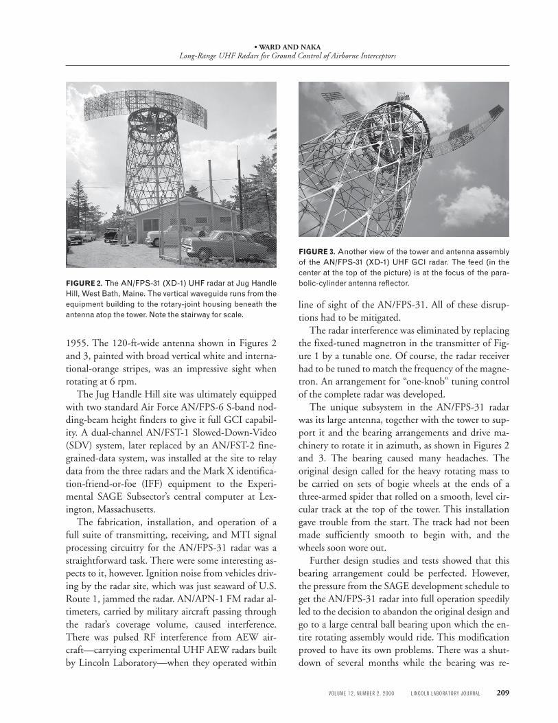
FIGURE 2. The AN/FPS-31 (XD-1) UHF radar at Jug HandleHill, West Bath, Maine. The vertical waveguide runs from theequipment building to the rotary-joint housing beneath theantenna atop the tower. Note the stairway for scale.
1955. The 120-ft-wide antenna shown in Figures 2and 3, painted with broad vertical white and interna-tional-orange stripes, was an impressive sight whenrotating at 6 rpm.
The Jug Handle Hill site was ultimately equippedwith two standard Air Force AN/FPS-6 S-band nod-ding-beam height finders to give it full GCI capabil-ity. A dual-channel AN/FST-1 Slowed-Down-Video(SDV) system, later replaced by an AN/FST-2 fine-grained-data system, was installed at the site to relaydata from the three radars and the Mark X identifica-tion-friend-or-foe (IFF) equipment to the Experi-mental SAGE Subsector’s central computer at Lex-ington, Massachusetts.
The fabrication, installation, and operation of afull suite of transmitting, receiving, and MTI signalprocessing circuitry for the AN/FPS-31 radar was astraightforward task. There were some interesting as-pects to it, however. Ignition noise from vehicles driv-ing by the radar site, which was just seaward of U.S.Route 1, jammed the radar. AN/APN-1 FM radar al-timeters, carried by military aircraft passing throughthe radar’s coverage volume, caused interference.There was pulsed RF interference from AEW air-craft—carrying experimental UHF AEW radars builtby Lincoln Laboratory—when they operated within
line of sight of the AN/FPS-31. All of these disrup-tions had to be mitigated.
The radar interference was eliminated by replacingthe fixed-tuned magnetron in the transmitter of Fig-ure 1 by a tunable one. Of course, the radar receiverhad to be tuned to match the frequency of the magne-tron. An arrangement for “one-knob” tuning controlof the complete radar was developed.
The unique subsystem in the AN/FPS-31 radarwas its large antenna, together with the tower to sup-port it and the bearing arrangements and drive ma-chinery to rotate it in azimuth, as shown in Figures 2and 3. The bearing caused many headaches. Theoriginal design called for the heavy rotating mass tobe carried on sets of bogie wheels at the ends of athree-armed spider that rolled on a smooth, level cir-cular track at the top of the tower. This installationgave trouble from the start. The track had not beenmade sufficiently smooth to begin with, and thewheels soon wore out.
Further design studies and tests showed that thisbearing arrangement could be perfected. However,the pressure from the SAGE development schedule toget the AN/FPS-31 radar into full operation speedilyled to the decision to abandon the original design andgo to a large central ball bearing upon which the en-tire rotating assembly would ride. This modificationproved to have its own problems. There was a shut-down of several months while the bearing was re-
FIGURE 3. Another view of the tower and antenna assemblyof the AN/FPS-31 (XD-1) UHF GCI radar. The feed (in thecenter at the top of the picture) is at the focus of the para-bolic-cylinder antenna reflector.

• WARD AND NAKALong-Range UHF Radars for Ground Control of Airborne Interceptors
210 LINCOLN LABORATORY JOURNAL VOLUME 12, NUMBER 2, 2000
worked. These mechanical problems were eventuallysolved to achieve reliable operation of the large rotat-ing antenna assembly. The experience that LincolnLaboratory gained in solving such problems wasshared with others and led to subsequent successfuldesigns of the Counter-Countermeasure (CCM) Ra-dar Mark I at Boston Hill, Massachusetts, the Mill-stone Hill radar, the AN/FPS-49 Ballistic MissileEarly Warning System (BMEWS) tracking radars,and other radars.
Although the performance of the AN/FPS-31 ra-dar was impressive, it did not meet expectations es-tablished by scaling from the demonstrated perfor-mance of UHF AEW radars operating at lower powerand with smaller antennas. Improper orientation ofthe feedhorn proved to be the source of the problem.The peak of the approximately 18°-vertical-widthmain beam was 8° above the horizon. For best cover-age, the 3-dB-down point of the vertical lobe shouldhave been on the horizon, putting the peak 4° aboveit. This point was proved convincingly with the aid ofantenna patterns measured at sunrise and at sunset asthe rotation of the earth moved the antenna beamacross the disk of the sun, as shown in Figure 4 [4]. Anew feedhorn was ultimately procured and installed,with gratifying results.
In April 1956 the AN/FPS-31 radar was found to
display clutter of an unexpected sort, shown in Figure5. Echoes resembling returns from storms were ob-served, but they had unusual characteristics: highscatterer velocities, sharply defined azimuth bound-aries, and consistent occurrence in the same generalazimuth direction—magnetic north. Consultationwith personnel from the Communications and Com-ponents division yielded the suggestion that the AN/FPS-31 radar was receiving echoes from the auroraborealis. This surmise was verified when it was pos-sible to correlate these 425-MHz observations inMaine with those from a 50-MHz radar located atOttawa, Canada. Correlation of the radar data withthe occurrence of solar flares and sudden ionosphericdisturbances led to the conclusion that auroral cluttershowed up on the AN/FPS-31 radar about 48 hoursafter a solar flare.
Despite the rare occurrence of auroral activity inNew England skies, the AN/FPS-31 radar was power-ful enough to produce pulse echoes that backscatteredfrom the actual aurora (high above the atmosphereand far to the north) and reached the radar at thesame time as did echoes from later pulses returned bythe much closer targets of interest. This auroral clut-ter could overlie any part of the radar’s unambiguousrange. The velocity distribution of the ionized par-ticles comprising the aurora was so broad that there
FIGURE 5. Auroral echoes on the AN/FPS-31 (XD-1) radarat Bath, Maine. The range of the echoes was seen the “sec-ond time around.” The distance between range marks is 50miles. The clock face and grease-pencil notes on the whitetablet represent how test data were recorded at that time.
FIGURE 4. Vertical pattern of the AN/FPS-31 (XD-1) an-tenna using the sun as a source of RF noise.
16
18
14
12
10
8
6
4
2
0
0
–2
–4
–6
–8
–10
–12
–2 0 2 4 8 10 12 14
07:0906:3906:09(Sunrise)
186
Leve
l of s
igna
l abo
ve th
erm
al n
oise
(dB
)
Rel
ativ
e dB
Elevation angle in degrees (sunrise = 0°)
Local time
–14
–16

• WARD AND NAKALong-Range UHF Radars for Ground Control of Airborne Interceptors
VOLUME 12, NUMBER 2, 2000 LINCOLN LABORATORY JOURNAL 211
FIGURE 7. Aerial view of Boston Hill, North Andover, Mas-sachusetts, showing the experimental Counter-Counter-measure (CCM) Radar Mark I and its facilities.
was no hope of eliminating the backscattered signalsby the techniques of moving-target indication. It hadto be mapped out when it occurred.
It had not been generally believed beforehand thatauroral echoes could be observed above 200 MHz.The AN/FPS-31 detected strong auroral echoes at425 MHz, and the Sentinel radar, the AN/FPS-30,did so at 600 MHz. This surprise is reminiscent ofsomething that happened at the MIT RadiationLaboratory during World War II. The newly devel-oped microwave radars at 3-cm wavelength were sosuccessful that researchers decided to develop systemsat 1.25-cm wavelength, providing finer angular reso-lution for a given antenna aperture. When they didso, they discovered that the new radars, which oper-ated near the peak of the curve of water-vapor absorp-tion in the atmosphere, had disappointing perfor-mance. In the Radiation Laboratory incident, thecause of the problem was obvious by hindsight. Theauroral-backscatter problem was less obvious.
Ultimately, the MITRE Corporation, incorpo-rated on 21 July 1958, took over responsibility for theJug Handle Hill site along with everything else in theExperimental SAGE Subsector. They closed the sitein November 1962. Figure 6 shows what was left ofthis radar in the summer of 1998. The rotating an-tenna assembly is long gone. The tower still stands,festooned with assorted communication antennas formobile communications and data links. This oldsword has been beaten into a modern plowshare.
Boston Hill, North Andover, Massachusetts
After the UHF GCI radar at Jug Handle Hill becamean operational element of the Experimental SAGESubsector, it could no longer be available for the de-velopment and testing of new radar techniques. Con-sequently, Lincoln Laboratory undertook to build animproved version of it, dubbed the ExperimentalCCM Radar Mark I. It was installed atop BostonHill, west of Route 114 in North Andover, Massachu-setts. A comprehensive description of the so-calledBoston Hill radar has been published [5].
The aerial view of Boston Hill in Figure 7 showsthe radar and its associated facilities. The reflector ofthe rotating radar antenna was 120 ft wide and 30 fthigh. The low building to the right of the radar towerhoused the AN/FST-2 fine-grained-data signal pro-cessing equipment needed to transform the analogoutput signal from the radar receiver into a digitaldata stream suitable for transmission to the AN/FSQ-7 SAGE central computer.
Figure 8 shows the Boston Hill radar. The L-band
FIGURE 6. The remains of the Jug Handle Hill radar, circa1998. Courtesy of Harold Heggestad and Chester Kurys.
• WARD AND NAKALong-Range UHF Radars for Ground Control of Airborne Interceptors
212 LINCOLN LABORATORY JOURNAL VOLUME 12, NUMBER 2, 2000
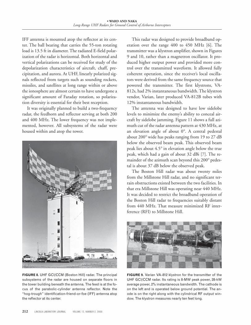
FIGURE 8. UHF GCI/CCM (Boston Hill) radar. The principalsubsystems of the radar are housed on separate floors inthe tower building beneath the antenna. The feed is at the fo-cus of the parabolic-cylinder antenna reflector. Note the“hog-trough” identification-friend-or-foe (IFF) antenna atopthe reflector at its center.
IFF antenna is mounted atop the reflector at its cen-ter. The ball bearing that carries the 55-ton rotatingload is 13.5 ft in diameter. The radiated E-field polar-ization of the radar is horizontal. Both horizontal andvertical polarizations can be received for study of thedepolarization characteristics of aircraft, chaff, pre-cipitation, and aurora. At UHF, linearly polarized sig-nals reflected from targets such as sounding rockets,missiles, and satellites at long range within or abovethe ionosphere are almost certain to have undergone asignificant amount of Faraday rotation, so polariza-tion diversity is essential for their best reception.
It was originally planned to build a two-frequencyradar, the feedhorn and reflector serving at both 200and 400 MHz. The lower frequency was not imple-mented, however. All subsystems of the radar werehoused within and atop the tower.
This radar was designed to provide broadband op-eration over the range 400 to 450 MHz [6]. Thetransmitter was a klystron amplifier, shown in Figures9 and 10, rather than a magnetron oscillator. It pro-duced higher output power and provided more con-trol over the transmitted waveform. It allowed fullycoherent operation, since the receiver’s local oscilla-tors were derived from the same frequency source thatpowered the transmitter. The first klystrons, VA-812s, had 2% instantaneous bandwidth. The klystronvendor, Varian, later produced VA-812B tubes with12% instantaneous bandwidth.
The antenna was designed to have low sidelobelevels to minimize the enemy’s ability to conceal air-craft by sidelobe jamming. Figure 11 shows a full azi-muth cut of the radar antenna pattern at 430 MHz, atan elevation angle of about 0°. A central pedestalabout 200° wide has peaks ranging from 19 to 27 dBbelow the observed beam peak. This observed beampeak lies about 4.5° in elevation angle below the truepeak, which had a gain of about 32 dBi [7]. The re-mainder of the azimuth scan beyond this 200° pedes-tal is about 37 dB below the observed peak.
The Boston Hill radar was about twenty milesfrom the Millstone Hill radar, and no significant ter-rain obstructions existed between the two facilities. Inthat era Millstone Hill was operating near 440 MHz.It was decided to restrict the broadband operation ofthe Boston Hill radar to frequencies suitably distantfrom 440 MHz. That measure minimized RF inter-ference (RFI) to Millstone Hill.
FIGURE 9. Varian VA-812 klystron for the transmitter of theUHF GCI/CCM radar. Its rating is 8-MW peak power, 28-kWaverage power, 2% instantaneous bandwidth. The cathode ison the left and is operated below ground potential. The an-ode is on the right along with the cylindrical RF output win-dow. The klystron measures nearly ten feet long.

• WARD AND NAKALong-Range UHF Radars for Ground Control of Airborne Interceptors
VOLUME 12, NUMBER 2, 2000 LINCOLN LABORATORY JOURNAL 213
There was justifiable concern about placing a UHFground/air communication terminal (an importantpart of the SAGE system concept) at the same site as alarge VHF or UHF radar such as the AN/FPS-24 orAN/FPS-35. The Boston Hill radar provided a goodexperimental facility for the investigation of these po-tential RFI problems.
A number of radar-evaluation, antijam, and CCMtechniques were tested at Boston Hill. We briefly dis-cuss seven of them.
Determining a Radar’s Detection-Range Capability
Directly measuring the performance of a high-capa-bility radar against a small airborne target can be diffi-cult because of horizon effects and the target’s altitudelimitations. Tests involving an F-86 fighter aircrafthad to be run at reduced transmitter power and witha 16-dB attenuator in the receiver line in order to de-termine an experimental value for the detectionrange. These results were then scaled to the conditionof full transmitter power and no receiver attenuator.Figure 12 shows the radar’s coverage diagram.
Adapting Sea-Clutter-Cancellation Techniques
Consider a cloud of chaff in an environment of con-stant-velocity winds, observed by a ground-based ra-dar. The echo signals from this cloud behave in some
ways like the sea-clutter returns seen by an airborneradar. The Time-Averaged Clutter-Coherent Air-borne Radar (TACCAR) AMTI system succeeded inreducing sea clutter by causing the zero-responsenotch of the IF velocity filter to track the radial com-ponent of sea-surface velocity relative to the airborneplatform (see the article “Displaced-Phase-CenterAntenna Technique,” by Charles Edward Muehe andMelvin Labitt, in this issue). The sliding-notch IFcanceler (SNIFCAN), developed for the Boston Hillradar, was an application of the same idea to reduceechoes from chaff, and it was tested at the Boston Hillradar.
Chaff-Canceling Techniques
A fully coherent frequency-hopping radar can over-come the frequency sensitivity of the motions of achaff cloud by making the radar echoes noncoherent.Just after the chaff bundle is dispensed by an enemyaircraft the echo from it looks like that from a strongpoint target, but as time passes the chaff slows downand disperses in position and in velocity. The echofrom it in each of the radar’s resolution volumes be-comes weaker and noiselike. The radar’s problemthen becomes that of detecting the echo signal fromaircraft targets immersed in the noisy echoes from thechaff cloud.
FIGURE 10. Dummy RF load for the transmitter of the UHFGCI/CCM radar. The transmitter is on the floor below; therotary joint and antenna mount are on the floor above. Awaveguide switch allows for operating with the dummy load(right) or the antenna (upstairs). For scale reference, eachfloor tile measures 9 × 9 in.
FIGURE 11. An azimuth cut at an elevation angle of about 0°through the 430-MHz antenna pattern of the Boston Hill ra-dar. A central region about 200° wide contains peaks rang-ing from 19 to 27 dB below the observed beam peak. This ob-served beam peak lies about 4.5° in elevation angle belowthe true peak, which had a gain of about 32 dBi.
0
–70
–60
–50
–40
–30–20–10
Rel
ativ
e si
gnal
leve
l (dB
)
Angle (deg)
Peak of beam
–200 –160 –120 –80 –40 0 40 80 120 160 200

• WARD AND NAKALong-Range UHF Radars for Ground Control of Airborne Interceptors
214 LINCOLN LABORATORY JOURNAL VOLUME 12, NUMBER 2, 2000
The broadband characteristics of the Boston Hillradar made it practical to demonstrate the efficacy ofpulse-to-pulse frequency hopping in the minimiza-tion of echoes from distributed targets such asweather and chaff.
More about Pulse-to-Pulse Frequency Hopping
Pulse-to-pulse frequency hopping has the further ad-vantage of transforming ground-clutter echoes intonoiselike signals also, unless a particular piece of clut-ter corresponds to a large physical point target. Ofcourse, frequency hopping adds complexity to theradar’s MTI circuitry.
The incorporation of frequency coding in the fre-quency-hopping pattern made pulse-interval expan-sion possible at the Boston Hill radar. A target (a mis-
sile, for example) in a distant and specific interpulserange interval could be detected without its having tocompete with echo signals from targets in other inter-vals. The addition of instantaneous-frequency-corre-lation (IFC) constant-false-alarm-rate (CFAR) cir-cuitry to the radar’s frequency-hopping receivergreatly reduced or eliminated the echoes fromweather and chaff. The echoes from auroral ioniza-tion were also reduced, but it was found that pulse-to-pulse frequency hopping was not necessary; the rela-tively simple IFC CFAR circuitry sufficed.
Jittered Pulse-Repetition Frequency
The Boston Hill radar was capable of jittering itspulse-repetition frequency (PRF). That CCM tech-nique can be employed to prevent a pulse-repeaterjammer, carried by an aircraft, from jamming echoesfrom targets that are closer to the radar than it is.Outside that range the repeated pulse signals fall intothe same range box as the authentic signals when re-ceived at the radar. Inside that range they fall intorandomly distributed range boxes, depending on howthe PRF jitter is programmed. They do not simulateechoes from a nonexistent aircraft, so they cause lessconfusion to the radar signal processing circuitry.
Sidelobe Cancellation, Jammer-Strobing Systems
A system installed in the Boston Hill radar could in-dicate unambiguously the azimuth (or “strobe”) of ajammer, even when the latter was within its self-screening region. The operating principle involvedcomparing the signal received by an omnidirectionalantenna with the signal received by the main radarantenna. The output of the system was a PPI strobe,of angular width roughly equal to the antenna beam-width at its sidelobe level, pointing directly towardthe azimuth of the jammer. This system was an out-growth of Lincoln Laboratory’s Project Cross Over. Itwas satisfactorily tested in the course of several U.S.Air Force jamming exercises.
Another jammer-strobing method was developedin the course of Lincoln Laboratory’s program to de-velop electronic counter-countermeasures for AEWradars. This method requires only a Clark/Dicke-FixIF channel in the radar receiver and provisions for in-serting pulsed RF signals ahead of it. For a discussion
FIGURE 12. Boston Hill UHF radar coverage diagram on anF-86 fighter aircraft for 50% blip-scan ratio (the radar opera-tor on average sees the blip every other scan). The radio ho-rizon is 4/3 the radius of the earth.
Slant range (nmi)
Hei
ght (
103 fe
et)
Radar
2°
0.5°1°
3°4°
5°6°7°8°9°10
°12°15°20°60° Elevation angle (deg)
0°
30°
80 160 240 320 400 4800
0
40
80
120
160
200
240
280
320
360
400
440
480

• WARD AND NAKALong-Range UHF Radars for Ground Control of Airborne Interceptors
VOLUME 12, NUMBER 2, 2000 LINCOLN LABORATORY JOURNAL 215
of the Dicke Fix, a counter-countermeasure, see thearticle entitled “Early Advances in Radar Technologyfor Aircraft Detection,” by Donald L. Clark, in thisissue. Comparison of the two jammer-strobing meth-ods revealed essentially the same basic limitations forboth.
Observing Objects in Space
An interesting experiment was carried out on 29 Oc-tober 1959, when NASA launched a 100-ft-diametermetallized-plastic balloon called Shotput 1 on asounding rocket from Wallops Island, Virginia, some400 to 500 miles south of Boston Hill. The balloonwas inflated after launch. This preliminary test wasfollowed by the successful launch to orbit of the Echo1 balloon from Cape Canaveral, Florida, on 12 Au-gust 1960. In the Shotput 1 test, the balloon rose to anelevation angle of about 25°, as seen from the radar,and it could be seen with the naked eye. The echoesfrom it were strong. The signals dropped out duringthe higher-altitude portions of the balloon’s flight,probably because it had then risen above the mainlobe of the radar’s antenna pattern. The signals reap-peared a few minutes later, when the balloon fell backinto the antenna beam. The Boston Hill radar alsosupported NASA’s Shotput 2 test on 16 January 1960.This radar was not well suited to the observation oforbiting satellites; attempts to detect them were un-successful.
The Boston Hill radar reached its full operatingcapability in late 1959, just about the time whenLincoln Laboratory changed the thrust of its radarprograms. Although by no means had all of the prob-lems presented by airborne threats been solved,Lincoln Laboratory’s efforts in radar research and de-velopment were to be concentrated on ballistic mis-sile threats until the late 1960s. At that time LincolnLaboratory began its FAA-sponsored program in airtraffic control. Also at that time there was resurgenceof interest in tactical radar applications, engenderedby the Vietnam War. These two disparate influencesled to the broad range of radar technology that ischronicled in other articles in this issue of the LincolnLaboratory Journal.
On 1 April 1960 responsibility for the Boston Hillradar was transferred to the MITRE Corporation,
just as was done earlier for the Jug Handle Hill radar.Several years later the antenna of the Boston Hill ra-dar was demounted and used to replace an AN/FPS-35 antenna that had been damaged by high winds atan operational Air Force site. One of the authors, vis-iting Boston Hill in the early 1990s, found the towerstill standing. It, like the tower of the Jug Handle Hillradar (Figure 6), had become an antenna farm.
Acknowledgments
Much of the information for the sidebar was drawnfrom “History of the Rome Air Development Cen-ter,” Griffiss Air Force Base, New York, 1 January to31 December 1959, Document 60-14627, pp. 51–55. This document and others that were graciouslyprovided by Thomas W. Thompson, Chief Historianat the Rome Research Site, New York, were invalu-able. Frank Mastrovita, archivist at the Bedford, Mas-sachusetts, operation of the MITRE Corp., helpedthe authors follow the trails of the Jug Handle Hilland Boston Hill radars after they were transferredfrom Lincoln Laboratory to MITRE. It is a pleasureto acknowledge their generous assistance.
R E F E R E N C E S1. J.R. Zacharias and A.G. Hill, Final Report of 1952 Summer
Study Group, vol. 2, Lincoln Laboratory (10 Feb. 1953).2. “Five Years at the Radiation Laboratory,” 1991 IEEE MTT-S
Int. Microwave Symp., Boston, 10–14 June 1991 (originallypublished 1946).
3. R. Buderi, The Invention That Changed the World: How a SmallGroup of Radar Pioneers Won the Second World War andLaunched a Technological Revolution (Simon & Schuster, NewYork, 1996).
4. J. Aarons, “Antenna and Receiver Measurements by Solar andCosmic Noise,” Proc. IRE 42 (5), 1954, pp. 810–815.
5. P.A. Northrop, “Boston Hill UHF Radar,” Technical Report243, Lincoln Laboratory ( 6 July 1961), DTIC #AD-325634.
6. The Jug Handle Hill radar was narrowband but tunable overthe same frequency range.
7. The nose of the antenna beam was designed to be about 4.5°above the local horizontal at the radar, to improve its coverageof airborne targets.

• WARD AND NAKALong-Range UHF Radars for Ground Control of Airborne Interceptors
216 LINCOLN LABORATORY JOURNAL VOLUME 12, NUMBER 2, 2000
. was born in Texas in 1924.During World War II, heserved in the U.S. Army SignalCorps, where he installed,maintained, and repairedcryptographic equipment inthe Pacific Theater of Opera-tions. He received a B.S.degree from Texas A&MCollege, and M.S. and Ph.D.degrees from California Insti-tute of Technology, all inelectrical engineering. In 1952,he joined Lincoln Laboratory,where his first thirteen yearswere devoted to radar systemengineering, including air-borne-early-warning andground-based surveillanceradars, and space tracking andrange instrumentation forNASA’s Project Mercury andfor ballistic missile testing. In1965 he switched from strug-gling to solve problems thatinvolve (range)–4 to working onmore tractable problems involving(range)–2. That work has beenin space communication,primarily in the developmentof systems that serve the di-verse needs of the military andcivil user communities bymeans of reliable links throughsatellites. He has helped todesign, build, test, and operatein orbit Lincoln ExperimentalSatellites 5, 6, 8, 9, and twoEHF Packages carried by host
satellites FLTSATs 7 and 8. Hehas also contributed to thedevelopment of the operationscenters associated with thesesatellites. Being blessed with aretentive memory, and havingthe collecting habits of a packrat, he helped to prepare MITLincoln Laboratory: Technologyin the National Interest, anillustrated history of the Labo-ratory published in 1995. Heretired from Lincoln Labora-tory in 1994 after long serviceas manager of Satellite Opera-tions (“Keeper of Old Satel-lites”). He now putters aroundwith a few old satellites thatrefuse to die, consults, writes,lectures, and raises vegetablesin the summertime. He is aregistered professionalengineer in Massachusetts, amember of several professionalsocieties, and currently aDistinguished Lecturer for theIEEE Aerospace and Elec-tronic Systems Society.
. joined Project Lincoln in June1951 after completing hisDoctor of Science degree(electron optics) at HarvardUniversity. In 1954 Dr. Nakabecame associate leader of theSpecial Radars group. In 1956he became the leader of theHeavy Radars group, where heled the development of theBoston Hill radar and was amember of the Air Force’sFrequency Diversity Advisorygroup. In 1959 Bob joined theMITRE Corporation, whichhad been established a yearearlier to head the RadarSystems and Techniques de-partment. Subsequently hebecame associate technicaldirector, then technical direc-tor of MITRE’s Applied Sci-ence Laboratories. In 1969Bob became chief scientist ofthe MITRE Corporation.That same year, he reported tothe Pentagon to becomedeputy director of the Na-tional Reconnaissance Office.In 1972 he joined Raytheon tobe director of Detection andInstrumentation Systems, andin 1975 returned to the Penta-gon to become Air Force chiefscientist. In 1978 he joinedScience Applications, Inc. ascorporate vice president, andin 1982 he joined GTE Gov-ernment Systems Corporation
as vice president, Engineeringand Planning, from which heretired in 1988. He now runs asmall business, CERA, Inc.,specializing in electromagnetictechnology, as its president. Heis a registered professionalengineer in Massachusetts.Bob’s honors include Memberof the National Academy ofEngineering, Fellow of theExplorers Club, and memberof the honorary societiesSigma Xi, Tau Beta Pi, and theDruids (Omicron DeltaKappa) of the University ofMissouri. He has received theU.S. Air Force’s ExceptionalService Award four times. TheUniversity of Missouri be-stowed an Honor Award forEngineering and the FacultyAlumni Award.