Logic 7: Dedicated Control Surface Support (Manual)
192
Logic 7 Dedicated Control Surface Support
Transcript of Logic 7: Dedicated Control Surface Support (Manual)

Logic 7Dedicated Control Surface Support

Apple Computer, Inc.© 2004 Apple Computer, Inc. All rights reserved.
Under the copyright laws, this manual may not be copied, in whole or in part, without the written consent of Apple. Your rights to the software are governed by the accompanying software licence agreement.
The Apple logo is a trademark of Apple Computer, Inc., registered in the U.S. and other countries. Use of the “keyboard” Apple logo (Option-Shift-K) for commercial purposes without the prior written consent of Apple may constitute trademark infringement and unfair competition in violation of federal and state laws.
Every effort has been made to ensure that the information in this manual is accurate. Apple Computer, Inc. is not responsible for printing or clerical errors.
Apple Computer, Inc.1 Infinite LoopCupertino, CA 95014-2084408-996-1010www.apple.com
Apple, the Apple logo, Aqua, Final Cut, Final Cut Pro, FireWire, iBook, iMac, iPod, iTunes, Logic, Mac, Macintosh, Mac OS, PowerBook, Power Mac, Power Macintosh, and QuickTime are trademarks of Apple Computer, Inc., registered in the U.S. and other countries.
Finder and GarageBand are trademarks of Apple Computer, Inc.
AppleCare is a service mark of Apple Computer, Inc.
Helvetica is a registered trademark of Heidelberger Druckmaschinen AG, available from Linotype Library GmbH.
Other company and product names mentioned herein are trademarks of their respective companies. Mention of third-party products is for informational purposes only and constitutes neither an endorsement nor a recommendation. Apple assumes no responsibility with regard to the performance or use of these products.

1 Contents
Preface 7 What Is Covered7 CM Automation Motormix7 CM Labs Motormix7 Emagic Logic Control8 Emagic Logic Control XT8 Mackie Baby HUI8 Mackie C48 Mackie Control8 Mackie Control Extender9 Mackie Control Universal9 Mackie HUI9 Radikal Technologies SAC-2.29 Radikal Technologies SAC-2k9 Roland SI-249 Tascam FE-89 Tascam FW-1884
10 Tascam US-22410 Tascam US-42810 Yamaha 01V9610 Yamaha 02R9610 Yamaha 01X10 Yamaha DM100011 Yamaha DM2000
Chapter 1 13 Logic Control—Basics13 Introduction14 Getting Started17 View Modes21 The Displays23 About Alert Messages24 Tips
3
4
Chapter 2 27 Logic Control—Details28 The Channel Strip(s)31 The Assignment Zone46 Fader Bank Zone48 Master Fader49 Display Zone51 The Function Key Zone52 The Global View Zone52 Function Button Zone56 The Transport Zone64 The Cursor/Zoom Key Zone65 The Jog/Scrub Wheel Zone65 Functions and Menus
Chapter 3 75 Mackie C475 V-POTs, V-SELECTs78 Buttons at Bottom80 Marker Overlay80 Track Overlay80 Channel Strip Overlay81 Function Overlay83 Assignment Overview
Chapter 4 85 Tascam FW-188485 Introduction85 Requirements85 Set Up85 Operation86 Assignment Overview
Chapter 5 91 Mackie HUI91 Requirements91 Set Up91 Other HUI-compatible Devices92 Assignment Overview
Chapter 6 103 Mackie Baby HUI103 Requirements103 Assignment Overview
Chapter 7 107 Yamaha DM2000107 Requirements107 Set Up108 Assignment Overview
Contents

Chapter 8 117 Yamaha DM1000117 Requirements117 Set Up118 Assignment Overview
Chapter 9 125 Yamaha 02R96125 Requirements125 Set Up126 Assignment Overview
Chapter 10 131 Yamaha 01V96131 Requirements131 Set Up132 Assignment Overview135 Selected Channel135 Data Entry Section135 Channel Strips135 Stereo Channel Strip136 USER DEFINED KEYS Section
Chapter 11 139 CM Labs Motormix139 Requirements139 Set Up139 Assignment Overview
Chapter 12 147 Radikal Technologies SAC-2K147 Requirements147 Set Up147 Assignment Overview153 Troubleshooting
Chapter 13 155 Roland SI-24155 Requirements155 Set Up155 Assignment Overview
Chapter 14 161 Tascam US-428161 Requirements161 Assignment Overview
Appendix A 165 Logic Control—Specifications165 Logic Control (Base Unit)167 Logic Control XT (Extension Unit)
Contents 5

6
Appendix B 169 Logic Control—MIDI Implementation169 SysEx Message Header170 Global Control Messages172 Common Control Messages
Appendix C 181 Logic Control—Control Surface Layout and IDs
Appendix D 185 Logic Control—MIDI Implementation Chart
Index 187
Contents

Pref
ace
What Is Covered
This manual covers Logic’s dedicated control surface support. Please read it thoroughly to make the most of your new controller(s).
Logic comes with dedicated support for certain control surface models. There are several plug-ins which are are a part of Logic. Some plug-ins support multiple similar control surface models.
You can use any combination of control surfaces with Logic. However you get the most out of them when using them in a Control Surface Group if they are all supported by the same plug-in.
Here you find an alphabetic list of the supported control surfaces, how they differ from similar devices and a cross reference to the relevant sections.
CM Automation MotormixOnly available in Logic Pro, not in Logic Express.
See section “CM Labs Motormix” on page 133.
CM Labs MotormixOnly available in Logic Pro, not in Logic Express.
See section “CM Labs Motormix” on page 133.
Emagic Logic ControlIf you have installed Mackie’s firmware version 1.0.2 or higher, make sure that the Logic Control runs in Logic Control mode. See sections “Logic Control—Basics” on page 13 and “Logic Control—Details” on page 26.
Also see the Appendix for more details.
7

8
Emagic Logic Control XTThis is the extension unit for the Logic Control. It has only the channel strip section; therefore it is not useful without a Logic Control.
If you have installed Mackie’s firmware version 1.0.2 or higher, make sure that the Logic Control XT runs in Logic Control mode.
See sections “Logic Control—Basics” on page 13 and “Logic Control—Details” on page 26.
Also see the Appendix for more details.
Mackie Baby HUIOnly available in Logic Pro, not in Logic Express.
The Baby HUI is a stripped-down version of the HUI. For easier navigation, we have documented it in a separate section.
See section “Mackie Baby HUI” on page 98.
Mackie C4The Logic Control plug-in has been extended for dedicated support for the Mackie C4. Please see section “Mackie C4” on page 73.
Mackie ControlThe original Mackie Control is similar to the Logic Control in hardware, however the silk screening is different. You should request a Logic Control Lexan Overlay from Mackie to get the correct silk screening. See http://www.mackie.com/products/mackiecontrol/mackiecontrol_overlay.html
Firmware version 1.0.2 or higher is required, and it must be switched to Logic Control mode.
See sections “Logic Control—Basics” on page 13 and “Logic Control—Details” on page 26.
Mackie Control ExtenderFirmware version 1.0.2 or higher is required, and it must be switched to Logic Control mode. See the documentation from Mackie on how to switch to Logic Control mode.
See sections “Logic Control—Basics” on page 13 and “Logic Control—Details” on page 26.
Preface What Is Covered

Mackie Control UniversalThe Mackie Control Universal must be switched to Logic Control mode. See the documentation from Mackie on how to switch to Logic Control mode.
See sections “Logic Control—Basics” on page 13 and “Logic Control—Details” on page 26.
Mackie HUIOnly available in Logic Pro, not in Logic Express.
The HUI plug-in has been tested with the original Mackie HUI. There are other control surfaces not mentioned here which can emulate the HUI, however we haven’t tested this and don’t support them.
See section “Mackie HUI” on page 87.
Radikal Technologies SAC-2.2Only available in Logic Pro, not in Logic Express.
There is a dedicated plug-in for the SAC-2.2/2k’s native mode.
The Logic Control plug-in detects an SAC-2.2 reacting in Logic Control emulation and ignores it, to avoid that the SAC-2.2 is installed twice.
See section “Radikal Technologies SAC-2K” on page 140.
Radikal Technologies SAC-2k
See section “Radikal Technologies SAC-2K” on page 140.
Roland SI-24See section “Roland SI-24” on page 146.
Tascam FE-8Extension unit for FW-1884.
See section “Tascam FW-1884” on page 82.
Tascam FW-1884See section “Tascam FW-1884” on page 82.
Preface What Is Covered 9

10
Tascam US-224A stripped-down version of the US-428, with dedicated support in the US-428 plug-in.
See section “Tascam US-428” on page 151.
Tascam US-428See section “Tascam US-428” on page 151.
Yamaha 01V96Only available in Logic Pro, not in Logic Express.
The Yamaha 01V96 emulates two HUI units, using two virtual MIDI In and Out connections over its USB cable.
See section “Yamaha 01V96” on page 125.
Yamaha 02R96Only available in Logic Pro, not in Logic Express.
The Yamaha 02R96 emulates three HUI units, using three virtual MIDI In and Out connections over its USB cable.
See section “Yamaha 02R96” on page 119.
Yamaha 01XThe Yamaha 01X emulates a Logic Control, however it does not have all of its controls. Please refer to the 01X documentation for details.
Logic recognizes the 01X as such and shows a custom icon, however the remaining communication is as with a Logic Control.
See sections “Logic Control—Basics” on page 13 and “Logic Control—Details” on page 26.
Yamaha DM1000Only available in Logic Pro, not in Logic Express.
The Yamaha DM1000 emulates two HUI units, using two virtual MIDI In and Out connections over its USB cable.
See section “Yamaha DM1000” on page 111.
Preface What Is Covered

Yamaha DM2000Only available in Logic Pro, not in Logic Express.
The Yamaha DM2000 emulates three HUI units, using three virtual MIDI In and Out connections over its USB cable.
See section “Yamaha DM2000” on page 101.
Preface What Is Covered 11


1
1 Logic Control—Basics
Introduction
Using a mouse and computer keyboard to do things normally done on an analog mixer can be disconcerting. Clicking an onscreen fader or knob, and dragging the mouse to achieve a silky smooth fade or pan move is difficult, if not impossible, for many users.
Logic Control provides you with hands-on control of virtually all of Logic’s real-time parameters. Move a fader and Logic’s on-screen fader will move with it. Similarly, when you make a fader move on-screen, the Logic Control fader moves. Adjust EQ by turning one of Logic Control’s V-POT knobs and Logic will update instantly. In fact, what used to take multiple mouse-clicks and/or key presses can now be achieved with the push of a button, the turn of a knob or a quick fader movement.
You can use Logic Control to:• control all transport functions• adjust MIDI, audio instrument, bus, master and audio channel volume and pan levels• control channel EQ parameters• select and control all effect and audio instrument parameters• select, solo, mute and arm tracks• set and adjust send parameters• remotely switch between screensets• scrub MIDI and audio• zoom in on individual tracks• create, delete and move between markers, and much more.
The Logic Control XT expands on the number of tracks, parameters etc. that can be controlled with individual faders, knobs and switches. The XT units are basically identical to the channel strip section (fader, V-POT, and LCD) of the Logic Control unit. You may add as many XT units as you wish to your Logic system, provided enough MIDI in and out ports are available.
13
14
All of your fader and V-POT moves can be recorded and will faithfully play back in real-time. As the Logic Control units are equipped with motorized faders, remote controlled buttons, knobs and LEDs, your automation data will be reflected on the Logic Control’s surface instantly. This keeps you completely informed about all levels—for tracks, pan, parameters, EQs etc.
The feedback you receive on the 2 row, by 55 character LCD is so good, in fact, that you may find you rarely look at your computer monitor. This facility may also be particularly useful in situations where computer fan noise is an issue; a common problem for project studios not equipped with a vocal booth. This allows you to isolate, and remotely control, your Logic system while singing or performing acoustically in another room.
For live use, the Logic Control units are ideal. The performing musician now need only take a laptop, equipped with suitable audio and MIDI interfaces (Emagic EMI 2|6 and MT4, for example), a keyboard and a Logic Control to a live event. The backlit LCD is ideal for darkened stage use. The largely metal construction, Penny and Giles™ faders and solid buttons and switches are built to withstand the rigors of touring.
Given that Logic’s Track Automation facilities can be active, even when not in record mode, you can capture your “live” realtime changes for later recall. This ensures that you’ll never again lose that “once-in-a-lifetime” performance—on stage or in the studio.
We have every confidence that the Logic Control system will provide you with many years of inspiration, fun, reliability and productivity.
Your Logic media production environment will never be the same!
Getting StartedTo make use of the Logic Control unit, you will require:• an installed copy of Logic Pro7 or Logic Express 7• a free MIDI in and out port for each Logic Control or Logic Control XT unit, on any
suitable MIDI interface, e. g. if using a Unitor 8 or AMT 8, which feature 8 MIDI in and 8 MIDI out ports, with one Logic Control and one Logic Control XT, you will need to use 2 of the Unitor8/AMT8’s MIDI ins and 2 of its MIDI outs.
A “suitable” MIDI interface features drivers which support SysEx communication. Please consult the documentation that shipped with your MIDI interface.
The number of units which can be run simultaneously is dependent on the availability of free MIDI in and out ports in your MIDI system. In a “standard” setup, a single Logic Control unit will be used alone, or accompanied by one or more Logic Control XT units. It is also possible to make use of several Logic Control and several XT units to create Control Surface Groups, as discussed in the Logic Reference Manual.
Chapter 1 Logic Control—Basics

Connecting the Unit(s)Connect your Logic Control and/or Logic Control XT units as shown in the diagram below.
As mentioned above, each Logic Control or Logic Control XT unit must have a discrete MIDI in and MIDI out connection. Do not “daisy-chain” other MIDI devices via MIDI THRU to the MIDI in or out ports used by the Logic Control units as this may result in data errors.
About the Power Supply Unit (PSU)The PSU which came with your Logic Control unit is rated at 7.5V, 4.0 Amps, with a positive tip. Do not use any other power supply with the Logic Control units as this may result in permanent damage. Any attempt to use another power supply with either unit will automatically void your warranty.
Should you have a problem with the power supply unit, immediately disconnect it from the Logic Control and wall socket to avoid damage or electrical shock. There are no user-serviceable parts in the power supply unit (or the Logic Control units). If you have a problem with your Logic Control or power supply unit, please contact the local Emagic distributor in your region or territory.
Optional Footswitches and pedalsYou may use optional foot switches to remotely control the start/stop and other functions of the Logic Control. This may be useful for guitarists or other two-handed playing. The foot switch sockets can use momentary foot pedals with either a positive or negative polarity. By default:• USER SWITCH A is assigned to Start/Stop.• USER SWITCH B is assigned to Record (note that a track must be selected and armed
for recording to take place),
Computer MIDI Interface
Optional Footswitches
Chapter 1 Logic Control—Basics 15

16
• EXTERNAL CONTROL is assigned to the MASTER fader level. Only use an expression pedal with this socket.
The polarity of the foot switches is determined by the Logic Control when powered up. Therefore it is useful to first connect the foot switches, then power up.
Power UpOnce everything is connected, press the power switch found to the rear left of your Logic Control and Logic Control XT units. Once powered, the displays will illuminate and the LCD will display a welcome message. Of note is the firmware version number found in the bottom right hand corner of the display. Each fader will slide to the top, and back to the bottom, of its travel. This self-diagnostic power-on procedure indicates that your Logic Control units are functioning correctly.
Your computer and MIDI interface can be powered up before or after the Logic Control units. Logic can be launched either before or after the units have completed initialization.
About Software and FirmwareThe Logic Control and Logic Control XT units have no “intelligence” of their own. Their functionality is host software-based, making them completely reliant on Logic to tell them what to do/how to behave. What this means is that the Logic Control cannot perform any function that Logic itself cannot do. It also means that if Logic is not booted, the Logic Control units will do nothing at all.
The plus side of this approach is that the units represent the ultimate in upgradable hardware. As new functions are added to Logic, Logic Control will also be able to access and control them.
The Logic Control units do, however, have a form of software called “firmware”. This firmware is much like the BIOS found in your computer. New “behaviors”—at a hardware level—such as an improved control of the fader servo motors and changes to the display can be made via firmware updates.
The firmware is stored on an EEPROM (Electronically Erasable Programmable Read Only Memory) chip. It can be updated via a simple MIDI dump procedure, in the form of a MIDI file.
Should new firmware become available, you can simply download the appropriate MIDI file and play it to your Logic Control unit(s), which will be updated accordingly. The steps required to perform a firmware update will be outlined in the readme file which accompanies the file. Please read this before attempting any update.
Chapter 1 Logic Control—Basics

Quick Start Once Logic is launched, any connected (and powered) Logic Control units will automatically be detected. The LCD above the V-POTs will indicate the tracks (shown from left to right) as they appear—from top to bottom—in the Arrange window Track List of your Autoload song. The two character Mode Display will display Pn, the Position/Time Display will display 1 1 1 1, assuming that your Autoload song starts at this position.
Please note that if running multiple units, the order of channels/tracks (from left to right) needs to be defined. The easiest way to do this is to launch Logic, and then switch on the units from left to right, with a delay of about 5 seconds between powering up each unit. This only needs to be done once—and the setup will automatically be created in the right order. Once the setup is defined, the order in which you power up Logic or the Logic Control units doesn’t matter.
Should your Autoload song have the Cycle mode enabled or muted objects etc., the corresponding LEDs on the Logic Control will be illuminated to reflect each track’s current status.
It should be noted that the default settings and displays indicated above may be slightly different on your unit. The reasons for any such differences include: Firmware changes, software changes and user changes.
If the auto-detection phase completed correctly, you’re ready to go! If not, see the Logic user manual for setup information.
Although the Logic Control is intuitive to use, the following sections will provide you with information on accessing parameters and functions that may not be apparent at first glance. Feel free to use them as a reference manual while experimenting.
View ModesBefore taking a look at the front panel of the Logic Control, we’d like to cover a simple—but very important—concept.
Logic Control works in three discrete View modes.• Mixer View—layout like in the Track Mixer window (Global switch off ).• Global View—layout like in the Track Mixer window (Global switch on).• Arrange View—layout like in the Arrangement window.
These modes are mutually exclusive, so if you’re in one View mode, you cannot be in the other.
It is important to note that the Mixer vs. Global View modes is a property of the Control Surface Group, not a global setting. So one group can display the busses, while the other shows tracks, for example.
Chapter 1 Logic Control—Basics 17
18
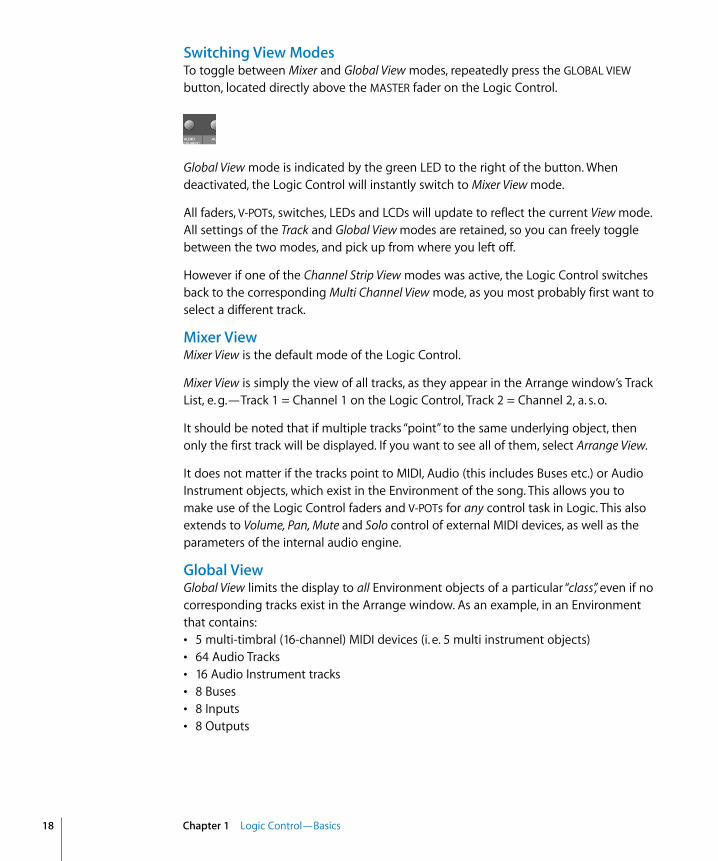
Switching View ModesTo toggle between Mixer and Global View modes, repeatedly press the GLOBAL VIEW button, located directly above the MASTER fader on the Logic Control.
Global View mode is indicated by the green LED to the right of the button. When deactivated, the Logic Control will instantly switch to Mixer View mode.
All faders, V-POTs, switches, LEDs and LCDs will update to reflect the current View mode. All settings of the Track and Global View modes are retained, so you can freely toggle between the two modes, and pick up from where you left off.
However if one of the Channel Strip View modes was active, the Logic Control switches back to the corresponding Multi Channel View mode, as you most probably first want to select a different track.
Mixer ViewMixer View is the default mode of the Logic Control.
Mixer View is simply the view of all tracks, as they appear in the Arrange window’s Track List, e. g.—Track 1 = Channel 1 on the Logic Control, Track 2 = Channel 2, a. s. o.
It should be noted that if multiple tracks “point” to the same underlying object, then only the first track will be displayed. If you want to see all of them, select Arrange View.
It does not matter if the tracks point to MIDI, Audio (this includes Buses etc.) or Audio Instrument objects, which exist in the Environment of the song. This allows you to make use of the Logic Control faders and V-POTs for any control task in Logic. This also extends to Volume, Pan, Mute and Solo control of external MIDI devices, as well as the parameters of the internal audio engine.
Global ViewGlobal View limits the display to all Environment objects of a particular “class”, even if no corresponding tracks exist in the Arrange window. As an example, in an Environment that contains:• 5 multi-timbral (16-channel) MIDI devices (i. e. 5 multi instrument objects)• 64 Audio Tracks• 16 Audio Instrument tracks• 8 Buses• 8 Inputs• 8 Outputs
Chapter 1 Logic Control—Basics

Global View gives you direct access to the Volume, Pan, Mute and Solo parameters of all 80 MIDI channels, 64 audio tracks etc. as outlined above.
Note the light gray legend which links the GLOBAL VIEW button to the eight buttons in the “Global View” zone of the Logic Control front panel.
Simply press the button which corresponds to the object “class” that you wish to view.
You can select multiple classes by clicking on multiple buttons simultaneously.
The OUTPUTS button activates both output and master objects.
The USER button is reserved for future Logic features.
The Track Mixer window’s contents automatically follows the GLOBAL VIEW button’s state and also sets the object filters according to the object classes activated in Global View. You can disable this behavior with menu item View > Follow Control Surface.
Arrange ViewArrange View is similar to Mixer View, with one exception: Namely, if multiple tracks play back via the same environment object, all of them will be displayed on separate channel strips. This is helpful when used in conjunction with the nudge commands, for example.
Arrange View is engaged by pressing the SHIFT and GLOBAL VIEW buttons simultaneously. It is active as long as the GLOBAL VIEW button’s LED is blinking.
FoldersIn Mixer View and Arrange View, Logic Control always displays the track of a certain folder—by default those of the “root” folder, i. e. the top level folder.
Folder tracks use the instrument “Folder” which has no parameters at all. Therefore the V-SELECT is available for other purposes than setting track parameters. Pressing the V-SELECT of a folder track enters the folder.
Alternatively you can select the folder track with SELECT and enter the folder with the ENTER button.
You can leave a folder and return to the folder level above with the CANCEL button.
Chapter 1 Logic Control—Basics 19

20
The following topics cover a couple of “viewing” options that work in all View modes.
Channel ViewsThe channels section (i. e. the channel strips) can be in two fundamental view “modes”—Multi Channel and Channel Strip View. Normally, switching between these modes only affects the V-POTs, with the other channel controls always remaining in Multi Channel View.
Please note that there are some exceptions to this: in special view modes, the faders and SOLO and MUTE buttons have alternate uses/meanings.• Multi Channel View—shows one parameter for eight tracks (normally a section of the
Track Mixer window). If your Control Surface Group consists of a Logic Control and additional Logic Control XTs, you will see more than eight tracks. The section can be shifted to the next/previous group of channels with the FADER BANK buttons.
Please note that when in Multi Channel view: the display will automatically update when another FADER BANK is selected. Please read the Fader Bank Zone section on page 46.• Channel Strip View—shows eight (or more) parameters of the selected track. The
display will automatically update when another track is selected.
Switching between Multi Channel and Channel Strip views is achieved by pressing the ASSIGNMENT button whose LED flashes.
When pressing an ASSIGNMENT button which is not currently selected, the assignment mode changes, and the according Multi Channel View is activated. Exception: switching between Instrument Edit View and Plug-in Edit View.
PagesLogic features the Channel EQ with 8 (Logic Pro) or 4 (Logic Express) bands per audio channel. Each EQ has four (4) parameters. It also offers (up to) 16 Buses. Many of Logic’s plug-ins—effects and Audio Instruments—plus those of third-party manufacturers, feature dozens of parameters.
Every one of these parameters can be accessed by the Logic Control.
To give you an example of how this works, imagine a plug-in that contains, say, 16 parameters and you are using a single Logic Control.
Once you’ve switched to the appropriate “Channel Strip Edit View” of the plug-in you wish to adjust, you can directly affect parameters 1 to 8 by using V-POTs 1 to 8. You can then switch by a “page” to access parameters 9 to 16.
Chapter 1 Logic Control—Basics
Simply press the LEFT/RIGHT CURSOR keys to step up/down to the next “page” of parameters.
The current/total number of pages (e. g. “Page 1/3”) is displayed in the top right-hand corner of the LCD whenever multiple “pages” are available—i. e. when parameter names are shown in the lower row.
To get to the first or last page, hold down OPTION while pressing the LEFT/RIGHT CURSOR key.
Switching by page is just the default. To switch by a single parameter, hold down C/ALT while pressing the appropriate cursor key.
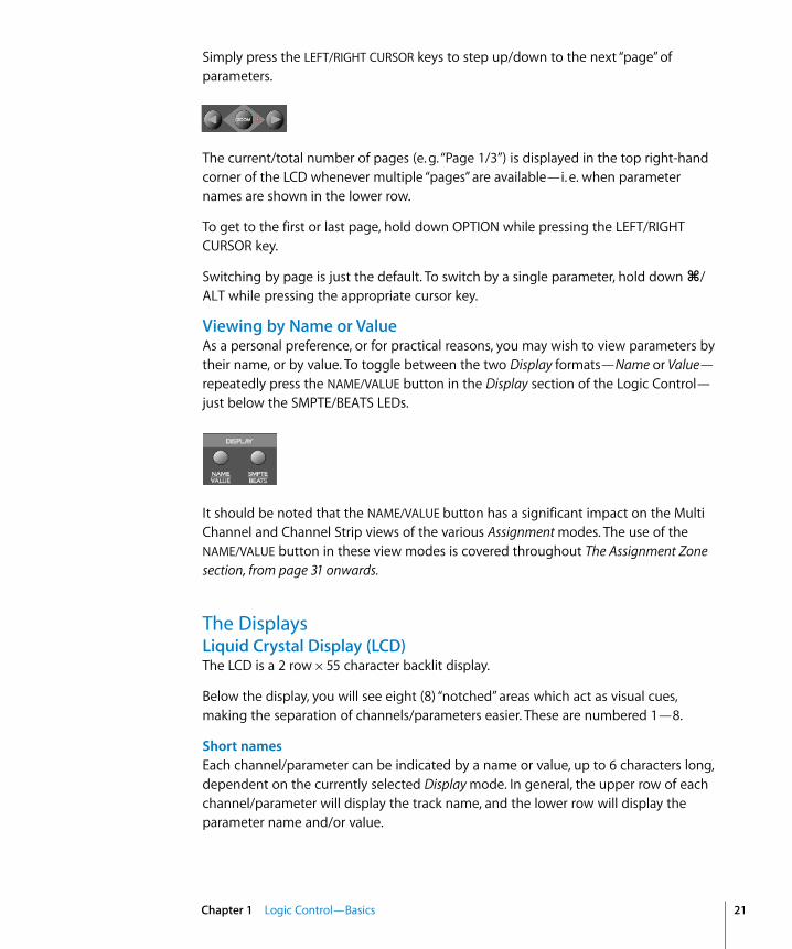
Viewing by Name or ValueAs a personal preference, or for practical reasons, you may wish to view parameters by their name, or by value. To toggle between the two Display formats—Name or Value—repeatedly press the NAME/VALUE button in the Display section of the Logic Control—just below the SMPTE/BEATS LEDs.
It should be noted that the NAME/VALUE button has a significant impact on the Multi Channel and Channel Strip views of the various Assignment modes. The use of the NAME/VALUE button in these view modes is covered throughout The Assignment Zone section, from page 31 onwards.
The DisplaysLiquid Crystal Display (LCD)The LCD is a 2 row × 55 character backlit display.
Below the display, you will see eight (8) “notched” areas which act as visual cues, making the separation of channels/parameters easier. These are numbered 1—8.
Short namesEach channel/parameter can be indicated by a name or value, up to 6 characters long, dependent on the currently selected Display mode. In general, the upper row of each channel/parameter will display the track name, and the lower row will display the parameter name and/or value.
Chapter 1 Logic Control—Basics 21

22
Note: 8-bit ASCII characters such as curly quotes and umlaut characters are replaced by the best-possible 7-bit ASCII equivalent, e. g. ä = ae, ö=oe, ü=ue, á = a, ø = oe, œ = oe, ß = ss, å = a.
In case you don’t like the way a track or instrument name is abbreviated, you can provide your own version, simply by appending it with a backslash (\). To get the track “My very long track name” displayed as “long” instead of “TrckNm”, the track name must be “My very long track name\long”.
Long namesIn some modes, a long (i. e. full) parameter or other name will be displayed briefly on-screen, when adjusted. The display of long names, and the duration of this display, is set in the Preferences. These settings are discussed in the Logic user manual.
Name vs. ValueTo toggle between the two Display formats—Name or Value—repeatedly press the NAME/VALUE button in the Display section of the Logic Control—just below the SMPTE/BEATS LEDs.
The following is a brief overview of the effect the NAME/VALUE button has on the various display modes.• Multi Channel view, display mode Names: upper line shows track names, lower line
shows parameter names• Multi Channel view, display mode Values: upper line shows track names, lower line
shows parameter values• Channel Strip view, display mode Names: upper line shows view info, lower line shows
parameter names• Channel Strip view, display mode Values: upper line shows parameter names, lower
line shows parameter values
Assignment LED (Mode Display)To the right of the LCD, you will find the two digit, seven-segment LED display which indicates the current Assignment status of the Logic Control. Throughout the manual we refer to this LED as the Mode Display.
The Assignment status is determined by the 6 buttons found in the light gray Assignment area directly below the Mode Display. We will discuss the use of these buttons, and the abbreviations shown in the LED, in The Assignment Zone section, from page 31 onwards.
Basically the display ends with a period whenever a Channel Strip View is active.
Chapter 1 Logic Control—Basics
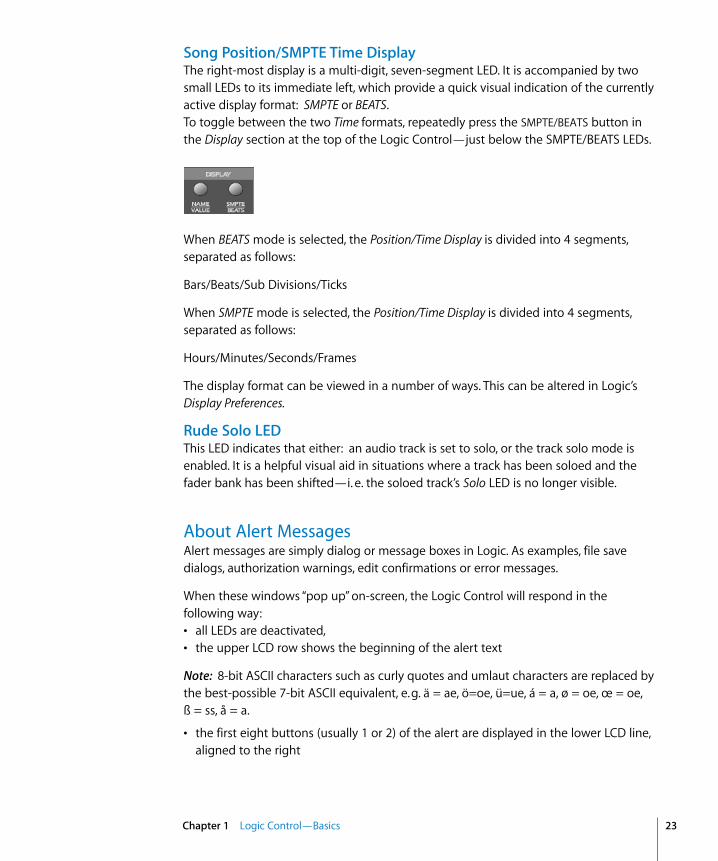
Song Position/SMPTE Time DisplayThe right-most display is a multi-digit, seven-segment LED. It is accompanied by two small LEDs to its immediate left, which provide a quick visual indication of the currently active display format: SMPTE or BEATS. To toggle between the two Time formats, repeatedly press the SMPTE/BEATS button in the Display section at the top of the Logic Control—just below the SMPTE/BEATS LEDs.
When BEATS mode is selected, the Position/Time Display is divided into 4 segments, separated as follows:
Bars/Beats/Sub Divisions/Ticks
When SMPTE mode is selected, the Position/Time Display is divided into 4 segments, separated as follows:
Hours/Minutes/Seconds/Frames
The display format can be viewed in a number of ways. This can be altered in Logic’s Display Preferences.
Rude Solo LEDThis LED indicates that either: an audio track is set to solo, or the track solo mode is enabled. It is a helpful visual aid in situations where a track has been soloed and the fader bank has been shifted—i. e. the soloed track’s Solo LED is no longer visible.
About Alert MessagesAlert messages are simply dialog or message boxes in Logic. As examples, file save dialogs, authorization warnings, edit confirmations or error messages.
When these windows “pop up” on-screen, the Logic Control will respond in the following way:• all LEDs are deactivated,• the upper LCD row shows the beginning of the alert text
Note: 8-bit ASCII characters such as curly quotes and umlaut characters are replaced by the best-possible 7-bit ASCII equivalent, e. g. ä = ae, ö=oe, ü=ue, á = a, ø = oe, œ = oe, ß = ss, å = a.
• the first eight buttons (usually 1 or 2) of the alert are displayed in the lower LCD line, aligned to the right
Chapter 1 Logic Control—Basics 23

24
• the Position/Time Display shows Message, Alert, Attention or Caution, depending on the icon in the alert
• if the alert text does not fit in the LCD’s upper row, it will start scrolling after 3 seconds. When the text has scrolled to the end, it will remain onscreen for 3 seconds and will then recommence.
You can scroll the alert text manually with the jog wheel. Once you start doing so, automatic scrolling is disabled
In addition to the Jog Wheel, all V-POTs can be used to scroll the alert text. They also show the current scroll position.• By pressing one of the V-SELECTs, you trigger the appropriate button/function in the
alert—if applicable.• The ENTER button triggers the default button in the alert, where applicable.• The CANCEL button triggers the button labelled “Cancel” or “Abort” in the alert, where
applicable.
After the alert has disappeared, all controls and displays will return to their previous state.
For other modal dialogs, only the text There is a modal dialog on the screen appears. The ENTER and CANCEL buttons don’t work in this case; you have to end the dialog with the mouse or computer keyboard.
For file select boxes, only the text There is a file select dialog on the screen appears. The ENTER and CANCEL buttons don’t work in this case; you have to end the dialog with the mouse or computer keyboard.
TipsWay back at the beginning of this manual we said “Your Logic media production environment will never be the same!”
This, as we’re sure you’re starting to realize, was not an unrealistic claim.
Logic Control changes the way you work, and is most effective if you make a few small changes to your working methods. The following is a small collection of good working practices which will help you to work more smoothly and efficiently with the Logic Control system.
Customize your Autoload Song • Set up Screensets 1—7 to your liking. These can be accessed directly via the Function
Keys—F1 to F7. Function Key 8 (F8) will close the top-most window.• We suggest that a full-screen Arrange window, with Track Automation View set to on,
is among your Screensets.• A full-screen Track Mixer window is also recommended.
Chapter 1 Logic Control—Basics

Get Into the Habit of Using MarkersNot much more can be said. Markers allow you to quickly “jump” from location to location in a “project”. The Logic Control features a number of shortcuts which allow you to rapidly switch between Markers.
Markers are very useful for the creation/selection of Cycle regions and a number of other tasks, such as Drop In and Replace.
If you tend to follow a particular song structure, or like to work in “chunks” of bars (4, 8, 16 bars etc.), then set up a number of Markers at suitable locations in your Autoload song.
Set a Default Song File Name and PathThe SAVE button on the Logic Control will automatically launch the File Save dialog. Once the song has been saved once, pressing the SAVE button will incrementally save the song without launching the File Save dialog window.
As soon Logic boots, and the Autoload song is loaded, you should make it a routine to:• create a new “project” folder, and name it• save the autoload song—with the same or a similar name to the folder—into the
“project” folder via the Save As menu option.
Set a Default Audio File Name and PathWhen an audio track is armed, Logic will ask you to specify a default file name and path. If this is done at the start of your sessions, it won’t interrupt your creative flow while recording.
After saving the Autoload—under its new name—into the “project” folder, you should make it a routine to:• press the “A” key on your computer keyboard• set a default audio file name—ideally of the same or a similar name to that of the
project/song• set the path for the audio files to the “project” folder
Once you’ve completed the Song and File Save steps, press the SAVE button on the Logic Control, and start recording.
Chapter 1 Logic Control—Basics 25


2
2 Logic Control—DetailsThis chapter will introduce you to the front panel of the Logic Control. It is assumed that you are familiar with the basic use and terminology of Logic. As such, we will not cover the functionality and uses of the individual Logic parameters themselves. Please consult your Logic reference manual or online help files, if you require further information.
LCD Assignment Display Time Display
V-POTs
Rec Rdy, Solo, Mute,and Select keys
Faders
Jog WheelCursor keys
Transport
Control Buttons
Assignment Buttons
Display Buttons
Channel Buttons
Function Keys
27

28
We strongly encourage you to press the buttons, turn the V-POT knobs etc. as you’re reading through this chapter (not that you probably need much encouragement). This will help you to get a “feel” for how the Logic Control works, and how the various parts of the control surface interact with one another.
Topics in this chapter are broken down into “Zones” of the Logic Control surface.
The Channel Strip(s)As each channel strip is identical, the information discussed in this section applies equally to all eight channel strips on the Logic Control and Logic Control XT units.
V-POT/V-SELECT This “soft” potentiometer can be used to adjust the send level and pan, plus any other parameter for EQ, instruments, effects etc. The V-POT can also be used to choose items—such as plug-ins, Audio Instruments and more—from scrollable lists, and to determine destinations for sends.
The V-POT also contains an integrated V-SELECT push button. This button generally sets a “default” parameter value (where a parameter has more than two possible values), or toggles between two parameter values (e. g on/off ). The V-SELECT can also be used to activate a function, selected through use of the V-POT. As an example, the V-POT can be rotated in order to select an effect plug-in for a particular channel Insert slot. Once the desired effect is displayed in the LCD, a simple press downwards on the top of the V-POT will activate the V-SELECT switch. In the example given, this would select, and insert, the effect and launch the plug-in window. On occasion, the V-SELECT is used to switch to a special Assignment mode.
The current value of any parameter being adjusted by the V-POT is displayed on the LCD (dependent on the NAME/VALUE setting), and is also indicated by the ring of LEDs which surround it. The various LED “ring” displays are shown here:
This will vary as follows, dependent on the selected parameter:• Connected series of LED segments from left to right (e. g. send level)• Single segment (e. g. panorama, frequency)• Connected series of LED segments, starting in the center position and fanning to the
left OR right (e. g. EQ gain)
Chapter 2 Logic Control—Details

• Series of connected LED segments, starting in the center position and fanning to the left AND right (e. g. Q-Factor)
• An LED dot below the V-POT indicates when the parameter value is in the centered/default position
Holding down the C/ALT button sets the V-POTs to high resolution parameter adjustment mode, where applicable.
Holding down the OPTION button toggles the V-POT between the minimum/maximum parameter value.
Rec/Rdy (Record/Ready) Switch This switch arms or disables the channel for recording. Each channel features an independent Rec/Rdy LED which illuminates when a track is “armed” for recording.
Holding down the OPTION button, while pressing any REC/RDY button will disarm all tracks.
In Global View, if you arm an audio channel which is currently not used by any track in the song, and then start recording, you will be asked if you want to create a new track with this audio channel in the current recording folder.
Signal LEDIndicates the presence of any outgoing MIDI or audio signal. When recording, the presence of an incoming signal will be indicated.
Solo SwitchFor isolating a channel’s signal. Each channel features an independent Solo LED which illuminates when a track is soloed. The Rude Solo LED—just to the right of the Position/Time Display LED—also illuminates whenever any track is soloed.
Chapter 2 Logic Control—Details 29

30
Holding down the OPTION button, while pressing any SOLO button will disable solo for all tracks.
In the “Send Destination/Level” views (see the Send Assignment Modes section, from page 39 onwards), the SOLO button controls the Pre/Post mode selection—in both Multi Channel and Channel Strip views.
Mute SwitchUsed to defeat the track’s signal. Each channel features an independent Mute LED which illuminates when a track is muted.
Holding down the OPTION button, while pressing any MUTE button will unmute all tracks.
In the “EQ Frequency/Gain” and “Send Destination/Level” views, the MUTE button controls the EQ bypass or Send mute function. This affects both Multi Channel and Channel Strip views.
Select Switch This switch is used to select a channel for channel-based editing or assignment commands. Each channel features an independent SELECT LED which illuminates when a track is selected.
When holding down the SHIFT button, pressing any channel SELECT button will set the track’s volume to unity level (0 dB).
While holding down SHIFT, a SELECT button’s LED indicates if the track’s volume is set to 0 dB.
When holding down the OPTION button, pressing any channel SELECT button will create a new track with the same instrument of the selected track and switch to Arrange View.
When holding down the SHIFT and OPTION buttons, pressing any channel SELECT button will create a new track with the next instrument of the selected track and switch to Arrange View.
Chapter 2 Logic Control—Details

Touch-Sensitive Motor Fader These 100mm faders are for controlling the channel’s levels. They transmit 1,024 discrete “steps” as a 10 Bit value, making their use very smooth. When FLIP is activated, the parameter currently assigned to the V-POT can be controlled with the fader. This allows you to more easily control pans, aux returns, MIDI track parameters, EQs, Plug-in, Audio Instrument or other channel parameter levels/values. Please see the Logic Reference Manual for further information. The eight faders move relative to the activity of the currently chosen Bank of on-screen faders. The Fader Bank is shifted when one of the FADER BANK buttons is pressed.
Fader Behavior in Other Modes• In Flip mode: duplicates or swaps with V-POT of same channel.• In Surround Angle/Diversity View: adjust surround diversity• In EQ Frequency/Gain View: adjust gain of selected EQ band• In Send Destination/Level Multi Channel View: adjust send level of selected send• In Send Destination/Level Channel Strip View: adjust send level of send on selected
track
The Assignment ZoneThe small light gray area just below the Mode Display contains six buttons.
These ASSIGNMENT buttons work in both Track and Global View modes. View modes are discussed in View Modes section, from page 17 onwards.
Chapter 2 Logic Control—Details 31
32
When these buttons are pressed, the Mode Display, plus the LED associated with each button, will update to reflect the currently selected assignment “mode”. The LCD will also update to display the parameters relevant to the selected Assignment. These parameters, are, of course assigned to the corresponding V-POTs.
All ASSIGNMENT buttons work as toggle switches, which means that if you click them repeatedly, they will switch between the Multi Channel and Channel Strip View modes. • Multi Channel View—you see the same parameter for multiple channels. In Multi
Channel View, the Mode Display does not show a period—e. g. P1• Channel Strip View—you see multiple parameters for a single channel. In Channel
Strip View, the Mode Display shows a period to the right—e. g. P1.
Switching between Multi Channel and Channel Strip views is achieved by pressing the selected ASSIGNMENT button multiple times.
When pressing an ASSIGNMENT button which is not currently selected, the Assignment mode changes, and the view switches to Multi Channel View. Exception: switching between Instrument Edit View and Plug-in Edit View retains Channel Strip View.
The NAME/VALUE button also has an effect on what is shown on the LCD when in the Multi Channel and Channel Strip views. More information can be found in Display Zone section, from page 49 onwards.
Changing Parameters and ValuesIndividual parameters can be adjusted via the associated V-POT (or fader, if the FLIP button is active), located directly below the parameter entry in the LCD.
To do so, simply grab and turn the desired V-POT. Once the required parameter value is visible in the LCD, simply release the knob.
Press the V-SELECT button to set the default value (for parameters which have more than 2 values), or to toggle between two values for parameters with only two possibilities (e. g on/off ).
Some parameters require that a “confirmation” be made, such as Plug-ins, Audio Instruments, Sends, Inputs and Outputs etc. For these types of parameters, press the V-SELECT switch (press down on the top of the V-POT) to activate/select the desired value. In the case of a plug-in or Audio Instrument, this will automatically launch the Plug-In window in Logic. For a Send, the confirmed channel Send destination will be activated in Logic’s Mixer(s).
When a value has been pre-selected, but not confirmed/instantiated (such as Send Destination, Plug-In insertion etc.) the value will flash until the V-SELECT switch is pressed.
An exponential increase in value changes will occur as a V-POT is rotated faster.
Chapter 2 Logic Control—Details

Track Assignment ModesThe TRACK button selects Assignment modes which allow the editing of a number of global track parameters. It toggles between all displayed channels and the individual parameters of the selected channel (Track Multi Channel View or Track Channel Strip View). The parameters in Track Multi Channel View include: Volume, Pan, Track Mode, Track Input, Track Output and Automation. In Track Channel Strip View however you get an overview of the most important track parameters: Volume, Pan, Instrument, Insert 1, Insert 2, Send 1 Level, Send 2 Level and Send 3 Level.
Multi Channel ViewTrack Multi Channel View allows you to edit a single “global” track parameter for all tracks: Volume, Pan, Track Mode, Input, Output or Automation. The parameter being edited will be displayed briefly when switching to this mode.• The Mode Display will show tr (for “Track”).
The upper LCD row shows track names.
By pressing NAME/VALUE, you can toggle the display mode and instead see the parameter values in the lower row:
As these display variants can be toggled in all Multi Channel Strip Views similarly, the following will only show displays in Value mode.
• Turning the V-POTs change the associated track parameter• Pressing a V-SELECT sets the parameter to its default value• CURSOR LEFT/RIGHT buttons switch to the next or previous track parameter. The
selected parameter will be displayed briefly in the upper LCD row.
Channel Strip ViewTrack Channel Strip view allows you to edit all parameters listed above, for the selected track.• The Mode Display will show tr. (for “track channel strip”).• The upper LCD row shows the name of the track and “Track parameters”.
Audio1 Audio2 Audio3 Audio4 Audio5 Audio6 Audio7 Audio8Volume Volume Volume Volume Volume Volume Volume Volume
Audio1 Audio2 Audio3 Audio4 Audio5 Audio6 Audio7 Audio8+0.1dB -1.8dB +01.dB -30.0 +0.0dB -50.2 -24.7 -1.2dB
Track 1 "Audio 1" Track parametersVolume Pan Inst Ins.1 Ins.2 Send 1 Send 2 Send 3
Chapter 2 Logic Control—Details 33

34
By pressing
NAME/VALUE
, you can toggle the display mode and instead see the parameter names in the upper row and parameter values in the lower row:
As these display variants can be toggled in all
Channel Strip Views
similarly, the following will only show displays in
Value
mode.
•
V-POT/V-SELECT 1
—edits
Volume
. The lower LCD row shows the current track volumes, either in dB or numeric format, depending on the settings of the Environment objects.
•
V-POT/V-SELECT 2
—edits
Pan
position. The lower LCD row shows the current track pan value ranging from -
64
to +
63
. A value of
0
is the centered position. If
Surround
is selected as the
Output
value, this controls the
Surround Angle
.
•
V-POT 3
—selects the
Instrument
of Audio Instrument tracks. Confirm with
V-SELECT 3
.
•
V-POT/V-SELECT 4
and
5
—select the
Plug-in
of inserts 1 and 2 of Audio and Audio Instrument tracks. Confirm with
V-SELECT
.
•
V-POT/V-SELECT 6
to
8
—edit Send Level of Sends 1 to 3.
While the SHIFT button is held down, pressing one of the MUTE button or V-SELECTs toggles mute or bypass:• 1 and 2—toggles the Track’s Mute• 3—toggles Mute of the Instrument of Audio Instrument tracks.• 4 and 5—toggle Bypass of the Plug-in of inserts 1 and 2 of Audio and Audio
Instrument tracks.• 6 to 8—toggle Mute of Sends 1 to 3.
Shortcuts MenuHolding down the TRACK button accesses a further sub-menu in the LCD.
• The Mode Display will show t_ (for “Track_”)• V-SELECT 1 or F1—switches to Track Multi Channel View and selects Volume.
• The LCD’s lower line shows the current volume of the tracks, in dB or numerically, depending on the Environment Objects’ setting in Logic.
• Turning a V-POT changes the volume;• pressing a V-SELECT sets the volume to Unity (val 90/0.0dB)
• V-SELECT 2 or F2—switches to Track Multi Channel View and selects Pan. • V-SELECT 3 or F3—switches to Track Multi Channel View and selects Track Mode• V-SELECT 4 or F4—switches to Track Multi Channel View and selects Input• V-SELECT 5 or F5—switches to Track Multi Channel View and selects Output• V-SELECT 6 or F6 —switches to Track Multi Channel View and selects Automation Mode
Volume Pan Inst Ins.1 Ins.2 Send 1 Send 2 Send 3+0.5dB 0 ES2 Dstrtn AutFlt -54.0 -27.0 -oo dB
Volume Pan TrkMod Input Output Auto Setup
Chapter 2 Logic Control—Details
•
V-SELECT
7 or F7—switches to Track Multi Channel View and displays the automation parameter selected for display in the Arrange window. Also switches to Arrange View.
•
V-SELECT 8
or
F8
—switches to
Track Setup Channel Strip View
(see below).
Track Setup Channel Strip View
In this mode rarely used parameters can be edited for the selected track.
•
V-POT/V-SELECT 1
—edits
Track Mode
(mono, stereo, left, right).
•
V-POT/V-SELECT 2
—selects the
Surround Mode
. Confirm with
V-SELECT 2
.
•
V-POT/V-SELECT 3
—selects the
Track Input
. Confirm with
V-SELECT 6
.
•
V-POT/V-SELECT 4
—selects the
Track Output
. Confirm with
V-SELECT 7
.
•
V-POT/V-SELECT 5
—edits
Automation Mode
.
•
V-POT/V-SELECT 6
—edits
Track Group Membership
. You can choose only one group or “Off”. To make a track a member of multiple groups, use Group Edit Mode (see below).
Pan/Surround Assignment Modes
Briefly pressing the
PAN/SURROUND
button toggles between Pan/Surround Multi Channel and Pan/Surround Channel Strip View.
Multi Channel ViewPan/Surround Multi Channel view allows you to edit one pan/surround parameter on all tracks: Angle or pan (on non-surround tracks), Radius (diversity), LFE, surround mode (on surround tracks). The parameter being edited will be displayed briefly when switching to this mode. Regardless of which surround parameter is selected and active, non-surround tracks always display the standard Pan editing control.
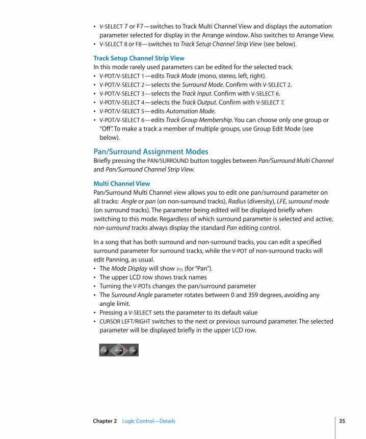
In a song that has both surround and non-surround tracks, you can edit a specified surround parameter for surround tracks, while the V-POT of non-surround tracks will edit Panning, as usual.• The Mode Display will show Pn (for “Pan”).• The upper LCD row shows track names• Turning the V-POTs changes the pan/surround parameter• The Surround Angle parameter rotates between 0 and 359 degrees, avoiding any
angle limit.• Pressing a V-SELECT sets the parameter to its default value• CURSOR LEFT/RIGHT switches to the next or previous surround parameter. The selected
parameter will be displayed briefly in the upper LCD row.
Chapter 2 Logic Control—Details 35

36
Channel Strip ViewPan/Surround Channel Strip View allows you to edit all surround parameters for the selected track.• The Mode Display will show Pn. (for “Pan/Surround channel strip”).• The upper LCD row shows the name of the track and “Pan/Surround”.
• V-POT/V-SELECT 1—edits angle (or pan on non-surround tracks)• V-POT/V-SELECT 2—edits diversity • V-POT/V-SELECT 3—edits LFE level • V-POT 4—selects the surround mode. Confirm with V-SELECT 4.• V-POT/V-SELECT 5—edits Surround X• V-POT/V-SELECT 6—edits Surround Y
The Angle/Diversity and X/Y pairs influence each other. Only the Angle/Diversity parameters are automated and recorded.
Alternate Mode OptionsHolding down the PAN/SURROUND button accesses a further sub-menu in the LCD:
• V-SELECT 1 or F1—switches to Pan/Surround Multi Channel View and selects angle• V-SELECT 2 or F2—switches to Pan/Surround Multi Channel View and selects diversity• V-SELECT 3 or F3—switches to Pan/Surround Multi Channel View and selects LFE level• V-SELECT 4 or F4—switches to Pan/Surround Multi Channel View and selects surround
mode• V-SELECT 6 or F5—switches to Pan/Surround Channel Strip View• V-SELECT 7 or F6—switches to Surround Angle/Diversity Multi Channel View:
• the Mode Display will show Ad (for “Angle/Diversity”)• the upper LCD row shows track names• the lower LCD row shows the surround angle currently assigned to each track• turning a V-POT changes the surround angle (or adjusts pan position on non-
surround tracks)• pressing a V-SELECT sets the surround angle to its default• the faders edit surround diversity
• V-SELECT 8 or F7—switches to Surround X/Y Multi Channel View:• the Mode Display will show XY (for “X/Y”–the X character is not available on a 7
segment display)• the upper LCD row shows track names• the lower LCD row shows the surround X value currently assigned to each track
Track 1 "Audio 1" Pan/SurroundSrrAng SrrDvr SrrLFE Mode
Angle Radius LFE Mode CStrip Ang/Dv
Chapter 2 Logic Control—Details

•
turning a
V-POT
changes the
surround X
value
(
or adjusts
pan position
on non-surround tracks)
•
pressing a
V-SELECT
sets
surround X
to its default
•
the faders edit surround
surround Y
Notes on Surround X/Y editing
X and Y have the value range
−
1000 to
+
1000, however the resolution is not that high, as surround positions are currently recorded in 7 bit only.
Note that X and Y act in a rectangular coordinate system. So value pairs outside the surround circle are not possible.When trying to set a value which would lead to an invalid position, the other coordinate is automatically adjusted to a valid position, e.g. moving Y to
+
1000 will lead X to become 0.
When editing only one coordinate, the other coordinate of the most recently track is memorized. This helps getting straight movement lines.
EQ Assignment Modes
Briefly pressing the
EQ
button toggles between
EQ Multi Channel View
or
EQ Channel Strip View
.
Multi Channel View
EQ Multi Channel View allows you to edit one equalizer parameter for all tracks:
Frequency
,
Gain
,
Q
or
EQ bypass
. The EQ “band” number, and parameter being edited will be displayed for one second when switching to this mode.
•
The
Mode Display
will show
E1 to E8, dependent on the selected EQ band number.• The upper LCD row shows track names• Turning the V-POTs changes the EQ parameter• Pressing a V-SELECT sets the parameter to its default value• CURSOR UP/DOWN switches to the next or previous EQ band.• CURSOR LEFT/RIGHT switches to the next or previous EQ parameter. The selected
parameter will be displayed briefly in the upper LCD row.
• Pressing a MUTE button while the SHIFT button is held down toggles the current EQ band’s Bypass status.
• When Flip Mode is enabled, the MUTE buttons display and edit the current EQ band’s Bypass status.
Chapter 2 Logic Control—Details 37

38
Channel Strip ViewEQ Channel Strip view allows you to edit all EQ parameters—in all bands—for the selected track.• The Mode Display will show EQ. (for “EQ channel strip”).• The upper LCD row shows the name of the track, “EQs”, the page number and total
number of pages—e. g. “Page 1/2”.• V-POT/V-SELECT 1—edits the Frequency of odd-numbered EQs• V-POT/V-SELECT 2—edits Gain of odd-numbered EQs• V-POT/V-SELECT 3—edits Q of odd-numbered EQs• V-POT/V-SELECT 4—edits Bypass of odd-numbered EQs• V-POT/V-SELECT 5—edits the Frequency of equally-numbered EQs• V-POT/V-SELECT 6—edits Gain of equally-numbered EQs• V-POT/V-SELECT 7—edits Q of equally-numbered EQs• V-POT/V-SELECT 8—edits Bypass of equally-numbered EQs• CURSOR LEFT/RIGHT switches to the next or previous EQ band. The number of EQ
bands displayed on the LCD depends on the number of Logic Control (XT) units (two EQ “bands” per unit) available.
Alternate Mode OptionsHolding down the EQ button accesses a further sub-menu in the LCD:• The Mode Display shows E_ or E_., dependent on whether you were in EQ Multi
Channel or EQ Channel Strip view• V-SELECT 1 or F1—switches to EQ Multi Channel View and selects Frequency• V-SELECT 2 or F2—switches to EQ Multi Channel View and selects Gain• V-SELECT 3 or F3—switches to EQ Multi Channel View and selects Q• V-SELECT 4 or F4—switches to EQ Multi Channel View and selects Bypass• V-SELECT 6 or F6—switches to EQ Channel Strip View• V-SELECT 7 or F7—switches to Frequency/Gain Multi Channel View. In this mode you
can edit the Frequency and Gain parameters of a specific EQ band (1 to 8) for all tracks.• the Mode Display will show F1 to F8, depending on the selected EQ band• the upper LCD row shows track names• the lower LCD row shows the Frequency of the selected EQ• turning a V-POT changes EQ Frequency• pressing a V-SELECT sets the EQ Frequency to its default value• use the MUTE buttons to Bypass the EQ• use the faders adjust the EQ Gain
• V-SELECT 8 or F8—switches to Frequency/Gain Channel Strip View. In this mode you can edit the Frequency and Gain parameters for all EQ bands of the selected track. Each pair of channel strips corresponds to one of the EQ bands.
Chapter 2 Logic Control—Details

• the Mode Display will show FG.• V-POTs 1 to 8 control EQ band 1 to 8 Frequency• MUTE buttons 1 to 8 control EQ band 1 to 8 Bypass• FADERs 1 to 8 control EQ band 1 to 8 Gain
Note that in this mode, the faders form a frequency response curve, if the EQ bands have ascending frequency values.
You can edit another track’s EQs by simply selecting the track, without leaving this view mode.
Send Assignment ModesBriefly pressing the SEND button toggles between Send Multi Channel or Send Channel Strip View.
Multi Channel ViewSend Multi Channel view allows you to edit one Send parameter for all tracks: Destination, Level, Position and Mute. The Send “slot” number, and parameter being edited will be displayed for one second when switching to this mode.• The Mode Display will show S1 to S8, depending on the selected Send “slot”.• The upper LCD row shows track names• Turning the V-POTs changes the Send parameter• Pressing a V-SELECT confirms the pre-selected Send Destination and set the other send
parameters to their default.• CURSOR UP/DOWN switches to the next or previous Send “slot”.• CURSOR LEFT/RIGHT switches to the next or previous Send parameter. The selected
parameter will be displayed briefly in the upper LCD row.
• Pressing a MUTE button while the SHIFT button is held down toggles the current Send’s Mute status.
• When Flip Mode is enabled, the MUTE buttons display and edit the current Send’s Mute status.
Tip: Ensure that the ZOOM button isn’t active when using the CURSOR keys.
Chapter 2 Logic Control—Details 39

40
Channel Strip ViewSend Channel Strip view allows you to edit all Send parameters for the selected track.• The Mode Display will show SE. (for “Send channel strip”).• The upper LCD row shows the name of the track, “Sends”, the page number and total
number of pages—e. g. “Page 1/4”
• V-POT/V-SELECT 1—edits Destination of odd-numbered Sends• V-POT/V-SELECT 2—edits Level of odd-numbered Sends• V-POT/V-SELECT 3—edits Position (pre/post) of odd-numbered Sends• V-POT/V-SELECT 4—edits Mute of odd-numbered Sends• V-POT/V-SELECT 5—edits Destination of even-numbered Sends• V-POT/V-SELECT 6—edits Level of even-numbered Sends• V-POT/V-SELECT 7—edits Position (pre/post) of even-numbered Sends• V-POT/V-SELECT 8—edits Mute of even-numbered Sends• With the horizontal Cursor buttons you shift pages. The number of Sends which are
displayed simultaneously depends on the number of Logic Control XTs you have.
Alternate Edit Mode OptionsHolding down the SEND button accesses a further sub-menu in the LCD:• The Mode Display shows S_ or S_., depending on whether you were in Send Multi
Channel or Send Channel Strip View
• V-SELECT 1 or F1—switches to Send Multi Channel View and selects Destination• V-SELECT 2 or F2—switches to Send Multi Channel View and selects Send Level• V-SELECT 3 or F3—switches to Send Multi Channel View and selects Position• V-SELECT 4 or F4—switches to Send Multi Channel View and selects Mute• V-SELECT 5 or F5—switches to Send Channel Strip View• V-SELECT 6 or F6—switches to Send Channel Strip 2 View:
This mode is similar to Send Channel Strip View, however the parameters are arranged in a different way. You can control one parameter of all Send “slots” for the selected track.
• The Mode Display will show SE. (for “Send channel strip”).
Track 1 "Audio 1" Sends Page 1/2Snd3Ds Send 3 Snd3Ps Snd3Mt Snd4Ds Send 4 Snd4Ps Snd4Mt
Dest Pos Level Mute CStrip CSt2 Ds/LvM Ds/LvC
Chapter 2 Logic Control—Details

•
The upper LCD row shows the name of the track, “Sends”, the page number and total number of pages—e.
g. “Page 1/4”
•
V-POT/V-SELECT 1
to
8
—edits the displayed parameter
•
With the horizontal Cursor buttons you shift pages. The number of parameters which are displayed simultaneously depends on the number of Logic Control XTs you have.
•
V-SELECT 7
or
F7
—switches to
Destination/Level Multi Channel View
:In this mode you can control one
Send
“slot” for all tracks. Each channel strip corresponds to the track shown in the upper LCD row.
•
the
Mode Display
will show
d1
to
d8
, depending on the selected
Send
•
the upper LCD row shows track names
•
the lower LCD row shows the destination of the selected
Send
•
turning a
V-POT
pre-selects the
Send Destination
•
pressing a
V-SELECT
confirms the pre-selected
Send Destination
•
the
SOLO buttons edit Send Position—SOLO LED on means “Pre Fader”• the MUTE buttons edit Send Mute• the faders edit Send Level
• V-SELECT 8 or F8—switches to Destination/Level Channel Strip View:In this mode you can control all Send slots for the selected track. Each channel strip corresponds to the Send number embossed below the LCD.
• the Mode Display will show dL.• turning a V-POT pre-selects the corresponding Send Destination• pressing a V-SELECT confirms a preselected Send Destination• the SOLO buttons edit Send Position—SOLO LED on means “Pre Fader”• the MUTE buttons edit Send Mute• the faders edit Send Gain
If one or more Sends are activated on multiple channels, you can switch between them in the Channel Strip Views by simply pressing the SELECT button for the desired channel.
Track 1 "Audio 1" Sends Page 1/2Snd1Ds Snd2Ds Snd3Ds Snd4Ds Snd5Ds Snd6Ds Snd7Ds Snd7Ds
Chapter 2 Logic Control—Details 41
42
Plug-In Assignment Modes
Pressing
PLUG-IN
toggles between
Plug-in Multi Channel
or
Plug-in Channel Strip View
.
Please note that there is one exception to this behavior: if you are in
Instrument Edit View , pressing this button switches to Plug-in Edit View .
Multi Channel View
This mode shows the plug-ins associated with a particular
Insert
“slot” for all channels.
•
The
Mode Display
will show
P1
to
P9
, or simply 10 to 16, dependent upon the selected Plug-In
Insert
“slot” number. Note that if an Audio Instrument channel is selected, the display will show
P1 to P9 and 10 to 15.• The upper LCD row shows track names.• The lower LCD row shows the currently selected plug-in for this insert slot. Muted
plug-ins are shown with an asterisk * which precedes the plug-in name.• Turning the V-POTs pre-selects a new plug-in. Until confirmed with the V-SELECT, the
plug-in name flashes.• Turning another V-POT will cancel any previous pre-selection and will start pre-
selection on the newly selected track.• Pressing a V-SELECT:
• confirms/activates the pre-selected plug-in (assuming that you’ve made your pre-selection by turning the V-POT)
• opens a plug-in editor window, if none are opened. If a plug in window is opened, and link mode is enabled, the selection of another plug-in will replace the existing plug-in shown.
• switches to Plug-in Edit View
To remove a plug-in, pre-select the value of “--” (by turning the V-POT all the way counterclockwise), and press the V-SELECT linked to the appropriate Insert slot. Logic Control will not switch to Plug-In Edit view, and no Plug-In window will be launched. If one was previously opened, it will be closed (if the “chain” icon is inactive).• The CURSOR UP/DOWN buttons change the currently displayed Plug-in Insert slot (1 to
8).• Pressing a V-SELECT while the SHIFT button is held down will mute/unmute the plug-
in.
• Pressing a MUTE button while the SHIFT button is held down toggles the will mute/unmute the plug-in.
Chapter 2 Logic Control—Details

Channel Strip ViewThis mode shows the plug-ins associated with all Insert “slots” for the selected channel.• The Mode Display will show PL.• The upper LCD row shows Ins1Pl through Ins8Pl• The lower LCD row shows the plug-in which is currently selected for this insert slot.
Muted plug-ins are indicated by an asterisk *, which precedes the plug-in name.• Turning the V-POTs pre-selects a new plug-in. Until activated, the plug-in name
flashes.• Turning another V-POT will cancel any previous pre-selection and will start pre-
selection on the newly selected track.• Pressing a V-SELECT:
• activates the pre-selected plug-in (assuming that you’ve made your pre-selection by turning the V-POT)
• opens a plug-in editor window if none are opened (if a plug in window is opened, and link mode is enabled, the selection of another plug-in will replace the existing plug-in)
• switches to Plug-in Edit View
To remove a plug-in, pre-select the value of “--” (by turning the V-POT all the way counterclockwise), and press the V-SELECT linked to the appropriate Insert slot. Logic Control will not switch to Plug-In Edit view, and no Plug-In window will be launched. If one was previously opened, it will be closed (if the “chain” icon is inactive).• Pressing a V-SELECT while the OPTION button is held down will mute/unmute the
plug-in
Plug-in Edit View• The Mode Display will show P1. to P8., depending on the number of the selected
Plug-In Insert “slot”.• Dependent on the NAME/VALUE button, the LCD display will change in the following
ways between the two modes:• Name The upper LCD row shows the track’s name, insert number, plug-in name,
current parameter page and total number of parameter pages.The lower LCD row shows the name of the parameter which is edited via the V-POT below.
• Value The upper LCD row shows the name of the parameter which is edited via the V-POT below.
The lower LCD row shows the current value of the parameter edited with the V-POT. If there is sufficient onscreen space, the unit type will be added—e. g. Hz.
• Turning the V-POTs changes the parameter
Chapter 2 Logic Control—Details 43

44
• Pressing a V-SELECT sets the parameter to its default value, except where the parameter only has two values (on/off, for example). In this case, pressing the V-SELECT toggles between these values.
• The CURSOR LEFT/RIGHT buttons switch to the next or previous parameter page.
Note that when shifting by a “page”, this always “quantizes” to integer pages. As an example:• the plug-in has 19 parameters• Logic Control shows parameters 1 to 8• CURSOR RIGHT shifts to 9 to 16• CURSOR RIGHT shifts to 12 to 19• CURSOR LEFT shifts back to 9 to 16, not to 4 to 11
This way, you always revert to the page positions you expect to find, and are comfortable with.• To switch by a single parameter, rather than by “page”, hold down the C/ALT key
while pressing the CURSOR LEFT/RIGHT button.• The CURSOR UP/DOWN buttons change the currently displayed Plug-in insert slot (1 to
8)
N. B. If you have a Control Surface Group consisting of several physical units, the parameters are distributed across their displays. The number of parameters shown is dependent on the settings in the Preferences, as discussed in the Logic Reference Manual.
When exiting Plug-In Edit View, the Plug-In window will be closed (if the “chain” icon is inactive).
CompatibilityLogic Control can edit all plug-ins which have automatable parameters. The plug-in type (built-in, TDM, VST, DirectX) is irrelevant.
DirectX supports automatable parameters since version 8. However it is not sufficient to install this version—the DirectX plug-ins must also support the new functions.
Chapter 2 Logic Control—Details

Some plug-ins however don’t provide parameter names and/or values as text. In this case the parameters are enumerated as “Control #1”, “Control #2” etc., and the values are displayed as numbers between 0 and 1000.
Some VST plug-ins don’t allow to retrieve the value range; in this case the range 0 to 1000 is assumed. This is disturbing with switches, as they can’t be toggled with V-POTs nor with V-SELECTs. In this case hold down OPTION and turn the V-POT.
Please contact the plug-in’s manufacturer in order to get a version which supports the mentioned features.
Instrument Assignment ModesPressing the INSTRUMENT button switches to “Instrument Multi Channel” view.
Please note that when in Plug-In Edit view, pressing the INSTRUMENT button will switch to Instrument Edit View.
If you can’t see the Audio Instrument channels, use the BANK or CHANNEL buttons in the FADER BANKS zone, or switch to Global View by pressing the AUDIO INSTRUMENT button. (This assumes that you have created at least one or more Audio Instrument channels in the Environment Audio layer).
Multi Channel ViewThis mode shows the Instrument Insert “slot” (slot 1) for all channels. • The Mode Display will show In• The upper LCD row shows track names• The lower LCD row shows the currently selected Instrument. Muted Instrument
names are preceded by an asterisk *• Turning the V-POTs pre-selects a new Instrument. Until activated, the pre-selected
Instrument name flashes.• Turning another V-POT will cancel any previous pre-selection and will start pre-
selection on the newly selected track.• Pressing a V-SELECT:
• activates the pre-selected Instrument plug-in (assuming that you’ve made your pre-selection by turning the V-POT)
• opens a plug-in editor window, if none are opened. If a plug in window is opened, and link mode is enabled, the selection of another Instrument plug-in will replace the existing one.
• switches to Instrument Edit View
To remove an instrument plug-in, pre-select the value of “--” (by turning the V-POT all the way counterclockwise), and press the V-SELECT. Logic Control will not switch to Instrument Edit view, and no Plug-In window will be launched. If one was previously opened, it will be closed (if the “chain” icon is inactive).
Chapter 2 Logic Control—Details 45

46
• Pressing a V-SELECT while the SHIFT button is held down mute/unmutes the Instrument
• Pressing a MUTE button while the SHIFT button is held down mute/unmutes the Instrument
Instrument Edit View• The Mode Display will show In.• Dependent on the NAME/VALUE button, the LCD changes in the following ways:
• Name—The upper LCD row shows the track’s name, instrument name, current parameter page and total number of parameter pages. The lower LCD row shows the name of the parameter edited with the V-POT below it.
• Value—The upper LCD row shows the name of the parameter edited with the V-POT below it. The lower LCD row shows the current value of the parameter edited with the V-POT. If there is sufficient space left, the unit is appended.
• Turning the V-POTs changes the corresponding parameter• Pressing a V-SELECT sets the parameter to its default value, except where the
parameter only has two values (on/off, for example). In this case, pressing the V-SELECT toggles between these values.
CompatibilityThe comments in section Compatibility section on page 44 also apply to software instruments.
Fader Bank ZoneThis area of the Logic Control surface contains six buttons.
Bank Left/RightMoves up or down by “banks” of channels/tracks. To quickly explain, a single Logic Control is only capable of viewing 8 tracks at a time in either Global or Mixer View. To see, and edit or mix more tracks, simply press the RIGHT/LEFT BANK buttons to switch between tracks 1—8, 9—16, 17—24 a. s. o.
The BANK button pair shifts the view section by the number of channels in the Control Surface Group. E. g. if you have a Logic Control and two Logic Control XT units, the view shifts by 24 channels.
Chapter 2 Logic Control—Details

Note that when shifting by bank, this always “quantizes” to integer banks. As an example:• your song has 19 tracks.• Logic Control shows tracks 1 to 8• BANK Right shifts to 9 to 16• BANK Right shifts to 12 to 19• BANK Left shifts back to 9 to 16, not to 4 to 11
This way, you always revert to the bank positions you expect, and are used to.
Channel Left/RightAs per the BANK buttons, but moves up or down in increments of a single channel.
Notes on Fader Bank EditingWhen holding down the OPTION button, pressing the BANK LEFT or CHANNEL LEFT button jumps to the first tracks, and pressing the BANK RIGHT or CHANNEL RIGHT button jumps to the last tracks in the song—as an example in a 64 track song, tracks 1 to 8 or tracks 57—64.
The Fader bank offset is memorized separately for Global views where one track type is displayed (MIDI, Inputs, Audio Tracks, Instruments, Aux, Busses, Outputs+Master), and there is also a separate fader bank offset for combination of multiple track types. This feature allows you e.g. to scroll to audio tracks 2 to 9 in Global Audio Track view and to scroll to instruments 5 to 12 in Global Instruments view. You can switch between the views without losing the fader bank offset.
FlipThe FLIP button enables/disables the following “flip”, “swap” or “zero” modes:• If the LED beside the FLIP button is off, flip/swap mode is off. The faders control
volume.• Pressing the FLIP button enables “flip mode” (the LED goes on): in this mode, the
current assignment of the eight V-POTs are mirrored on the eight channel faders. Pressing the FLIP button again disables flip mode.
Turning a V-POT in this mode will also move the corresponding fader.• Pressing the FLIP button while the SHIFT button is held down enables “swap mode”
(the LED will flash): in this mode, the encoder assignments are swapped with the fader assignments. Pressing SHIFT + FLIP again disables swap mode. As the LCD’s lower row shows the current value of the encoders, it will show volumes in this mode.
• Pressing FLIP without SHIFT held reverts to flip mode.
Chapter 2 Logic Control—Details 47

48
• Pressing CONTROL + FLIP switches to zero mode. Pressing CONTROL + FLIP again disables zero mode. In this mode the faders are set to zero and don’t move. Useful for acoustic/microphone recordings if Logic Control is located in the recording booth, and you don’t want to hear/capture any motor noise.
Both flip and swap mode work in all view modes.
Flip mode has the following advantages:• you can edit any type of parameter with a fader, rather than a V-POT, which allows
more accurate edits• you can edit with touch-sensitive faders. The V-POTs are not touch-sensitive, and thus
don’t allow existing (controller automation) movements to be overwritten by a constant value.
Global ViewThis button is discussed in Global View section, from page 18 onwards.
Master FaderControls the level of the Master fader in Logic’s Mixer. This reduces the level of all tracks, but does not affect their relative positions.
When there is no Master Volume object in the song (or in Logic Express where this object is not supported), Logic Control’s Master fader maps to Output 1-2.
To set the automation mode of the Master output, you need to select this object. To do so, press the OUTPUTS button and select the master output with the corresponding SELECT button.
If you use multiple audio systems simultaneously, the MASTER fader controls only the first audio system’s Master Volume (in the order as seen in the Audio Preferences window).
Chapter 2 Logic Control—Details

Display ZoneThese buttons affect what you see in the LCD and Position/Time Display.
Name/ValueTo toggle between the two Display formats—Name or Value—repeatedly press the NAME/VALUE button in the Display section of the Logic Control—just below the SMPTE/BEATS LEDs. For more information, see the Liquid Crystal Display (LCD) section, from page 21 onwards.
Pressing the NAME/VALUE button, while holding the SHIFT button, cycles through these three level meter modes:• Vertical—In this mode, the sixth (last) character of each channel in both LCD rows is
overlaid by a vertical level meter bar. When the level meter is not visible, the text character reappears. We chose the last, rather than the first, character for the level meter, as this character is blank in many cases, so no valuable information is “blocked out” by the level meter.
Tip: if it disturbs you that the D letter of the dB unit flickers when levels are displayed, you should switch off display if units. See the Logic Reference Manual.• Horizontal—with Peak Hold. In this mode, the second row is replaced by horizontal
level meter bars. Peak Hold is shown as a hollow box which disappears after 3 seconds. Overload (clipping) is displayed as an asterisk. It remains on the LCD until cleared (see below).
• Off—In this mode, no level meters are displayed in the LCD.
In all three modes, the SIGNAL LEDs function as per usual, indicating the presence of a signal.
N. B. The MIDI bandwidth required for the display of level meters is the same in all three modes—and is very low. The Position/Time Display updates require much more MIDI bandwidth than the level meters.
Pressing the NAME/VALUE button, while holding the CONTROL button, clears Overload (clipping) in both Logic’s Environment/Track Mixer, and the horizontal level meters on the Logic Control.
Pressing the NAME/VALUE button, while holding the CMD/ALT button, enters “Control Surface Group Settings Mode”. Here you can edit several control surface group settings, some of which are not accessible with a single button:
Chapter 2 Logic Control—Details 49

50
• V-POT/V-SELECT 5 (label “TrkNam”)—sets track name display format“Name”—track name only“#:Name”—track number and nameThis parameter can also be toggled with OPTION+NAME/VALUE
• V-POT/V-SELECT 6 (label “Lock”)—toggles Channel Strip View track lock“Off”—as you are used to: selecting a track also switches the currently edited Channel Strip track“On”—the currently edited Channel Strip Track is not affected by selecting a track.
When you switch from On to Off, this also updates the Channel Strip track
To edit another track in Locked mode, first disable Lock, then select the desired track, then re-enable Lock• V-POT/V-SELECT 7 (label “Disply”)—toggles LCD display format
“Name”—upper line displays global info, lower line displays parameter names“Value”—upper line displays parameter names, lower line displays parameter valuesThis parameter can also be toggled with NAME/VALUE.
• V-POT/V-SELECT 8 (label “Clock”)—toggles Clock display format“Beats”—clock is displayed in format bars/measures/beats/ticks“SMPTE”—clock is displayed in SMPTE formatThis parameter can also be toggled with SMPTE/BEATS.
Control Surface Group Settings Mode can be left by pressing NAME/VALUE, or by entering one of the Marker or Nudge modes.
SMPTE/BeatsTo toggle between the two Time formats, repeatedly press the SMPTE/BEATS button in the Display section at the top of the Logic Control—just below the SMPTE/BEATS LEDs. For more information, see the Song Position/SMPTE Time Display section on page 23.
Chapter 2 Logic Control—Details

The Function Key Zone
The eight Function Keys—F1 to F8—are assigned as follows:• F1 to F7 recalls screensets 1 to 7• F8 closes the top-most window, with “floating” windows closed first.
With the SHIFT key held down, the Function keys toggle particular windows:• F1—Arrangement• F2—Track Mixer• F3—Event Editor• F4—Score• F5—Hyper Editor• F6—Matrix Editor• F7—Transport• F8—Audio
With the CMD/ALT key held down, the Function keys trigger common key commands:• F1—Cut• F2—Copy• F3—Paste• F4—Clear• F5—Select All• F6—Select All Following• F7—Select Similar Objects• F8—Select Inside Locators
In some other “modes”, the Function keys perform other duties, such as shortcuts to Markers. Please see the Marker section on page 56. Also see the table towards the back of this manual.
Chapter 2 Logic Control—Details 51

52
The Global View ZoneThe Global View mode is activated by pressing any of the GLOBAL VIEW buttons. When any is activated, the green LED to the right of the GLOBAL VIEW button will illuminate.
Pressing multiple GLOBAL VIEW buttons simultaneously will display the objects of the selected types. To do so:
Hold down any GLOBAL VIEW button, and add or remove other object types by repeatedly pressing the other desired GLOBAL VIEW buttons. The display order of the objects matches the order of these buttons on the front panel of the Logic Control.
As an example: to see the busses and the outputs, hold down BUSSES, and then press OUTPUTS.
Further information on Global View is found in the Global View section on page 18.
Function Button ZoneThere are three areas in this zone—Modifiers, Automation and Utilities.
Modifier ButtonsThe four buttons in this area are similar to those found on your Mac OS or Windows computer keyboard (however independent from them). Many of Logic’s functions behave differently when one or more “modifier” key(s) is pressed, in conjunction with another key or mouse click. This also applies to the Logic Control. All “modified” Logic Control commands are covered in each function’s description.
A generic, and brief, description of each button follows:• SHIFT—an alternate function/meaning for a button• OPTION—the function applies to all objects. For relative value changes: the value is
set to the minimum or maximum, depending on whether you increase/decrease it.
Chapter 2 Logic Control—Details

• CONTROL—while held down, the Group Clutch is engaged, i.e. Track Groups are temporarily disabled.
• C/ALT—fine tuning variation of the function.
Automation Buttons
The five buttons in this area activate/deactivate the various automation modes of Logic. These work in conjunction with the channel SELECT switches. Simply choose the channel you wish to automate, select the Automation mode via one of these six buttons, and move the corresponding fader. The modes are outlined below:
• READ/OFF—Pressing this button repeatedly toggles between the “Read” and “Off” automation modes.• Off—Automation is off. The fader will neither send nor receive automation data.
Existing automation data remains untouched. It will still behave as a fader, however, and will adjust the volume or pan position etc. as usual.
• Read—The fader will read (follow) any existing automation data, but will not write data, regardless of any movements you make with the mouse or external control device.
• TOUCH—Writes new parameter changes when the fader is “touched” or V-POT turned during playback. Any existing track automation data (of the current fader type) will be replaced by new movements as long as the control is active—i. e. the fader is being touched or V-POT is being turned.
• LATCH—Similar to Touch mode, but the control remains activated, even when the fader is no longer being “touched” or V-POT being turned. In other words, following the release of the fader, the current fader value will replace the existing automation data for as long as the sequencer is in playback mode. Press STOP to finish.
• WRITE—Overwrites all existing automation data, or creates new automation data. Only use it if you wish to destroy all existing automation data.
• TRIM—Not enabled in the release version of Logic 5. Please consult the readme files of updated versions.
Chapter 2 Logic Control—Details 53

54
When the OPTION key is held down, pressing one of the Automation buttons chooses the selected automation mode for all tracks. When an automation mode has been selected for all tracks, the button’s LED will illuminate whenever the OPTION key is held.
N. B.—This is slightly different for the “Off” automation mode, when holding down the OPTION button. While doing so, all automation “writing” buttons will be turned off, but this does not necessarily mean that all tracks are actually in Off mode—they could also be in different modes. To ensure that you have set all tracks to Off mode, press READ/OFF twice (its LED goes on, then off ), while holding down the OPTION key.
Group
Pressing the GROUP button enters Group Edit Mode:• GROUP button’s LED is on• The Assignment display shows the currently displayed group, e.g. “G1”.• The Time display shows the group name (10 last characters if name is longer than 10
characters)• The upper LCD line displays track names• The lower LCD line displays group parameters• Group parameters can be toggled with V-SELECTs• CURSOR UP/DOWN selects previous/next group• CURSOR LEFT/RIGHT shifts group parameter display• SELECT buttons display if a track is a member of the group. Pressing a SELECT button
toggles track membership of the group
With Group Edit Mode off, holding down GROUP and pressing one or more SELECT buttons allows you to create a new group.
Pressing the GROUP button, while the SHIFT button is held down, creates a new group, opens the Group window and enters Group Edit mode.
Pressing the GROUP button, while the TRACK button is held down, switches to Track Multi Channel View, displaying the Track Group parameter. It displays which group the instrument is a member of. Multiple group membership is displayed like in the Track Mixer window. Turning a V-POT changes group membership. Note that you can only select one group (or “Off”) here.
Chapter 2 Logic Control—Details

Utilities ButtonsSaveSaves the current Song file. When pressed, a file save dialog will open on your computer screen, waiting for you to enter a filename as per usual.
The Logic Control LCD will display There is a file select dialog on the screen and the Position/Time Display will show ALErt. All LEDs will go off.
Once the file save has been confirmed—in Logic—the Logic Control will return all controls to their status prior to invoking the Save command.
Once the song has been saved and given a name, you may freely use the SAVE button to save any subsequent changes. This will happen without the alert messages and file save dialog appearing onscreen.
As a general working tip, you should always save your autoload song under a different name as the first step in any project. If this practice is adhered to, you will be able to simply press the SAVE button on the Logic Control to incrementally save your work.
The SAVE LED illuminates as soon as any save-able change has been made in Logic.
Holding down the OPTION button while pressing SAVE opens the “Save As.” file select box.
UndoPressing the UNDO button undoes the last undoable editing step. As Logic 5.1 supports virtually unlimited multiple undo/redo, The green UNDO LED does not illuminate to indicate an undo-able step, but to indicate that Redo is available. This warns you that performing an undoable editing step would render all Redo steps unavailable.
Holding down the SHIFT button while pressing UNDO performs a “Redo”.
Holding down the OPTION button while pressing UNDO opens the Undo History window.
CancelIf an alert is open on-screen, it triggers the Cancel (or Abort) button. More information on alerts is found in About Alert Messages section on page 23. Pressing the CANCEL button when no alert is opened will launch the Toolbox at the current on-screen position of the mouse cursor. Alternately, it will perform any function currently assigned to the computer keyboard Esc key.
If no alert is open, and Logic Control currently displays the contents of a folder track, the CANCEL button lets you leave the folder.
Chapter 2 Logic Control—Details 55

56
With CANCEL you can also cancel a blinking pre-selection of a parameter value.
EnterIf an alert is open, the ENTER button triggers the default button. See About Alert Messages section on page 23 for more information.
If no alert is open, and the selected track is a folder track, the ENTER button enters this folder.
The Transport ZoneThis section of the Logic Control features twelve (12) buttons. All are equipped with a dedicated LED to indicate their current status.
It should be noted that these buttons can be used independently, or in conjunction with one another, to navigate and edit your songs.
The functionality of these buttons is as follows:
MarkerWith the help of the MARKER button you can jump to, create and delete markers.
Marker and Nudge Mode are mutually exclusive; activating one deactivates the other.
Small Marker ModeHitting the MARKER button reassigns the behavior of the FAST FWD and REWIND buttons. They let you jump to the next or previous marker.
Pressing the MARKER button again returns to the default behavior of the FAST FWD and REWIND (see Rewind section on page 62 and Fast Fwd section on page 62).
Small Marker Mode is useful if you want to jump to markers, but still use the V-POTs for other purposes.
Chapter 2 Logic Control—Details

Large Marker ModeWhen pressing the MARKER button while holding down SHIFT, the LCD will update to display three options, assigned to the first three V-SELECTs.
• V-SELECT 1 to 5—display the first 5 Markers by name. Pressing a V-SELECT sets the current song position to this Marker. When the current song position is inside a marker, the lower line displays INSIDE, and the V-POT LED ring is on.
• V-SELECT 6—Cr w/o—Creates a marker without rounding to the nearest bar.• V-SELECT 7—Create—Creates a marker rounded to the nearest bar.• V-SELECT 8—Delete—Deletes the marker above the current SPL location.
To create or delete a marker at the current song position, simply press the appropriate V-SELECT switch.
The creation or deletion of markers is best used in conjunction with the JOG/SCRUB WHEEL. Simply move to the desired song position by dialing with the wheel, and then press the appropriate V-POT. • For coarse placement, simply use the wheel to move the SPL. • For fine placement, press the SCRUB button, and then use the wheel to place the SPL.
(Only appropriate if creating or deleting an un-rounded marker).
More information on the JOG/SCRUB WHEEL is found in The Jog/Scrub Wheel Zone section on page 65.
Large Marker Mode is terminated by pressing MARKER.
Temporary Marker ModeIf you want to enter Marker Mode temporarily (to quickly perform a few marker functions), hold down the MARKER button and press one or more of the above V-SELECTs: this will execute the marker function and leave marker mode as soon as you release the MARKER button.• When in this mode—with the MARKER button held—pressing the Function keys F1—
F8 “jumps” to the first 8 markers. As an example, to go to marker 3, press-hold MARKER and press F3.
• To jump between markers, with (or without) the MARKER button held, simply press the REWIND or FAST FWD buttons.
Chapter 2 Logic Control—Details 57

58
NudgeWith the help of the NUDGE button, you can nudge selected regions, sequences and events.
Marker and Nudge Mode are mutually exclusive; activating one deactivates the other.
Small Nudge ModeHitting the NUDGE button reassigns the behavior of the FAST FWD and REWIND buttons. They nudge the selected regions, sequences or events by the value defined in the Large Nudge Mode (see below).
Pressing the NUDGE button again returns to the default behavior of the FAST FWD and REWIND (see Rewind section on page 62 and Fast Fwd section on page 62).
Small Nudge Mode is useful if you want to nudge objects, but still use the V-POTs for other purposes.
Large Nudge ModeWhen pressing the NUDGE button while holding down SHIFT, the LCD will update to display eight options, assigned to the V-POTs and V-SELECTs. All these functions allow you to move the selected objects (audio region, MIDI sequence or events).
As an indicator, the position of the first selected region, sequence or event is displayed above V-POTs 3 and 4. If nothing is displayed, either a window is active which does not allow to select regions, sequences or events, or none are selected.
The functions are as per the following:• V-POT 1—Nudge—selects the nudge value used by the REWIND and F.FWD buttons.
These buttons move the selected object(s) backwards/forwards by the defined value.• V-SELECT 2—Pickup—moves to the current song position line location.• V-POT 3—Bar— moves by 1 bar.• V-POT 4—Beat—moves by the current song denominator value (beats).• V-POT 5—Format—moves by the current song format value (sub-divisions—1/16th
etc.).• V-POT 6—Ticks—moves by single ticks.• V-POT 7—Frames—moves by one SMPTE frame.• V-POT 8—Fram/2—moves by a half SMPTE frame.
Chapter 2 Logic Control—Details

• The cursor buttons always emulate the computer keyboard’s cursor keys. This allows you to easily select an object.
Large Nudge Mode is terminated by pressing NUDGE.
Temporary Nudge ModeIf you want to use NUDGE temporarily (for one or two “nudges”), hold down the NUDGE key, and user one or more of the above V-POTs: this will execute the nudge function and leave “nudge” mode as soon as you release the NUDGE button.
In Temporary Nudge Mode, the cursor buttons always emulate the computer keyboard’s cursor keys. This allows you to easily select an object.
The Nudge value for the REWIND and F.FWD buttons can also be defined with the function buttons:• F1—sets Ticks• F2—sets Format• F3—sets Beat• F4—sets Bar• F5—sets Frames• F6—sets Frames/2
CycleActivates/deactivates Cycle mode. By default, the cycle region will fall between the first two Markers.
Subsequent Markers can act as left/right boundaries for further cycle regions.
To “jump” between cycle regions—defined by the Markers:• Press the MARKER button, to activate it.• Press the CYCLE button, and when active, press the REWIND or FAST FWD buttons.
Quickly Define a Cycle LocatorTo set the left or right locator to the current song position, hold down CYCLE and press REWIND or FAST FWD. This also enables Cycle.
So the fastest way to define a new cycle region is:1 navigate to the left locator with the JOG/SCRUB WHEEL
2 press CYCLE + REWIND
3 navigate to the right locator with the JOG/SCRUB WHEEL
4 press CYCLE + FAST FWD
Chapter 2 Logic Control—Details 59

60
Cycle ViewPressing the SHIFT + CYCLE buttons activates Cycle View mode:• The Mode Display displays Cy• V-POT/V-SELECT 1—shows and edits the current Cycle status (off or on); you can also
use the CYCLE button• V-SELECT 2—BySel— sets the current Cycle region by the selection made in the
Arrange window—i. e. the selected regions or sequences• V-POT 3—Move— moves the current Cycle region by a bar with each “click” when
turning the V-POT• The display shows the left and right locators above V-POTs 5 and 7• Pressing V-SELECT 5 picks up the current song position for the left locator• Turning V-POT 5 changes the left locator in bars• Turning V-POT 6 changes the left locator in beats (denominator steps).• Pressing V-SELECT 7 picks up the current song position for the right locator• Turning V-POT 7 changes the right locator in bars• Turning V-POT 8 changes the right locator in beats (denominator steps)
To return to a regular Assignment mode, press one of the ASSIGNMENT buttons.
DropActivates/deactivates Drop-In mode.
To “jump” between drop-in regions:1 Press the MARKER button, to activate it.
2 Press the DROP button, and when active, press the REWIND or FAST FWD buttons.
Quickly Define a Drop LocatorTo set the Drop In or Drop Out locator to the current song position, hold down DROP and press REWIND or FAST FWD. This also enables Drop.
So the fastest way to define a new Drop region is:1 navigate to the Drop In locator with the JOG/SCRUB WHEEL
2 press DROP + REWIND
3 navigate to the Drop Out locator with the JOG/SCRUB WHEEL
4 press DROP + FAST FWD
Chapter 2 Logic Control—Details

Drop ViewPressing SHIFT + DROP buttons activates Drop View:• The Mode Display shows dr• V-POT/V-SELECT 1 shows and edits the current Drop status (off or on); you can also use
the DROP button• V-POT 3—Move— moves the current Drop region by a bar with each “click” when
turning the V-POT• The display shows the Drop In and Drop Out locators above V-POTs 5 and 7• Pressing V-SELECT 5 picks up the current song position for the Drop In locator• Turning V-POT 5 changes the Drop In locator in bars• Turning V-POT 6 changes the left locator in beats (denominator steps)• Pressing V-SELECT 7 picks up the current song position for the Drop Out locator• Turning V-POT 7 changes the Drop Out locator in bars• Turning V-POT 8 changes the right locator in beats (denominator steps)
Changing a drop locator with Logic Control enables Drop mode.
To return to a regular Assignment mode, press one of the ASSIGNMENT buttons.
ReplaceActivates/deactivates Replace mode.
ClickEnables/Disables MIDI (or computer) metronome click. There are independent click settings for play and record. The click settings are enabled or disabled, dependent on the current Record state (see the “MIDI/Monitor Metronome Click” key command)
Pressing SHIFT + CLICK buttons toggles both External Sync Mode and Transmit MMC.
SoloThe SOLO button behaves as per the Solo key command. Individual channels can be soloed via the channel SOLO switches on each channel strip. Subsequent objects (sequences or audio regions) can be selected and solo-ed along with the selected channels. Each channel features an independent SOLO LED which illuminates when a track is soloed. The RUDE SOLO LED—just to the right of the Position/Time Display—also illuminates whenever any track is soloed.
Pressing SHIFT + SOLO buttons enables the Solo Lock mode.
Chapter 2 Logic Control—Details 61
62
RewindRewinds/shuttles through the song. If pressed repeatedly while rewinding, the rewind speed will be accelerated with each button push. If the FAST FWD button is pressed while REWIND is engaged, the fast rewind will be slowed. Repeated presses of the FAST FWD button will slow down, stop, and eventually reverse the shuttle direction. Pressing the STOP button will halt the rewind. Using the JOG/SCRUB WHEEL will also exit shuttle mode.
When one of the Marker Modes is activated, repeated presses of the REWIND button will move the Song Position Line (SPL) to the previous marker.
When one of the Nudge Modes is activated, the REWIND button will move the selected object(s) backward by the value defined in Large Nudge Mode.
Fast FwdFast forwards/shuttles through the song. If pressed repeatedly while fast forwarding, the shuttle speed will be accelerated with each button push. If the REWIND button is pressed while FAST FWD is engaged, the fast forward will be slowed. Repeated presses of the REWIND button will slow down, stop, and eventually reverse the shuttle direction. Pressing the STOP button will halt the fast forward. Using the JOG/SCRUB WHEEL will also exit shuttle mode.
When one of the Marker Modes is activated, repeated presses of the FAST FWD button will move the Song Position Line to the next marker.
When one of the Nudge Modes is activated, the FAST FWD button will move the selected object(s) forward by the value defined in Large Nudge Mode.
As a tip, you can combine Markers with Cycle regions by pressing the respective buttons on the Logic Control. This, in conjunction with the “stepping” between markers mentioned above (using the REWIND and FAST FWD buttons) will move the SPL, and will automatically set a cycle region between adjacent markers. Try this, and other options, with various button combinations.
Chapter 2 Logic Control—Details

StopStops all other Transport functions. Pressing the STOP button a second time will return to the song start point, or the beginning of the nearest cycle region, if Cycle is active. Repeated presses will toggle between the two.
PlayPlays from the current song position. If pressed repeatedly, it will jump to the beginning of the nearest cycle region, if Cycle is active.
SHIFT + PLAY works as a Pause command.
RecordActivates recording on the selected MIDI, Audio or Audio Instrument track.
A special note for Audio tracks: When the first Audio track is armed by pressing the REC/RDY switch on the desired channel, a file save dialog will open on your computer screen, waiting for you to enter a filename as per usual. The Logic Control LCD will display There is a file select dialog on the screen and the Position/Time Display will show ALErt. All LEDs will go off.
Once the file name has been entered—in Logic—the Logic Control will return all controls to their status prior to invoking the REC/RDY command.
Once the “default” audio file name has been entered, you may freely select and “arm” any Audio track, and then press the RECORD button. This will happen without the alert messages and file save dialog appearing onscreen.
As a general working tip, you should also define a “default” audio file name, after saving your autoload song under a different name. These should be the first steps when creating any project.
Chapter 2 Logic Control—Details 63

64
The Cursor/Zoom Key ZoneThis collection of five buttons serves a number of purposes.
Normal operationWhen the ZOOM button’s LED is off, these buttons select the current parameter, shift the current parameter page or Send/EQ/Insert slot, depending on the current V-POT assignment.
When holding down the OPTION button, the CURSOR LEFT/RIGHT buttons scroll to the first/last page, and the CURSOR UP/DOWN buttons scroll to the first/last slot.
When holding down the C/ALT button, the CURSOR LEFT/RIGHT buttons shift the parameter display by only one parameter instead of by one page.
In View modes which don’t need the cursor keys to shift pages or slots, they emulate the computer keyboard’s cursor keys. Example: Track Multi Channel View.
In Large Nudge Mode and Temporary Nudge Mode, the cursor buttons always emulate the computer keyboard’s cursor keys. This allows you to easily select an object.
Zoom modePressing the ZOOM button enables Zoom mode. The CURSOR buttons can then be used to change the vertical or horizontal zoom factor of the active window.
In the Arrange window:
• OPTION and CURSOR UP/DOWN changes the zoom factor of the selected track.• OPTION and CURSOR LEFT resets the zoom factor of the selected track• OPTION and CURSOR RIGHT resets the zoom factor of all tracks which are of the same
class (audio, MIDI etc.) as the selected track.
Computer Cursor Key EmulationTo use the cursor buttons as a replacement for the computer keyboard cursor keys, hold down the SHIFT key.
By pressing SHIFT and ZOOM, the cursor keys go to Permanent Cursor Key Mode, i. e. they mimic the computer cursor keys without the need to hold down SHIFT. In this mode, the Zoom button LED flashes.
Chapter 2 Logic Control—Details

The Jog/Scrub Wheel ZoneThe JOG/SCRUB WHEEL and SCRUB button can be used to navigate through the song, which is useful for a number of Transport tasks. Simply turn the dial to use it. The following Scrub modes change the behavior of the JOG/SCRUB WHEEL.• SCRUB mode off: the JOG/SCRUB WHEEL moves the SPL• SCRUB mode on: the JOG/SCRUB WHEEL performs scrubbing. “Scrubbing” allows you to
hear the data of the selected track while scrolling/moving through the song.
Audio tracks are normally played back with 100% original speed. If you prefer 200%, choose menu item Audio > Audio Hardware & Drivers, open the DAE section and set Max. Scrub Speed to Double.
Note: You can also use the SCRUB button for Pause functionality.
• SHUTTLE mode (SCRUB button LED flashing): the JOG/SCRUB WHEEL shuttles the SPL, i.e. turning it increases or decreases the speed the SPL moves.
Functions and MenusChannel Strip (x8)Logic Control Modifier Function/Comments
V-POT — Modify parameter displayed in LCD.
OPTION Set parameter to minimum or maximum value.
C/ALT Modify parameter at high resolution.
V-SELECT — Set parameter displayed on LCD to default value, or: Switch between two possible values.
flashing pre-selection:
— Enter the pre-selected value.
menu options:
— Enter whatever option is visible in display.
If track is folder:
— Enter folder.
REC/RDY — Toggle Record Enable of track.
OPTION Disable Record Enable for all tracks.
SOLO — Toggle Solo of track.
OPTION Disable Solo for all tracks.
In Send Destination/Level Multi Channel View:
— Toggle pre/post status of selected send.
In Send Destination/Level Channel Strip View:
— Toggle pre/post of send on selected track.
Chapter 2 Logic Control—Details 65

66
MUTE — Toggle Mute of track.
OPTION Disable Mute for all tracks.
In Track Multi Channel View:
SHIFT Toggle Mute/Bypass of the shown parameter
In EQ Multi Channel View:
SHIFT Toggle Bypass of the current EQ band
In EQ Frequency/Gain View:
— Toggle bypass of selected EQ band.
In Send Multi Channel View:
SHIFT Toggle bypass of selected send.
In Send Destination/Level Multi Channel View:
— Toggle bypass of selected send.
In Send Destination/Level Channel Strip View:
— Toggle mute of send on selected track.
In Plug-in Multi Channel View:
SHIFT Toggle bypass of plug-in.
In Instrument Multi Channel View:
SHIFT Toggle bypass of instrument.
SELECT — Select track.
SHIFT Set track volume to unity level (0 dB).
OPTION create a new track with the same instrument of the selected track and switches to Arrange View
SHIFT+OPTION
create a new track with the next instrument of the selected track and switches to Arrange View
Logic Control Modifier Function/Comments
Chapter 2 Logic Control—Details
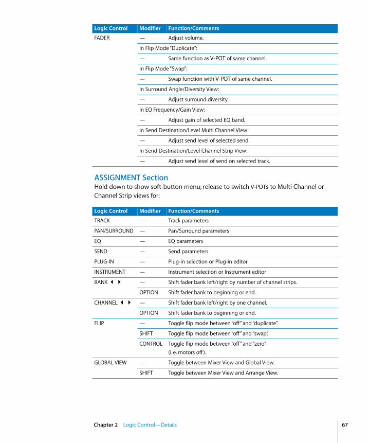
ASSIGNMENT SectionHold down to show soft-button menu; release to switch V-POTs to Multi Channel or Channel Strip views for:
FADER — Adjust volume.
In Flip Mode “Duplicate”:
— Same function as V-POT of same channel.
In Flip Mode “Swap”:
— Swap function with V-POT of same channel.
In Surround Angle/Diversity View:
— Adjust surround diversity.
In EQ Frequency/Gain View:
— Adjust gain of selected EQ band.
In Send Destination/Level Multi Channel View:
— Adjust send level of selected send.
In Send Destination/Level Channel Strip View:
— Adjust send level of send on selected track.
Logic Control Modifier Function/Comments
Logic Control Modifier Function/Comments
TRACK — Track parameters
PAN/SURROUND — Pan/Surround parameters
EQ — EQ parameters
SEND — Send parameters
PLUG-IN — Plug-in selection or Plug-in editor
INSTRUMENT — Instrument selection or Instrument editor
BANK 34 — Shift fader bank left/right by number of channel strips.
OPTION Shift fader bank to beginning or end.
CHANNEL 34 — Shift fader bank left/right by one channel.
OPTION Shift fader bank to beginning or end.
FLIP — Toggle flip mode between “off” and “duplicate”.
SHIFT Toggle flip mode between “off” and “swap”.
CONTROL Toggle flip mode between “off” and “zero” (i. e. motors off ).
GLOBAL VIEW — Toggle between Mixer View and Global View.
SHIFT Toggle between Mixer View and Arrange View.
Chapter 2 Logic Control—Details 67

68
DISPLAY Parameters
Function Buttons
Logic Control Modifier Function/Comments
NAME/VALUE — Toggle between parameter name and parameter value display.
SHIFT Cycle through level meter displays: vertical, horizontal and off.
OPTION Toggle between track name and track number:name display.
CONTROL Clear clip/overload flags.
CMD/ALT Enter “Control Surface Group Settings Mode”
SMPTE/BEATS — Toggle between SMPTE and Beat format in clock display.
Logic Control Modifier Function/Comments
FI — Recall screen set 1.
SHIFT Toggle Arrange window.
CMD/ALT Cut
TRACK Switch to Multi Channel View—Volume.
PAN/SURROUND
Switch to Multi Channel View—Pan/surround angle.
EQ Switch to Multi Channel View—Bypass.
SEND Switch to Multi Channel View—Destination.
MARKER Create Marker without rounding
NUDGE Nudge value: Tick
F2 — Recall screen set 2.
SHIFT Toggle Track Mixer window.
CMD/ALT Copy
TRACK Switch to Multi Channel View—Pan.
PAN/SURROUND
Switch to Multi Channel View—Pan/surround radius.
EQ Switch to Multi Channel View—EQ Type.
SEND Switch to Multi Channel View—Level.
MARKER Create Marker with rounding
NUDGE Nudge value: Format
Chapter 2 Logic Control—Details

F3 — Recall screen set 3.
SHIFT Toggle Event Editor window.
CMD/ALT Paste
TRACK Switch to Multi Channel View—Track Mode.
PAN/SURROUND
Switch to Multi Channel View—Pan/surround LFE.
EQ Switch to Multi Channel View—Frequency.
SEND Switch to Multi Channel View—Position.
MARKER Delete Marker
NUDGE Nudge value: Beat
F4 — Recall screen set 4.
SHIFT Toggle Score window.
CMD/ALT Clear
TRACK Switch to Multi Channel View—Input.
PAN/SURROUND
Switch to Multi Channel View—Pan/surround mode.
EQ Switch to Multi Channel View—Gain.
SEND Switch to Multi Channel View—Mute.
NUDGE Nudge value: Bar
F5 — Recall screen set 5.
SHIFT Toggle Hyper Edit window.
CMD/ALT Select All
TRACK Switch to Multi Channel View—Output.
PAN/SURROUND
Switch to Channel Strip View.
EQ Switch to Multi Channel View—Q Factor.
SEND Switch to Channel Strip View.
NUDGE Nudge value: Frame
F6 — Recall screen set 6.
SHIFT Toggle Matrix Editor window.
CMD/ALT Select All Following
TRACK Switch to Multi Channel View—Automation.
PAN/SURROUND
Switch to Angle/Diversity View.
EQ Switch to Channel Strip View.
SEND Switch to Channel Strip 2 View.
NUDGE Nudge value: 1/2 Frame
Logic Control Modifier Function/Comments
Chapter 2 Logic Control—Details 69
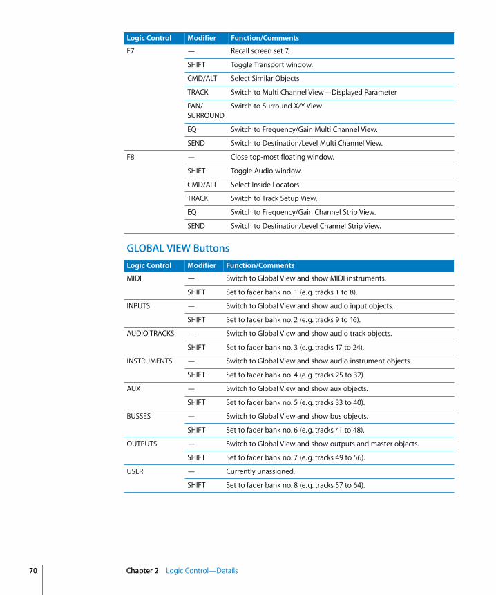
70
GLOBAL VIEW Buttons
F7 — Recall screen set 7.
SHIFT Toggle Transport window.
CMD/ALT Select Similar Objects
TRACK Switch to Multi Channel View—Displayed Parameter
PAN/SURROUND
Switch to Surround X/Y View
EQ Switch to Frequency/Gain Multi Channel View.
SEND Switch to Destination/Level Multi Channel View.
F8 — Close top-most floating window.
SHIFT Toggle Audio window.
CMD/ALT Select Inside Locators
TRACK Switch to Track Setup View.
EQ Switch to Frequency/Gain Channel Strip View.
SEND Switch to Destination/Level Channel Strip View.
Logic Control Modifier Function/Comments
Logic Control Modifier Function/Comments
MIDI — Switch to Global View and show MIDI instruments.
SHIFT Set to fader bank no. 1 (e. g. tracks 1 to 8).
INPUTS — Switch to Global View and show audio input objects.
SHIFT Set to fader bank no. 2 (e. g. tracks 9 to 16).
AUDIO TRACKS — Switch to Global View and show audio track objects.
SHIFT Set to fader bank no. 3 (e. g. tracks 17 to 24).
INSTRUMENTS — Switch to Global View and show audio instrument objects.
SHIFT Set to fader bank no. 4 (e. g. tracks 25 to 32).
AUX — Switch to Global View and show aux objects.
SHIFT Set to fader bank no. 5 (e. g. tracks 33 to 40).
BUSSES — Switch to Global View and show bus objects.
SHIFT Set to fader bank no. 6 (e. g. tracks 41 to 48).
OUTPUTS — Switch to Global View and show outputs and master objects.
SHIFT Set to fader bank no. 7 (e. g. tracks 49 to 56).
USER — Currently unassigned.
SHIFT Set to fader bank no. 8 (e. g. tracks 57 to 64).
Chapter 2 Logic Control—Details

MODIFIERS—While Held Down:
AUTOMATION Buttons
UTILITIES Buttons
SHIFT Switch to second function.
OPTION Apply function to all tracks or set parameter to minimum/maximum.
CONTROL Engage Group Clutch while held down
C/ALT Enable fine mode; shift parameter page by 1 parameter instead of page.
Logic Control Modifier Function/Comments
READ/OFF — Set selected track’s automation to Read or Off.
OPTION Set all tracks’ automation to Read or Off.
TOUCH — Set selected track’s automation to Touch.
OPTION Set all tracks’ automation to Touch.
LATCH — Set selected track’s automation to Latch.
OPTION Set all tracks’ automation to Latch.
WRITE — Set selected track’s automation to Write.
OPTION Set all tracks’ automation to Write.
TRIM Currently unassigned.
GROUP — Enter Group Edit Mode.
SHIFT Create a new group, open the Group window and enter Group Edit mode
TRACK Switch to Track Multi Channel View, displaying Track Group parameter
Logic Control Modifier Function/Comments
SAVE — Save Song.
OPTION Save Song as…
UNDO — Undo.
SHIFT Redo.
OPTION Open Undo History.
CANCEL — Leave folder.
Flashing pre-selection:
— Cancel pre-selection.
In alerts:
— Execute “Cancel” button.
ENTER — Enter folder of selected track.
In alerts:
— Execute default button.
Chapter 2 Logic Control—Details 71
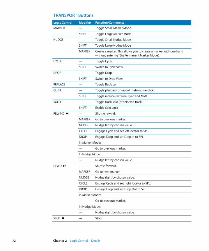
72
TRANSPORT ButtonsLogic Control Modifier Function/Comments
MARKER — Toggle Small Marker Mode.
SHIFT Toggle Large Marker Mode
NUDGE — Toggle Small Nudge Mode.
SHIFT Toggle Large Nudge Mode
MARKER Create a marker. This allows you to create a marker with one hand without entering “Big Permanent Marker Mode”.
CYCLE — Toggle Cycle.
SHIFT Switch to Cycle View.
DROP — Toggle Drop.
SHIFT Switch to Drop View.
REPLACE — Toggle Replace.
CLICK — Toggle playback or record metronome click.
SHIFT Toggle internal/external sync and MMC.
SOLO — Toggle track solo (of selected track).
SHIFT Enable Solo Lock
REWIND 7 — Shuttle rewind.
MARKER Go to previous marker.
NUDGE Nudge left by chosen value.
CYCLE Engage Cycle and set left locator to SPL.
DROP Engage Drop and set Drop In to SPL.
In Marker Mode:
— Go to previous marker.
In Nudge Mode:
— Nudge left by chosen value.
F.FWD 8 — Shuttle forward.
MARKER Go to next marker.
NUDGE Nudge right by chosen value.
CYCLE Engage Cycle and set right locator to SPL.
DROP Engage Drop and set Drop Out to SPL.
In Marker Mode:
— Go to previous marker.
In Nudge Mode:
— Nudge right by chosen value.
STOP < — Stop.
Chapter 2 Logic Control—Details

Cursor Keys & Scrub Wheel
PLAY 4 — Play.
SHIFT Pause.
RECORD = — Record.
Logic Control Modifier Function/Comments
Logic Control Modifier Function/Comments
CURSOR 34 If in Multi Channel View:
— Select previous/next parameter or of current View.
ZOOM Scroll window horizontally by page
If in Channel Strip EQ, Send View or Plug-in/Instrument Edit View:
— Shift current editor page by 1 page.
C/ALT Shift current editor page by 1 parameter.
ZOOM Scroll window horizontally by page
Otherwise (always in Nudge mode):
— Mimic computer keyboard cursor left/right keys.
ZOOM Scroll window horizontally by page
In Zoom mode:
— Change horizontal zoom level
SHIFT Reset individual track zoom of current track (Cursor left) or all tracks of same class (Cursor right)
CURSOR 56 In Channel Strip EQ-, Send View- or Plug-In/Instrument Editor View:
— Select previous/next EQ band, Send or insert slot.
ZOOM Scroll window vertically by page
Otherwise (always in Nudge mode):
— Mimic computer keyboard cursor up/down keys
ZOOM Scroll window vertically by page
In Zoom Mode:
— Change vertical zoom level
SHIFT Change individual track zoom of current track
ZOOM — Toggle between default cursor button behavior (see above) and Zoom mode
SHIFT Toggle between default cursor button behavior and permanently mimicking computer keyboard cursor keys
SCRUB — Toggle scrub mode
SHIFT enable Shuttle mode on the Jog Wheel (SCRUB button LED flashes)
Chapter 2 Logic Control—Details 73

74
External Inputs
JOG WHEEL — Move song position line.
CYCLE Set the Left Locator to the current SPL, advance the SPL as normally, then set the Right Locator to the SPL. Further Jog Wheel turns while still holding down CYCLE advances the SPL and sets the Right Locator again. Tip: rotating the jog wheel counterclockwise while holding down CYCLE defines a skip-cycle range.
DROP Set the Drop In Locator to the current SPL, advance the SPL as normally, then set the Drop Oout Locator to the SPL. Further Jog Wheel turns while still holding down DROP advances the SPL and sets the Drop out Locator again.
In Scrub Mode (SCRUB button LED on):
— Scrub
In Shuttle Mode (SCRUB button LED flashing):
— Shuttle
Logic Control Modifier Function/Comments
Logic Control Modifier Function
USER SWITCH A — Play/Stop
USER SWITCH B — Drop In/Out
EXTERNAL CONTROL
— Master Volume
Chapter 2 Logic Control—Details

3
3 Mackie C4You can use the C4 in an own control surface group (place its icon below Logic Control) or combined with a Logic Control/XT (place the icon right of the existing icons). In the latter case, the C4 adds 8 channels in Multi Channel views.
We recommend to use the C4 in an own control surface group. This allows you to edit instruments and plug-ins and independently do mixing on the Logic Control or other control surface.
V-POTs, V-SELECTsThe function depends on current view and optional overlay (see below).
The top row (row 1) consists of V-POT/V-SELECT 1 to 8.
Row 2 consists of V-POT/V-SELECT 9 to 16.
Row 3 consists of V-POT/V-SELECT 17 to 24.
The bottom row (row 4) consists of V-POT/V-SELECT 25 to 32.
V-POT/V-SELECT 1 to 8While no overlay is active, V-POT/V-SELECT 1 to 8 (i.e. the top row) normally do the same as on a Logic Control or Logic Control XT.
V-POT/V-SELECT 9 to 32These V-POTs have additional functionality in many views.
In Multi Channel views, the V-POT/V-SELECTs of row 2, 3, and 4 usually edit the parameter following the parameter edited on row 1.
Example: in Pan Multi Channel view, when row 1 edits Pan/Surround angle, row 2 edits Surround Diversity, row 3 edits LFE and row 4 edits Surround Mode
In Channel Strip view, all four rows build a group of 32 parameters which can be edited.
In Plug-in and Instrument edit views, it can be split up into two groups (8/24, 16/16 or 24/8 parameters), see below.
75

76
Pan/Surround Multi Channel View:Row 2 edits Pan/Surround parameter 2
Row 3 edits Pan/Surround parameter 3
Row 4 edits Pan/Surround parameter 4
(in the order Pan/Angle, Diversity, LFE, Surround Mode, X, Y)SINGLE left/right changes the parameter edited in row 1, and thus also affects the parameter edited in row 2 to 4
Surround Angle/Diversity View(to be entered on C4 with CHAN STRIP, V-SELECT 31)
Row 1 edits Surround Angle
Row 2 edits Surround Diversity
Surround X/Y View(only to be entered from Logic Control)
Row 1 edits Surround X
Row 2 edits Surround Y
Track Multi Channel ViewRow 1 edits Track parameter 4
Row 2 edits Track parameter 3
Row 3 edits Track parameter 2
Row 4 edits Track parameter 1, i.e. the parameter edited by V-POTs on a Logic Control or XT
(in the order Volume, Pan/Angle, Track Mode, Input, Output, Automation Mode, Group, Displayed Automation Parameter)
The row order is reversed, so that the lowest row editing parameter 1 is closest to the buttons
BANK left/right and SINGLE left/right change the parameter edited in row 4, and thus also affects the parameter edited in row 1 to 3
EQ Multi Channel ViewRow 1 edits EQ Band Bypass
Row 2 edits EQ Band Frequency
Row 3 edits EQ Band Gain
Chapter 3 Mackie C4

Row 4 edits EQ Band Q Factor
INSERT up/down selects the edited EQ band
EQ Channel Strip ViewRow 1 edits EQ Frequency of all 8 bands
Row 2 edits EQ Gain of all 8 bands
Row 3 edits EQ Q of all 8 bands
Row 4 edits EQ Bypass of all 8 bands
Send Multi Channel ViewRow 1 edits Send Destination
Row 2 edits Send Level
Row 3 edits Send Position
Row 4 edits Send Mute
INSERT UP/DOWN selects the edited Send slot
Send Channel Strip ViewRows 1 to 4 edit 32 Send parameters
SINGLE left/right shifts display of Send parameters
Send Channel Strip View 2Rows 1 to 4 edits 32 Send parameters
SINGLE left/right shifts display of Send parameters
Send Destination/Level ViewRow 1 edits Send Destination
Row 2 edits Send Level
Row 3 edits Send Position
Row 4 edits Send Mute
INSERT up/down selects the edited Send slot
Plug-in Select Multi Channel ViewINSERT up/down selects the edited plug-in insert
Plug-in Edit ViewV-POT/V-SELECT 1 to 32 build a group of 32 parameters. Split is possible.
Chapter 3 Mackie C4 77

78
INSERT up/down selects the edited plug-in insert
BANK left/right shifts the edited parameters by 32. In Split mode, this applies to Split Upper; when holding down SHIFT: applies to Split Lower
SINGLE left/right shifts the edited parameters by 1. In Split mode, this applies to Split Upper; when holding down SHIFT: applies to Split Lower
Instrument Edit ViewV-POT/V-SELECT 1 to 32 build a group of 32 parameters. Split is possible.
BANK left/right shifts the edited parameters by 32. In Split mode, this applies to Split Upper; when holding down SHIFT: applies to Split Lower
SINGLE left/right shifts the edited parameters by 1. In Split mode, this applies to Split Upper; when holding down SHIFT: applies to Split Lower
Buttons at BottomSPLITToggles edit split between 4/0, 1/3, 2/2 and 3/1 rows. Edit Split alllows you to edit two separate sections of a plug-in/instrument or even two different ones.
Split Edit is also possible across multiple C4 units. As an example with two units, pressing the SPLIT button gets you following split modes:• 1/7 (i.e. Split Upper is top line of first unit, Split Lower is bottom 3 lines of first unit
and all lines of second unit. LED 1/3 is lit),• 2/6 (i.e. Split Upper is top 2 lines of first unit, Split Lower is bottom 2 lines of first unit
and all lines of second unit. LED 2/1 is on),• 3/5 (LED 3/1 is on),• 4/4 (all 3 LEDs are on),• 5/3 (all 3 LEDs are on),• 6/2 (all 3 LEDs are on) and• 7/1 (all 3 LEDs are on).
LOCKToggles Track Lock. When enabled, selecting a track does not switch the currently selected track
SPOT ERASECurrently unassigned
MARKERToggles between Marker overlay (see below) and normal view
TRACKToggles between Track overlay (see below) and normal view
Chapter 3 Mackie C4

Alternate Mode OptionsHolding down the TRACK button accesses a further sub-menu in the bottom LCD to enter Global View with a certain object type:• V-SELECT 25 switches to MIDI tracks• V-SELECT 26 switches to Inputs• V-SELECT 27 switches to Audio tracks• V-SELECT 28 switches to Audio Instrument tracks• V-SELECT 29 switches to Auxiliary tracks• V-SELECT 30 switches to Busses• V-SELECT 31 switches to Outputs• V-SELECT 32 switches to Master output
Releasing the TRACK button without pressing a V-SELECT returns to Mixer View.
CHAN STRIPToggles between Channel Strip overlay (see below) and normal view.
Alternate Mode OptionsHolding down the CHAN STRIP button accesses a further sub-menu in the bottom LCD:• V-SELECT 25 switches to Pan/Surround Channel Strip• V-SELECT 26 switches to EQ Channel Strip• V-SELECT 27 switches to Send Channel Strip
FUNCTIONToggles between Function overlay (see below) and normal view.
Modifier ButtonsSHIFT: as with Logic Control, switches other buttons to alternate function, see “+ SHIFT”
OPTION: as with Logic Control, while held down, parameters are set to minimum/maximum when edited with V-POT
CTRL: as with Logic Control, engages the Group Clutch
CMD/ALT: as with Logic Control, while held down, parameters are edited in fine mode with V-POT
BANK left/rightShifts parameter display by one page in certain views (see above).
SINGLE left/rightShifts parameter display by one parameter in certain views (see above).
TRACK L/RShifts the currently edited track (in a Channel Strip view) to the previous or next track.
While SHIFT is held down: same, but for Split Lower.
Chapter 3 Mackie C4 79

80
SLOT UP/DOWNSelects the currently edited EQ, Send or plug-in insert (see above).
Marker OverlayWhile the MARKER button light is on, the Marker overlay is active.
A Logic Control in the same control surface group shows “MA” in the assignment display.
V-SELECT 1 to 30 goes to Marker 1 to 30. The upper LCD line shows the marker name; the lower line shows “INSIDE” when the song position is inside a marker.
V-SELECT 31 creates a new marker.
V-SELECT 32 deletes the current marker.
Track OverlayWhile the TRACK button light is on, the Track overlay is active.
A Logic Control in the same control surface group shows “tr” in the assignment display.
V-SELECT 1 to 32 changes currently edited track. When a track is selected for Split Upper, the lower LCD line shows “UPPER” for this track. For a track selected for Split Lower, “LOWER” is shown.
To select a track for Split Upper, press the appropriate V-SELECT.
To select a track for Split Lower, press the V-SELECT while holding down SHIFT. A Logic Control in the same control surface group shows “tL” in the assignment display.
BANK left/right shifts the fader bank by 32 tracks.
SINGLE left/right shifts the fader bank by 1 track.
Channel Strip OverlayWhile the CHAN STRIP button light is on, the Channel Strip overlay is active.
A Logic Control in the same control surface group shows “CS.” in the assignment display.
V-POT/V-SELECT row 1 edits EQ band 3 to 6 (i.e. the parametric bands’) frequency and gain.
V-POT/V-SELECT row 2 switches to Plug-in insert 1 to 8 edit.
Chapter 3 Mackie C4
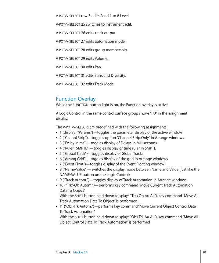
V-POT/V-SELECT row 3 edits Send 1 to 8 Level.
V-POT/V-SELECT 25 switches to Instrument edit.
V-POT/V-SELECT 26 edits track output.
V-POT/V-SELECT 27 edits automation mode.
V-POT/V-SELECT 28 edits group membership.
V-POT/V-SELECT 29 edits Volume.
V-POT/V-SELECT 30 edits Pan.
V-POT/V-SELECT 31 edits Surround Diversity.
V-POT/V-SELECT 32 edits Track Mode.
Function OverlayWhile the FUNCTION button light is on, the Function overlay is active.
A Logic Control in the same control surface group shows “FU” in the assignment display.
The V-POT/V-SELECTs are predefined with the following assignments:• 1 (display: “Params”)—toggles the parameter display of the active window• 2 (“Channl Strip”)—toggles option “Channel Strip Only” in Arrange windows• 3 (“Delay in ms”)—toggles display of Delays in Milliseconds• 4 (“Ruler: SMPTE”)—toggles display of time ruler in SMPTE• 5 (“Global Track”)—toggles display of Global Tracks• 6 (“Arrang Grid”)—toggles display of the grid in Arrange windows• 7 (“Event Float”)—toggles display of the Event Floating window• 8 (“Name/Value”)—switches the display mode between Name and Value (just like the
NAME/VALUE button on the Logic Control)• 9 (“Track Autom.”)—toggles display of Track Automation in Arrange windows• 10 (“Trk>Ob Autom.”)—performs key command “Move Current Track Automation
Data To Object”With the SHIFT button held down (display: “Trk>Ob Au All”), key command “Move All Track Automation Data To Object” is performed
• 11 (“Ob>Trk Autom.”)—performs key command “Move Current Object Control Data To Track Automation”With the SHIFT button held down (display: “Ob>Trk Au All”), key command “Move All Object Control Data To Track Automation” is performed
Chapter 3 Mackie C4 81

82
• 12 (“Clear Autom.”)—performs key command “Delete currently visible Automation Data of Current Track”With the SHIFT button held down (display: “Clear Au All”), key command “Delete All Automation Data of Current Track” is performed
• 13 (“ClrAll Overld”)—resets the Level Meter Overload displays• 14 (“ClrAll RecRdy”)—switches off Record Ready for all tracks• 15 (“ClrAll Solo”)—switches off Solo for all tracks• 16 (“ClrAll Mute”)—switches off Mute for all tracks• 17 (“Tool: Arrow”)—chooses the Arrow tool• 18 (“Tool: Pencil”)—chooses the Pencil tool• 19 (“Tool: Scissr”)—chooses the Scissors tool• 20 (“Tool: Glue”)—chooses the Glue tool• 21 (“Tool: Text”)—chooses the Text tool• 22 (“Tool: Xfade”)—chooses the Crossfade tool• 23 (“Tool: Marque”)—chooses the Marquee tool• 24 (“Tool: Autom.”)—chooses the Automation tool• V-POT 25 (“WfZoom”)—edits the active Arrange window’s waveform zoom factor• V-POT 26 (“V.Zoom”)—edits the active window’s vertical zoom factor• V-POT 27 (“H.Zoom”)—edits the active window’s horizontal zoom factor• V-POT 28 (“Move Cycle”)—moves the Cycle locators• V-POT 29 (“Quantz”)—chooses the “Quantize Again” value
V-SELECT 29 performs “Quantize Again” for the selected regions or events• V-POT 30 (“Format”)—chooses the Format value for clock display• V-SELECT 31 (“Prev SetEXS”)—performs key command “Next Plug-In Setting or EXS
Instrument”• V-SELECT 32 (“Next SetEXS”)—performs key command “Previous Plug-In Setting or
EXS Instrument”
Holding down the SHIFT button currently only has V-SELECTs 10 to 12 assigned (see above); holding down the OPTION, CTRL or CMD/ALT buttons currently contains no assignments, so you can assign new key commands in these views. Of course you can also reassign the existing assignments.
Chapter 3 Mackie C4
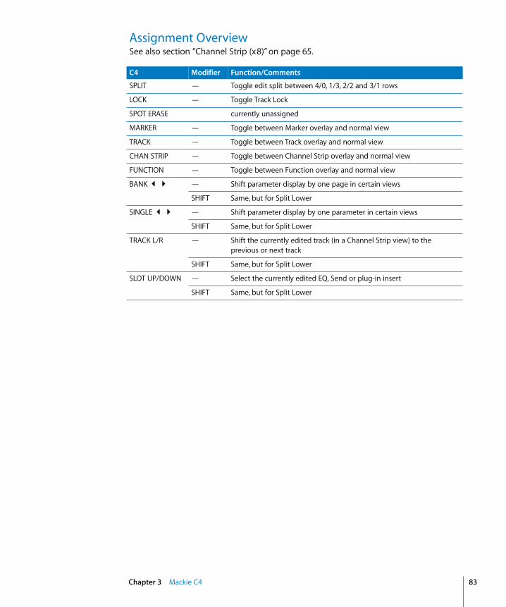
Assignment OverviewSee also section “Channel Strip (x8)” on page 65.
C4 Modifier Function/Comments
SPLIT — Toggle edit split between 4/0, 1/3, 2/2 and 3/1 rows
LOCK — Toggle Track Lock
SPOT ERASE currently unassigned
MARKER — Toggle between Marker overlay and normal view
TRACK — Toggle between Track overlay and normal view
CHAN STRIP — Toggle between Channel Strip overlay and normal view
FUNCTION — Toggle between Function overlay and normal view
BANK 34 — Shift parameter display by one page in certain views
SHIFT Same, but for Split Lower
SINGLE 34 — Shift parameter display by one parameter in certain views
SHIFT Same, but for Split Lower
TRACK L/R — Shift the currently edited track (in a Channel Strip view) to the previous or next track
SHIFT Same, but for Split Lower
SLOT UP/DOWN — Select the currently edited EQ, Send or plug-in insert
SHIFT Same, but for Split Lower
Chapter 3 Mackie C4 83


4
4 Tascam FW-1884IntroductionLogic supports the Tascam FW-1884 and FE-8 extension.
Version 1.10 also supports the SoftLCD application which displays information on track names, parameter assignment and current value of the encoders. While one of the automation mode buttons is held down, SoftLCD displays the tracks’ current automation mode, and encoder edits it.
Alerts are displayed in SoftLCD. Select buttons allow to remote-control alert buttons.
RequirementsYou need• one or more FW-1884, optionally one or more FE-8• Logic Pro 7 or Logic Express 7 or newer
Set Up• Make sure that the FW-1884’s MIDI driver is installed. See the FW-1884
documentation for details• Connect the FW-1884 using the FireWire cable• The FW-1884 and FE-8 units are installed automatically.• If you have multiple units, place their icons in the Setup window left to right so that
they have the same order as the physical units.
OperationSee the Assignment overview section.
The FE-8 extensions only have the Channel Strip section, so the other sections don’t apply here. The FW-1884 ENCODERS section also applies to the FE-8 channel strips.
85

86
Assignment OverviewA right-aligned modifier button below a button description means: while holding down this modifier, the button has this alternate meaning.
ENCODERS Section
SHORTCUTS Section
Control Assignment
FLIP toggles Flip Mode between Off and Swap
PAN assigns Pan to encoders
AUX 1 assigns Send 1 Level to encoders
AUX 2 assigns Send 2 Level to encoders
AUX 3 assigns Send 3 Level to encoders
AUX 4 assigns Send 4 Level to encoders
AUX 5 assigns Send 5 Level to encoders
AUX 6 assigns Send 6 Level to encoders
AUX 7 assigns Send 7 Level to encoders
AUX 8 assigns Send 8 Level to encoders
Control Assignment
SAVE/F1 saves the active song. The button’s LED is on when the song has been edited.
REVERT/F2 reverts the active song to the saved version.
ALL SAFE/F3 disables Record Ready for all tracks
CLR SOLO/F4
switches Solo off on all tracks
SHIFT switches Mute off on all tracks
MARKERS/F5 creates a new marker at the current song position line
SHIFT deletes the marker at the SPL
LOOP/F6 Toggles Cycle mode
CUT cuts the current selection and puts it in the clipboard
DEL deletes the current selection
COPY copies the current selection to the clipboard
PASTE pastes the clipboard
ALT/CMD Modifier for other buttons. See their description
UNDO performs Undo. The button LED is on when Redo is possible.
SHIFT performs Redo
SHIFT Modifier for other buttons. See their description
CTRL Modifier for other buttons. See their description
Chapter 4 Tascam FW-1884

Channel strips
EQ SectionThe EQ controls apply to a certain EQ band of the selected track. A Channel EQ must be inserted in the track (or the song must use the old, pre 6.0 EQs).
Control Assignment
REC LEDs These LEDs are on when the corresponding track is recording and flash when the track is Record Ready
SEL selects the track
SHIFT when encoders control a Send Level, toggles Send Mute
READ sets the track’s automation mode to Read
WRITE sets the track’s automation mode to Write
TCH sets the track’s automation mode to Touch
LATCH sets the track’s automation mode to Latch
SOLO toggles the Solo status of the track
MUTE toggles the Mute status of the track
Encoder controls parameter chosen with the ENCODERS section
SET when ENCODERS section has chosen Send editing, sets the Send’s destination
Fader controls volume of the track
Mode Assignment
REC while held down, the SEL buttons in the channel strips toggle Record Ready status
GAIN edits Gain of currently selected EQ band
SET selects Track input
FREQ edits Frequency of currently selected EQ band
SET selects Track output
Q edits Q factor of currently selected EQ band
SET selects Track mode
HIGH selects parametric EQ band 4 (for Channel EQ)
SHIFT selects High Cut (for Channel EQ)
HI-MID selects parametric EQ band 3 (for Channel EQ)
SHIFT selects High Shelf (for Channel EQ)
LOW-MID selects parametric EQ band 2 (for Channel EQ), or EQ band 4 (for pre-6.0 EQs)
SHIFT selects Low Shelf (for Channel EQ), or EQ band 2 (for pre-6.0 EQs)
LOW selects parametric EQ band 1 (for Channel EQ), or EQ band 3 (for pre-6.0 EQs)
SHIFT selects Low Cut (for Channel EQ), or EQ band 1 (for pre-6.0 EQs)
Chapter 4 Tascam FW-1884 87

88
MASTER faderThis fader always controls the master volume. If no Master object exists in the environment, it controls Output 1-2.
Master SectionControl Assignment
READ while held down, SEL buttons are on if a track has Read automation mode. Pressing the SEL button sets Read mode. Turning the encoder also edits the automation mode.
WRITE while held down, SEL buttons are on if a track has Write automation mode. Pressing the SEL button sets Write mode. Turning the encoder also edits the automation mode.
TCH while held down, SEL buttons are on if a track has Touch automation mode. Pressing the SEL button sets Touch mode. Turning the encoder also edits the automation mode.
LATCH while held down, SEL buttons are on if a track has Latch automation mode. Pressing the SEL button sets Latch mode. Turning the encoder also edits the automation mode.
F7 switches encoders to editing of surround parameters on selected track: angle, radius, LFE, surround mode, X, Y
F8 switches encoders to EQ editing on selected track. For parameter assignment, see upper line on SoftLCD. Cursor left/right shifts parameter bank.
F9 switches Encoders to plug-in editing on selected track. Cursor left/right shifts parameter bank; Cursor up/down chooses insert to edit
F10 switches encoders to instrument editing on selected track. Cursor left/right shifts parameter bank.
Cursorbuttons
like computer keyboard cursor keys; except while encoders are in EQ, plug-in or instrument editing mode (see above)
SHIFT zooms in and out horizontally or vertically
SHTL Enables Shuttle mode for Wheel
Wheel Shuttle mode off: moves SPL by barShuttle mode on: shuttles SPL
Bank LEDs Show currently selected fader bank. With only an FW-1884 installed, a bank means 8 tracks. If you have FE-8 extensions added, a bank means the entire number of channel strips, e.g. 16, 24 etc.If no LED is on, a bank higher 4 is selected.
BANKbuttons
shifts fader bank up or down by one bank
SHIFT shifts fader bank up or down by one track
LOCATEbuttons
goes to previous or next marker
NUDGEbuttons
nudges the selected objects left or right (by the current nudge value)
SET chooses the current nudge value, in the order Tick, Format, Denominator, Bar, Frame, 1/2 Frame
SET modifier for other buttons. See their description.
IN goes to left locator
Chapter 4 Tascam FW-1884
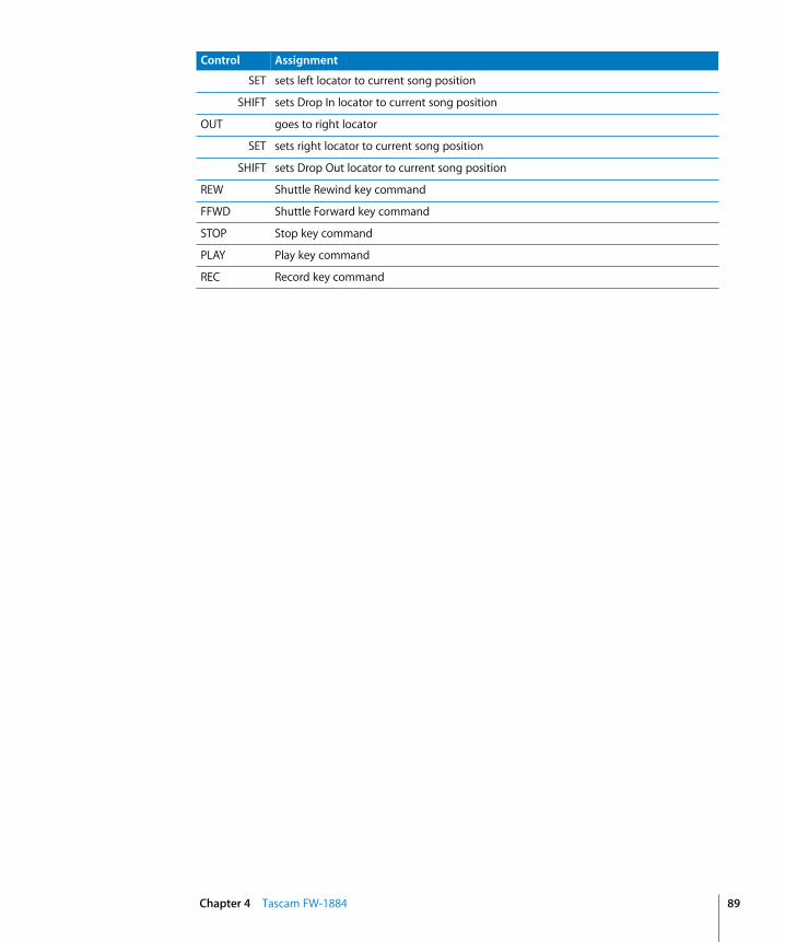
SET sets left locator to current song position
SHIFT sets Drop In locator to current song position
OUT goes to right locator
SET sets right locator to current song position
SHIFT sets Drop Out locator to current song position
REW Shuttle Rewind key command
FFWD Shuttle Forward key command
STOP Stop key command
PLAY Play key command
REC Record key command
Control Assignment
Chapter 4 Tascam FW-1884 89


5
5 Mackie HUIRequirementsYou need• a HUI or compatible product• Logic Pro 7 or newer
Set Up• Make sure that an XSKey with a Logic Pro 7 authorization is connected.• Make sure that your HUI unit(s) are connected bidirectionally with the computer,
using a MIDI interface.• Choose menu item Logic Pro > Control Surfaces > Setup…• Choose menu item New > Install… in the Setup window’s local menu.• For every HUI unit, select HUI in the Install window, choose Add, then set the
appropriate MIDI In and Out ports in the Setup window.
Other HUI-compatible DevicesIf the unit emulates one HUI unit, proceed as if you have a HUI.
If you experience problems in the DSP Edit display, instead install the unit as a DM2000.
If the unit emulates more than one HUI, add an according number of additional devices in the setup, similarly as for the Yamaha digital mixers. If the unit supports only one HUI DSP edit section, choose HUI Channel Strips only as the model name for the additional units. This ensures that scrolling in the DSP edit section scrolls by four parameters.
For the the assignment of the buttons, refer to section Assignment Overview chapter, from page 92 and the device’s user manual.
91

92
Assignment OverviewA right-aligned modifier button below a button description means: while holding down this modifier, the button has this alternate meaning.
ASSIGN SectionControl Assignment
SEND A assigns Send 1 Level to V-POTs, and Send 1 to 4 Levels to DSP V-POTs. While held down, the scribble strips show the current Send 1 destination assignment
SHIFT/ADD as above, but Send 6
SEND B assigns Send 2 Level to V-POTs, and Send 1 to 4 Levels to DSP V-POTs. While held down, the scribble strips show the current Send 2 destination assignment
SHIFT/ADD as above, but Send 7
SEND C assigns Send 3 Level to V-POTs, and Send 1 to 4 Levels to DSP V-POTs. While held down, the scribble strips show the current Send 3 destination assignment
SHIFT/ADD as above, but Send 8
SEND D assigns Send 4 Level to V-POTs, and Send 1 to 4 Levels to DSP V-POTs. While held down, the scribble strips show the current Send 4 destination assignment
SEND E assigns Send 5 Level to V-POTs, and Send 5 to 8 Levels to DSP V-POTs. While held down, the scribble strips show the current Send 5 destination assignment
PAN assigns Pan to V-POTs; assigns selected track’s pan/surround parameters to DSP V-POTs
INPUT assigns Track Input to V-POTs. While held down, the scribble strips show the current Track Input assignment
OUTPUT assigns Track Output to V-POTs. While held down, the scribble strips show the current Track Output assignment
REC/RDY ALL Disable Record Ready on all tracks
BYPASS toggles the INSERT buttons between Insert Select and Insert Bypass mode
MUTE toggles the V-SELECT buttons between Send Position and Send Mute mode
SHIFT toggles Flip mode
SELECT-ASSIGN displays the V-POT assignment as follows:Pan, Snd1 to Snd8, S1As to S8As, In, Out
SUSPEND —
DEFAULT toggles V-SELECT buttons between normal behavior and setting default value
ASSIGN When V-POTs display a Send level, switches them to Send Destination assignment mode. Press V-SELECT or ASSIGN again to confirm the assignment.
Chapter 5 Mackie HUI

Fader Bank Buttons
WINDOW Section
KEYBOARD SHORTCUTS Section
Control Assignment
Bank Left shifts channel strips by one bank to the left
Bank Right shifts channel strips by one bank to the right
Channel Left shifts channel strips by one channel to the left
Channel Right shifts channel strips by one channel to the right
Control Assignment
TRANSPORT toggles the Transport window
EDIT toggles the Arrange window
MIX toggles the Track Mixer window
ALT toggles the Sample Editor window
STATUS toggles the Audio Pool window
MEM-LOC toggles the Marker List window
Control Assignment
UNDO performs undo
SHIFT/ADD performs redo
OPTION/ALL opens undo history window
SAVE saves the song
OPTION/ALL Save As…: saves the song with a different name
EDIT MODE —
EDIT TOOL selects the next tool. While held down, digit buttons select a specific tool
SHIFT/ADD Shifts to second meaning of some buttonsSee also description of other buttons
OPTION/ALL While held down, value change mode is set to “full”: relative value changes to go minimum or maximumSee also description of other buttons
CTRL/CLUTCH While held down, the Group Clutch is engaged, i.e. all groups are disabled
CMD/ALT/FINE While held down, value change mode is set to “fine”: relative value changes work with maximum resolutionSee also description of other buttons
Chapter 5 Mackie HUI 93

94
Channel StripsControl Assignment
Level Meters display momentary and peak level
REC/RDY toggles Record Ready
OPTION/ALL disables Record Ready for all tracks
INSERT BYPASS off: selects track for plug-in selectionBYPASS on: toggles bypass of currently selected insert slot
V-SEL Pan selected: sets Pan to center if DEFAULT onSend 1 to 8 selected: edits Send Pre/Post, toggles Send Mute or sets Send Level to default valueSend Assign, Input or Output: confirms selection
V-POT adjusts parameter selected in the ASSIGN section
AUTO cycles automation mode.With an automation mode button held down, sets this automation mode
SOLO toggles Solo
OPTION/ALL disables Solo for all tracks
MUTE toggles Mute
OPTION/ALL unmutes all tracks
Scribble Strip displays track name, or Send, In or Out assignment
SELECT selects track
SHIFT/ADD Sets volume to unity level
DEFAULT Sets volume to unity level
Fader adjusts volume, or duplicates V-POT in Flip mode
Chapter 5 Mackie HUI

DSP EDIT/ASSIGN SectionControl Assignment
ASSIGN —
COMPARE toggles DSP display between modes “track name/parameter name” and “parameter name/parameter value”
BYPASS toggles bypass of currently edited plug-in insert
DSP Select 1 to 4
Assignment Pan:• DSP Select 1 sets Pan or Surround Angle to center• DSP Select 2 sets Surround Diversity to center• DSP Select 3 sets Surround LFE to center• DSP Select 4 sets Surround Mode to centerAssignment Send:• toggle Send 1 to 4 or 5 to 8 MutePlug-In Assign:• confirm insert 1 to 4 or 5 to 8 plug-in selection, selects this insert and enters Plug-
In Edit modePlug-In Edit:• sets value to default, or toggles switch
DSP V-POTs Assignment Pan:• DSP V-POT 1 controls Pan or Surround Angle• DSP V-POT 2 controls Surround Diversity• DSP V-POT 3 controls Surround LFE• DSP V-POT 4 controls Surround ModeAssignment Send:• control Send 1 to 4 or 5 to 8 LevelPlug-In Assign:• assigns insert 1 to 4 or 5 to 8 plug-inPlug-In Edit:• sets value to default
INSERT/PARAM toggles between Plug-in Assign and Plug-in Edit modes
SCROLL Plug-In Edit: shifts parameter display by the number of DSP V-POTs in the control surface group (usually four)
CMD/ALT/FINE Plug-In Edit: shifts parameter display by one
Chapter 5 Mackie HUI 95

96
Function Keys
AUTO ENABLE Section
Control Assignment
F1 Clears Overload LEDs
SHIFT/ADD Switches to Global View and enables MIDI Tracks
CMD/ALT/FINE Toggles Arrange window
F2 Recalls Screen Set 2
SHIFT/ADD Switches to Global View and enables Inputs
CMD/ALT/FINE Toggles Track Mixer window
F3 Recalls Screen Set 3
SHIFT/ADD Switches to Global View and enables Audio Tracks
CMD/ALT/FINE Toggles Event Editor window
F4 Recalls Screen Set 4
SHIFT/ADD Switches to Global View and enables Audio Instruments
CMD/ALT/FINE Toggles Score Editor window
F5 Recalls Screen Set 5
SHIFT/ADD Switches to Global View and enables Aux Tracks
CMD/ALT/FINE Toggles Hyper Editor window
F6 Recalls Screen Set 6
SHIFT/ADD Switches to Global View and enables Busses
CMD/ALT/FINE Toggles Matrix Editor window
F7 Toggles counter display between SMPTE and bars/beats/format/ticks
SHIFT/ADD Switches to Global View and enables Outputs and Master object
CMD/ALT/FINE Toggles Transport window
F8/ESC Default: leaves folderGoto Marker: cancels dialog
CMD/ALT/FINE Toggles Audio window
Control Assignment
FADER toggles automation playback and recording of Volume
PAN toggles automation playback and recording of Pan
PLUG IN toggles automation playback and recording of Plug-in parameters
MUTE toggles automation playback and recording of Mute
SEND toggles automation playback and recording of Send Level
SEND MUTE —
Chapter 5 Mackie HUI

AUTO MODE Section
STATUS/GROUP Section
Control Assignment
READ sets selected track to automation mode “Read”. While held down, channel Strip AUTO buttons set automation mode to Read
OPTION/ALL sets all tracks to automation mode “Read”
LATCH sets selected track to automation mode “Latch”. While held down, channel Strip AUTO buttons set automation mode to “Latch”
OPTION/ALL sets all tracks to automation mode “Latch”
TRIM —
TOUCH sets selected track to automation mode “Touch”. While held down, channel Strip AUTO buttons set automation mode to “Touch”
OPTION/ALL sets all tracks to automation mode “Touch”
WRITE sets selected track to automation mode “Write”. While held down, channel Strip AUTO buttons set automation mode to “Write”
OPTION/ALL sets all tracks to automation mode “Write”
OFF sets selected track to automation mode “Off”. While held down, channel Strip AUTO buttons set automation mode to “Off”
OPTION/ALL sets all tracks to automation mode “Off”
Control Assignment
AUTO while held down, the Scribble Strips display the tracks’ automation mode
MONITOR —
PHASE —
GROUP enters Group Edit mode:• the upper line in the DSP edit section displays the currently edited group number
and name• DSP Select buttons 1 to 4 toggle properties of the currently edited group, labelled
in the lower line• When INSERT/PARAM is off, DSP Edit Scroll V-POT scrolls through the group
properties. Otherwise it selects the currently edited group• the SELECT buttons toggle group membership of the track
SHIFT/ADD switches to Track View
CREATE creates a new group and enters Group Edit mode (see above)
SHIFT/ADD switches to Global View
SUSPEND toggles the Group Clutch
SHIFT/ADD switches to Extended Track View
Chapter 5 Mackie HUI 97

98
EDIT Section
Time Display
Control Assignment
CAPTURE —
SEPARATE —
CUT Cuts the selection
COPY Copies the selection
PASTE Pastes the clipboard contents
DELETE Deletes the selection
Control Assignment
TIME CODE checked if counter displays time code
FEET (not assigned)
BEATS checked if counter displays bars/beats/format/ticks
Time display displays time code or bars/beats/format/ticks
RUDE SOLO LIGHT
flashes if any track is soloed
Chapter 5 Mackie HUI

LOCATE/NUMBERS SectionControl Assignment
CLR Deletes current marker
= Creates a marker at the current song position
/ equivalent to computer keyboard / key
* equivalent to computer keyboard * key
- equivalent to computer keyboard – key
+ equivalent to computer keyboard + key
0 to 9 Normal: 1 to 9 recalls marker 1 to 9Goto Marker: equivalent to computer keyboard keys 0 to 9
SHIFT/ADD Switches to Global View and enables1: MIDI Tracks2: Inputs3: Audio Tracks4: Audio Instruments5: Aux Tracks6: Busses7: Outputs and Master object9:0:
EDIT TOOL selects tool:1: arrow2: pencil3: rubber4: text edit5: scissors6: glue7: solo8: mute9: zoom
0 Goto Marker: equivalent to computer keyboard 0 key
. Normal: enters Goto Marker ModeGoto Marker: confirms entered marker number
ENTER Normal: enters folder of selected trackGoto Marker: confirms entered marker number
Chapter 5 Mackie HUI 99

100
Transport SectionControl Assignment
AUDITION —
PRE Sets left locator
IN Sets Drop In locator
OUT Sets Drop Out locator
POST Sets right locator
RTZ goes to the left locator
END goes to the right locator
ON LINE toggles internal/external Sync
LOOP toggles Cycle mode
QUICK PUNCH toggles Drop mode
REWIND Shuttles backward
FAST FWD Shuttles forward
STOP Stop
PLAY Play
SHIFT/ADD Pause
RECORD Record
Chapter 5 Mackie HUI

Cursor Buttons
Jog Wheel
Foot Switches
Control Assignment
Cursor Up Cursor mode: equivalent to computer keyboard arrow up keyZoom mode: zooms out vertically
SHIFT/ADD Zoom mode: Individual track zoom in
CMD/ALT/FINE Page Up
OPTION/ALL +CMD/ALT/FINE
Scroll to top
Cursor Down Cursor mode: equivalent to computer keyboard arrow down keyZoom mode: zooms out vertically
SHIFT/ADD Zoom mode: Individual track zoom out
CMD/ALT/FINE Page Down
OPTION/ALL +CMD/ALT/FINE
Scroll to bottom
Cursor Left Cursor mode: equivalent to computer keyboard arrow left keyZoom mode: zooms out horizontally
SHIFT/ADD Zoom mode: Individual track zoom reset of tracks with same type
CMD/ALT/FINE Page Left
OPTION/ALL +CMD/ALT/FINE
Scroll to left border
Cursor Right Cursor mode: equivalent to computer keyboard arrow right keyZoom mode: zooms in horizontally
SHIFT/ADD Zoom mode: Individual track zoom reset of all tracks
CMD/ALT/FINE Page Right
OPTION/ALL +CMD/ALT/FINE
Scroll to right border
MODE Toggles between Cursor and Zoom mode
Control Assignment
Jog wheel Default: move SPL by one barScrub: scrubbingShuttle: Shuttle mode
SCRUB toggles Scrub mode
SHUTTLE toggles Shuttle mode
Control Assignment
Foot Switch 1 Play or Stop
Foot Switch 2 Record Toggle
Chapter 5 Mackie HUI 101


6
6 Mackie Baby HUIRequirementsYou need• a Baby HUI• Logic Pro 7 or newer
Set Up• Make sure that an XSKey with a Logic Pro 7 authorization is connected.• Make sure that your Baby HUI unit(s) are connected bidirectionally with the
computer.• Choose menu item Logic Pro > Control Surfaces > Setup…• Choose menu item New > Install… in the Setup window’s local menu.• For every Baby HUI unit, select Baby HUI in the Install window, choose Add, then set
the appropriate MIDI In and Out ports in the Setup window.
Assignment OverviewA right-aligned SHIFT below a button description means: while holding down SHIFT, the button has this alternate meaning.
Channel StripsControl Assignment
Rotary encoder adjusts parameter selected in the Encoder Assignment Section
Rotary encoder push button
selects track
SHIFT toggles Record Ready
Signal indicator illuminates when a signal is present in the channel. It also indicates when the channel is selected
MUTE toggles Mute
SOLO toggles Solo
Fader adjusts volume
103

104
Encoder Assignment Section
Automation Section
Display Section
Utility Section
Control Assignment
PAN assigns Pan to Rotary encoders
SEND 1 assigns Send 1 Level to Rotary encoders
SEND 2 assigns Send 2 Level to Rotary encoders
SEND 3 assigns Send 3 Level to Rotary encoders
SEND 4 assigns Send 4 Level to Rotary encoders
Control Assignment
BYPASS/OFF sets selected track to automation mode “Off”.
SHIFT toggles automation playback and recording of Volume
READ sets selected track to automation mode “Read”.
SHIFT toggles automation playback and recording of Mute
WRITE sets selected track to automation mode “Write”.
SHIFT toggles automation playback and recording of Pan
TOUCH sets selected track to automation mode “Touch”.
SHIFT toggles automation playback and recording of Send Level
Control Assignment
TRANSPORT toggles the Transport window
MEM-LOC toggles the Marker List window
MIXER toggles the Track Mixer window
EDIT toggles the Arrange window
Control Assignment
UNDO performs undo
SHIFT Shifts to second meaning of some buttons (labelled below them in a box)
Chapter 6 Mackie Baby HUI

Navigation Section
Transport Section
Control Assignment
RTZ goes to the left locator
SHIFT Sets Drop In locator
END goes to the right locator
SHIFT Sets Drop Out locator
BANK SELECT Left shifts channel strips by one bank to the left
SHIFT shifts channel strips by one channel to the left
BANK SELECT Right
shifts channel strips by one bank to the right
SHIFT shifts channel strips by one channel to the right
Control Assignment
REWIND Shuttles backward
FAST FWD Shuttles forward
STOP Stop
PLAY Play
RECORD Record
Chapter 6 Mackie Baby HUI 105


7
7 Yamaha DM2000RequirementsYou need• a DM2000 or compatible product• Logic Pro 7 or newer
Set Up• Make sure that an XSKey with a Logic Pro 7 authorization is connected.• Make sure that your DM2000 unit(s) are connected with the computer via USB.• Make sure that the MIDI driver which comes with the unit is installed.
At DM2000 Front PanelBasically you set up the DM2000 as if you are using it with Pro Tools. See the DM2000 user manual, section 19. Here are the necessary steps:• Press DISPLAY ACCESS [SETUP], then [F4] (below the LCD). Now move the cursor to the
port parameters right to DAW, select USB and right to it 1-3.• Press DISPLAY ACCESS [REMOTE], then [F1] (below the LCD). For the TARGET parameter,
choose ProTools.• Press LAYER [REMOTE 1]
In LogicWhen Logic Pro is launched, the unit is installed automatically. You should now see three DM2000 icons in the setup window, aligned horizontally.
107

108
Assignment OverviewA right-aligned modifier button below a button description means: while holding down this modifier, the button has this alternate meaning.
MATRIX SELECT Section
AUX SELECT Section
Control Assignment
MATRIX 1 toggles Encoder Push-Switch buttons between normal behavior and setting default value
MATRIX 2 toggles the Encoder Push-Switch buttons between Send Position and Send Mute mode
MATRIX 4 If ENCODER MODE [ASSIGN 4] is on, toggles the channel strip SEL buttons between Insert Select (indicator off ) and Insert Bypass mode (indicator on)
Control Assignment
AUX 1 assigns Send 1 Level to Encoders, and Send 1 to 4 Levels to DSP Encoders. While held down, the Channel Strip displays show the current Send 1 destination assignment
USER 4 as above, but Send 6
AUX 2 assigns Send 2 Level to Encoders, and Send 1 to 4 Levels to DSP Encoders. While held down, the Channel Strip displays show the current Send 2 destination assignment
USER 4 as above, but Send 7
AUX 3 assigns Send 3 Level to Encoders, and Send 1 to 4 Levels to DSP Encoders. While held down, the Channel Strip displays show the current Send 3 destination assignment
USER 4 as above, but Send 8
AUX 4 assigns Send 4 Level to Encoders, and Send 1 to 4 Levels to DSP Encoders. While held down, the Channel Strip displays show the current Send 4 destination assignment
AUX 5 assigns Send 5 Level to Encoders, and Send 5 to 8 Levels to DSP Encoders. While held down, the Channel Strip displays show the current Send 5 destination assignment
Chapter 7 Yamaha DM2000

ENCODER MODE Section
FADER MODE Section
DISPLAY ACCESS Section
Control Assignment
PAN assigns Pan to Encoders; assigns selected track’s pan/surround parameters to DSP Encoders
AUX/MTRX assigns Send 1 Level to Encoders, and Send 1 to 4 Levels to DSP Encoders. While held down, the Channel Strip displays show the current Send 1 destination assignment
ASSIGN 1 assigns Track Input to Encoders. While held down, the Channel Strip displays show the current Track Input assignment
ASSIGN 2 assigns Track Output to Encoders. While held down, the Channel Strip displays show the current Track Output assignment
ASSIGN 3 When Encoders display a Send level, switches them to Send Destination assignment mode. Press Encoder Push-Switch or ASSIGN 3 again to confirm the assignment.
ASSIGN 4 determines mode of channel strip SEL buttons:• indicator off: track selection• indicator on: Insert selection or Insert Bypass, depending on MATRIX SELECT
[MATRIX 4].
Control Assignment
FADER toggles Flip mode
AUX/MTRX toggles Flip mode
Control Assignment
METER Clears Overload LEDs
USER 4 Switches to Global View and enables MIDI Tracks
USER 13 Toggles Arrange window
Chapter 7 Yamaha DM2000 109

110
EFFECTS/PLUG-INS SectionControl Assignment
Display toggles the Sample Editor window
5 —
6 toggles DSP display between modes “track name/parameter name” and “parameter name/parameter value”
7 toggles bypass of currently edited plug-in insert
8 toggles between Plug-in Assign and Plug-in Edit modes
Parameter Up & Parameter Down
Plug-In Edit: shifts parameter display by the number of Parameter controls in the control surface group (usually four)
USER 13 Plug-In Edit: shifts parameter display by one
Parameter control 1–4 push-switch
Assignment Pan:• Parameter control 1 push-switch sets Pan or Surround Angle to center• Parameter control 2 push-switch sets Surround Diversity to center• Parameter control 3 push-switch sets Surround LFE to center• Parameter control 4 push-switch sets Surround Mode to centerAssignment Send:• toggle Send 1 to 4 or 5 to 8 Mute
Plug-In Assign:• confirm insert 1 to 4 or 5 to 8 plug-in selection, selects this insert and enters Plug-
In Edit modePlug-In Edit:• sets value to default, or toggles switch
Parameter controls
Assignment Pan:• Parameter control 1 controls Pan or Surround Angle• Parameter control 2 controls Surround Diversity• Parameter control 3 controls Surround LFE• Parameter control 4 controls Surround ModeAssignment Send:• control Send 1 to 4 or 5 to 8 LevelPlug-In Assign:• assigns insert 1 to 4 or 5 to 8 plug-inPlug-In Edit:• sets value to default
Chapter 7 Yamaha DM2000

LCD
TRACK ARMING Section
Display Assignment
LCD displays parameter details, plug-in selection or plug-in parameters
TIME CODE checked if counter displays time code
FEET (not assigned)
BEATS checked if counter displays bars/beats/format/ticks
Time display displays time code or bars/beats/format/ticks
SELECT ASSIGN displays the Encoder assignment as follows:Pan, Snd1 to Snd8, S1As to S8As, In, Out
Control Assignment
1 to 24 toggles Record Ready
USER 5 disables Record Ready for all tracks
MASTER Disable Record Ready on all tracks
Chapter 7 Yamaha DM2000 111
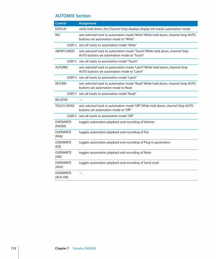
112
AUTOMIX SectionControl Assignment
DISPLAY while held down, the Channel Strip displays display the tracks’ automation mode
REC sets selected track to automation mode “Write”. While held down, channel Strip AUTO buttons set automation mode to “Write”
USER 5 sets all tracks to automation mode “Write”
ABORT/UNDO sets selected track to automation mode “Touch”. While held down, channel Strip AUTO buttons set automation mode to “Touch”
USER 5 sets all tracks to automation mode “Touch”
AUTOREC sets selected track to automation mode “Latch”. While held down, channel Strip AUTO buttons set automation mode to “Latch”
USER 5 sets all tracks to automation mode “Latch”
RETURN sets selected track to automation mode “Read”. While held down, channel Strip AUTO buttons set automation mode to Read
USER 5 sets all tracks to automation mode “Read”
RELATIVE —
TOUCH SENSE sets selected track to automation mode “Off”. While held down, channel Strip AUTO buttons set automation mode to “Off”
USER 5 sets all tracks to automation mode “Off”
OVERWRITE [FADER]
toggles automation playback and recording of Volume
OVERWRITE [PAN]
toggles automation playback and recording of Pan
OVERWRITE [EQ]
toggles automation playback and recording of Plug-in parameters
OVERWRITE [ON]
toggles automation playback and recording of Mute
OVERWRITE [AUX]
toggles automation playback and recording of Send Level
OVERWRITE [AUX ON]
—
Chapter 7 Yamaha DM2000

USER DEFINED KEYS SectionControl Assignment
DISPLAY toggles the Audio Pool window
1 toggles the Transport window
2 shifts channel strips by one bank to the left
3 shifts channel strips by one bank to the right
4 Shifts to second meaning of some buttonsSee also description of other buttons
5 While held down, value change mode is set to “full”: relative value changes to go minimum or maximumSee also description of other buttons
6 enters Group Edit mode:• the upper line in the DSP edit section displays the currently edited group number
and name• Parameter control push-switch buttons 1 to 4 toggle properties of the currently
edited group, labelled in the lower line• When INSERT/PARAM is off, DSP Edit Scroll Encoder scrolls through the group
properties. Otherwise it selects the currently edited group• the SELECT buttons toggle group membership of the track
USER 4 switches to Track View
7 toggles the Group Clutch
USER 4 switches to Extended Track View
8 creates a new group and enters Group Edit mode (see above)
USER 4 switches to Global View
9 toggles between the Arrange and Track Mixer windows
10 shifts channel strips by one channel to the left
11 shifts channel strips by one channel to the right
12 While held down, the Group Clutch is engaged, i.e. all groups are disabled
13 While held down, value change mode is set to “fine”: relative value changes work with maximum resolutionSee also description of other buttons
14 —
15 performs undo
USER 4 performs redo
USER 5 opens undo history window
16 saves the song
USER 5 Save As…: saves the song with a different name
Chapter 7 Yamaha DM2000 113

114
LOCATOR SectionControl Assignment
DISPLAY toggles the Marker List window
1 to 8 recalls marker 1 to 8
USER 4 Switches to Global View and enables1: MIDI Tracks2: Inputs3: Audio Tracks4: Audio Instruments5: Aux Tracks6: Busses7: Outputs and Master object
DISPLAYHISTORY
[FORWARD]
selects tool:1: arrow2: pencil3: rubber4: text edit5: scissors6: glue7: solo8: mute
AUDITION —
PRE Sets left locator
IN Sets Drop In locator
OUT Sets Drop Out locator
POST Sets right locator
RETURN TO ZERO
goes to the left locator
END goes to the right locator
ONLINE toggles internal/external Sync
QUICK PUNCH toggles Drop mode
Chapter 7 Yamaha DM2000
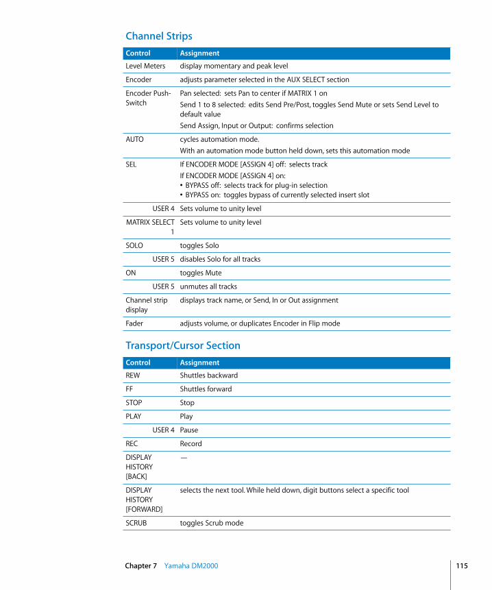
Channel Strips
Transport/Cursor Section
Control Assignment
Level Meters display momentary and peak level
Encoder adjusts parameter selected in the AUX SELECT section
Encoder Push-Switch
Pan selected: sets Pan to center if MATRIX 1 onSend 1 to 8 selected: edits Send Pre/Post, toggles Send Mute or sets Send Level to default valueSend Assign, Input or Output: confirms selection
AUTO cycles automation mode.With an automation mode button held down, sets this automation mode
SEL If ENCODER MODE [ASSIGN 4] off: selects trackIf ENCODER MODE [ASSIGN 4] on:• BYPASS off: selects track for plug-in selection• BYPASS on: toggles bypass of currently selected insert slot
USER 4 Sets volume to unity level
MATRIX SELECT1
Sets volume to unity level
SOLO toggles Solo
USER 5 disables Solo for all tracks
ON toggles Mute
USER 5 unmutes all tracks
Channel strip display
displays track name, or Send, In or Out assignment
Fader adjusts volume, or duplicates Encoder in Flip mode
Control Assignment
REW Shuttles backward
FF Shuttles forward
STOP Stop
PLAY Play
USER 4 Pause
REC Record
DISPLAYHISTORY [BACK]
—
DISPLAYHISTORY [FORWARD]
selects the next tool. While held down, digit buttons select a specific tool
SCRUB toggles Scrub mode
Chapter 7 Yamaha DM2000 115

116
SHUTTLE toggles Shuttle mode
Parameter Wheel
Default: move SPL by one barScrub: scrubbingShuttle: Shuttle mode
DEC Default: leaves FolderGoto Marker: cancels dialog
USER 13 Toggles Audio window
INC Toggles between Cursor and Zoom mode
Cursor Up Cursor mode: equivalent to computer keyboard arrow up keyZoom mode: zooms out vertically
USER 4 Zoom mode: Individual track zoom in
USER 13 Page Up
USER 5+ USER 13
Scroll to top
Cursor Down Cursor mode: equivalent to computer keyboard arrow down keyZoom mode: zooms out vertically
USER 4 Zoom mode: Individual track zoom out
USER 13 Page Down
USER 5+ USER 13
Scroll to bottom
Cursor Left Cursor mode: equivalent to computer keyboard arrow left keyZoom mode: zooms out horizontally
USER 4 Zoom mode: Individual track zoom reset of tracks with same type
USER 13 Page Left
USER 5+ USER 13
Scroll to left border
Cursor Right Cursor mode: equivalent to computer keyboard arrow right keyZoom mode: zooms in horizontally
USER 4 Zoom mode: Individual track zoom reset of all tracks
USER 13 Page Right
USER 5+ USER 13
Scroll to right border
ENTER enters folder of selected track
Control Assignment
Chapter 7 Yamaha DM2000

8
8 Yamaha DM1000RequirementsYou need• a DM1000• Logic Pro 7 or newer
Set Up• Make sure that an XSKey with a Logic Pro 7 authorization is connected.• Make sure that your DM1000 unit(s) are connected with the computer via USB.• Make sure that the MIDI driver which comes with the unit is installed.
At DM1000 Front PanelWhile this document was created, we didn’t have access to DM1000 user documentation, but setting it up for Logic should be similar to the DM2000 setup—see above.
In LogicWhen Logic Pro is launched, the unit is installed automatically. You should now see two DM1000 icons in the setup window, aligned horizontally.
117

118
Assignment OverviewA right-aligned modifier button below a button description means: while holding down this modifier, the button has this alternate meaning.
DISPLAY ACCESS SectionControl Assignment
DISPLAY toggles the Sample Editor window
AUTOMIX while held down, the Channel Strip displays display the tracks’ automation mode
PAIR/GROUP enters Group Edit mode:• the upper line in the DSP edit section displays the currently edited group
number and name• Parameter control push-switch buttons 1 to 4 toggle properties of the
currently edited group, labelled in the lower line• When INSERT/PARAM is off, DSP Edit Scroll Encoder scrolls through the
group properties. Otherwise it selects the currently edited group• the SELECT buttons toggle group membership of the track
DAW SHIFT/ADD switches to Track View
METER Clears Overload LEDs
DAW SHIFT/ADD Switches to Global View and enables MIDI Tracks
DAW ALT/FINE Toggles Arrange window
EFFECT toggles the Sample Editor window
Chapter 8 Yamaha DM1000

AUX SELECT Section
ENCODER MODE Section
FADER MODE Section
Control Assignment
AUX 1 assigns Send 1 Level to Encoders, and Send 1 to 4 Levels to DSP Encoders. While held down, the Channel Strip displays show the current Send 1 destination assignment
DAW SHIFT/ADD as above, but Send 6
AUX 2 assigns Send 2 Level to Encoders, and Send 1 to 4 Levels to DSP Encoders. While held down, the Channel Strip displays show the current Send 2 destination assignment
DAW SHIFT/ADD as above, but Send 7
AUX 3 assigns Send 3 Level to Encoders, and Send 1 to 4 Levels to DSP Encoders. While held down, the Channel Strip displays show the current Send 3 destination assignment
DAW SHIFT/ADD as above, but Send 8
AUX 4 assigns Send 4 Level to Encoders, and Send 1 to 4 Levels to DSP Encoders. While held down, the Channel Strip displays show the current Send 4 destination assignment
AUX 5 assigns Send 5 Level to Encoders, and Send 5 to 8 Levels to DSP Encoders. While held down, the Channel Strip displays show the current Send 5 destination assignment
AUX 6 toggles Encoder Push-Switch buttons between normal behavior and setting default value
AUX 8 determines mode of channel strip SEL buttons while channel strip AUTO button is off:• indicator off: track selection• indicator on: Insert selection
Control Assignment
PAN assigns Pan to Encoders; assigns selected track’s pan/surround parameters to DSP Encoders
AUX assigns Send 1 Level to Encoders, and Send 1 to 4 Levels to DSP Encoders. While held down, the Channel Strip displays show the current Send 1 destination assignment
Control Assignment
FADER MODE toggles Flip mode
Chapter 8 Yamaha DM1000 119

120
LCD Function
LCDThe LCD displays different data, depending on the page you have selected with the buttons F2, F3, and F4:• INSERT ASSIGN/EDIT Display Mode: parameter details, plug-in selection or plug-in
parameters. Press [F2] to select this mode.
Control Assignment
Left & Right Plug-In Edit: shifts parameter display by the number of Parameter controls in the control surface group (usually four)
DAW ALT/FINE Plug-In Edit: shifts parameter display by one
Display Assignment
LCD displays parameter details, plug-in selection or plug-in parameters
TIME CODE checked if counter displays time code
FEET (not assigned)
BEATS checked if counter displays bars/beats/format/ticks
Time display displays time code or bars/beats/format/ticks
SELECT ASSIGN displays the Encoder assignment as follows:Pan, Snd1 to Snd8, S1As to S8As, In, Out
Chapter 8 Yamaha DM1000

LCD Insert Page
Data Entry Section
Control Assignment
ASSIGN —
COMPARE toggles DSP display between modes “track name/parameter name” and “parameter name/parameter value”
BYPASS toggles bypass of currently edited plug-in insert
INSERT/PARAM toggles between Plug-in Assign and Plug-in Edit modes
Parameter control 1 to 4 push-switch
Assignment Pan:• Parameter control 1 push-switch sets Pan or Surround Angle to center• Parameter control 2 push-switch sets Surround Diversity to center• Parameter control 3 push-switch sets Surround LFE to center• Parameter control 4 push-switch sets Surround Mode to centerAssignment Send:• toggle Send 1 to 4 or 5 to 8 MutePlug-In Assign:• confirm insert 1 to 4 or 5 to 8 plug-in selection, selects this insert and
enters Plug-In Edit modePlug-In Edit:• sets value to default, or toggles switch
Parameter controls Assignment Pan:• Parameter control 1 controls Pan or Surround Angle• Parameter control 2 controls Surround Diversity• Parameter control 3 controls Surround LFE• Parameter control 4 controls Surround ModeAssignment Send:• control Send 1 to 4 or 5 to 8 LevelPlug-In Assign:• assigns insert 1 to 4 or 5 to 8 plug-inPlug-In Edit:• sets value to default
Control Assignment
Parameter Wheel Default: move SPL by one barScrub: scrubbingShuttle: Shuttle mode
– (DEC) Default: leaves FolderGoto Marker: cancels dialog
DAW ALT/FINE Toggles Audio window
+ (INC) enters folder of selected track
Chapter 8 Yamaha DM1000 121

122
Channel Strips
Stereo Channel Strip
USER DEFINED KEYS SectionThese keys can be assigned to the following functions:
Control Assignment
Level Meters display momentary and peak level
Encoder adjusts parameter selected in the AUX SELECT section
Encoder Push-Switch Pan selected: sets Pan to center if MATRIX 1 onSend 1 to 8 selected: edits Send Pre/Post, toggles Send Mute or sets Send Level to default valueSend Assign, Input or Output: confirms selection
SEL If AUTO off:• AUX [AUX 8] off: selects track• AUX [AUX 8] on: selects track for insert assignmentIf AUTO on: • cycles automation mode. With an automation mode button held down,
sets this automation mode
DAW SHIFT/ADD Sets volume to unity level
MATRIX SELECT 1 Sets volume to unity level
SOLO toggles Solo
DAW OPTION/ALL disables Solo for all tracks
ON toggles Mute
DAW OPTION/ALL unmutes all tracks
Fader adjusts volume, or duplicates Encoder in Flip mode
Control Assignment
AUTO toggles channel strips’ SEL buttons between track and insert selection
Control Assignment
DAW WIN STATUS toggles the Audio Pool window
DAW REC/RDY 1 to 16 toggles Record Ready
DAW WIN TRANSPORT toggles the Transport window
DAW BANK- shifts channel strips by one bank to the left
DAW BANK+ shifts channel strips by one bank to the right
DAW SHIFT/ADD Shifts to second meaning of some buttonsSee also description of other buttons
DAW OPTION/ALL While held down, value change mode is set to “full”: relative value changes to go minimum or maximumSee also description of other buttons
Chapter 8 Yamaha DM1000

DAW GROUP STATUS enters Group Edit mode:• the upper line in the DSP edit section displays the currently edited group
number and name• Parameter control push-switch buttons 1 to 4 toggle properties of the
currently edited group, labelled in the lower line• When INSERT/PARAM is off, DSP Edit Scroll Encoder scrolls through the
group properties. Otherwise it selects the currently edited group• the SELECT buttons toggle group membership of the track
DAW SHIFT/ADD switches to Track View
DAW SUSPEND toggles the Group Clutch
DAW SHIFT/ADD switches to Extended Track View
DAW CREATE GROUP creates a new group and enters Group Edit mode (see above)
DAW SHIFT/ADD switches to Global View
DAW WIN MIX/EDIT toggles between the Arrange and Track Mixer windows
DAW CHANNEL - shifts channel strips by one channel to the left
DAW CHANNEL+ shifts channel strips by one channel to the right
DAW CTRL/CLUTCH While held down, the Group Clutch is engaged, i.e. all groups are disabled
DAW ALT/FINE While held down, value change mode is set to “fine”: relative value changes work with maximum resolutionSee also description of other buttons
DAW MONI STATUS —
DAW UNDO performs undo
DAW SHIFT/ADD performs redo
DAW OPTION/ALL opens undo history window
DAW SAVE saves the song
DAW WIN MEM-LOC toggles the Marker List window
DAW OPTION/ALL Save As…: saves the song with a different name
DAW EDIT TOOL selects the next tool. While held down, digit buttons select a specific tool
DAW WIN INSERT toggles the Sample Editor window
DAW REC/RDY ALL Disable Record Ready on all tracks
DAW SCRUB toggles Scrub mode
DAW SHUTTLE toggles Shuttle mode
DAW REW Shuttles backward
DAW FF Shuttles forward
DAW STOP Stop
DAW PLAY Play
DAW SHIFT/ADD Pause
DAW REC Record
Control Assignment
Chapter 8 Yamaha DM1000 123

124
DAW PRE Sets left locator
DAW IN Sets Drop In locator
DAW OUT Sets Drop Out locator
DAW POST Sets right locator
DAW RTZ goes to the left locator
DAW END goes to the right locator
DAW ONLINE toggles internal/external Sync
DAW QUICK PUNCH toggles Drop mode
DAW AUTO FADER toggles automation playback and recording of Volume
DAW AUTO PAN toggles automation playback and recording of Pan
DAW AUTO PLUGIN toggles automation playback and recording of Plug-in parameters
DAW AUTO MUTE toggles automation playback and recording of Mute
DAW AUTO SEND toggles automation playback and recording of Send Level
DAW AUTO SEND MUTE
—
DAW AUTO WRITE sets selected track to automation mode “Write”. While held down, channel Strip AUTO buttons set automation mode to “Write”
DAW OPTION/ALL sets all tracks to automation mode “Write”
DAW AUTO TOUCH sets selected track to automation mode “Touch”. While held down, channel Strip AUTO buttons set automation mode to “Touch”
DAW OPTION/ALL sets all tracks to automation mode “Touch”
DAW AUTO LATCH sets selected track to automation mode “Latch”. While held down, channel Strip AUTO buttons set automation mode to “Latch”
DAW OPTION/ALL sets all tracks to automation mode “Latch”
DAW AUTO READ sets selected track to automation mode “Read”. While held down, channel Strip AUTO buttons set automation mode to Read
DAW OPTION/ALL sets all tracks to automation mode “Read”
DAW AUTO TRIM —
DAW AUTO OFF sets selected track to automation mode “Off”. While held down, channel Strip AUTO buttons set automation mode to “Off”
DAW OPTION/ALL sets all tracks to automation mode “Off”
DAW AUTO STATUS while held down, the Channel Strip displays display the tracks’ automation mode
Control Assignment
Chapter 8 Yamaha DM1000

9
9 Yamaha 02R96RequirementsYou need• a 02R96• Logic Pro 7 or newer
Set Up• Make sure that an XSKey with a Logic Pro 7 authorization is connected.• Make sure that your 02R96 unit(s) are connected with the computer via USB.• Make sure that the MIDI driver which comes with the unit is installed.
At 02R96 Front PanelBasically you set up the 02R96 as if you are using it with Pro Tools. See the 02R96 user manual, section 19. Here are the necessary steps:• Press DISPLAY ACCESS [SETUP], then [F4] (below the LCD). Now move the cursor to the
port parameters right to DAW, select USB and right to it 1-3.• Press DISPLAY ACCESS [REMOTE]. For the TARGET parameter, choose ProTools.• Press LAYER [REMOTE]
In LogicWhen Logic Pro is launched, the unit is installed automatically.
You should now see three 02R96 icons in the setup window, aligned horizontally.
125

126
Assignment OverviewA right-aligned modifier button below a button description means: while holding down this modifier, the button has this alternate meaning.
DISPLAY ACCESS Section
AUX SELECT Section
ENCODER MODE Section
FADER MODE Section
Control Assignment
METER Clears Overload LEDs
Control Assignment
AUX 1 assigns Send 1 Level to Encoders, and Send 1 to 4 Levels to DSP Encoders. While held down, the Channel Strip displays show the current Send 1 destination assignment
AUX 2 assigns Send 2 Level to Encoders, and Send 1 to 4 Levels to DSP Encoders. While held down, the Channel Strip displays show the current Send 2 destination assignment
AUX 3 assigns Send 3 Level to Encoders, and Send 1 to 4 Levels to DSP Encoders. While held down, the Channel Strip displays show the current Send 3 destination assignment
AUX 4 assigns Send 4 Level to Encoders, and Send 1 to 4 Levels to DSP Encoders. While held down, the Channel Strip displays show the current Send 4 destination assignment
AUX 5 assigns Send 5 Level to Encoders, and Send 5 to 8 Levels to DSP Encoders. While held down, the Channel Strip displays show the current Send 5 destination assignment
Control Assignment
PAN assigns Pan to Encoders; assigns selected track’s pan/surround parameters to DSP Encoders
AUX assigns Send 1 Level to Encoders, and Send 1 to 4 Levels to DSP Encoders. While held down, the Channel Strip displays show the current Send 1 destination assignment
Control Assignment
FADER toggles Flip mode
AUX/MTRX toggles Flip mode
Chapter 9 Yamaha 02R96

EFFECTS/PLUG-INS SectionControl Assignment
Display toggles the Sample Editor window
PLUG-INS toggles Encoder Push-Switch buttons between normal behavior and setting default value
CHANNEL INSERTS
determines mode of channel strip SEL buttons:• indicator off: track selection• indicator on: Insert selection
1 —
2 toggles DSP display between modes “track name/parameter name” and “parameter name/parameter value”
3 toggles bypass of currently edited plug-in insert
4 toggles between Plug-in Assign and Plug-in Edit modes
Parameter Up & Parameter Down
Plug-In Edit: shifts parameter display by the number of Parameter controls in the control surface group (usually four)
Parameter control 1–4 push-switch
Assignment Pan:• Parameter control 1 push-switch sets Pan or Surround Angle to center• Parameter control 2 push-switch sets Surround Diversity to center• Parameter control 3 push-switch sets Surround LFE to center• Parameter control 4 push-switch sets Surround Mode to centerAssignment Send:• toggle Send 1 to 4 or 5 to 8 MutePlug-In Assign:• confirm insert 1 to 4 or 5 to 8 plug-in selection, selects this insert and enters Plug-
In Edit modePlug-In Edit:• sets value to default, or toggles switch
Parameter controls
Assignment Pan:• Parameter control 1 controls Pan or Surround Angle• Parameter control 2 controls Surround Diversity• Parameter control 3 controls Surround LFEParameter control 4 controls Surround ModeAssignment Send:• control Send 1 to 4 or 5 to 8 LevelPlug-In Assign:• assigns insert 1 to 4 or 5 to 8 plug-inPlug-In Edit:• sets value to default
Chapter 9 Yamaha 02R96 127

128
LCDThe LCD displays different data, depending on the page you have selected with the buttons F2, F3, and F4 (see page 171ff of the 02R96 user manual):• INSERT ASSIGN/EDIT Display Mode: parameter details, plug-in selection or plug-in
parameters. Press [F2] to select this mode.
• Channel Display Mode: Encoder values and Channel Strip display). Press [F3] to select this mode.
• level meters. Press [F4] to select this mode.
Display Assignment
TIME CODE checked if counter displays time code
FEET (not assigned)
BEATS checked if counter displays bars/beats/format/ticks
Time display displays time code or bars/beats/format/ticks
SELECT ASSIGN displays the Encoder assignment as follows:Pan, Snd1 to Snd8, S1As to S8As, In, Out
Chapter 9 Yamaha 02R96

USER DEFINED KEYS Section
Channel Strips
Control Assignment
DISPLAY while held down, the Channel Strip displays display the tracks’ automation mode
1 toggles between the Arrange and Track Mixer windows
2 toggles the Group Clutch
3 sets selected track to automation mode “Write”. While held down, channel Strip AUTO buttons set automation mode to “Write”
4 sets selected track to automation mode “Touch”. While held down, channel Strip AUTO buttons set automation mode to “Touch”
5 sets selected track to automation mode “Latch”. While held down, channel Strip AUTO buttons set automation mode to “Latch”
6 sets selected track to automation mode “Read”. While held down, channel Strip AUTO buttons set automation mode to Read
7 —
8 sets selected track to automation mode “Off”. While held down, channel Strip AUTO buttons set automation mode to “Off”
9 shifts channel strips by one bank to the left
10 shifts channel strips by one bank to the right
11 toggles automation playback and recording of Volume
12 toggles automation playback and recording of Mute
13 toggles automation playback and recording of Pan
14 toggles automation playback and recording of Send Level
15 —
16 toggles automation playback and recording of Plug-in parameters
Control Assignment
Encoder adjusts parameter selected in the AUX SELECT section
Encoder Push-Switch
Pan selected: sets Pan to center if EFFECTS/PLUG-INS [PLUG-INS] onSend 1 to 8 selected: edits Send Pre/Post, toggles Send Mute or sets Send Level to default valueSend Assign, Input or Output: confirms selection
AUTO cycles automation mode.With an automation mode button held down, sets this automation mode
SEL If EFFECTS/PLUG-INS [CHANNEL INSERTS] off: selects trackIf EFFECTS/PLUG-INS [CHANNEL INSERTS] on: selects track for plug-in selection
SOLO toggles Solo
ON toggles Mute
Fader adjusts volume, or duplicates Encoder in Flip mode
Chapter 9 Yamaha 02R96 129

130
MACHINE CONTROL Section
Data Entry Section
Control Assignment
DISPLAY toggles the Marker List window
1 to 8 recalls marker 1 to 8
REW Shuttles backward
FF Shuttles forward
STOP Stop
PLAY Play
REC Record
Control Assignment
SCRUB toggles Scrub mode
SHUTTLE toggles Shuttle mode
Parameter Wheel
Default: move SPL by one barScrub: scrubbingShuttle: Shuttle mode
ENTER enters folder of selected track
DEC leaves Folder
INC Toggles between Cursor and Zoom mode
Cursor Up Cursor mode: equivalent to computer keyboard arrow up keyZoom mode: zooms out vertically
Cursor Down Cursor mode: equivalent to computer keyboard arrow down keyZoom mode: zooms out vertically
Cursor Left Cursor mode: equivalent to computer keyboard arrow left keyZoom mode: zooms out horizontally
Cursor Right Cursor mode: equivalent to computer keyboard arrow right keyZoom mode: zooms in horizontally
Chapter 9 Yamaha 02R96
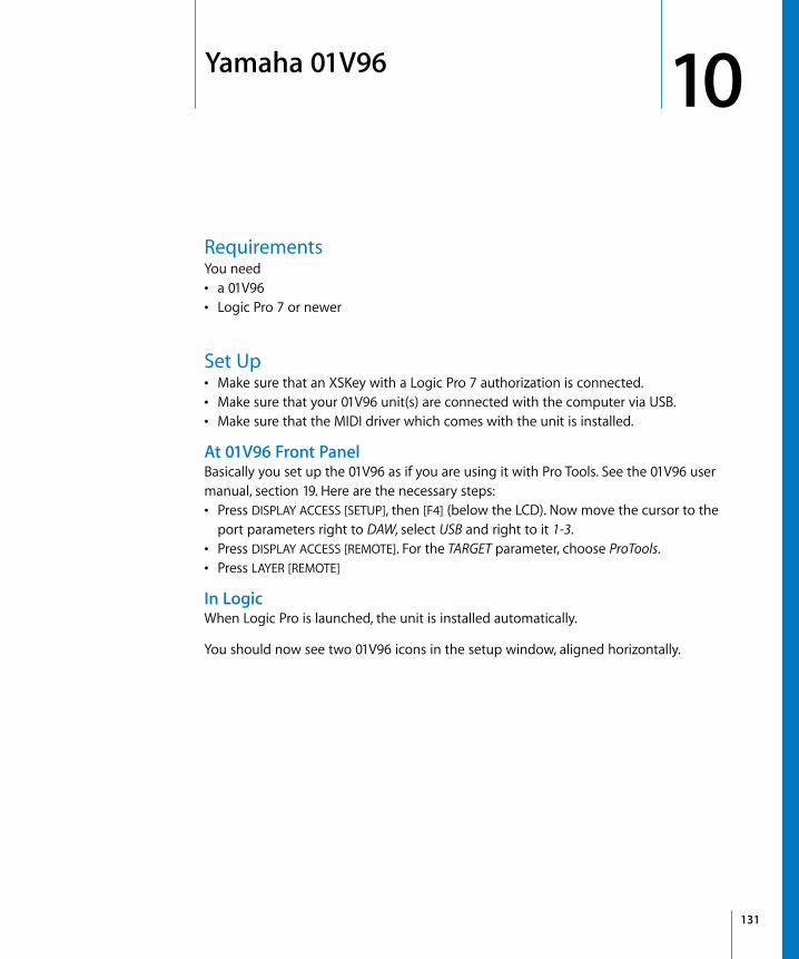
10
10 Yamaha 01V96RequirementsYou need• a 01V96• Logic Pro 7 or newer
Set Up• Make sure that an XSKey with a Logic Pro 7 authorization is connected.• Make sure that your 01V96 unit(s) are connected with the computer via USB.• Make sure that the MIDI driver which comes with the unit is installed.
At 01V96 Front PanelBasically you set up the 01V96 as if you are using it with Pro Tools. See the 01V96 user manual, section 19. Here are the necessary steps:• Press DISPLAY ACCESS [SETUP], then [F4] (below the LCD). Now move the cursor to the
port parameters right to DAW, select USB and right to it 1-3.• Press DISPLAY ACCESS [REMOTE]. For the TARGET parameter, choose ProTools.• Press LAYER [REMOTE]
In LogicWhen Logic Pro is launched, the unit is installed automatically.
You should now see two 01V96 icons in the setup window, aligned horizontally.
131

132
Assignment OverviewA right-aligned modifier button below a button description means: while holding down this modifier, the button has this alternate meaning.
DISPLAY ACCESS Section
FADER MODE Section
Control Assignment
DISPLAY toggles the Sample Editor window
AUTOMIX while held down, the Channel Strip displays display the tracks’ automation mode
PAIR/GROUP enters Group Edit mode:• the upper line in the DSP edit section displays the currently edited group
number and name• Parameter control push-switch buttons 1 to 4 toggle properties of the
currently edited group, labelled in the lower line• When INSERT/PARAM is off, DSP Edit Scroll Encoder scrolls through the group
properties. Otherwise it selects the currently edited group• the SELECT buttons toggle group membership of the track
DAW SHIFT/ADD switches to Track View
EFFECT toggles the Sample Editor window
Control Assignment
AUX 1 assigns Send 1 Level to Encoders, and Send 1 to 4 Levels to DSP Encoders. While held down, the Channel Strip displays show the current Send 1 destination assignment
DAW SHIFT/ADD as above, but Send 6
AUX 2 assigns Send 2 Level to Encoders, and Send 1 to 4 Levels to DSP Encoders. While held down, the Channel Strip displays show the current Send 2 destination assignment
DAW SHIFT/ADD as above, but Send 7
AUX 3 assigns Send 3 Level to Encoders, and Send 1 to 4 Levels to DSP Encoders. While held down, the Channel Strip displays show the current Send 3 destination assignment
DAW SHIFT/ADD as above, but Send 8
AUX 4 assigns Send 4 Level to Encoders, and Send 1 to 4 Levels to DSP Encoders. While held down, the Channel Strip displays show the current Send 4 destination assignment
AUX 5 assigns Send 5 Level to Encoders, and Send 5 to 8 Levels to DSP Encoders. While held down, the Channel Strip displays show the current Send 5 destination assignment
AUX 6 toggles Encoder Push-Switch buttons between normal behavior and setting default value
AUX 7 assigns Pan to Encoders; assigns selected track’s pan/surround parameters to DSP Encoders
Chapter 10 Yamaha 01V96

LCD Function
LCDThe LCD displays different data, depending on the page you have selected with the buttons F2, F3, and F4:• INSERT ASSIGN/EDIT Display Mode: parameter details, plug-in selection or plug-in
parameters. Press [F2] to select this mode.
AUX 8 determines mode of channel strip SEL buttons while channel strip AUTO button is off:• indicator off: track selection• indicator on: Insert selection
HOME toggles Flip mode
Control Assignment
Control Assignment
Left & Right Plug-In Edit: shifts parameter display by the number of Parameter controls in the control surface group (usually four)
DAW ALT/FINE Plug-In Edit: shifts parameter display by one
F1 Clears Overload LEDs
DAW SHIFT/ADD Switches to Global View and enables MIDI Tracks
DAW ALT/FINE Toggles Arrange window
Display Assignment
LCD displays parameter details, plug-in selection or plug-in parameters
TIME CODE checked if counter displays time code
FEET (not assigned)
BEATS checked if counter displays bars/beats/format/ticks
Time display displays time code or bars/beats/format/ticks
SELECT ASSIGN displays the Encoder assignment as follows:Pan, Snd1 to Snd8, S1As to S8As, In, Out
Chapter 10 Yamaha 01V96 133

134
LCD Insert Page
LCD Channel Page
Control Assignment
ASSIGN —
COMPARE toggles DSP display between modes “track name/parameter name” and “parameter name/parameter value”
BYPASS toggles bypass of currently edited plug-in insert
INSERT/PARAM toggles between Plug-in Assign and Plug-in Edit modes
Parameter control 1 to 4 push-switch
Assignment Pan:• Parameter control 1 push-switch sets Pan or Surround Angle to center• Parameter control 2 push-switch sets Surround Diversity to center• Parameter control 3 push-switch sets Surround LFE to center• Parameter control 4 push-switch sets Surround Mode to centerAssignment Send:• toggle Send 1 to 4 or 5 to 8 MutePlug-In Assign:• confirm insert 1 to 4 or 5 to 8 plug-in selection, selects this insert and enters
Plug-In Edit modePlug-In Edit:• sets value to default, or toggles switch
Parameter controls Assignment Pan:• Parameter control 1 controls Pan or Surround Angle• Parameter control 2 controls Surround Diversity• Parameter control 3 controls Surround LFE• Parameter control 4 controls Surround ModeAssignment Send:• control Send 1 to 4 or 5 to 8 LevelPlug-In Assign:• assigns insert 1 to 4 or 5 to 8 plug-inPlug-In Edit:• sets value to default
Control Assignment
Encoder adjusts parameter selected in the FADER MODE section
Encoder Switch Pan selected: sets Pan to center if MATRIX 1 onSend 1 to 8 selected: edits Send Pre/Post, toggles Send Mute or sets Send Level to default valueSend Assign, Input or Output: confirms selection
Chapter 10 Yamaha 01V96

Selected Channel
Data Entry Section
Channel Strips
Stereo Channel Strip
Control Assignment
Pan Encoder adjusts parameter selected in the FADER MODE section
SEL toggles channel strips’ SEL buttons between track and insert selection
Control Assignment
Parameter Wheel Default: move SPL by one barScrub: scrubbingShuttle: Shuttle mode
– (DEC) Default: leaves FolderGoto Marker: cancels dialog
DAW ALT/FINE Toggles Audio window
+ (INC) enters folder of selected track
Control Assignment
Level Meters display momentary and peak level
SEL If AUTO off:• FADER MODE [AUX 8] off: selects track• FADER MODE [AUX 8] on: selects track for insert assignmentIf AUTO on: • cycles automation mode. With an automation mode button held down, sets
this automation mode
DAW SHIFT/ADD Sets volume to unity level
MATRIX SELECT 1 Sets volume to unity level
SOLO toggles Solo
DAW OPTION/ALL disables Solo for all tracks
ON toggles Mute
DAW OPTION/ALL unmutes all tracks
Fader adjusts volume, or duplicates Encoder in Flip mode
Control Assignment
SEL toggles channel strips’ SEL buttons between track and insert selection
Chapter 10 Yamaha 01V96 135

136
USER DEFINED KEYS SectionThese keys can be assigned to the following functions:
Control Assignment
DAW WIN STATUS toggles the Audio Pool window
DAW REC/RDY 1 to 16 toggles Record Ready
DAW WIN TRANSPORT toggles the Transport window
DAW BANK- shifts channel strips by one bank to the left
DAW BANK+ shifts channel strips by one bank to the right
DAW SHIFT/ADD Shifts to second meaning of some buttonsSee also description of other buttons
DAW OPTION/ALL While held down, value change mode is set to “full”: relative value changes to go minimum or maximumSee also description of other buttons
DAW GROUP STATUS enters Group Edit mode:• the upper line in the DSP edit section displays the currently edited group
number and name• Parameter control push-switch buttons 1 to 4 toggle properties of the
currently edited group, labelled in the lower line• When INSERT/PARAM is off, DSP Edit Scroll Encoder scrolls through the
group properties. Otherwise it selects the currently edited group• the SELECT buttons toggle group membership of the track
DAW SHIFT/ADD switches to Track View
DAW SUSPEND toggles the Group Clutch
DAW SHIFT/ADD switches to Extended Track View
DAW CREATE GROUP creates a new group and enters Group Edit mode (see above)
DAW SHIFT/ADD switches to Global View
DAW WIN MIX/EDIT toggles between the Arrange and Track Mixer windows
DAW CHANNEL – shifts channel strips by one channel to the left
DAW CHANNEL+ shifts channel strips by one channel to the right
DAW CTRL/CLUTCH While held down, the Group Clutch is engaged, i.e. all groups are disabled
DAW ALT/FINE While held down, value change mode is set to “fine”: relative value changes work with maximum resolutionSee also description of other buttons
DAW MONI STATUS —
DAW UNDO performs undo
DAW SHIFT/ADD performs redo
DAW OPTION/ALL opens undo history window
DAW SAVE saves the song
DAW WIN MEM-LOC toggles the Marker List window
DAW OPTION/ALL Save As…: saves the song with a different name
Chapter 10 Yamaha 01V96

DAW EDIT TOOL selects the next tool. While held down, digit buttons select a specific tool
DAW WIN INSERT toggles the Sample Editor window
DAW REC/RDY ALL Disable Record Ready on all tracks
DAW SCRUB toggles Scrub mode
DAW SHUTTLE toggles Shuttle mode
DAW REW Shuttles backward
DAW FF Shuttles forward
DAW STOP Stop
DAW PLAY Play
DAW SHIFT/ADD Pause
DAW REC Record
DAW PRE Sets left locator
DAW IN Sets Drop In locator
DAW OUT Sets Drop Out locator
DAW POST Sets right locator
DAW RTZ goes to the left locator
DAW END goes to the right locator
DAW ONLINE toggles internal/external Sync
DAW QUICK PUNCH toggles Drop mode
DAW AUTO FADER toggles automation playback and recording of Volume
DAW AUTO PAN toggles automation playback and recording of Pan
DAW AUTO PLUGIN toggles automation playback and recording of Plug-in parameters
DAW AUTO MUTE toggles automation playback and recording of Mute
DAW AUTO SEND toggles automation playback and recording of Send Level
DAW AUTO SEND MUTE —
DAW AUTO WRITE sets selected track to automation mode “Write”. While held down, channel Strip AUTO buttons set automation mode to “Write”
DAW OPTION/ALL sets all tracks to automation mode “Write”
DAW AUTO TOUCH sets selected track to automation mode “Touch”. While held down, channel Strip AUTO buttons set automation mode to “Touch”
DAW OPTION/ALL sets all tracks to automation mode “Touch”
DAW AUTO LATCH sets selected track to automation mode “Latch”. While held down, channel Strip AUTO buttons set automation mode to “Latch”
DAW OPTION/ALL sets all tracks to automation mode “Latch”
DAW AUTO READ sets selected track to automation mode “Read”. While held down, channel Strip AUTO buttons set automation mode to Read
DAW OPTION/ALL sets all tracks to automation mode “Read”
Control Assignment
Chapter 10 Yamaha 01V96 137

138
DAW AUTO TRIM —
DAW AUTO OFF sets selected track to automation mode “Off”. While held down, channel Strip AUTO buttons set automation mode to “Off”
DAW OPTION/ALL sets all tracks to automation mode “Off”
DAW AUTO STATUS while held down, the Channel Strip displays display the tracks’ automation mode
Control Assignment
Chapter 10 Yamaha 01V96

11
11 CM Labs MotormixRequirementsYou need• one or more CM Automation (or CM Labs) Motormix• Logic Pro 7 or newer
Set Up• Make sure that your Motormix unit(s) are connected in both directions with the MIDI
interface.• Choose menu item Logic Pro > Preferences > Control Surfaces > Setup…• Choose menu item New > Install… from the Setup window’s local menu• For every Motormix unit, select “Motormix” in the Install window, choose “Add”, then
set the appropriate MIDI In and Out ports in the Setup window.
Assignment OverviewA right-aligned modifier button below a button description means: while holding down this modifier, the button has this alternate meaning.
VIEW SectionControl Assignment
Left/right buttons
In Plug-in and Instrument Edit mode: shifts the parameter bank by one bankOtherwise:if BANK LED is off:• shifts the fader bank by one channelif BANK LED is on:• shifts the fader bank by one bank
SHIFT In Plug-in and Instrument Edit mode: shifts the parameter bank by one parameterIn Group Edit mode, the group parameter bank is shifted
bank toggles mode of left/right buttons (see above)
SHIFT sets Select buttons to Track View Select mode (see below)
139

140
Select SwitchesThese buttons have multiple purposes, depending on the current mode.
group sets select buttons, rotary encoders and Multi buttons to Group Edit mode
SHIFT displays tracks’ group assignments in the LCD. The rotary encoders allow to change them.
Control Assignment
Mode Assignment
normal selects track displayed in upper LCD line. Tracks can be shifted to the left and right with the View left and right buttons
bank button LED flashing
Track View Select mode: selects type of tracks to be displayed:• 1: Track View• 2: Extended Track View• 3: Global View, MIDI tracks• 4: Global View, Input channels• 5: Global View, Audio tracks• 6: Global View, Audio Instruments• 7: Global View, Bus and Aux channels• 8: Global View, Outputs and Master
WINDOW/tool button LED on
opens, activates or closes a window of a certain classLED off: window is not open; switch opens itLED on: window is open, but not active; switch activates itLED flashes: window is active; switch closes it• 1: Arrange• 2: Track Mixer• 3: Event Editor• 4: Score• 5: Hyper Edit• 6: Matrix Editor• 7: Transport• 8: Audio
WINDOW/tool button flashes
Chooses a tool• 1: arrow• 2: pencil• 3: rubber• 4: text cursor• 5: scissors• 6: glue• 7: solo• 8: mute
Chapter 11 CM Labs Motormix

PLAY/transport button flashes
Transport section• 1: Record• 2: Pause• 3: Stop• 4: Play• 5: Rewind• 6: Fast Forward• Upper row displays current clock
STOP/locate button flashes
Locating functions• 1: goes to left locator• 2: goes to right locator• 3: toggles Cycle• 4: toggles Drop• 5: goes to Marker mode (see below)• 6: opens Marker list floating window• Upper row displays current clock
Marker mode
• 1 to 6: select markers 1 to 6. Their names are displayed in the upper line• 7: creates a new marker• 8: deletes current marker
Group Edit mode
toggles group parameter. Parameter view can be shifted by the View left and right buttons when the SHIFT button is held down.
Mode Assignment
Chapter 11 CM Labs Motormix 141

142
Rotary PotsControl Assignment
Rotary pots 1 to 8
control parameter chosen with the Rotary Selector, as displayed in the 7 segment display (see below)
7 segment display
shows current selection for Rotary pots:Send editing (S-MUTE or PRE/PST LED is on):• S1 to S8 = Send 1 to 8 level• F1 to F8 = EQ band 1 to 8 frequency• G1 to G8 = EQ band 1 to 8 gain• q1 to q8 = EQ band 1 to 8 Q factorPan/Surround editing (select LED is on):• Pn = Pan• An = Surround Angle• dv = Surround Diversity• FE = Surround LFO• Md = Assign Surround Mode• X = Surround X• Y = Surround YTrack parameter editing (eff-4 LED is on):• VL = Volume• Pn or An = Pan/Surround Angle• Md = Channel Mode• In = Channel input• Ou = Channel output• Au = Automation mode• Gr = Group membershipAssignment:• d1 to d8 = Assign Send 1 to 8 destinationPlug-in editing (DSP/compare LED is on):• P1 to 15 = Assign insert 1 to 15 plug-in• P1. to 15. = plug-in parameter editingInstrument editing (DSP/compare LED is on):• IA = Assign instrument• IE. = instrument parameter editingGroup property editing (group LED is on):• G1 to 32 = group number
Rotary Selector
selects a slot or parameter for Rotary encoders, depending on the parameters edited with the rotary encoders:• send slot when editing Send Level or assigning Send destination• EQ band when editing an EQ parameter• plug-in slot when assigning a plug-in• Pan/Surround parameter when editing a Pan/Surround parameter• Track parameter when editing a Track parameter• Plug-in/instrument parameter page when editing a plug-in or instrument
Chapter 11 CM Labs Motormix

Multi ButtonsThese buttons (labelled A to H) have multiple purposes, depending on the current mode, indicated by the green and yellow LEDs to the right.
Rotary Selector push button
toggles Flip Mode between off and Duplicate (i.e. faders duplicate Rotary encoders)
SHIFT toggles Display mode for channel strip displays: switches between• page info in upper line, parameter name in lower line• parameter name in upper line, parameter value in lower line
Control Assignment
Mode Assignment
fx bypass toggles bypass of currently selected insert
SHIFT (eff-1) toggles bypass of currently selected EQ band; switches rotary encoders to EQ Frequency editing
s-mute toggles Send Mute of currently edited Send, switches rotary encoders to Send Level editing
SHIFT (eff-2) toggles bypass of currently selected EQ band; switches rotary encoders to EQ Gain editing
pre/post toggles between Pre and Post of currently edited Send, switches rotary encoders to Send Level editingPost is shown as LED on
SHIFT (eff-3) toggles bypass of currently selected EQ band; switches rotary encoders to EQ Q factor editing
select switches rotary encoders to Pan/Surround editing. The edited parameter is selected with the Rotary Selector.
SHIFT (eff-4) switches rotary encoders to Track Parameter editing
Chapter 11 CM Labs Motormix 143

144
Burn ButtonsThese buttons (labelled I to P) have multiple purposes, depending on the current mode, indicated by the red LEDs to the left.
SOLO ButtonsThese buttons toggle the Solo status of the displayed track.
MUTE ButtonsThese buttons toggle the Mute status of the displayed track.
Mode Assignment
record toggles Record Ready status of track
SHIFT (fnctA) switches automation mode to Latch
ALL + SHIFT (fnctA) switches automation mode of all tracks to Latch
write switches automation mode to Write
ALL switches automation mode of all tracks to Write
SHIFT (fnctB) switches automation mode to Read
ALL + SHIFT (fnctA) switches automation mode of all tracks to Read
burn switches automation mode to Touch
ALL switches automation mode of all tracks to Touch
SHIFT (fnctC) switches automation mode to Off
ALL + SHIFT (fnctA) switches automation mode of all tracks to Off
Chapter 11 CM Labs Motormix

Left Function Buttons
FadersThe faders normally control Volume, except when in Flip Mode, where they duplicate the Rotary Encoders.
Control Assignment
AUTO ENBL/mode currently unassigned
SHIFT switches rotary encoders to automation enable mode
SUSPEND/create While held down, the group clutch is engaged, i.e. groups are disabled
SHIFT creates a new group and goes to Group Edit view
PLUG-IN/compare switches Rotary encoders and Multi buttons to Plug-in Assign mode. The Rotary Select knob then selects the insert to edit.In Plug-in Assign or Instrument Assign mode, switches back to Pan.In Plug-in Edit mode, switches back to Plug-in Assign mode.in Instrument Edit mode, switches back to Instrument Assign mode.
SHIFT switches Rotary encoders and Multi buttons to Instrument Assign mode.
WINDOW/tools switches Select Switches to Window select mode
SHIFT switches Select Switches to Select Tool mode
ALL/alt/fine while ALL/ALT/FINE is held down, rotary encoders are in full mode: rotating counterclockwise sets minimum, rotating clockwise sets maximum
SHIFT while SHIFT and ALL/ALT/FINE are held down, rotary encoders are in fine mode
DEFAULT/bypass currently unassigned
SHIFT in instrument edit mode: toggles bypass of the instrumentin plug-in edit mode: toggles bypass of the currently edited plug-in
UNDO/disk performs an Undo step. The LED is on if there is a Redo step available.
SHIFT saves the song. The LED is on if the song must be saved
SHIFT switches to Shift mode—then the lower case inverted labels below the buttons apply
Chapter 11 CM Labs Motormix 145

146
Right Function ButtonsControl Assignment
PLAY/ transport Play key command
SHIFT switches Select Switches to Transport section mode
STOP/locate Stop key command
SHIFT switches Select Switches to Locate mode
FFWD/monitor Shuttle Forward key command
SHIFT opens System Performance window
RWD/status Shuttle Rewind key command
SHIFT opens Synchronization window
NEXT/configure goes to next marker
LAST/assign When rotary encoders display Send Destinations, switches them back to Send LevelsOtherwise: goes to previous marker
SHIFT When rotary encoders display Send Levels, switches them to Send DestinationWhen rotary encoders edit a plug-in, switches them to Plug-in Assign modeWhen rotary encoders edit an instrument, switches them to Instrument Assign Mode
ENTER/utility same as Enter key on computer keyboard
SHIFT opens Automation Settings window
ESCAPE When LED on, escapes from special mode (whose LED is flashing)Otherwise: same as Esc key on computer keyboard.
Chapter 11 CM Labs Motormix

12
12 Radikal Technologies SAC-2KRequirementsYou need• an SAC-2K or SAC-2.2• Logic Pro 7 or newer
Set Up• Make sure that an XSKey with a Logic Pro 7 authorization.• Make sure that your SAC-2K unit(s) are connected bidirectionally with the computer,
either using a MIDI interface or the USB connector built-in to the unit.• If the unit(s) are connected via USB, make sure that the MIDI driver which comes with
the unit is installed.• Choose menu item Logic Pro > Control Surfaces > Setup…• Choose menu item New > Install… in the Setup window’s local menu• Select the SAC-2K in the install list• Click the Scan button.
Logic should now scan for and install the SAC-2K automatically.
Assignment Overview
A right-aligned modifier button below a button description means: while holding down this modifier, the button has this alternate meaning.
LCDs and EncodersControl Assignment
Left and middle LCDs Upper row displays track number (if in a multi channel view) or parameter name (if in a channel strip view)Lower row displays parameter value of Encoder below.At the right, level meters are displayed.
Right LCD Upper row displays name of parameter edited by Encoder below.Lower row displays parameter value of Encoder below.At the very right, a level meter of the Master Output is displayed.
147
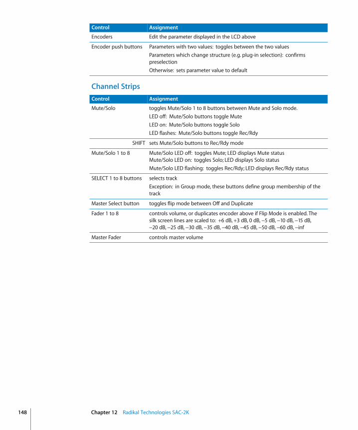
148
Channel Strips
Encoders Edit the parameter displayed in the LCD above
Encoder push buttons Parameters with two values: toggles between the two valuesParameters which change structure (e.g. plug-in selection): confirms preselectionOtherwise: sets parameter value to default
Control Assignment
Control Assignment
Mute/Solo toggles Mute/Solo 1 to 8 buttons between Mute and Solo mode.LED off: Mute/Solo buttons toggle MuteLED on: Mute/Solo buttons toggle SoloLED flashes: Mute/Solo buttons toggle Rec/Rdy
SHIFT sets Mute/Solo buttons to Rec/Rdy mode
Mute/Solo 1 to 8 Mute/Solo LED off: toggles Mute; LED displays Mute statusMute/Solo LED on: toggles Solo; LED displays Solo statusMute/Solo LED flashing: toggles Rec/Rdy; LED displays Rec/Rdy status
SELECT 1 to 8 buttons selects trackException: in Group mode, these buttons define group membership of the track
Master Select button toggles flip mode between Off and Duplicate
Fader 1 to 8 controls volume, or duplicates encoder above if Flip Mode is enabled. The silk screen lines are scaled to: +6 dB, +3 dB, 0 dB, −5 dB, −10 dB, −15 dB, −20 dB, −25 dB, −30 dB, −35 dB, −40 dB, −45 dB, −50 dB, −60 dB, −inf
Master Fader controls master volume
Chapter 12 Radikal Technologies SAC-2K

Mixer-Mode SectionControl Assignment
Pan switches to multi-channel Pan editing.Encoders 9 to 12 edit Pan/Angle, Diversity, LFE and Surround Mode of selected track
High, HiMid, LowMid, Low
switches to multi-channel Gain editing of a certain EQ band. Encoders 9 to 12 edit frequency, gain, Q factor and on/off of the selected track.Pressing and releasing the button chooses a certain band, depending whether the song uses the old or new EQ.Old EQ:• Low: band 3• LowMid: band 4• HiMid: —• High: —New Channel EQ:• Low: band 3 (first parametric EQ band)• LowMid: band 4 (second parametric EQ band)• HiMid: band 5 (third parametric EQ band)• High: band 6 (fourth parametric EQ band)While held down, Encoder 9 lets you choose the EQ band to edit (old EQ: bands 1 to 4; new EQ; bands 1 to 8)The button’s LED is on when in multi-channel Gain editing mode of the button’s EQ band.
Snd/Ins toggles the four Snd/Ins 1 to 4 buttons between Send and Insert mode.LED off: Send modeLED on: Insert mode
Snd/Ins 1 to 4 • If in Send mode, switchs to multi-channel Send Level editing of Send 1 to 4
Encoders 9 to 12 edit Destination, Level, Pre/Post and Mute of the selected track. Destination must be confirmed by Encoder 10’s push-button.While held down, Encoder 9 lets you choose the desired Send number (1 to 8)The button’s LED is on when in multi-channel Send Level editing mode of the button’s Send number.• If in Insert mode, switchs to multi-channel insert plug-in selection of Insert
1 to 4. A plug-in must be confirmed by the Encoder’s push-button.While held down, Encoder 9 lets you choose the desired Insert number (1 to 15)The button’s LED is on when in plug-in selection mode of the button’s insert number.
Audio switches to Global View and displays Audio tracks
SHIFT switches to Mixer View
MIDI switches to Global View and displays MIDI tracks
SHIFT switches to Arrange View
Input switches to Global View and displays Audio Inputs
SHIFT switches to Global View and displays Audio Outputs and Master
Chapter 12 Radikal Technologies SAC-2K 149

150
Software Navigation Section
Inst switches to Global View and displays Audio Instruments
SHIFT switches to Global View and displays Aux objects
Bus switches to Global View and displays Busses
SHIFT switches to Global View and displays folders and other objects
Group switches to Group editing:• Encoder 1 to 10 push buttons edit a group property, labelled in the LCD’s
lower line• Encoder 11 scrolls the group properties• Encoder 12 selects a group to edit. Its name is displayed in the lower line
above Encoder 12• Select buttons 1 to 8 toggle track membership of the group
1 to 8 shifts the fader bank offset left by one bank
9 to 16 shifts the fader bank offset right by one bank
17 to 24 shifts the fader bank offset left by one track
25 to 32 shifts the fader bank offset right by one track
Control Assignment
Control Assignment
1 Num LED off: —Num LED on: equivalent to ‘1’ on computer keyboard
2 Num LED off: equivalent to Cursor Left on computer keyboardNum LED on: equivalent to ‘2’ on computer keyboard
3 Num LED off: equivalent to Cursor Up on computer keyboardNum LED on: equivalent to ‘3’ on computer keyboard
4 Num LED off: equivalent to Cursor Right on computer keyboardNum LED on: equivalent to ‘4’ on computer keyboard
5 Num LED off: UndoNum LED on: equivalent to ‘5’ on computer keyboard
6 Num LED off: —Num LED on: equivalent to ‘6’ on computer keyboard
7 Num LED off: CopyNum LED on: equivalent to ‘7’ on computer keyboard
8 Num LED off: equivalent to Cursor Down on computer keyboardNum LED on: equivalent to ‘8’ on computer keyboard
9 Num LED off: PasteNum LED on: equivalent to ‘9’ on computer keyboard
0 Num LED off: SaveNum LED on: equivalent to ‘0’ on computer keyboard
Chapter 12 Radikal Technologies SAC-2K

Locator SectionThe locator displays the current song position in bars/beats format, as defined in the Song Settings; however spaces between the sections are displayed with a period, as Logic’s bars/beats format may take up up to 14 characters, whereas this display has only 8 digits.
Num Toggles the numeric buttons between primary and secondary function (see above)
Enter same as Enter key on the computer keyboard
Control Assignment
Chapter 12 Radikal Technologies SAC-2K 151

152
Marker Section
Transport Section
Control Assignment
SHIFT shifts to secondary function of other buttons.
Scrub Rotates thru the 3 modes for the jog wheel:• LED off: Move SPL by 1 bar• LED on: Scrub• LED flashes: Shuttle
From Sets left locator to current SPL
SHIFT Sets SPL to left locator
Store Marker Creates a marker at the current SPL
SHIFT Deletes marker at the current SPL
To Sets right locator to current SPL
SHIFT Sets SPL to right locator
Recall Marker Opens the “Goto Marker” dialog
SHIFT Opens the Marker List window
Jog Wheel Moves the SPL in one of three modes, depending on state of Scrub button (see above)
Control Assignment
<< Shuttles backward
SHIFT Goes to previous marker
>> Shuttles forward
SHIFT Goes to next marker
STOP Stop
PLAY Play
SHIFT Toggles Cycle mode
RECORD Record
SHIFT Toggles Replace mode
Chapter 12 Radikal Technologies SAC-2K

Channel-Strips Section
TroubleshootingThe track names are shorter than necessary, and the assignments don’t work correctly.The SAC-2K is in an emulation mode (Logic Control, HUI etc.) for some reason.
To solve this, simply switch off and then on the SAC-2K.
The faders don’t work, and the locator display shows only 00000000.You have switched the SAC-2K mode to SLAVE manually. This however does not initialize some settings required for correct communication.
To solve this, simply switch off and then on the SAC-2K.
Control Assignment
EQs Enters Channel Strip EQ editing mode. Pressing the button again cycles through the available pages.
Inserts/Sends Enters Channel Strip plug-in editing mode—edits the currently selected insert of the selected track. Pressing the button again cycles through the available pages.
Dynamics —
MIDI —
Instrument Enters Channel Strip instrument editing mode—edits the instrument of the selected track (if it’s an Audio Instrument track). Pressing the button again cycles through the available pages.
Chapter 12 Radikal Technologies SAC-2K 153

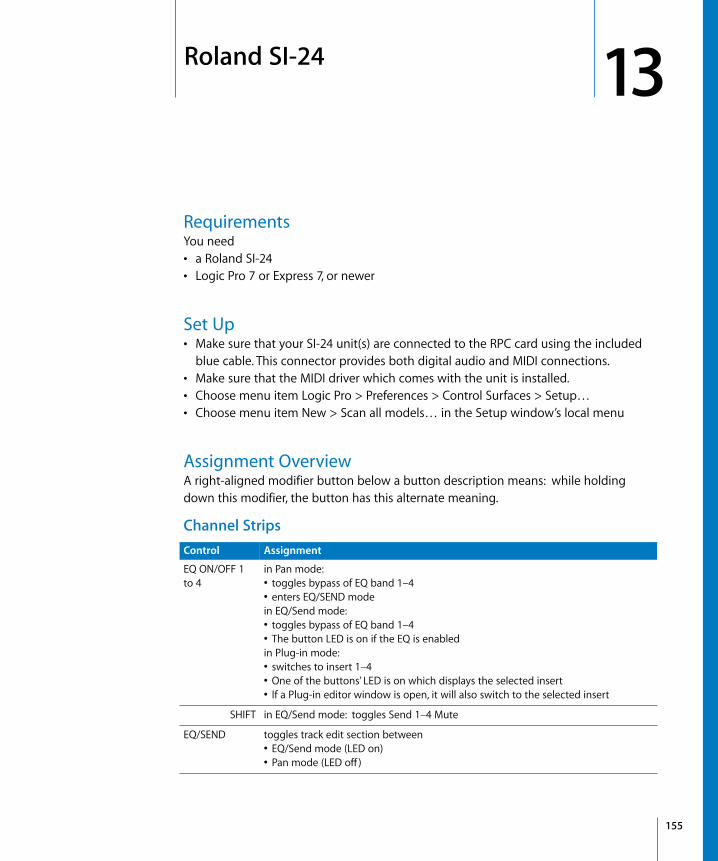
13
13 Roland SI-24RequirementsYou need• a Roland SI-24• Logic Pro 7 or Express 7, or newer
Set Up• Make sure that your SI-24 unit(s) are connected to the RPC card using the included
blue cable. This connector provides both digital audio and MIDI connections.• Make sure that the MIDI driver which comes with the unit is installed.• Choose menu item Logic Pro > Preferences > Control Surfaces > Setup…• Choose menu item New > Scan all models… in the Setup window’s local menu
Assignment OverviewA right-aligned modifier button below a button description means: while holding down this modifier, the button has this alternate meaning.
Channel StripsControl Assignment
EQ ON/OFF 1 to 4
in Pan mode:• toggles bypass of EQ band 1–4• enters EQ/SEND modein EQ/Send mode:• toggles bypass of EQ band 1–4• The button LED is on if the EQ is enabledin Plug-in mode:• switches to insert 1–4• One of the buttons’ LED is on which displays the selected insert• If a Plug-in editor window is open, it will also switch to the selected insert
SHIFT in EQ/Send mode: toggles Send 1–4 Mute
EQ/SEND toggles track edit section between• EQ/Send mode (LED on)• Pan mode (LED off )
155

156
STATUS MODE Section
PLUG-IN toggles track edit section between• Plug-in mode (LED on) (Plug-in editor window opens)• Pan mode (LED off )Plug-in editor window closes when Plug-in mode is left
SHIFT toggles track edit section between• Instrument mode (LED on) (Instrument editor window opens)• Pan mode (LED off )Instrument editor window closes when Instrument mode is left
PAN 1 to 12 in Pan mode:• controls channel strip’s Pan (tracks in surround mode: surround angle)in EQ/Send mode:• 1/3/5/7: EQ 1–4 gain• 2/4/6/8: EQ 1–4 frequency• 9–12: Send 1–4 levelin Plug-in mode:• 1–10: edit plug-in parameter• 11: bypass plug-in• 12: shifts plug-in parameter pagein Instrument mode:• 1–10: edit Instrument parameter• 11: bypass Instrument• 12: shifts Instrument parameter page
SHIFT in EQ/Send mode:• 1/3/5/7: EQ 1–4 type• 2/4/6/8: EQ 1–4 Q factor• 9–12: Send 1–4 destination
CH SELECT 1 to 12
selects track/channel
STATUS 1 to 12 in Automation mode: toggles Automation Mode between• Off (LED off ),• Read (green),• Latch (orange) and• Write (red)in Record Ready mode: toggles Record Readyin Solo mode: toggles Soloin Mute mode: toggles Mute
Fader 1 to 12 controls volume
Control Assignment
Control Assignment
AUTOMIX sets STATUS 1 to 12 buttons to Automation mode
SHIFT sets all tracks to automation mode Off, Read, Latch or Write (rotating)
REC/PLAY sets STATUS 1 to 12 buttons to Record Ready mode
SOLO sets STATUS 1 to 12 buttons to Solo mode
MUTE sets STATUS 1 to 12 buttons to Mute mode
Chapter 13 Roland SI-24
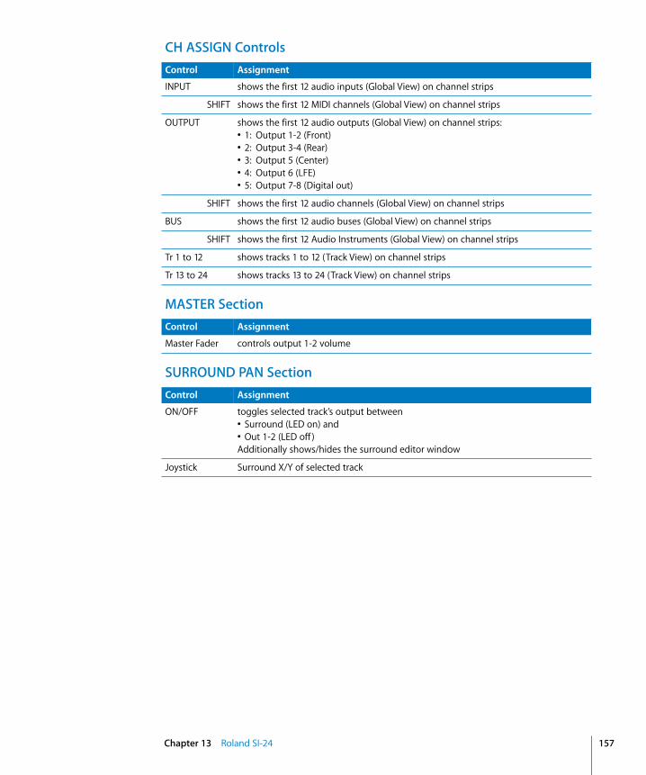
CH ASSIGN Controls
MASTER Section
SURROUND PAN Section
Control Assignment
INPUT shows the first 12 audio inputs (Global View) on channel strips
SHIFT shows the first 12 MIDI channels (Global View) on channel strips
OUTPUT shows the first 12 audio outputs (Global View) on channel strips:• 1: Output 1-2 (Front)• 2: Output 3-4 (Rear)• 3: Output 5 (Center)• 4: Output 6 (LFE)• 5: Output 7-8 (Digital out)
SHIFT shows the first 12 audio channels (Global View) on channel strips
BUS shows the first 12 audio buses (Global View) on channel strips
SHIFT shows the first 12 Audio Instruments (Global View) on channel strips
Tr 1 to 12 shows tracks 1 to 12 (Track View) on channel strips
Tr 13 to 24 shows tracks 13 to 24 (Track View) on channel strips
Control Assignment
Master Fader controls output 1-2 volume
Control Assignment
ON/OFF toggles selected track’s output between• Surround (LED on) and • Out 1-2 (LED off )Additionally shows/hides the surround editor window
Joystick Surround X/Y of selected track
Chapter 13 Roland SI-24 157
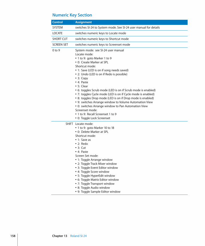
158
Numeric Key SectionControl Assignment
SYSTEM switches SI-24 to System mode. See SI-24 user manual for details
LOCATE switches numeric keys to Locate mode
SHORT CUT switches numeric keys to Shortcut mode
SCREEN SET switches numeric keys to Screenset mode
0 to 9 System mode: see SI-24 user manualLocate mode:• 1 to 9: goto Marker 1 to 9• 0: Create Marker at SPLShortcut mode:• 1: Save (LED is on if song needs saved)• 2: Undo (LED is on if Redo is possible)• 3: Copy• 4: Paste• 5: Clear• 6: toggles Scrub mode (LED is on if Scrub mode is enabled)• 7: toggles Cycle mode (LED is on if Cycle mode is enabled)• 8: toggles Drop mode (LED is on if Drop mode is enabled)• 9: switches Arrange window to Volume Automation View• 0: switches Arrange window to Pan Automation ViewScreenset mode:• 1 to 9: Recall Screenset 1 to 9• 0: Toggle Lock Screenset
SHIFT Locate mode:• 1 to 9: goto Marker 10 to 18• 0: Delete Marker at SPLShortcut mode:• 1: Save as• 2: Redo• 3: Cut• 4: PasteScreen Set mode:• 1: Toggle Arrange window• 2: Toggle Track Mixer window• 3: Toggle Event Editor window• 4: Toggle Score window• 5: Toggle HyperEdit window• 6: Toggle Matrix Editor window• 7: Toggle Transport window• 8: Toggle Audio window• 9: Toggle Sample Editor window
Chapter 13 Roland SI-24

Transport SectionControl Assignment
PAUSE Pause
REW rewinds SPL by one bar
F FWD advances SPL by one bar
STOP Stop
PLAY Play
RECORD Record
Jog wheel Scrubbing off: move SPL in 1/1 barsScrubbing on: scrub
Chapter 13 Roland SI-24 159


14
14 Tascam US-428RequirementsYou need• a US-428 or US-224• Logic Pro 7 or Logic Express 7, or newer
Set UpMake sure that your US-428/224 unit(s) are connected via USB with the computer. They are installed automatically.
Assignment OverviewA right-aligned modifier button below a button description means: while holding down this modifier, the button has this alternate meaning.
Note for US-224 users: there are only four channel strips, and the EQ section, as well the Master section (except the NULL button and data wheel) are not available.
Channel StripsControl Assignment
MUTE 1 to 8 SOLO LED off: toggles Mute; LED displays Mute statusSOLO LED on: toggles Solo; LED displays Solo status
REC 1 to 8 LEDs displays Record Ready status.
NULL on if fader is higher than actual volume
SELECT 1 to 8 LEDs displays Select status.
NULL on if fader is lower than actual volume
SELECT 1 to 8 buttons
selects track
REC toggles Record Ready status
Fader 1 to 8 controls volume
NULL lets you update the fader position to match the actual volume
Master Fader controls master volume
161

162
EQ Section
Master Section Controls
Control Assignment
EQ Gain controls gain of currently selected EQ of selected track
ASGN controls EQ 1 type
EQ Freq controls frequency of currently selected EQ of selected track
ASGN controls EQ 2 type
EQ Q controls Q factor of currently selected EQ of selected track
ASGN controls EQ 3 type
HIGH selects EQ 1 for EQ Gain, Freq and Q controls
ASGN toggles EQ 1 bypass
HI-MID selects EQ 2 for EQ Gain, Freq and Q controls
ASGN toggles EQ 2 bypass
LO-MID selects EQ 3for EQ Gain, Freq and Q controls
ASGN toggles EQ 3 bypass
LOW selects EQ 4 for EQ Gain, Freq and Q controls
ASGN toggles EQ 4 bypass
Control Assignment
AUX 1 toggles data wheel between transport/scrub and Send Level 1
ASGN toggles Send 1 Mute
AUX 2 toggles data wheel between transport/scrub and Send Level 2
ASGN toggles Send 2 Mute
AUX 3 toggles data wheel between transport/scrub and Send Level 3
ASGN toggles Send 3 Mute
AUX 4 toggles data wheel between transport/scrub and Send Level 4
ASGN toggles Send 4 Mute
ASGN Modifier for function of EQ controls, AUX 1 to 4 buttons, PAN knob and data wheel
F1 toggles Cycle
F2 toggles Drop
F3 toggles scrub mode
PAN controls panning of selected track
ASGN selects current track’s input
NULL Modifier for NULL mode. NULL mode lets you update the fader positions to match the actual volume
Chapter 14 Tascam US-428

LOCATE Section
BANK Section
Transport Section
Data wheel AUX 1 LED on: controls Send 1 level of selected trackAUX 2 LED on: controls Send 2 level of selected trackAUX 3 LED on: controls Send 3 level of selected trackAUX 4 LED on: controls Send 4 level of selected trackOtherwise: F3 LED on: performs scrubbingOtherwise: moves SPL by bars
ASGN selects current track’s output
Control Assignment
Control Assignment
<< LOCATE goes to previous marker
LOCATE >> goes to next marker
SET creates a new marker at the current SPL
Control Assignment
< BANK shifts fader bank left by one bank. The LED is on if the fader bank is not yet left-most
BANK > shifts fader bank right by one bank. The LED is on if the fader bank is not yet right-most
Control Assignment
REW Shuttles backward
F FWD Shuttles forward
STOP Stop
PLAY Play
RECORD Record
Chapter 14 Tascam US-428 163


App
endi
x
A
A Logic Control—SpecificationsLogic Control (Base Unit)Display• 55 × 2-digit (LCD) backlit multi-function display for detailed parameter information
and metering • Built-in screensaver function • 2-digit, 7-segment display for mode displays• 10-digit, 7-segment display for song position information using SMPTE or bar/beats/
ticks • 1 × button to toggle the LCD between parameter name/value and to activate the
level meters • 1 × button to toggle the 7-segment display between SMPTE and bar/beats/format/
ticks • 2 × LEDs show the current 7-segment display status • 1 × LED shows the current Solo status
Per channel (8 channels)• 1 × motorized 100mm touch-sensitive Penny & Giles faders with 10Bit resolution
(1024 steps) • 1 × V-POT: digital endless rotary knob with position indicator and integrated push
button for parameter adjustments of, for example, pan, EQ, send levels, etc. • 4 × buttons with integrated colored LED for channel functions such as: Record, Solo,
Mute and Channel Selection • Signal Present LED shows if an audio or MIDI signal is present
Master Fader• 1 × motorized 100mm touch-sensitive Penny & Giles fader with 10Bit resolution (1024
steps)
Controller• 6 × buttons with status LED to directly select parameter groups for Track, Pan/
Surround, EQ, Send, Plug-In, Instrument • 8 × buttons to directly select sections of Logic’s mixer such as audio tracks, MIDI
tracks, inputs, busses etc.
165

166
• 4 × buttons to shift the displayed mixer channels to the left and right, either one channel at a time or in banks
• 1 × button with status LED for the channel fader/V-POT flip: swaps the assignments of fader and V-POTs
• 1 × button with status LED to toggle between Mixer View and Global View • 4 × buttons with status LED to activate automation modes such as Read, Write, Touch
and Latch • 4 × buttons to select utility functions such as: “Save Song”, “Undo”, “Cancel” or confirm
in dialogs • 4 × buttons to access additional functions through modifier keys • 8 × freely definable user keys • 2 × currently unassigned buttons for future use
Transport Controls• 5 × Transport buttons with status LED for Forward, Rewind, Stop, Play, Record • 1 × Jog/Scrub wheel for precise location of any song position and audio scrubbing • 1 × Scrub button with status LED to activate the scrub function • 1 × Marker and 1 × Nudge button with status LED to extend the functionality of the
Forward/Rewind buttons • 4 × Navigation buttons to quickly navigate through plug-in slots and parameter
pages • 1 × Zoom button to switch the navigate buttons to zoom
Internal Processor • High-speed RISC micro controller • Firmware can be updated via MIDI dump
Connections • 1 × MIDI in, 1 × MIDI out • 2 × assignable foot switch inputs to control, for example, Start/Stop and Punch In/
Out • 1 × assignable external control signal input to connect a volume pedal • Power supply jack
Power Supply (supplied) • International (100—250V) external power supply for standard power cords • Rear-mounted power switch
Weight and Construction• Logic Control weighs 5.05 kg (unpacked) • High quality, sturdy 1mm steel chassis and case • Comfortable, durable wrist rest
Appendix A Logic Control—Specifications

Dimensions
Logic Control XT (Extension Unit)Display • 55 × 2-digit (LCD) backlit multi-function display for detailed parameter information
and metering • Built-in screensaver function
Per channel (8 channels)• 1 × motorized 100mm touch-sensitive Penny & Giles faders with 10Bit resolution
(1024 steps) • 1 × V-POT: digital endless rotary knob with position indicator and integrated push
button for parameter adjustments of, for example, pan, EQ, send levels, etc. • 4 × buttons with integrated colored LED for channel functions such as: Record, Solo,
Mute and Channel Selection • Signal Present LED shows if an audio signal is present
Internal Processor• High-speed RISC micro controller • Firmware can be updated via MIDI dump
Connections• 1 × MIDI in, 1 × MIDI out • Power supply jack
Power Supply (included)• International (100—250V) external power supply for standard power cords • Rear-mounted power switch
Weight and Construction • Logic Control XT weighs 3.45 kg (unpacked) • High quality, sturdy 1mm steel chassis and case • Comfortable, durable wrist rest
Appendix A Logic Control—Specifications 167

168
Dimensions
Appendix A Logic Control—Specifications
App
endi
x
B
B Logic Control—MIDI ImplementationThe following information is important for software vendors who want to create a software integration for Logic Control/XT.
This documentation covers firmware version V1.0.
Note: All numbers are in hexadecimal format
Variable bytes are shown in italics and use characters other than a-f as a placeholder
All channel messages use running status messages. Once an initial 3-byte message has been sent, the status byte is dropped from proceeding transmitted channel messages to conserve bandwidth.
SysEx Message HeaderThe following documentation uses the place holder “<Hdr>” whenever the SysEx header is transmitted or received. It has the following form:
F0 MIDI SysEx status byte00 00 66 Mackie 3-byte SysEx manufacturer IDii Model ID
10 Logic Control11 Logic Control XT
A device ID is not required, as each unit needs a dedicated MIDI cable.
169
170
Global Control MessagesHost Connection and Initialization
Received:<Hdr> 00 F7
Device Query<Hdr> 02 ss ss ss ss ss ss ss rr rr rr rr F7
Host Connection Reply<Hdr> 0F 7F F7
Go OfflineTransmitted:
<Hdr> 01 ss ss ss ss ss ss ss ll ll ll ll F7Host Connection Query
<Hdr> 03 ss ss ss ss ss ss ss F7Host Connection Confirmation
<Hdr> 04 ss ss ss ss ss ss ss F7Host Connection Error
ss = Serial number (7 bytes ASCII text, non null-terminated)ll = Challenge code (4 bytes)rr = Response code (4 bytes)
Offline Mode:Logic Control employs a query system to maintain connection to the host software. When Logic Control is initially powered up, it defaults to Offline mode. In Offline mode, Logic Control’s faders move to their lowest setting, and the LCD reads “EMAGIC LOGIC CONTROL -- by MACKIE.” After power-on, Logic Control also transmits a system exclusive Host Connection Query message that is used by the host to detect a connection, and what type of device is connected (Logic Control/Logic Control XT).
Communications Initialization:When the host software receives a Host Connection Query message (containing a serial number and a random challenge code), it should transmit a Host Connection Reply command within 300ms to initialize Logic Control. The command must contain the same serial number and the correct response code for the challenge code. Here is the algorithm (l1 to l4 = challenge code bytes 1 to 4, r1 to r4 = response code bytes 1 to 4):
r1 = 0x7F & (l1 + (l2 ^ 0xa) - l4);r2 = 0x7F & ((l3>>4) ^ (l1+l4));r3 = 0x7F & ( l4-(l3<<2) ^ (l1|l2));r4 = 0x7F & (l2-l3+(0xF0^(l4<<4)));
Logic Control will in turn respond with either a Host Connection Confirmation message containing the serial number and switch to Online mode—where it will await further instructions from the host, or reply with a Host Connection Error message in case the response code was wrong.
Appendix B Logic Control—MIDI Implementation

Online Mode:Once the connection between Logic Control and the host software has been made, Logic Control stays in Online Mode until it receives a Go Offline message.
Firmware version requestReceived:
<Hdr> 13 00 F7 Version requestTransmitted:
<Hdr> 14 vv vv vv vv vv F7 Version replyvv 5 ASCII bytes containing version string, e.g. “V1.0”.
Note: When Logic Control receives a version request message, it sends the version reply message
Reset MessagesReceived:
<Hdr> 61 F7 Faders to minimum(Sends all faders to the bottom of their throw)
<Hdr> 62 F7 All LEDs off(Turns off all LEDs on Logic Control)
<Hdr> 63 F7 Reset(Re-Boots Logic Control into Offline mode)
Transmitted: No
Configuration MessagesReceived:
<Hdr> 0A tt F7 Transport button click<Hdr> 0B ll F7 LCD back light saver<Hdr> 0C mm F7 Touchless movable faders<Hdr> 0E ii ss F7 Fader touch sensitivity
Transmitted: Nott 00 = no transport button click
01 = transport button click (default)ll 00 = LCD back light off
01 to 7F = LCD back light on, with time out in minutes (default: 0F = 15 minutes)
mm 00 = fader movements are only transmitted if the fader has been recognized as touched01 = fader movements are also transmitted if the fader has not been recog-nized as touched (e.g. with finger nail or pen)
ii Fader ID (00 thru 07; Master = 08)ss Fader touch sensitivity (00 to 05; default: 03)
Appendix B Logic Control—MIDI Implementation 171

172
Common Control MessagesFaders
Received: Ei, ll, hh Move fader to positionTransmitted: Ei, ll, hh Fader moved by useri Fader ID (00 thru 07; Master = 08)ll Fader position value low 7 bits(00–7F)hh Fader position value high 7 bits (00–7F)Example: E0, 40, 55 = Fader Ch. 1, position (55 << 7) + 40
Note: Message format for transmitted fader position is the same as for received position. Only the high 10 of the 14 transmitted bits are required. So positions 0 to 1023 (decimal) are transmitted as 0000 to 03FF (Ei 00 00 to Ei 7F 7F)
SwitchesReceived: NoneTransmitted: 90, ii, ss Switch pressed/released by userii Switch ID (See Logic Control—Control Surface Layout and IDs section on page
181)ss Switch State
00 = switch or fader released7F = switch pressed or fader touched
Example: 90, 0F, 7F = SOLO Ch. 8 is pressed90, 0F, 00 = SOLO Ch. 8 is released
Note: LEDs and switches use the same control message. This way, an LED has the same ID as its corresponding switch.
LEDsReceived: 90, ii, ss Set LED statusTransmitted: Noneii LED ID (See Logic Control—Control Surface Layout and IDs section on page
181)ss LED State (7F = on, 00 = off, 01 = flashing)Example: 90, 08, 7F = Turn LED 08 on
90, 08, 00 = Turn LED 08 off
Note: Switches and LEDs use the same control message. In this way, an LED always shares the same ID as its corresponding switch.
Appendix B Logic Control—MIDI Implementation
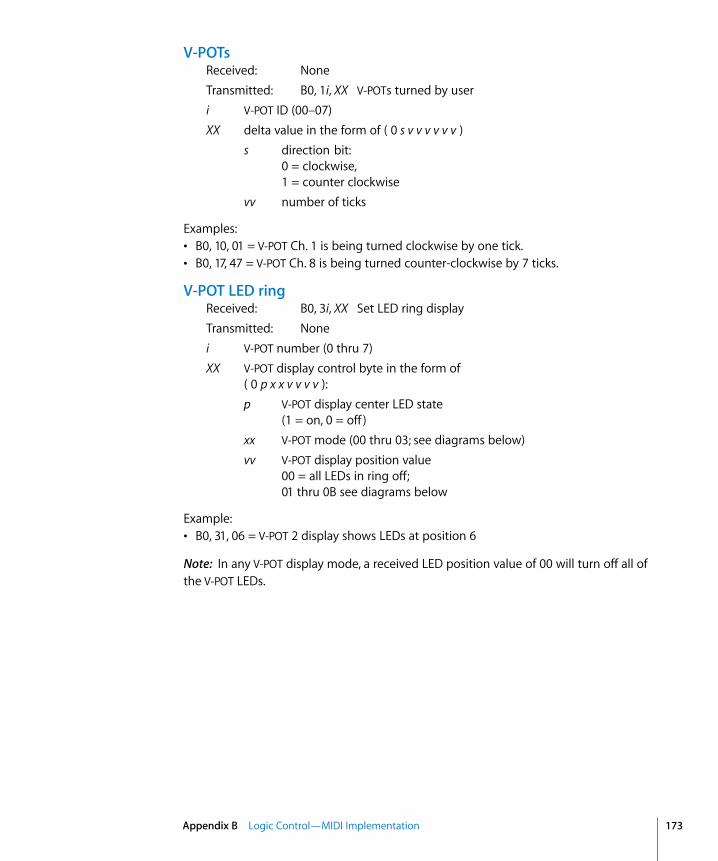
V-POTsReceived: NoneTransmitted: B0, 1i, XX V-POTs turned by useri V-POT ID (00–07)XX delta value in the form of ( 0 s v v v v v v )
s direction bit: 0 = clockwise,1 = counter clockwise
vv number of ticks
Examples:• B0, 10, 01 = V-POT Ch. 1 is being turned clockwise by one tick.• B0, 17, 47 = V-POT Ch. 8 is being turned counter-clockwise by 7 ticks.
V-POT LED ringReceived: B0, 3i, XX Set LED ring displayTransmitted: Nonei V-POT number (0 thru 7)XX V-POT display control byte in the form of
( 0 p x x v v v v ):p V-POT display center LED state
(1 = on, 0 = off )xx V-POT mode (00 thru 03; see diagrams below)vv V-POT display position value
00 = all LEDs in ring off;01 thru 0B see diagrams below
Example:• B0, 31, 06 = V-POT 2 display shows LEDs at position 6
Note: In any V-POT display mode, a received LED position value of 00 will turn off all of the V-POT LEDs.
Appendix B Logic Control—MIDI Implementation 173
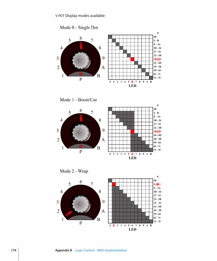
174
V-POT Display modes available:
Appendix B Logic Control—MIDI Implementation

External ControllerReceived: NoneTransmitted: B0, 2E, vv External Controller changedvv External Controller position value (00–7F)
Example:• B0, 2E, 07 = External Controller value = 07
Jog WheelReceived: NoneTransmitted: B0, 3C, XX Jog wheel turned by userXX delta value in the form of ( 0 s v v v v v v )s direction bit: 0 = clockwise, 1 = counter clockwisevv number of ticks
Examples:• B0, 3C, 01 = Jog forward• B0, 3C, 41 = Jog reverse
Appendix B Logic Control—MIDI Implementation 175

176
LCDReceived: <Hdr>, 12, oo, yy, …, F7 Update LCDTransmitted: Noneoo Display offset to write from:
00 thru 37 for upper line,38 thru 6F for lower line.
yy Data: ASCII equivalents for display characters written from left to right, including line wrapping between upper and lower line. Up to 100 data bytes may be sent in one message.
Example:• The following message writes “Hello” to top left of the LCD on a Logic Control master
section.F0 00 00 66 10 12 00 48 65 6C 6C 6F F7
Notes:• There are 7 displayed characters per channel, with the exception of channel 8, which
displays only the first 6 characters. Internally however, the LCD stores 2 x 56 characters.
• In most cases you will use the LCD in a scribble-strip fashion (text above each channel). In this case, you should use only the first six characters per channel to leave space between channel text.
• The lower line can be switched into meter mode. See Metering section on page 179 for further details.
• While the LCD switches between horizontal and vertical metering mode, it ignores LCD messages. After you sent an LCD metering mode change message, you should delay LCD messages for at least 600 ms.
Appendix B Logic Control—MIDI Implementation

Time Code/BBT DisplayReceived:
<Hdr>, 10, yy, …, F7 Update multiple charactersB0, 4i, yy Update single character
Transmitted: Nonei Digit ID: 0 = right-most, 9 = left-mostyy Data bytes representing character to be written (See 7-Segment Display Char-
acter Table section on page 178). Up to ten characters can be sent in the SysEx message.
Examples:• The following message writes “109.02.01.126” to the Time Code display (note decimal
points)F0 00 00 66 10 10 36 32 31 71 30 72 30 79 30 31 F7
• B0 40 30 41 31 = writes “10” into the last two digits.
Important: The digits in the Time Code display and Assignment display are written RIGHT-TO-LEFT to help conserve bandwidth.
Assignment 7-segment displayReceived:
<Hdr>, 11, yy, yy, F7 Update multiple charactersB0, 4i, yy Update single character
Transmitted: Nonei Digit ID: A= right, B = leftyy Data bytes representing character to be written (See 7-Segment Display Char-
acter Table section on page 178). Two characters can be sent in the SysEx message
Example:• B0 4B 10 4A 4E = writes “Pn.” to the Assignment display
Important: The digits in the Time Code display and Assignment display are written RIGHT-TO-LEFT to help conserve bandwidth.
Appendix B Logic Control—MIDI Implementation 177

178
7-Segment Display Character Table
Hint:• Characters @ (40h) thru ` (60h) = (ASCII value) − 40h• Characters ! (21h) thru ? (3Fh) = ASCII value
Note: The decimal point on each 7-segment character can be lit by adding 40 Hex to the value of the data.
Appendix B Logic Control—MIDI Implementation

MeteringReceived:
D0, XX Peak level<Hdr>, 20, ii, mm, F7 Channel meter mode<Hdr>, 21, yy, F7 Global LCD meter mode
Transmitted: NoneXX Meter level in the form of ( 0 h h h l l l l ):
hh Channel to be addressed (0 thru 7)ll Meter level:
0 thru C = level meter 0% to 100%Overload not cleared!
E = set overloadF = clear overload
ii Channel ID (0 to 7)mm mode bit map in the form of ( 0 0 0 0 0 l p s ):
l Enable level meter on LCDp Enable peak hold display (horizontal only)s Enable Signal LED
yy 00 = horizontal; 01 = vertical
Notes:• There is only one level meter per channel. For stereo tracks, use the maximum of left
and right levels.• Only transmit peak levels. Logic Control automatically decreases the level meter bars,
and switches off the Signal Present LED with time. This way, MIDI bandwidth takes up only a fraction compared to implementations where the current level (and peak level) has to be transmitted constantly.
• Decay rate is approximately 300ms per meter division (1.8 seconds to fall from 100% to 0%)
• The LCD meter value and the duration of the Signal Present LED are controlled by the same data byte.
• While the LCD switches between horizontal and vertical metering mode, it ignores LCD messages. After you sent an LCD metering mode change message, you should delay LCD messages for at least 600 ms.
Appendix B Logic Control—MIDI Implementation 179


App
endi
x
C
C Logic Control—Control Surface Layout and IDsID Switch LED Function
00 • • REC/RDY Ch. 1
01 • • REC/RDY Ch. 2
02 • • REC/RDY Ch. 3
03 • • REC/RDY Ch. 4
04 • • REC/RDY Ch. 5
05 • • REC/RDY Ch. 6
06 • • REC/RDY Ch. 7
07 • • REC/RDY Ch. 8
08 • • SOLO Ch. 1
09 • • SOLO Ch. 2
0A • • SOLO Ch. 3
0B • • SOLO Ch. 4
0C • • SOLO Ch. 5
0D • • SOLO Ch. 6
0E • • SOLO Ch. 7
0F • • SOLO Ch. 8
10 • • MUTE Ch. 1
11 • • MUTE Ch. 2
12 • • MUTE Ch. 3
13 • • MUTE Ch. 4
14 • • MUTE Ch. 5
15 • • MUTE Ch. 6
16 • • MUTE Ch. 7
17 • • MUTE Ch. 8
18 • • SELECT Ch. 1
19 • • SELECT Ch. 2
181

182
1A • • SELECT Ch. 3
1B • • SELECT Ch. 4
1C • • SELECT Ch. 5
1D • • SELECT Ch. 6
1E • • SELECT Ch. 7
1F • • SELECT Ch. 8
20 • V-Select Ch. 1
21 • V-Select Ch. 2
22 • V-Select Ch. 3
23 • V-Select Ch. 4
24 • V-Select Ch. 5
25 • V-Select Ch. 6
26 • V-Select Ch. 7
27 • V-Select Ch. 8
28 • • ASSIGNMENT: TRACK
29 • • ASSIGNMENT: SEND
2A • • ASSIGNMENT: PAN/SURROUND
2B • • ASSIGNMENT: PLUG-IN
2C • • ASSIGNMENT: EQ
2D • • ASSIGNMENT: INSTRUMENT
2E • FADER BANKS: BANK Left
2F • FADER BANKS: BANK Right
30 • FADER BANKS: CHANNEL Left
31 • FADER BANKS: CHANNEL Right
32 • • FLIP
33 • • GLOBAL VIEW
34 • NAME/VALUE
35 • SMPTE/BEATS
36 • F1
37 • F2
38 • F3
39 • F4
3A • F5
3B • F6
3C • F7
3D • F8
ID Switch LED Function
Appendix C Logic Control—Control Surface Layout and IDs

3E • GLOBAL VIEW: MIDI TRACKS
3F • GLOBAL VIEW: INPUTS
40 • GLOBAL VIEW: AUDIO TRACKS
41 • GLOBAL VIEW: AUDIO INSTRUMENT
42 • GLOBAL VIEW: AUX
43 • GLOBAL VIEW: BUSSES
44 • GLOBAL VIEW: OUTPUTS
45 • GLOBAL VIEW: USER
46 • SHIFT
47 • OPTION
48 • CONTROL
49 • CMD/ALT
4A • • AUTOMATION: READ/OFF
4B • • AUTOMATION: WRITE
4C • • AUTOMATION: TRIM
4D • • AUTOMATION: TOUCH
4E • • AUTOMATION: LATCH
4F • • GROUP
50 • • UTILITIES: SAVE
51 • • UTILITIES: UNDO
52 • UTILITIES: CANCEL
53 • UTILITIES: ENTER
54 • • MARKER
55 • • NUDGE
56 • • CYCLE
57 • • DROP
58 • • REPLACE
59 • • CLICK
5A • • SOLO
5B • • REWIND
5C • • FAST FWD
5D • • STOP
5E • • PLAY
5F • • RECORD
60 • Cursor Up
61 • Cursor Down
ID Switch LED Function
Appendix C Logic Control—Control Surface Layout and IDs 183

184
62 • Cursor Left
63 • Cursor Right
64 • • Zoom
65 • • Scrub
66 • User Switch A
67 • User Switch B
68 • Fader Touch Ch. 1
69 • Fader Touch Ch. 2
6A • Fader Touch Ch. 3
6B • Fader Touch Ch. 4
6C • Fader Touch Ch. 5
6D • Fader Touch Ch. 6
6E • Fader Touch Ch. 7
6F • Fader Touch Ch. 8
70 • Fader Touch Master
71 • SMPTE LED
72 • BEATS LED
73 • RUDE SOLO LIGHT
76 • Relay click
ID Switch LED Function
Appendix C Logic Control—Control Surface Layout and IDs

App
endi
x
D
D Logic Control—MIDI Implementation ChartMode 1: OMNI ON, POLY, Mode 2: OMNI ON, MONO, O: YesMode 3: OMNI OFF, POLY, Mode 4: OMNI OFF, MONO, X: No
Function Transmitted Recognized Remarks
Channel, Default:Changed:
11
11
Each Logic Control unit should be installed on a separate MIDI port.
Mode, Default:Messages:Altered:
XXX
XXX
Note NumberTrue Voice:
O 0–127X
O 0–127X
Velocity, Note On:Note Off:
O v = 1–127X v = 00
O v = 1–127X v = 00
After Touch, Keys:Chan‘s:
XX
XO
Pitch Bend O O used for motor faders
Control Change O O
Program ChangeTrue #:
X X
SYSTEM EXCLUSIVE:
O O
SYSTEM COMMON:
X X
185


Inde
x
Index
AAbbreviation 22ABORT/UNDO 112About 16Alert Messages 23ALL SAFE 86ALT 93ALT/CMD 86AMT 8 14Arrange window 93, 96, 104, 109, 118, 133arrow tool 99, 114ASSIGN 92, 95, 121, 134ASSIGN 1 109ASSIGN 2 109ASSIGN 3 109Assignment LED 22ASSIGN section 92* 99Audio Instruments 96, 99, 114Audio Pool window 93, 113, 122, 136Audio Tracks 96, 99, 114Audio window 96AUDITION 100, 114AUTO 94, 97, 115, 122, 129AUTO ENABLE section 96Autoload Song 24Automation 53automation mode 94, 97, 104, 112, 115, 118, 122, 124, 129, 132, 135, 138automation playback 96, 104, 129Automation Section 104AUTOMIX 118, 132AUTOMIX section 112AUTO MODE section 97AUTOREC 112AUX 86, 119AUX/MTRX 109, 126AUX 122, 135FADER MODE 135AUX SELECT section 108, 119, 126Aux Tracks 96, 99, 114
BDISPLAY HISTORY 115BANK buttons 88Bank LEDs 88Bank Left 93Bank Right 93BANK SELECT Left 105BANK SELECT Right 105bars/beats/format/ticks 96, 98, 111, 120, 128, 133BEATS 98, 111, 120, 128, 133Busses 96, 99, 114BYPASS 92, 95, 121, 134bypass 94, 110, 115, 121, 127, 134BYPASS/OFF 104
CCancel 19, 55cancel 96CAPTURE 98CHANNEL INSERTS 127, 129Channel Left 93Channel Right 93Channel strip display 115Channel strips 94, 103, 115, 122, 129, 135Channel Strip View 20, 32Channel Strip view 33Channel Views 20Click 61CLR 99CLR SOLO 86Cmd/ALT 29Cmd/Alt 53CMD/ALT/FINE 93COMPARE 95, 121, 134Compatibility 44computer keyboard 99Control 53COPY 86, 98CREATE 97CTRL 86CTRL/CLUTCH 93Cursor buttons 88, 101
187

188
Cursor Down 101, 116, 130Cursor Keys 64Cursor Left 101, 116, 130Cursor Right 101, 116, 130Cursor Up 101, 116, 130CUT 86, 98Cycle 59, 100
DData Entry section 121, 135DAW ALT/FINE 123, 136DAW AUTO FADER 124, 137DAW AUTO LATCH 124, 137DAW AUTO MUTE 124, 137DAW AUTO OFF 124, 138DAW AUTO PAN 124, 137DAW AUTO PLUGIN 124, 137DAW AUTO READ 124, 137DAW AUTO SEND 124, 137DAW AUTO SEND MUTE 124, 137DAW AUTO STATUS 124, 138DAW AUTO TOUCH 124, 137DAW AUTO TRIM 124, 138DAW AUTO WRITE 124, 137DAW BANK- 122, 136DAW BANK+ 122, 136DAW CHANNEL - 123, 136DAW CHANNEL+ 123, 136DAW CREATE GROUP 123, 136DAW CTRL/CLUTCH 123, 136DAW EDIT TOOL 123, 137DAW END 124, 137DAW FF 123, 137DAW GROUP STATUS 123, 136DAW IN 124, 137DAW MONI STATUS 123, 136DAW ONLINE 124, 137DAW OPTION/ALL 122, 136DAW OUT 124, 137DAW PLAY 123, 137DAW POST 124, 137DAW PRE 124, 137DAW QUICK PUNCH 124, 137DAW REC 123, 137DAW REC/RDY 122, 136DAW REC/RDY ALL 123, 137DAW REW 123, 137DAW RTZ 124, 137DAW SAVE 123, 136DAW SCRUB 123, 137DAW SHIFT/ADD 122, 136DAW SHUTTLE 123, 137DAW STOP 123, 137DAW SUSPEND 123, 136DAW UNDO 123, 136
DAW WIN INSERT 123, 137DAW WIN MEM-LOC 123, 136DAW WIN MIX/EDIT 123, 136DAW WIN STATUS 122, 136DAW WIN TRANSPORT 122, 136DEC 116, 130DEFAULT 92default 108, 119, 127, 132DEL 86DELETE 98dialog 96DISPLAY 112, 113, 114, 118, 129, 130, 132Display 110, 127DISPLAY ACCESS section 109, 118, 126, 132DISPLAY HISTORY 114Display Section 104Drop 60, 100, 114, 124, 137Drop In locator 100, 105, 114, 124, 137Drop Out locator 100, 105, 114, 124, 137DSP display 110, 121, 127, 134DSP EDIT/ASSIGN section 95DSP Select 95, 110, 121, 127, 134DSP V-Pot 95, 110, 121, 127, 134
EEDIT 93, 104EDIT MODE 93EDIT section 98EDIT TOOL 93, 99EEPROM 16EFFECT 118, 132EFFECTS/PLUG-INS 129EFFECTS/PLUG-INS section 110, 127enables Inputs 96Encoder 87, 115, 122, 129, 134, 135Encoder Assignment Section 104ENCODER MODE 92, 115ENCODER MODE section 109, 119, 126Encoder Push-Switch 115, 122, 129, 134ENCODERS 86Encoder Switch 134END 100, 105, 114ENTER 99, 116, 130Enter 19, 56EQ 37, 87equalizer 37= 99Event Editor window 96Extended Track View 19, 97, 113, 123, 136
FF1 96F10 88F2 96F3 96
Index

F4 96F5 96F6 96F7 88, 96F8 88F8/ESC 96F9 88FADER 96, 109, 126Fader 87, 94, 103, 115, 122, 129, 135FADER BANK 20Fader Bank 46Fader bank buttons 93FADER MODE 119FADER MODE section 109, 119, 126, 132FAST FWD 100, 105Fast Fwd 62FEET 98, 111, 120, 128, 133FF 115, 130FFWD 89fine 93, 113, 123, 136Firmware 16FLIP 86Flip Mode 47Flip mode 92, 109, 119, 126, 133folder 96, 99, 116, 121, 130, 135Folders 19Follow Control Surface 19Footswitch 15Foot Switch 1 101Foot Switch 2 101Foot switches 101DISPLAY HISTORY 115FREQ 87full 93, 113, 122, 136Function Keys 51Function keys 96
GGAIN 87Global View 18, 96, 97, 109, 113, 118, 123, 133, 136glue tool 99, 114Goto Marker 99GROUP 97Group 54, 97, 113, 118, 123, 132, 136Group Clutch 93, 97, 113, 123, 129, 136group membership 97
HHIGH 87HI-MID 87HOME 133Hyper Editor window 96
IIN 88, 100, 114
INC 116, 130Individual track zoom 101, 116INPUT 92Inputs 99, 114INSERT 94INSERT/PARAM 95, 121, 134Insert Bypass 92, 108Insert Select 92, 108Instrument 45
JJog/Scrub 65Jog wheel 101
KKEYBOARD SHORTCUTS section 93
LLarge Marker Mode 57Large Nudge Mode 58LATCH 88, 97Latch 53, 97, 112, 124, 137LCD 111, 120, 128, 133LCD Channel page 134LCD Function 120, 133LCD Insert page 121, 134left locator 100, 114, 124, 137level 94, 115, 122, 135Level Meters 94, 115, 122, 135LOCATE 88LOCATE/NUMBERS section 99LOCATOR section 114LOOP 86, 100LOW 87LOW-MID 87
MMACHINE CONTROL section 130Marker 25, 57marker 99Marker List window 93, 104, 114, 123, 130, 136MARKERS 86MASTER 111MASTER fader 88Master Fader 48Matrix Editor window 96MATRIX SELECT section 108MEM-LOC 93, 104METER 109, 118, 126Metronome 61MIDI interface 14MIDI Tracks 96, 99, 109, 114, 118, 133– 99– (DEC) 121, 135MIX 93, 104
Index 189

190
MODE 101Modifier 52MONITOR 97Motor Fader 31Multi Channel View 20, 32Multi Channel view 33MUTE 87, 92, 94, 96, 103Mute 20, 30, 94, 96, 103, 104, 115, 122, 129, 135mute tool 99, 114
NName/Value 21, 22, 49Navigation section 105next tool 93NUDGE 88Nudge 58
OOFF 97Off 97, 104, 112, 124, 129, 138ON 115, 122, 129, 1351 99ON LINE 100ONLINE 114OPTION 29Option 52OPTION/ALL 93OUT 89, 100, 114OUTPUT 92Outputs and Master object 96, 99, 114Overload LEDs 96, 109, 118, 126, 133
PPage Down 101, 116Page Left 101, 116Page Right 101, 116Page Up 116PAIR/GROUP 118, 132PAN 86, 92, 96, 104, 109, 119, 126Pan 35, 92, 96, 104, 129Pan/Surround 35Pan Encoder 135parameter display 95, 110, 120, 127, 133Parameter Wheel 116, 121, 130, 135PASTE 86, 98Pause 65, 100, 115, 123, 137pedals 15pencil tool 99, 114PHASE 97PLAY 89, 100, 105, 115, 130Play 63PLUG IN 96Plug-in 42Plug-in parameters 96, 129PLUG-INS 127
+ 99+ (INC) 121, 135. 99POST 100, 114Power Supply Unit 15PRE 100, 114PSU 15
QQ 87QUICK PUNCH 100, 114Quick Start 17
RREAD 88, 97, 104Read 97, 104, 112, 124, 137Read/Off 53REC 87, 89, 112, 115, 130REC/RDY 94REC/RDY ALL 92REC LEDs 87RECORD 100, 105Record 63Record/Ready 29Record Ready 92, 94, 103, 111, 122, 136redo 93, 113, 123, 136RELATIVE 112Replace 61Requirements 91, 103, 107, 117, 125, 131RETURN 112RETURN TO ZERO 114REVERT 86REW 89, 115, 130REWIND 100, 105Rewind 62right locator 100, 114, 124, 137Rotary encoder 103Rotary encoder push button 103RTZ 100, 105rubber tool 99, 114RUDE SOLO LIGHT 98
SSample Editor window 93SAVE 86, 93Save 55, 113, 123, 136Save As 93, 113, 123, 136scissors tool 99, 114Score Editor window 96Screen Set 96Scribble Strip 94SCROLL 95Scroll to bottom 101, 116Scroll to left border 101, 116Scroll to right border 116
Index

Scroll to top 101, 116SCRUB 101, 115, 130Scrub 65, 115, 123, 130, 137SEL 87, 115, 122, 129, 135SELECT 94Select 30SELECT-ASSIGN 92, 111, 120, 128, 133Selected Channel 135SEND 96Send 39, 86SEND 1 104Send 1 Level 92, 104, 108, 119, 126, 132SEND 2 104Send 2 Level 92, 104, 108, 119, 126, 132SEND 3 104Send 3 Level 92, 104, 108, 119, 126, 132SEND 4 104Send 4 Level 92, 104, 108, 119, 126, 132Send 5 Level 92, 108, 119, 126, 132SEND A 92SEND B 92SEND C 92Send Channel Strip 2 View 40SEND D 92Send Destination 92, 109SEND E 92Send Level 96, 104, 129SEND MUTE 96Send Mute 92, 108Send Position 92, 108Send Pre/Post 94SEPARATE 98SET 88Set up 91, 103, 125SHIFT 86, 92, 104Shift 52SHIFT/ADD 93SHORTCUTS 86Shortcuts 34SHTL 88SHUTTLE 101, 116, 130Shuttle 100, 105, 115, 116, 123, 130, 137Signal LED 29/ 99Small Marker Mode 56Small Nudge Mode 58SMPTE 96SMPTE/Beats 23, 50SMPTE Time Display 23SOLO 87, 94, 103, 115, 122, 129, 135Solo 20, 29, 61, 94, 103, 115, 122, 129, 135Solo LED 23solo tool 99, 114Specifications 165STATUS 93STATUS/GROUP section 97
Stereo Channel strip 122, 135STOP 89, 100, 105, 115, 130Stop 63Surround 35Surround Angle 95, 110, 121, 127, 134Surround Diversity 95, 110, 121, 127, 134Surround LFE 95, 110, 121, 127, 134Surround Mode 95, 110, 121, 127, 134SUSPEND 92, 97Swap Mode 47Sync 100, 114, 124, 137
TTCH 88Temporary Marker Mode 57Temporary Nudge Mode 59text edit tool 99, 114TIME CODE 98, 111, 120, 128, 133Time display 98, 111, 120, 128, 133tool 115, 123, 137TOUCH 97, 104Touch 53, 97, 104, 112, 124, 129, 137TOUCH SENSE 112Track 33TRACK ARMING section 111Track Input 92, 109Track Mixer 19Track Mixer window 93, 96, 104, 113, 123, 129, 136Track Output 92, 109Track View 18, 97, 113, 118, 123, 132, 136TRANSPORT 93, 104Transport/cursor section 115Transport section 100, 105Transport window 93, 96, 104, 113, 122, 136Transport Zone 56TRIM 97Trim 53
UU 101UNDO 86, 93, 104Undo 55undo 113, 123, 136undo history window 93, 113, 123, 136Unitor 8 14unity level 94, 115, 122, 135USER DEFINED KEYS section 113, 122, 129, 136USER switch A 15USER switch B 15Utilities 55Utility Section 104
VView modes 17Volume 96, 104, 129
Index 191

192
V-Pot 28, 32, 94V-SEL 94V-SELECT 28V-Select 32
WWheel 88WINDOW section 93WRITE 88, 97, 104Write 53, 97, 104, 112, 124, 129, 137
XXSKey 91, 103, 107, 117, 125, 131, 147
Z0 99Zero Mode 47Zoom 101, 116Zoom Key 64Zoom mode 101, 130zoom tool 99
Index