Locking Attachment Plate. For treatment of periprosthetic ...synthes.vo.llnwd.net/o16/LLNWMB8/INT...
32
Locking Attachment Plate. For treatment of periprosthetic fractures. Surgical Technique This publication is not intended for distribution in the USA. Instruments and implants approved by the AO Foundation.
Transcript of Locking Attachment Plate. For treatment of periprosthetic ...synthes.vo.llnwd.net/o16/LLNWMB8/INT...

Locking Attachment Plate. For treatment of periprosthetic fractures.
Surgical Technique
This publication is not intended for distribution in the USA.
Instruments and implants approved by the AO Foundation.


Locking Attachment Plate Surgical Technique DePuy Synthes 1
Introduction
Surgical Technique
Product Information
Bibliography 24
MRI Information 25
Table of Contents
Locking Attachment Plate 2
Indications 4
Preparation 5
Patient Positioning and Approach 6
Surgical Steps 8
Implant removal 19
Locking Attachment Plates 3.5 20
Screws 21
Instruments 22
Sets 23
Image intensifier control
WarningThis description alone does not provide sufficient background for direct use of DePuy Synthes products. Instruction by a surgeon experienced in handling these products is highly recommended.
Processing, Reprocessing, Care and MaintenanceFor general guidelines, function control and dismantling of multi-part instruments, as well as processing guidelines for implants, please contact your local sales representative or refer to:http://emea.depuysynthes.com/hcp/reprocessing-care-maintenanceFor general information about reprocessing, care and maintenance of Synthes reusable devices, instrument trays and cases, as well as processing of Synthes non-sterile implants, please consult the Important Information leaflet (SE_023827) or refer to: http://emea.depuysynthes.com/hcp/reprocessing-care-maintenance

2 DePuy Synthes Locking Attachment Plate Surgical Technique
Locking Attachment Plate. For treatment of periprosthetic fractures.
Overview
DescriptionThe Locking Attachment Plate is part of the Synthes Large and Small Fragment LCP System. The main indication of the Locking Attachment Plate is the treatment of periprosthetic fractures. Other indications are prevention of lateral screw pull-out in osteoporotic bone and fractures around in-tramedullary implants. It is an alternative to cables and can be used with different Locking Compression Plates 4.5/5.0.
The arms on each side of the plate offer the possibility to avoid the prosthesis stem with 3.5 mm locking screws (or 3.5 mm cortex screws). The locking capability is important for a fixed-angle construct in osteopenic bone, periprosthetic fractures or multifragment fractures where screw purchase is compromised. These screws do not rely on plate-to-bone compression to resist patient load, but function similarly to multiple, small angled blade plates.
Note: LCP 4.5/5.0 also applies to VA-LCP 4.5/5.0
The Locking Attachment Plates for LCP ProximalFemoral Plates fit on the following plates: – LCP Proximal Femoral Plate 4.5 /5.0 – LCP Proximal Femoral Hook Plate 4.5/5.0
The Locking Attachment Plates for LCP 4.5/5.0 fit on the following plates: – LCP DF 4.5/5.0 – VA-LCP 4.5/5.0 Condylar Plate – LCP Condylar Plate 4.5/5.0 – LCP 4.5/5.0 broad and broad, curved – VA-LCP Condylar Plate 4.5/5.0

Locking Attachment Plate Surgical Technique DePuy Synthes 3
Features and benefits
– Anatomically contoured to fit on the femoral shaft – One plate version available to fit on Large Fragment LCP
plates. A second version available for LCP Proximal Femoral Plates
– Crossed arms on each side of the plate for 3.5 mm locking screws (and 3.5 mm cortex screws), which offer the possibility to avoid the prosthesis stem
– Creates a fixed angled construct and improves fixation with the use of 3.5 mm locking screws
– Arms can be bent and cut to fit well on the femoral shaft – Hole for connection screw to connect the Locking
Attachment Plate to the LCP Plate – Good mechanical stability – Simple and established LCP technique – Compatible with large and small fragment LCP
instrumentation – Available guiding blocks guide the drill sleeves while
providing easy handling
Note: More detailed information on conventional and locked plating principles can be found in the Surgical Technique LCP Locking Compression Plate (Art. No. 036.000.019) and in the AO Manual of Fracture Management – Internal Fixators by M. Wagner and R. Frigg.1
1 M. Wagner, R. Frigg, AO Manual of Fracture Management – Internal Fixators, Thieme, Stuttgart, New York, 2006
4 holes
8 holes
4 holes
8 holes

4 DePuy Synthes Locking Attachment Plate Surgical Technique
Indications
– Periprosthetic femoral shaft fractures: – Vancouver B – Vancouver C – Fractures around intramedullary implants
Precaution: In case of a completely loose prosthesis, a revi-sion prosthesis is needed.
Vancouver C
Vancouver B

Locking Attachment Plate Surgical Technique DePuy Synthes 5
1Preparation
Required sets
01.120.457 Large Fragment LCP Instrument Set and Standard Instrument Set in Vario Case
01.120.140–155 Locking Screws B 3.5 mm, in Vario Case
01.120.100–130 Locking Attachment Plate Set
Instruments
01.120.101/111 Instrument Set for Locking Attachment Plates
511.701 Compact Air Drive or 530.100 Power Drive
511.790 Quick Coupling for Kirschner Wires
Optional sets
3.5 mm Cortex Screw Set
181.500 Collinear Reduction Forceps
Additional reduction tools
Complete a preoperative radiographic assessment and pre-pare the preoperative plan. Position the patient supine on a radiolucent operating table. Viewing the femoral shaft under fluoroscopy in both the lateral and AP views is neces-sary when using a minimally invasive plating technique.
Preparation

6 DePuy Synthes Locking Attachment Plate Surgical Technique
Patient Positioning and Approach
1Position the patient
Position the patient supine on a radiolucent table. The leg should be freely movable. The contralateral leg can be placed in an obstetric leg holder. Place the knee joint line slightly distal to the hinged part of the table to allow flexion of the knee during surgery.
2Approach
Cut a straight incision, or two to three small incisions, on the lateral side of the thigh depending on the reduction and plate insertion technique.

Locking Attachment Plate Surgical Technique DePuy Synthes 7
3Reduce fracture
Reduce and temporarily secure the fragments (e.g.: with collinear reduction forceps or cerclage).

8 DePuy Synthes Locking Attachment Plate Surgical Technique
Surgical Steps
1Choose and insert LCP
Choose an LCP Plate of adequate length which sufficiently bridges the fracture, e.g.: LCP DF 4.5/5.0, LCP 4.5/5.0 broad curved or LCP 4.5/5.0 Proximal Femoral (Hook) Plate.
In cases of osteoporotic bone, it is recommended to place bicortical screws distally to the prosthesis stem and mono-cortical periprosthetic screws in the area of the prosthesis stem. Alternatively, insert angulated cortex screws in the area of the prosthesis stem.
Alternative Implant: Additionally to LCP Plates the Locking Attachment Plate can also be combined with a VA-LCP Plate.
Please consult the following Surgical Techniques for detailed information on conventional and locked plating principles, as well as required instruments: – VA-LCP Condylar Plate (Art. No. 036.001.365) – LCP Looking Compression Plate (Art. No. 036.000.019) – LISS DF (Art. No. 036.000.235) – LCP Condylar Plate (Art. No. 036.000.727) – LCP Proximal Femoral Plate 4.5/5.0 (Art. No. 036.000.403) – LCP Proximal Femoral Hook Plate 4.5/5.0
(Art. No. 036.000.863).
Note: There should be no screws already inserted in the combi-holes where the Locking Attachment Plate is to be connected to the LCP. These holes will be needed for the connection screws.

Locking Attachment Plate Surgical Technique DePuy Synthes 9
4 holes 8 holes Fit on LCP and VA-LCP Plates
Locking Attachment Plate 3.5, for LCP 4.5/5.0 RMarking: A
– LCP 4.5/5.0 broad – LCP 4.5/5.0 broad, curved – LCP DF 4.5/5.0 and
LISS DF 5.0 – LCP Condylar Plate 4.5/5.0 – VA-LCP Condylar Plate 4.5/5.0
Locking Attachment Plate 3.5, for LCP Proximal Femoral Plates RMarking: B
– LCP Proximal Femoral Plate 4.5/5.0
– LCP Proximal Femoral Hook Plate 4.5/5.0
2Choose the appropriate Locking Attachment Plate
The Locking Attachment Plate for LCP 4.5/5.0 is used with LISS/LCP DF, LCP Condylar Plate 4.5/5.0, LCP 4.5/5.0 broad and broad curved and VA-LCP Condylar Plate 4.5/5.0
The Locking Attachment Plate for LCP Proximal Femoral Plates, with its slightly rounded shape is used with LCP Proxi-mal Femoral (Hook) Plates. They are marked with the letters A and B.

10 DePuy Synthes Locking Attachment Plate Surgical Technique
Surgical Steps
3Optional: bend the Locking Attachment Plate
Instruments
329.916 Bending Pin for LCP Plates 3.5, with thread
329.151 Cutting Pliers with Positioning Pin B 3.0 mm
If required, the four outer holes of the Locking Attachment Plate can be pre-bent manually with the bending pins.
Screw the threaded bending pin into one of the outer holes of the locking attachment plate. Use the bending pin as a joystick to manually bend the arm of the plate.
Notes – The arms of the 8 hole Locking Attachment Plate can be
cut with the cutting pliers if they are too long. – The guiding block can only be used if the plate is not
manually pre-bent.

Locking Attachment Plate Surgical Technique DePuy Synthes 11
upper part
conical part
4Insert the conical part of the connection screw
Instruments
324.052 Torque-limiting Screwdriver 3.5or314.163 Torque-limiting Screwdriver Stardrive, T25
The connection screw consists of two parts (see picture). After having decided where to attach the Locking Attach-ment Plate, screw the conical part of the connection screw into the locking part of the LCP combi-hole with the torque- limiting screwdriver (large fragment). After one click, opti-mum torque is reached.

1
2
12 DePuy Synthes Locking Attachment Plate Surgical Technique
Surgical Steps
5Optional: fix the guiding block onto the Locking Attachment Plate
Instruments
03.120.044 or Guiding Block for Locking Attachment Plate 3.5 for LCP 4.5/5.0
R marking: A
03.120.045 Guiding Block for Locking Attachment Plate 3.5 for LCP Proximal Femoral Plates
R marking: B
03.120.043 Centering Sleeve 8.0/5.0, for Guiding Block for Locking Attachment Plate
03.120.040 LCP Drill Sleeve 3.5, for Drill Bits B 2.8 mm (03.120.041), length 108 mm
Fix the appropriate guiding block onto the Locking Attach-ment Plate by pressing it down upon the plate until a click is heard. Make sure that the marking on the guiding block is the same as the one on the Locking Attachment Plate (letters A or B).
Slide the 3.5 LCP drill sleeve into the 8.0/5.0 centering sleeves for optimal guidance.
After having screwed the centering sleeves into the guiding block (1), screw the LCP drill sleeves into the locking hole (2).
If needed, bend the outer holes with the bending pin after the fixation of the guiding block.
Locking Attachment Plate Surgical Technique DePuy Synthes 13
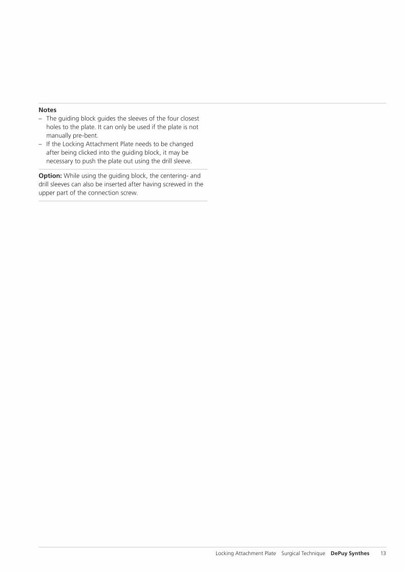
Notes – The guiding block guides the sleeves of the four closest
holes to the plate. It can only be used if the plate is not manually pre-bent.
– If the Locking Attachment Plate needs to be changed after being clicked into the guiding block, it may be necessary to push the plate out using the drill sleeve.
Option: While using the guiding block, the centering- and drill sleeves can also be inserted after having screwed in the upper part of the connection screw.

14 DePuy Synthes Locking Attachment Plate Surgical Technique
Surgical Steps
6Connect the Locking Attachment Plate to the LCP (with or without guiding block)
Instruments
03.120.040 LCP Drill Sleeve 3.5, for Drill Bits B 2.8 mm (03.120.041), length 108 mm
511.115 Torque Limiter, 1.5 Nmor511.773 Torque Limiter, 1.5 Nm
314.550 Screwdriver Shaft, hexagonalor03.100.045 Screwdriver Shaft T15, self-holding
311.431 Handle with Quick Coupling
In cases where no guiding block is used, screw in the drill sleeves to use them as handles.
Position the Locking Attachment Plate correctly onto the LCP in the area of the prosthesis stem. The hole for the con-nection screw must lie directly above the threaded part of the combi-hole of the LCP, where the conical part of the connection screw is already screwed in.
To fix the Locking Attachment Plate to the LCP, screw the upper part of the connection screw into the threaded hole of the conical part using instrumentation for small fragment. After one click, the optimum torque is reached.
Check position under image intensification.
Locking Attachment Plate Surgical Technique DePuy Synthes 15
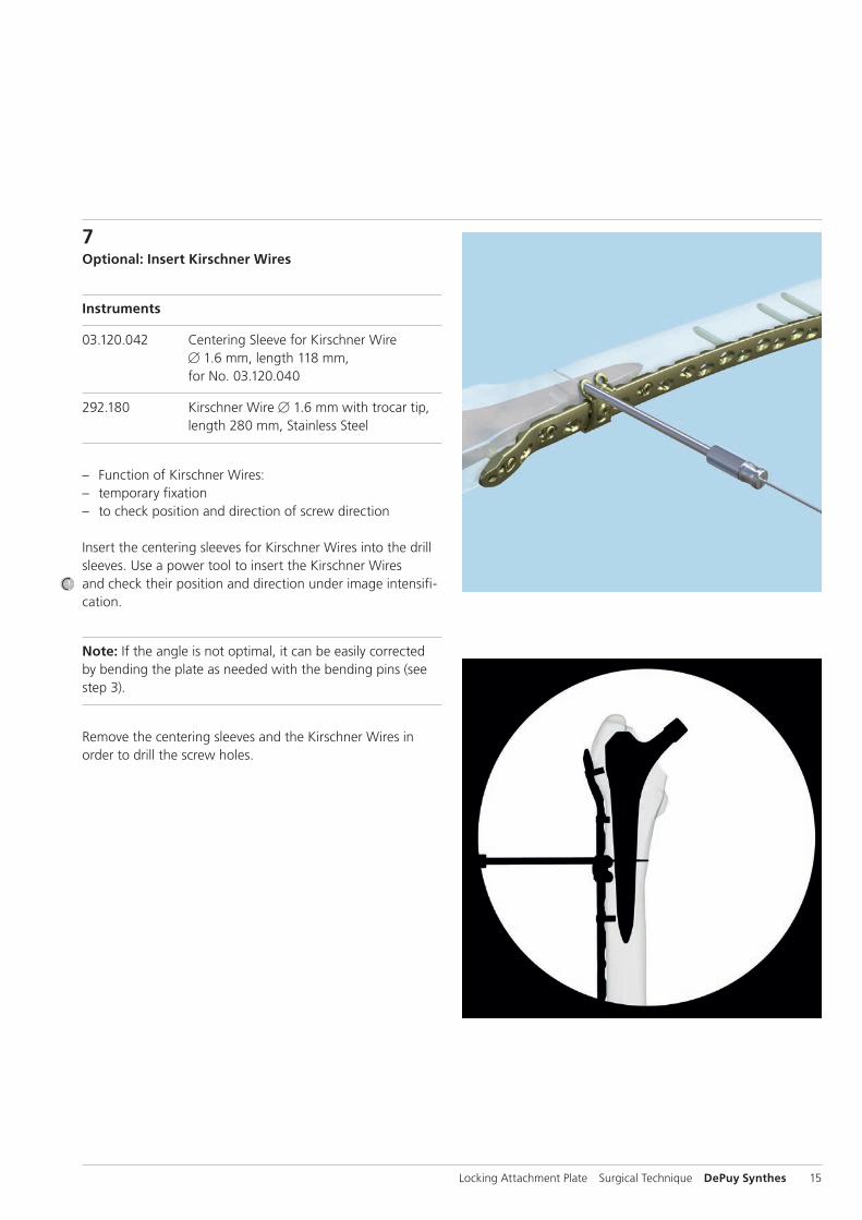
7Optional: Insert Kirschner Wires
Instruments
03.120.042 Centering Sleeve for Kirschner Wire B 1.6 mm, length 118 mm, for No. 03.120.040
292.180 Kirschner Wire B 1.6 mm with trocar tip, length 280 mm, Stainless Steel
– Function of Kirschner Wires: – temporary fixation – to check position and direction of screw direction
Insert the centering sleeves for Kirschner Wires into the drill sleeves. Use a power tool to insert the Kirschner Wires and check their position and direction under image intensifi-cation.
Note: If the angle is not optimal, it can be easily corrected by bending the plate as needed with the bending pins (see step 3).
Remove the centering sleeves and the Kirschner Wires in order to drill the screw holes.
16 DePuy Synthes Locking Attachment Plate Surgical Technique
Surgical Steps
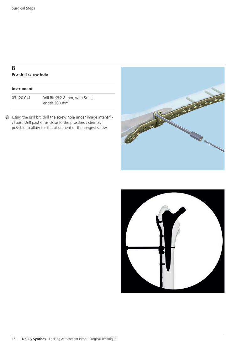
8Pre-drill screw hole
Instrument
03.120.041 Drill Bit B 2.8 mm, with Scale, length 200 mm
Using the drill bit, drill the screw hole under image intensifi-cation. Drill past or as close to the prosthesis stem as possible to allow for the placement of the longest screw.

Locking Attachment Plate Surgical Technique DePuy Synthes 17
9Determine screw length
a. Measurement with drill bit
Instrument
03.120.041 Drill Bit B 2.8 mm, with Scale, length 200 mm
For easier reading, slide the stop ring down until it reaches the drill sleeve. Read the drilled depth directly from the laser mark on the drill bit.
Remove the drill bit and the drill sleeve.
Note: Replacement stop rings can be ordered from a local Synthes representative.
b. Measurement with depth gauge
Instrument
03.120.049 Depth Gauge for 03.120.040
Measure the screw length through the drill sleeves with the depth gauge.
Note: If using the conventional small fragment depth gauge, remove the drill sleeves before measurement.

18 DePuy Synthes Locking Attachment Plate Surgical Technique
10Insert locking screw
Instruments
511.115 Torque Limiter, 1.5 Nm
314.550 Screwdriver Shaft, hexagonalor03.100.045 Screwdriver Shaft T15, self-holding
311.431 Handle with Quick Coupling
Optional instruments
314.570 Screwdriver 2.5, hexagonal or03.113.021 Screwdriver Stardrive 3.5, T15, length 270 mm
Choose a 3.5 mm locking screw according to the measured length.
Precaution: If the prosthesis becomes impinged during drilling, choose a 2 mm shorter screw than measured to prevent stripping of the thread in the bone and loss of screw anchoring.
To insert the locking screw using a power tool, fit the torque limiter to the power tool, then insert the screwdriver shaft into the torque limiter. Pick up the locking screw and insert it into the locking hole. Stop the power tool before locking.
Uncouple the power tool, mount the handle, and manually tighten the screw with the torque limiter. After one click, optimum torque is reached.
Notes – If the guiding block is used, insert the screw through the
8.0/5.0 centering sleeve. – If there is thick cortical bone or cement, the 1.5 Nm
torque limiter may not be strong enough. In this case the screw has to be inserted and tightened manually with the screwdriver, or the handle and the screwdriver shaft.
Surgical Steps

Locking Attachment Plate Surgical Technique DePuy Synthes 19
11Place additional locking screws
Place additional locking screws as described in the previous steps.
If used, remove the guiding block and the 8.0/5.0 centering sleeves after having inserted the appropriate number of 3.5 mm locking screws.
12Optional: Place cortical screws
It is possible to place 3.5 mm cortical screws, instead of 3.5 mm locking screws, into the 3.5 mm holes of the Lock-ing Attachment Plate.
For detailed instructions on how to place cortical screws, please consult the Locking Compression Plate Surgical Technique (Art. No. 036.000.019).
13Place additional Locking Attachment Plates
If required, place additional Locking Attachment Plates as described in the previous steps.
14Implant RemovalIn case the physician decides to remove the implants, im-plants can be removed by using general surgical instruments. In case of difficult removal circumstances, a Screw Extraction Set is available with corresponding instructions (036.000.917).

20 DePuy Synthes Locking Attachment Plate Surgical Technique
Locking Attachment Plates 3.5
For LCP DF 4.5/5.0 and LISS DF 5.0, LCP Condylar Plate 4.5/5.0, LCP 4.5/5.0 broad and broad, curved and VA-LCP Condylar Plate 4.5/5.0 (marking: A):
Stainless Steel Titanium Holes
02.120.601 04.120.601 4
02.120.602 04.120.602 8
For LCP Proximal Femoral Plate 4.5/5.0 and LCP Proximal Femoral Hook Plate 4.5/5.0 (marking: B):
Stainless Steel Titanium Holes
02.120.603 – 4
02.120.604 – 8
All plates are available sterile packed.For sterile implants add suffix “S” to article number.

Locking Attachment Plate Surgical Technique DePuy Synthes 21
Screws
Connection Screws for Locking Attachment PlateHex: 0X.120.605 Stardrive: 0X.120.606 – Connects the Locking Attachment Plate to the LCP
4.5/5.0 through the locking holes
Locking Screws 3.5, self-tappingHex: X13.010–X13.080Stardrive: X12.101–128Creates a locked, fixed-angle screw-plate construct – Threaded conical head – Fully threaded shaft – Self-tapping tip
Cortex Screws 3.5, self-tapping (X04.810–860) – Compresses the plate to the bone or creates axial
compression – Can be slightly angulated
All plates are available sterile packed.For sterile implants add suffix “S” to article number.
X = 2: stainless steelX = 4: TAN
22 DePuy Synthes Locking Attachment Plate Surgical Technique
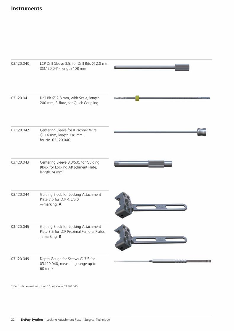
Instruments
03.120.040 LCP Drill Sleeve 3.5, for Drill Bits B 2.8 mm (03.120.041), length 108 mm
03.120.041 Drill Bit B 2.8 mm, with Scale, length 200 mm, 3-flute, for Quick Coupling
03.120.042 Centering Sleeve for Kirschner Wire B 1.6 mm, length 118 mm, for No. 03.120.040
03.120.043 Centering Sleeve 8.0/5.0, for Guiding Block for Locking Attachment Plate, length 74 mm
03.120.044 Guiding Block for Locking Attachment Plate 3.5 for LCP 4.5/5.0 Rmarking: A
03.120.045 Guiding Block for Locking Attachment Plate 3.5 for LCP Proximal Femoral Plates Rmarking: B
03.120.049 Depth Gauge for Screws B 3.5 for 03.120.040, measuring range up to 60 mm*
* Can only be used with the LCP drill sleeve 03.120.040
Locking Attachment Plate Surgical Technique DePuy Synthes 23
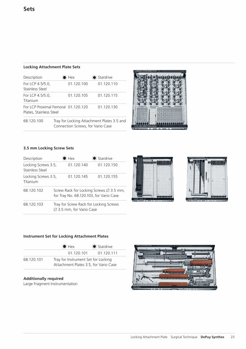
Sets
Locking Attachment Plate Sets
Description Hex Stardrive
For LCP 4.5/5.0, 01.120.100 01.120.110Stainless Steel
For LCP 4.5/5.0, 01.120.105 01.120.115Titanium
For LCP Proximal Femoral 01.120.120 01.120.130Plates, Stainless Steel
68.120.100 Tray for Locking Attachment Plates 3.5 and Connection Screws, for Vario Case
Instrument Set for Locking Attachment Plates
Hex Stardrive
01.120.101 01.120.111
68.120.101 Tray for Instrument Set for Locking Attachment Plates 3.5, for Vario Case
Additionally requiredLarge Fragment Instrumentation
3.5 mm Locking Screw Sets
Description Hex Stardrive
Locking Screws 3.5, 01.120.140 01.120.150Stainless Steel
Locking Screws 3.5, 01.120.145 01.120.155Titanium
68.120.102 Screw Rack for Locking Screws B 3.5 mm, for Tray No. 68.120.103, for Vario Case
68.120.103 Tray for Screw Rack for Locking Screws B 3.5 mm, for Vario Case

24 DePuy Synthes Locking Attachment Plate Surgical Technique
Bibliography
Dumpies, C. W., et al. «[Locking attachment plate - first experience].» Z.Orthop.Unfall. 150.3(2012): 302-08.
Lenz, M., et al. «The locking attachment plate for proximal fixation of periprosthetic femur fractures - a biomechanical comparison of two techniques.» Int.Orthop. 36.9 (2012): 1915-21.

Locking Attachment Plate Surgical Technique DePuy Synthes 25
MRI Information
Torque, Displacement and Image Artifacts according to ASTM F 2213-06, ASTM F 2052-06e1 and ASTM F2119-07Non-clinical testing of worst case scenario in a 3 T MRI system did not reveal any relevant torque or displacement of the construct for an experimentally measured local spatial gradient of the magnetic field of 3.69 T/m. The largest image artifact extended approximately 169 mm from the construct when scanned using the Gradient Echo (GE). Testing was conducted on a 3 T MRI system.
Radio-Frequency-(RF-)induced heating according to ASTM F2182-11aNon-clinical electromagnetic and thermal testing of worst case scenario lead to peak temperature rise of 9.5 °C with an average temperature rise of 6.6 °C (1.5 T) and a peak temperature rise of 5.9 °C (3 T) under MRI Conditions using RF Coils [whole body averaged specific absorption rate (SAR) of 2 W/kg for 6 minutes (1.5 T) and for 15 minutes (3 T)].
Precautions: The above mentioned test relies on non-clini-cal testing. The actual temperature rise in the patient will depend on a variety of factors beyond the SAR and time of RF application. Thus, it is recommended to pay particular attention to the following points: – It is recommended to thoroughly monitor patients under-
going MR scanning for perceived temperature and/or pain sensations.
– Patients with impaired thermo regulation or temperature sensation should be excluded from MR scanning proce-dures.
– Generally it is recommended to use a MR system with low field strength in the presence of conductive implants. The employed specific absorption rate (SAR) should be reduced as far as possible.
– Using the ventilation system may further contribute to reduce temperature increase in the body.


0123
Synthes GmbHEimattstrasse 34436 OberdorfSwitzerlandTel: +41 61 965 61 11Fax: +41 61 965 66 00www.depuysynthes.com
This publication is not intended for distribution in the USA.
All surgical techniques are available as PDF files at www.depuysynthes.com/ifu ©
DeP
uy S
ynth
es T
raum
a, a
div
isio
n of
Syn
thes
Gm
bH. 2
015.
A
ll rig
hts
rese
rved
. 03
6.0
00.
522
DSE
M/T
RM
/031
4/0
001
(1)
09/1
5