LOAD TRANSFER PLATFORMS BEHAVIOR BUILT OVER … · LOAD TRANSFER PLATFORMS BEHAVIOR BUILT OVER JET...
10
LOAD TRANSFER PLATFORMS BEHAVIOR BUILT OVER JET GROUTING COLUMNS AND CUTTER SOIL MIXING PANELS Maria B. M. C. Roma Instituto Superior Técnico, Av. Rovisco Pais, 1049-001 Lisboa, Portugal E-mail: [email protected] ABSTRACT Abstract – It is becoming increasingly urgent the study and development of ground improvement techniques for carrying out works in places of poor geotechnical characteristics. This paper focuses on the comparison between three of these techniques: Stone Columns, Jet Grouting and Cutter Soil Mixing. In this context, a brief explanation of this techniques is presented with reference to its applicability, which are their conditions of use, their procedures, the equipments used and support yard, advantages and disadvantages and also the importance of quality control. As a case of study presents the work carried out in the Cruise Terminal of Santa Apolónia (Lisboa, Portugal), where the results of tests of Jet Grouting columns and Cutter Soil Mixing panels, made in the Landfill of Jardim do Tabaco Dock (Lisboa, Portugal), were essential for the numerical analysis with finite element, made for both techniques. This work was carried out with Jet Grouting columns and the results of instrumentation served to adjust the parameters of the numerical analysis and then make the comparison with Cutter Soil Mixing panels. As a conclusion of the analysis can be said that the two techniques were viable and able to this case, and the two were similar in terms of displacement values. 1. INTRODUCTION It is urgent the construction in places of poor geotechnical characteristics, that’s why the study of ground improvement techniques is so important. These studies are based on acquired knowledge over the years using these techniques with appropriate instrumentation. In this paper it is presented the study of three ground improvement techniques, Stone Columns, Jet Grouting and Cutter Soil Mixing, and the analysis of load transfer platforms built over Jet Grouting Columns and Cutter soil Mixing Panels. The results of the analysis made to Jet Grouting Columns was compared with the results of tests and instrumentation, in order to confirm the model adopted in the analysis and to compare with a similar model with Cutter Soil Mixing panels. 2. GROUND IMPROVEMENT TECHNIQUES The ground improvement techniques are used for improve soil properties such as deformability, permeability and resistance. 2.1. Stone Columns The first documented utilization of this kind of technique was the Taj Mahal’s fundations, after that it was used in 1930 in France, and than since 1950. Vibro replacement stone columns have been used to increase bearing capacity, and decrease settlement and mitigate liquefaction potential. Vibro replacement is a ground improvement technique that constructs dense aggregate columns (stone columns) by means of a crane-suspended downhole vibrator. The vibrator penetrates to the design depth by means of the vibrator’s weight and vibrations, as well as water or air jets located in the vibrator’s tip. The stone is then introduced and fills the void created as the vibrator is lifted several feet. The vibrator is lowered, densifying and displacing the underlying stone. The vibro replacement process is repeated until a dense stone column is constructed to the
-
Upload
phamkhuong -
Category
Documents
-
view
217 -
download
0
Transcript of LOAD TRANSFER PLATFORMS BEHAVIOR BUILT OVER … · LOAD TRANSFER PLATFORMS BEHAVIOR BUILT OVER JET...

LOAD TRANSFER PLATFORMS BEHAVIOR BUILT OVER JET GROUTING
COLUMNS AND CUTTER SOIL MIXING PANELS
Maria B. M. C. Roma
Instituto Superior Técnico, Av. Rovisco Pais, 1049-001 Lisboa, Portugal
E-mail: [email protected]
ABSTRACT
Abstract – It is becoming increasingly urgent the study and development of ground improvement techniques for carrying out works in places of poor geotechnical characteristics. This paper focuses on the comparison between three of these techniques: Stone Columns, Jet Grouting and Cutter Soil Mixing. In this context, a brief explanation of this techniques is presented with reference to its applicability, which are their conditions of use, their procedures, the equipments used and support yard, advantages and disadvantages and also the importance of quality control. As a case of study presents the work carried out in the Cruise Terminal of Santa Apolónia (Lisboa, Portugal), where the results of tests of Jet Grouting columns and Cutter Soil Mixing panels, made in the Landfill of Jardim do Tabaco Dock (Lisboa, Portugal), were essential for the numerical analysis with finite element, made for both techniques. This work was carried out with Jet Grouting columns and the results of instrumentation served to adjust the parameters of the numerical analysis and then make the comparison with Cutter Soil Mixing panels. As a conclusion of the analysis can be said that the two techniques were viable and able to this case, and the two were similar in terms of displacement values.
1. INTRODUCTION It is urgent the construction in places of poor geotechnical characteristics, that’s why the study of ground improvement techniques is so important. These studies are based on acquired knowledge over the years using these techniques with appropriate
instrumentation. In this paper it is presented the study of three ground improvement techniques, Stone Columns, Jet Grouting and Cutter Soil Mixing, and the analysis of load transfer platforms built over Jet Grouting Columns and Cutter soil Mixing Panels. The results of the analysis made to Jet Grouting Columns was compared with the results of tests and instrumentation, in order to confirm the model adopted in the analysis and to compare with a similar model with Cutter Soil Mixing panels.
2. GROUND IMPROVEMENT TECHNIQUES
The ground improvement techniques are used for improve soil properties such as deformability, permeability and resistance.
2.1. Stone Columns The first documented utilization of this kind of technique was the Taj Mahal’s fundations, after that it was used in 1930 in France, and than since 1950. Vibro replacement stone columns have been used to increase bearing capacity, and decrease settlement and mitigate liquefaction potential. Vibro replacement is a ground improvement technique that constructs dense aggregate columns (stone columns) by means of a crane-suspended downhole vibrator. The vibrator penetrates to the design depth by means of the vibrator’s weight and vibrations, as well as water or air jets located in the vibrator’s tip. The stone is then introduced and fills the void created as the vibrator is lifted several feet. The vibrator is lowered, densifying and displacing the underlying stone. The vibro replacement process is repeated until a dense stone column is constructed to the

ground surface. [1] The vibrator is essential for the compression and lateral expansion of stone and, due to its weight ensures the verticality of the column.
Fig. 1 – Construction process of Stone Columns
The interaction between the column and the soil around them leads to a redistribution of efforts, and consequently increase of the resistance parameters. [2] This columns working as a drain enable the radial flow. The effect caused by the "double flow"(vertical and radial flow) and the fact that normally there is a stone columns mesh in the area, originates a settlement of 90% in the construction period. It is a suitable technique for soils with low resistance or heterogeneous landfills. It is used in landfill foundations or foundations with low and distributed loads. Stone columns can be fully instrumented with an on-board computer to monitor specific parameters. Monitoring these parameters allows the operator to correct any deviations in real-time during the construction process to keep the stone column within project specifications.
2.2. Jet Grouting The Jet Grouting technology was developded in the 70’s, in Japan. Is being used in Europel since the last twenty years as ground improvement solution. It is used in ground treatment for foundations of every kind of structures, including load transfer platforms, slope stabilization, earth retaining structures, underpin existing foundations among other examples. The technology is appropriated to many ground conditions, a big advantage in places with very heterogeneous geological conditions. [3]. Jet grouting is a grouting technique that creates in situ geometries of soilcrete, using a grouting monitor attached to the end of a drill stem. The jet grout monitor is advanced to the maximum treatment depth, at which time high velocity grout jets (and sometimes
water and air) are initiated from ports in the side of the monitor. The jets erode and mix the in situ soil as the drill stem and jet grout monitor are rotated and raised.
Fig. 2 – Construction process of Jet Grouting
Depending on the application and soils to be treated, one of three variations is used: the single fluid system (grout jet), the double fluid system (grout jet with air jet) and the triple fluid system (grout, air and water jet). Jet grouting is effective across the widest range of soil types, including silts and some clays. [1] There are several parameters that influence the results of Jet Grouting Columns, among them stand out the geotechnical characteristics of the soil, the percentage of soil replacement, the uniformity of treatment in depth and geometry. In relation to the geotechnical characteristics it can be seen that the greater ground grain greater will be the diameters of the columns. Non cohesive soils are typically more erodible by jet grouting than cohesive soils. The clays and silts, with larger amounts of fines, have greater plasticity, therefore greater consistency and cohesiveness which increase the pressure in the grout injection. Due to this pressure, since it is to add material to the natural soil is produced a reflux surplus material, it is important that is brought to the appropriate place. This reflux is one of the factors of the quality control, which should be thick and have soil in its constitution, indicative of a good mix. When there is no reflux can mean that are forming balls instead of columns. There is a on-board computer to monitor the process and this instrumentation is part of the quality control plan. [1]
2.3. Cutter Soil Mixing
Bauer developed the Cutter-Soil-Mixing technique in 2003 by drawing on the experience gained in the production and deployment of diaphragm wall cutters which

are used in the construction of cut-off and diaphragm retaining walls. It can be considered a type of “Mechanic Jet Grouting”, as soil mixture is mechanically made. This technique is one of the Wet Deep Mixing techniques (wet linker transportation). Cutter Soil Mixing is an effective method constructing: cutt-off walls; earth retaining walls; soil improvement or for constructing foundation elements, stabilizing soft or loose soils (non cohesive and cohesive). The soil matrix is broken by cutting wheels and bentonit slurry is pumped and mixed up with the soil. After reaching the design depth, the mixing tool is slowly extracted while blinder slurry is continuously added. Homogenization of the fluidified soil mixture is ensured by the rotation of the wheels.
Fig. 3 - Construction process of Cutter Soil Mixing
There are three types of cutting wheels, chosen according to the soil. The type 1 are suitable for sandy soils, non cohesive and easy breakdown; the wheels of the type 2 used in silty or sandy soils, whose particles have very thin granulometry; wheels type 3 applies in hard and dense soils with presence of rocky blocks. The Cutter Soil Mixing panels can be performed in two types of systems, the system of one phase and the two phases. In the one-phase system during the descending movement blinder slurry is injected, approximately 2/3 of the slurry, the remaining slurry is introduced into the ascending phase. This system is indicated for mild and uniform soils with low compactness. In the two-phase system the soil is fluidified and homogenised in the downstroke phase by pumping of bentonite slurry into the soil. After reaching the design depth, the flow bentonite is stopped and replaced by cement slurry. On the upstroke movement, cement slurry is mixed thoroughly with the fluidified soil. It is widely used in building waterproofing curtains and heterogeneous soils and of high compactness.
The backflow of soil and blinder slurry is collected to appropriated local. As instrumentation, there are in the machine an electronic monitoring and control system is installed in the equipment and monitors and controls construction parameters and functions. [4]
3. CASE STUDY It is presented a case history of the load transfer platform foundation adopted for the fill of the “Jardim do Tabaco” dockyard, including the closing and refurbishment of the “Jardim do Tabaco” centenary masonry quay walls. The site is located at the Tagus River right bank in Lisbon, where the jet grouting technology was applied with success on very complex neighborhood and geological conditions, including Miocene weak rocks, sandstones, hard soils, and dense sands.
3.1. Main Conditions
The landfill of the dockyard was built over soft alluvium soils with 20 m of average depth, including at the bottom a layer of muddy sands, resting over the Miocene sandstones and dense sands. It was built with the purpose to allow the construction of the new “Santa Apolónia” Cruise Terminal. Other main issues were the need for the preservation of the adjacent old buildings and infrastructures stability, including one ϕ1000mm water pipe and the Lisbon Metro line, as well as the quay walls integrity. In order to better resist to the new landfill earth pressures and to confine the soft soils under the fill, the quay walls were previously refurbished and the dockyard gate previously closed. [3]
3.2. Solutions
Taking into account the existent conditions, mainly the complex working area, as well as the works schedule, the landfill was built over a load transfer platform, located over jet grouting ϕ1,5 m columns on a 5,7 x 5,7 m
2 mesh and resting at the Miocene
sandstones and dense sands, installed during low tide.
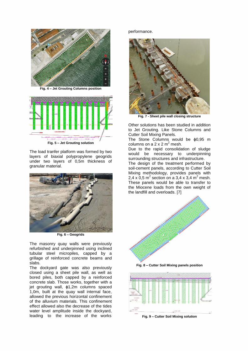
Fig. 4 – Jet Grouting Columns position
Fig. 5 – Jet Grouting solution
The load tranfer platform was formed by two layers of biaxial polypropylene geogrids under two layers of 0,5m thickness of granular material.
Fig. 6 – Geogrids
The masonry quay walls were previously refurbished and underpinned using inclined tubular steel micropiles, capped by a grillage of reinforced concrete beams and slabs. The dockyard gate was also previously closed using a sheet pile wall, as well as bored piles, both capped by a reinforced concrete slab. Those works, together with a jet grouting wall, ϕ1,2m columns spaced 1,0m, built at the quay wall internal face, allowed the previous horizontal confinement of the alluvium materials. This confinement effect allowed also the decrease of the tides water level amplitude inside the dockyard, leading to the increase of the works
performance.
Fig. 7 - Sheet pile wall closing structure
Other solutions has been studied in addition to Jet Grouting. Like Stone Columns and Cutter Soil Mixing Panels. The Stone Columns would be ϕ0,95 m columns on a 2 x 2 m
2 mesh.
Due to the rapid consolidation of sludge would be necessary to underpinning surrounding structures and infrastructure. The design of the treatment performed by soil-cement panels, according to Cutter Soil Mixing methodology, provides panels with 2,4 x 0,5 m
2 section on a 3,4 x 3,4 m
2 mesh.
These panels would be able to transfer to the Miocene loads from the own weight of the landfill and overloads. [7]
Fig. 8 – Cutter Soil Mixing panels position
Fig. 9 – Cutter Soil Mixing solution

To support the loads of the new structure of Terminal Jet Grouting was reinforced with tubular steel micropiles N80 – API5A Φ244,5×16,0 + 1Φ50 mm (A500/A550). In the case of Cutter Soil Mixing, the panels should have a steel section reinforcement equivalent of the micropile used in the case of Jet Grouting.
3.3. Quality control and monitoring
The performance of the solution was monitored through an instrumentation plan, during the jet grouting and earth works. The instrumentation plan comprised the installation of topographic marks at the landfill base, as well as rod extensometers at the load tranfer platform geogrids and pressure cells at the jet grouting columns head. The execution of the Jet Grouting columns was complemented by a tight quality control and quality assurance, allowing the confirmation of the resistance, deformability and geometry of the columns. For this purpose, test columns were built and tests done in order to confirm the geometry and to perform laboratory tests. During the execution of the jet grouting columns a permanent registration of all the adopted parameters was also performed, allowing to confirm the columns overall length. [3]
4. ANALYSIS AND MODELING
4.1. Plaxis software Plaxis is a finite element package that has been developed for the analysis of deformation and stability in geotechnical engineering projects. [5] Some models of soil behavior are pré-instaled in this software, like the ones used at this analysis, Mohr-Coulomb model and Hardening Soil model, to modeling the walls and the soil. The Hardening Soil model derived from the Mohr-Coulomb model (perfectly elastoplastic model with a fixed surface), but based on the theory of plasticity with no fixed surface and utilizes three stiffnesses to the definition of each soil, the triaxial loading stiffness, E50, the triaxia unloading stiffness, Eur, and the oedometer loading stiffness, Eoed. The model involves compression hardening to simulate irreversible compaction of soil under primary
compression. [6] The Jet Grouting columns and Cutter Soil Mixing panels were model by the element Plate, with elastic behavior. The Load Tranfer Platform was model by an geogrid element with elastic behavior.
4.2. Design
When the geometry model is fully defined and material properties are assingned to all clusters and structural objects, the geometry has to be divided into finite elements in order to perform the calculations. In this analysis it was considered an area of 110 x 25 m. The geogrid as EA = 1000 kN/m. Any other value introduced in the software is shown in the nexts tables.
Material Riprap Walls LTP
Type Un-
drained
Un-
drained Drained
γh
(kN/m3)
19 22 17
γsat
(kN/m3)
20 23 18
Eref
(MPa) 80 100 60
ν 0,2 0,18 0,25
cref
(kPa) - - 0,1
Φ’ (°) 36 45 35
Ψ (°) 6 15 5
Fig. 10 – Parameters of the Mohr-Coulomb model

Mat
erial
Lan
dfill
Sandy
silt
Clayey
silt
Mioce
ne
Typ
e
Dra
ine
d
Un-
drained
Un-
drained
Un-
draine
d
γh
(kN/
m3)
18 17 16 18
γsat
(kN/
m3)
19 18 17 19
E50re
f
(MP
a)
12 3 0,5 60
Eoed
ref
(MP
a)
10,
8 2,7 0,45 54
Eurre
f
(MP
a)
36 9 1,5 18
K0 0,4
26 0,577 0,674 0,5
cref
(kP
a)
0,1 - - -
Φ’
(°) 35 25 19 30
Ψ
(°) 5 0 0 0
Fig. 11 – Parameters of the Hardening Soil model
Material Jet Grouting
r (m) 0,75
A (m2) 1,77
I (m4) 0,249
E (MPa) 390
EA (kN/m) 114900
EI (kNm2/m) 16150
w (kN/m/m) 5,89
ν 0,15
Spacing os columns (m) 6
Fig. 12 – Parameters of the Jet Grouting Columns
Material Cutter Soil
Mixing
a (m) 2,4
b (m) 0,5
A (m2) 1,2
Ix (m4) 0,025
Iy (m4) 0,576
E (MPa) 390
EA (kN/m) 137600
EI (kNm2/m) 34470
w (kN/m/m) 7,059
ν 0,15
Spacing of panels (m) 3,4
Fig. 13 – Parameters of the Cutter Soil Mixing Panels
4.4. Results comparation
The total stresses are shown in Figures 14 and 15, with maximum stresses located in the transiction to Miocene with value: σJG = - 525,37 kN / m
2 σCSM = - 554,96 kN / m
2.
Fig. 14 – Total stresses on the Jet Grouting model

Fig. 15 – Total stresses on the Cutter Soil Mixing model
The vertical displacement achieved by the program reflect a maximum of 0,23 m, for Jet Grouting model in the inner zone of the dockyard nearer the south walls, figure 16. The maximum values recorded by topographic targets were also in this area, but higher values was recorder, near 0,30 m. This discrepancy values can be justified by approaches made in the input values of and other considerations that have been disregarded, as the case of the micropiles used to stabilize the walls. In any case fall within the recommended values in design and much lower than the warning or alarm criteria taxes.
Fig. 16 – Vertical displacements using Jet Grouting
Vertical maximum displacements obtained for Cutter Soil Mixing model were 0,25 m, in the area near to the north wall of the dockyard, figure 17. In area where the in the Jet Grouting was founded the largest vertical displacements with the Cutter Soil Mixing technique the displacements are similar.
Fig. 17 – Vertical displacements using Cutter Soil
Mixing
The Jet Grouting column located at the place where the greatest displacements occurred presents the values: δ
vmax = 0,17 m
and Nmax = - 246,12 kN / m. The Cutter Soil Mixing panel located at the place where the greatest displacements occurred presents the values: δ
vmax = 0,19 m
and Nmax = - 151,91 kN / m. The geogrid presents the following values of axial load: NJG
max = 8,44 kN/m e NCSM
max =
27,30 kN/m.
4.4. Results comparation The displacements recorded in the Cutter Soil Mixing model, near the north wall of the dockyard can be explained by the short length of the panels justified by the existing wall rockfill. In the case of Jet Grouting columns, they have similar length to the other columns. According to the analysis of the instrumentation readings it was possible to conclude that, in spite of the jet grouting columns had been design to resist to all the loads due to the landfill weight and live loads (3,7MPa of unconfined resistance compression), only about 40% of those loads was directly transferred to jet grouting columns head. The remaining 60% of the overall loads were resisted by the confined muddy alluvium and transferred to the jet grouting columns shaft at a small depth. The main reason for this situation was the increase of the mud overall bearing capacity, due to the 3D confinement effect, which could be explained by the following main issues: at the top of the mud: due to the
upper landfill; at the base of the mud: due to the Miocene layer; horizontally: due to the jet grouting columns and to the peripheral quay and retaining walls. [3] For the study of the loads likely to be imposed on Jet Grouting columns were followed load tests carried out on some Jet Grouting columns. Vertical load tests are used to verify the vertical deformation of the Jet Grouting columns armed with micropiles, to assess mobilized stresses along the column and its carrying capacity. [8] With the horizontal load tests is possible evaluate horizontal deformation of the columns and micropiles and its horizontal loading capacity, when requested by a horizontal load in its head. [9] The vertical load test was made with an axial compression load of 6000 kN applied to the head of the column. This load value is about twice its value in service. The degradation of the load applied to the group "Column + Micropile" was estimated from the observed shortening and some features of the micropiles and Jet Grouting columns. In this analysis the degradation of the axial load of the whole "Column + Micropile" was considered linear.

Fig. 18 – Vertical displacements
Verifies that plastic displacements are reduced, of about 10 mm, well below the elastic settlements, which discloses a predominantly elastic behavior, coincident with the numerical analysis defined in this work. It is visible in the figure 19, the pressure drop phenomenon by lateral friction of the group "Column + Micropile". It also can be seen that about 20 to 30% of the load applied to the column head is transmitted to the soil in the bottom.
Fig. 19 – Load degradation
The horizontal test load was made with a load estimated maximum 6000 kN, which represents about 15% of the estimated vertical load of service. Through the relative horizontal displacements of the head of the column under the applied load, it is possible to determine (for each level) equivalent horizontal stiffness of the head of the column.
Fig. 20 – Load /Horizontal displacement
In the following graph can be seen the development of the horizontal stiffness with the variation of installed load. The stiffness does not reach the value zero, this means that the column not fully plasticize, therefore, the horizontal load capacity would not be exhausted.
Fig. 21 – Load /Horizontal stiffness
The yellow line is a continuous approach of discrete records stiffness obtained in the test. The results and conclusions of the tests helped confirm the overall carrying capacity of the group “Column + Micropile" as the future TCSA foundations, whose project is already done and in it the pillars have clearance of 8,0 m and are of circular section of ϕ80 cm. It’s a solution perfectly compatible with the columns of Jet Grouting reinforced with micropiles.
5. CONCLUSIONS
It was made a comparison between two techniques increasingly recurrent: Jet Grouting and Cutter Soil Mixing. Another technique was also studied, the Stone Columns method, which was ruled out because it would cause deep settlements over time due to the consolidation of the mud, and could affect the structures and surrounding infrastructure.

The results of tests made in Jet Grouting columns and soil-cement panels made with the Cutter Soil Mixing technique were used to do numerical analysis of the two techniques and compar with results of load tests made in the Jet Grouting columns and with results of instrumentation placed in the field. The two tecniques are similer in costs, time of execution and displacments. The treatment was made by Jet Grouting Columns because it allowed their inclusion, since armed with micropiles, as building foundations of Cruise Terminal. The project of the building has the pillars in alignment of columns.
Fig. 22 – Building plan/JG position
It would have been interesting to have been planned in advance the various projects in order to make them compatible to avoid building a soil treatment solution, destroying part of that solution to rebuild the Santa Apolónia Cruise Terminal foundations.
REFERENCES
[1] - www.haywardbaker.com
[2] - PRIEBE, H. J., Vibro replacement to prevent earthquake induced liquefaction, Ground Engineering Revue, 1998. [3] - A. Pinto1 & R. Tomásio, J. Ravasco, G. Marques, Fill of the “Terreiro do Trigo” Dockyard in Lisbon over Alluvial and Hard Soils. [4] - www.bauer.de [5] - Manual de Referência Plaxis V8, manual explicativo da utilização do Plaxis. [6] - Material Manual Plaxis V8, Manual dos modelos constitutivos do Plaxis. [7] - RIBEIRO, Ana, Técnica de tratamento de solos – Jet Grouting, Acompanhamento de um caso real de estudo – Cais de Santa Apolónia e Jardim do Tabaco, Tese de
Mestrado, Lisboa: UL/IST, 2010. [8] - PINTO, Alexandre, TOMÁSIO, Rui, Análise Final dos Ensaios de Carga Vertical de Compressão de uma Coluna de Jet Grouting de Fundação, Lisboa, Março de 2011. [9] - PINTO, Alexandre, TOMÁSIO, Rui, Análise Final dos Ensaios de Carga Horizontal de duas Colunas de Jet Grouting de Fundação, Lisboa, Setembro de 2011.