Load Modeling
14
Power Planners International Load Modeling for Dynamic Studies EOA Head Office, Dammam Dec. 01 – Dec 05, 2013 PSS/E Training Course for NG SA Week 2 Day-1-C
-
Upload
touseef-hussain -
Category
Documents
-
view
191 -
download
9
Transcript of Load Modeling
Power Planners International
Load Modeling for Dynamic Studies
EOA Head Office, Dammam Dec. 01 – Dec 05, 2013
PSS/E Training Course for NG SA
Week 2 Day-1-C
Khaleel
Typewritten Text
1. Voltage Dependant 2. Frequency Dependant
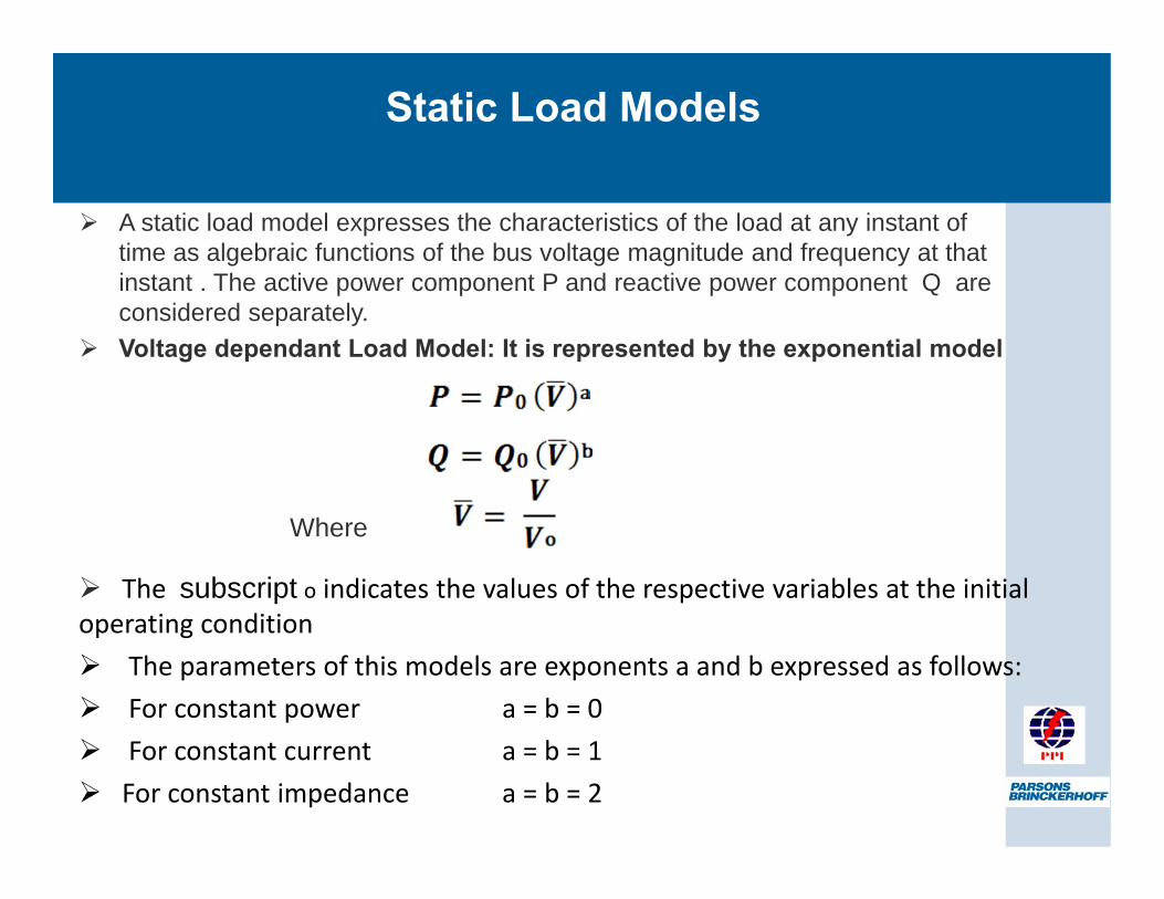
The subscript o indicates the values of the respective variables at the initial operating condition The parameters of this models are exponents a and b expressed as follows: For constant power a = b = 0 For constant current a = b = 1 For constant impedance a = b = 2
Static Load Models
A static load model expresses the characteristics of the load at any instant of time as algebraic functions of the bus voltage magnitude and frequency at that instant . The active power component P and reactive power component Q are considered separately. Voltage dependant Load Model: It is represented by the exponential model
Where
Khaleel
Rectangle
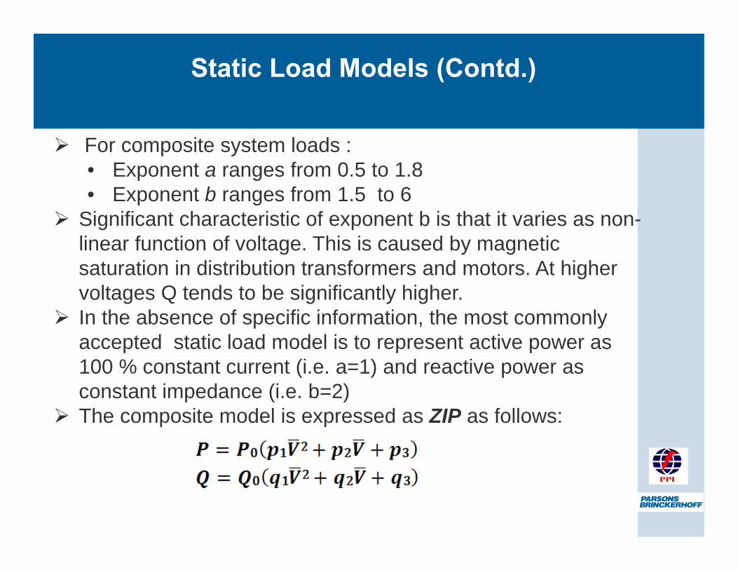
Static Load Models (Contd.)
For composite system loads : • Exponent a ranges from 0.5 to 1.8 • Exponent b ranges from 1.5 to 6
Significant characteristic of exponent b is that it varies as non-linear function of voltage. This is caused by magnetic saturation in distribution transformers and motors. At higher voltages Q tends to be significantly higher. In the absence of specific information, the most commonly accepted static load model is to represent active power as 100 % constant current (i.e. a=1) and reactive power as constant impedance (i.e. b=2) The composite model is expressed as ZIP as follows:
Khaleel
Rectangle
Khaleel
Typewritten Text
Commonly Converted Form, most stringent case (more conservative)
Khaleel
Typewritten Text
Static Load Models Contd.
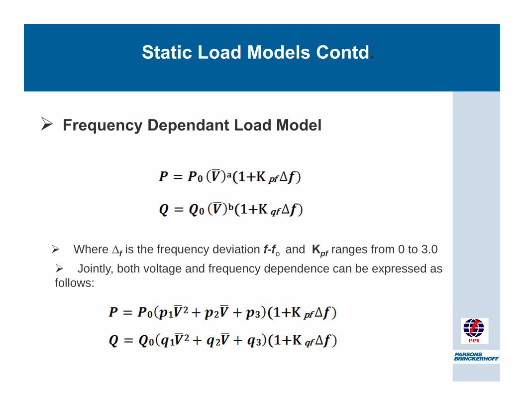
Frequency Dependant Load Model
Where ∆f is the frequency deviation f-fo and Kpf ranges from 0 to 3.0 Jointly, both voltage and frequency dependence can be expressed as
follows:
Khaleel
Callout
Combined Voltage and Frequency Model
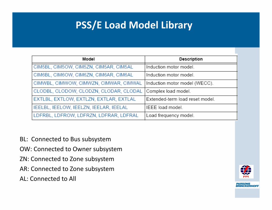
BL: Connected to Bus subsystem OW: Connected to Owner subsystem ZN: Connected to Zone subsystem AR: Connected to Zone subsystem AL: Connected to All
PSS/E Load Model Library
Khaleel
Typewritten Text
DYNAMIC MODELS
Khaleel
Line
Khaleel
Line
Khaleel
Line
Khaleel
Line
Khaleel
Line
Khaleel
Typewritten Text
Purely Inductive Models
Khaleel
Typewritten Text
No need for seprt R1, R2
Khaleel
Typewritten Text
Rather specify the % of indiv. loads
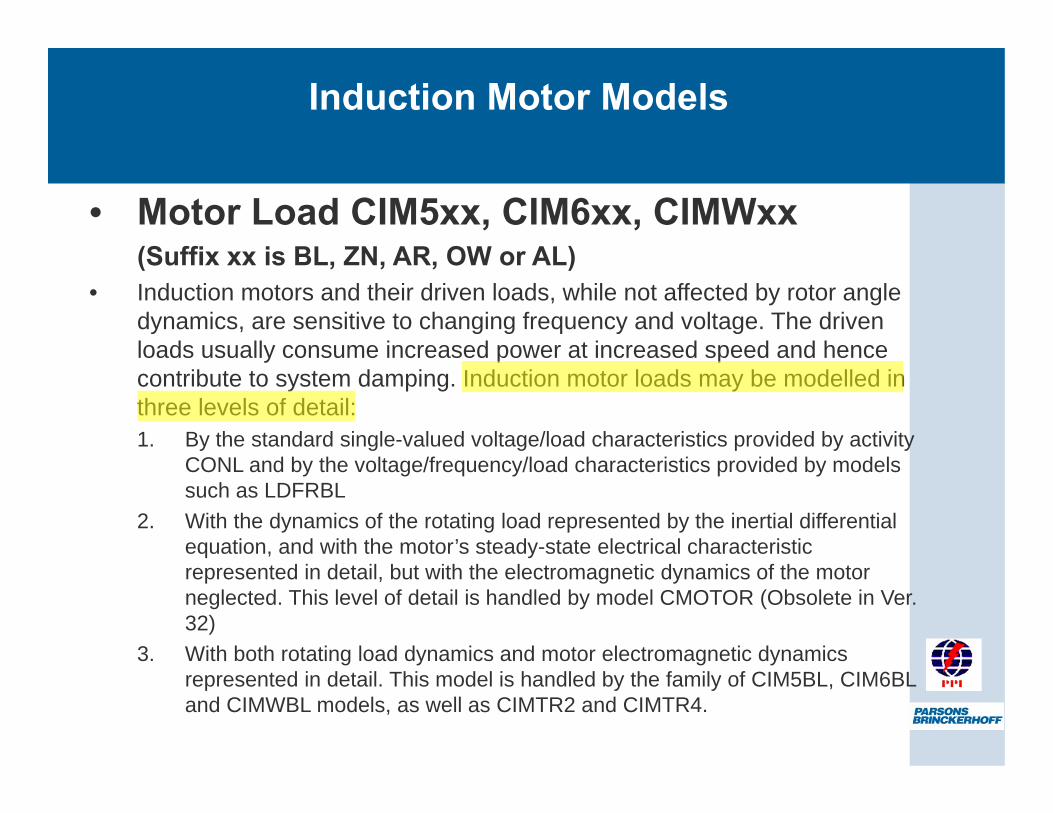
• Motor Load CIM5xx, CIM6xx, CIMWxx (Suffix xx is BL, ZN, AR, OW or AL)
• Induction motors and their driven loads, while not affected by rotor angle dynamics, are sensitive to changing frequency and voltage. The driven loads usually consume increased power at increased speed and hence contribute to system damping. Induction motor loads may be modelled in three levels of detail: 1. By the standard single-valued voltage/load characteristics provided by activity
CONL and by the voltage/frequency/load characteristics provided by models such as LDFRBL
2. With the dynamics of the rotating load represented by the inertial differential equation, and with the motor’s steady-state electrical characteristic represented in detail, but with the electromagnetic dynamics of the motor neglected. This level of detail is handled by model CMOTOR (Obsolete in Ver. 32)
3. With both rotating load dynamics and motor electromagnetic dynamics represented in detail. This model is handled by the family of CIM5BL, CIM6BL and CIMWBL models, as well as CIMTR2 and CIMTR4.
Induction Motor Models
Khaleel
Highlight
Induction Motor Models
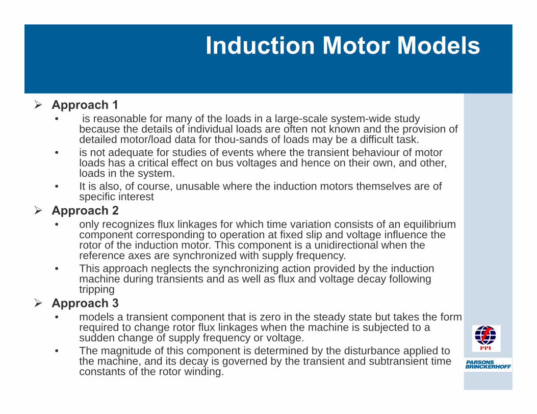
Approach 1 • is reasonable for many of the loads in a large-scale system-wide study
because the details of individual loads are often not known and the provision of detailed motor/load data for thou-sands of loads may be a difficult task.
• is not adequate for studies of events where the transient behaviour of motor loads has a critical effect on bus voltages and hence on their own, and other, loads in the system.
• It is also, of course, unusable where the induction motors themselves are of specific interest
Approach 2 • only recognizes flux linkages for which time variation consists of an equilibrium
component corresponding to operation at fixed slip and voltage influence the rotor of the induction motor. This component is a unidirectional when the reference axes are synchronized with supply frequency.
• This approach neglects the synchronizing action provided by the induction machine during transients and as well as flux and voltage decay following tripping
Approach 3 • models a transient component that is zero in the steady state but takes the form
required to change rotor flux linkages when the machine is subjected to a sudden change of supply frequency or voltage.
• The magnitude of this component is determined by the disturbance applied to the machine, and its decay is governed by the transient and subtransient time constants of the rotor winding.
Khaleel
Callout
Most Appropriate
Induction Motor Models
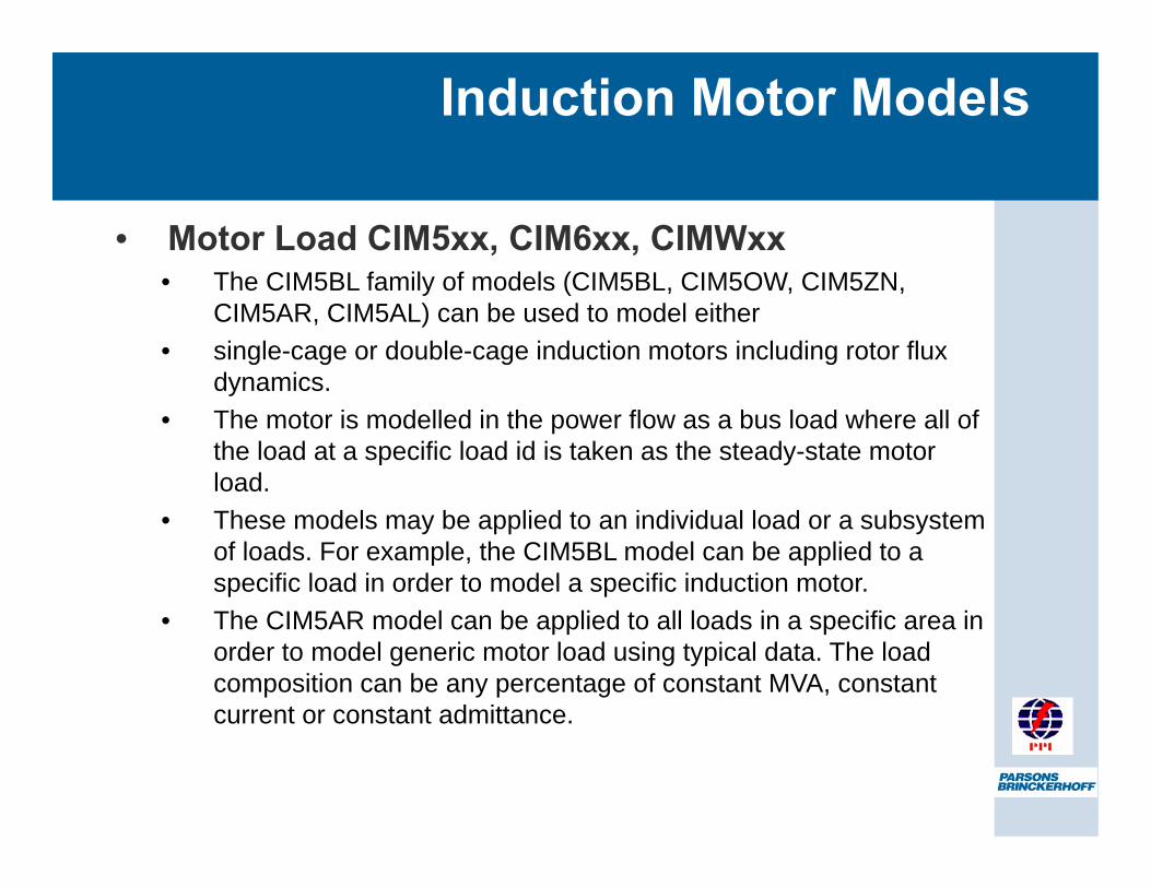
• Motor Load CIM5xx, CIM6xx, CIMWxx • The CIM5BL family of models (CIM5BL, CIM5OW, CIM5ZN,
CIM5AR, CIM5AL) can be used to model either • single-cage or double-cage induction motors including rotor flux
dynamics. • The motor is modelled in the power flow as a bus load where all of
the load at a specific load id is taken as the steady-state motor load.
• These models may be applied to an individual load or a subsystem of loads. For example, the CIM5BL model can be applied to a specific load in order to model a specific induction motor.
• The CIM5AR model can be applied to all loads in a specific area in order to model generic motor load using typical data. The load composition can be any percentage of constant MVA, constant current or constant admittance.
Induction Motor Models
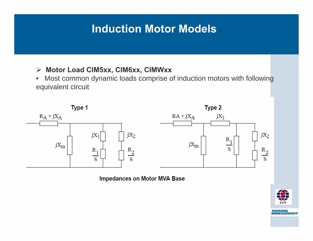
Motor Load CIM5xx, CIM6xx, CIMWxx • Most common dynamic loads comprise of induction motors with following equivalent circuit
Khaleel
Typewritten Text
Stator Impedance
Khaleel
Typewritten Text
Rotor Impedance
Khaleel
Typewritten Text
Leakage
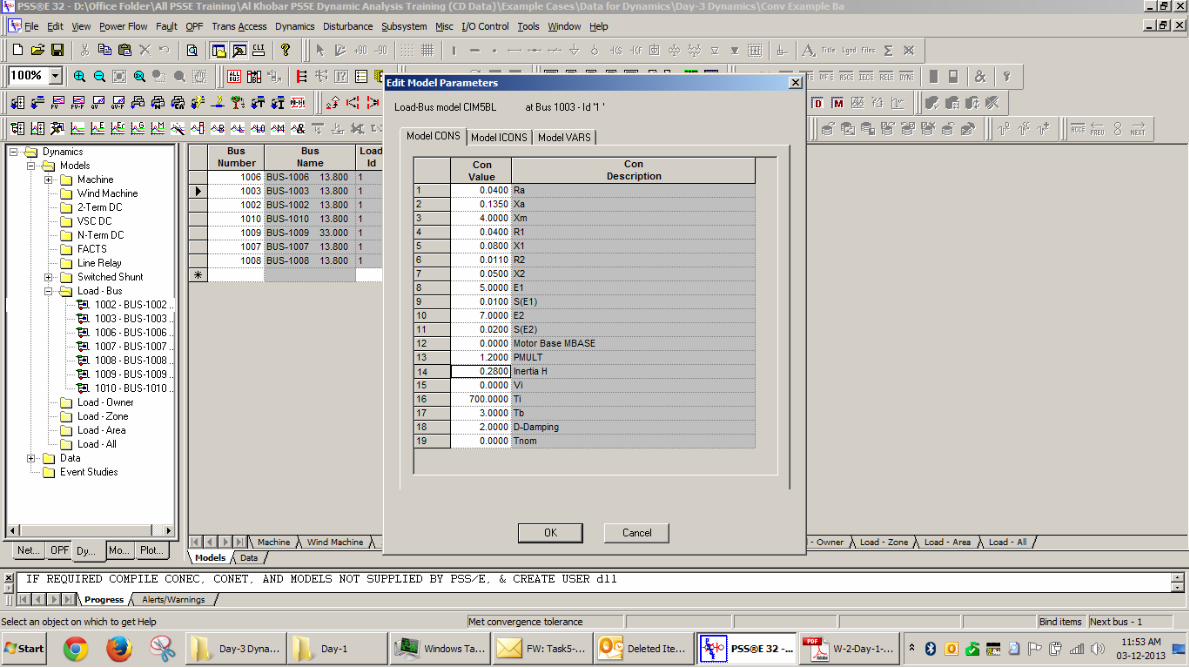
CIM5* Motor Models
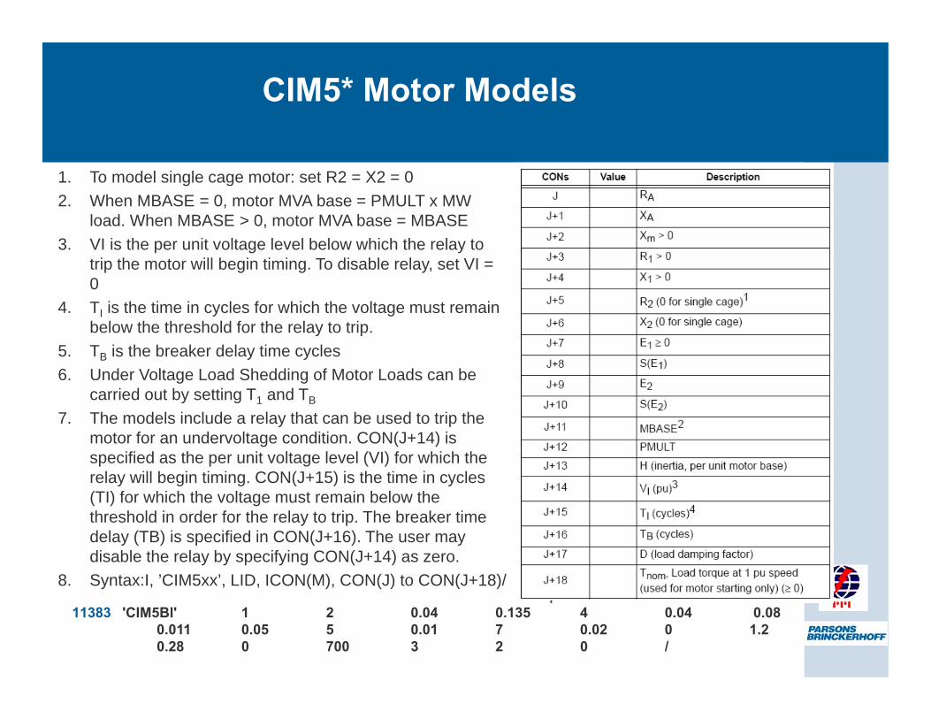
1. To model single cage motor: set R2 = X2 = 0 2. When MBASE = 0, motor MVA base = PMULT x MW
load. When MBASE > 0, motor MVA base = MBASE 3. VI is the per unit voltage level below which the relay to
trip the motor will begin timing. To disable relay, set VI = 0
4. TI is the time in cycles for which the voltage must remain below the threshold for the relay to trip.
5. TB is the breaker delay time cycles 6. Under Voltage Load Shedding of Motor Loads can be
carried out by setting T1 and TB
7. The models include a relay that can be used to trip the motor for an undervoltage condition. CON(J+14) is specified as the per unit voltage level (VI) for which the relay will begin timing. CON(J+15) is the time in cycles (TI) for which the voltage must remain below the threshold in order for the relay to trip. The breaker time delay (TB) is specified in CON(J+16). The user may disable the relay by specifying CON(J+14) as zero.
8. Syntax:I, ’CIM5xx’, LID, ICON(M), CON(J) to CON(J+18)/
11383 'CIM5Bl' 1 2 0.04 0.135 4 0.04 0.08 0.011 0.05 5 0.01 7 0.02 0 1.2 0.28 0 700 3 2 0 /
Khaleel
Callout
We dont want load shedding hence we gave large no of cycles
CIM5xx Motor Models
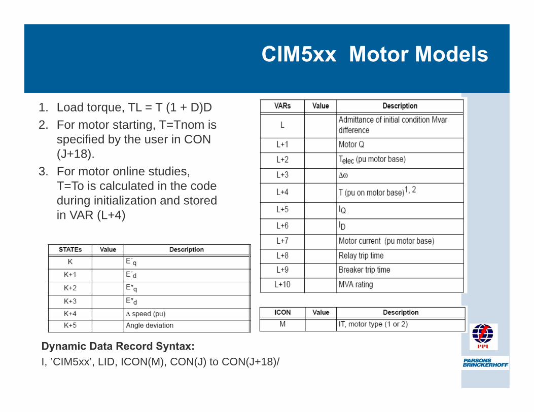
1. Load torque, TL = T (1 + D)D 2. For motor starting, T=Tnom is
specified by the user in CON (J+18).
3. For motor online studies, T=To is calculated in the code during initialization and stored in VAR (L+4)
Dynamic Data Record Syntax: I, ’CIM5xx’, LID, ICON(M), CON(J) to CON(J+18)/
Khaleel
Rectangle
Khaleel
Typewritten Text
Speed Deviation
Khaleel
Rectangle
Khaleel
Typewritten Text
Speed Deviation
Khaleel
Typewritten Text
56
Khaleel
Typewritten Text
57
Khaleel
Typewritten Text
59
Khaleel
Typewritten Text
66
Khaleel
Typewritten Text
150
Khaleel
Typewritten Text
154
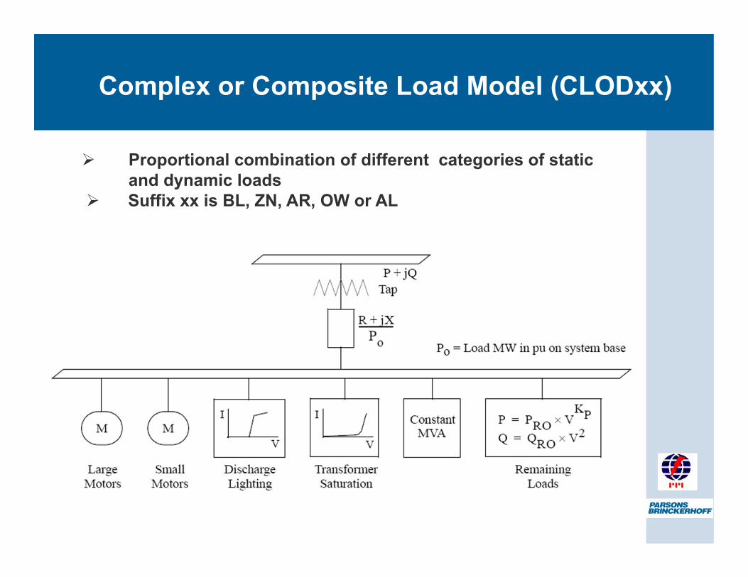
Complex or Composite Load Model (CLODxx)
Proportional combination of different categories of static and dynamic loads
Suffix xx is BL, ZN, AR, OW or AL
Khaleel
Typewritten Text
This model can be used to combine all the loads in PSSE. Values of the Xstator, R rotor etc are taken by degault by PSSSE
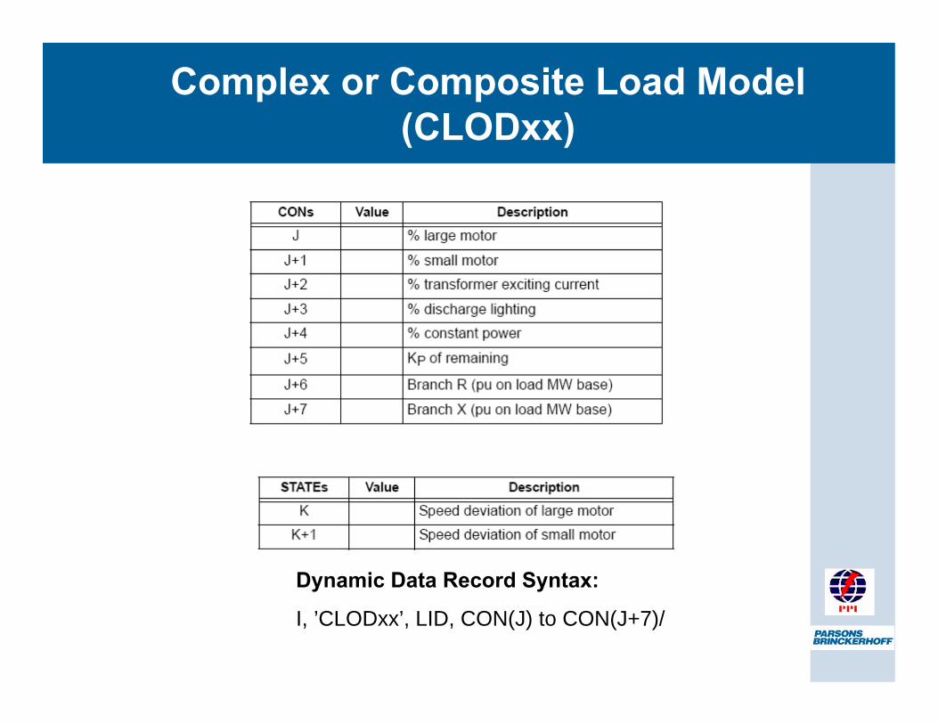
Complex or Composite Load Model (CLODxx)
Dynamic Data Record Syntax:
I, ’CLODxx’, LID, CON(J) to CON(J+7)/
Khaleel
Typewritten Text
Either give MVA or give PMULT which is 1/pf
Khaleel
Typewritten Text
In order not to trip the load we are giving 700 cycles We have rather disabled the relay
Khaleel
Callout
Saturation Constant
Khaleel
Line