Liu C.-K., He H., Sun R.-J., Feng Y., Wang Q.-S. This ...
7
Preparation of continuous nanofiber core-spun yarn by a novel covering method Liu C.-K., He H., Sun R.-J., Feng Y., Wang Q.-S. This accepted author manuscript is copyrighted and published by Elsevier. It is posted here by agreement between Elsevier and MTA. The definitive version of the text was subsequently published in [Materials & Design, 112, 2016, DOI: 10.1016/j.matdes.2016.09.081 ]. Available under license CC-BY-NC-ND. Powered by TCPDF (www.tcpdf.org)
Transcript of Liu C.-K., He H., Sun R.-J., Feng Y., Wang Q.-S. This ...

Preparation of continuous nanofiber core-spun yarn by a novel covering methodLiu C.-K., He H., Sun R.-J., Feng Y., Wang Q.-S.
This accepted author manuscript is copyrighted and published by Elsevier. It is postedhere by agreement between Elsevier and MTA. The definitive version of the text wassubsequently published in [Materials & Design, 112, 2016, DOI: 10.1016/j.matdes.2016.09.081]. Available under license CC-BY-NC-ND.
Powered by TCPDF (www.tcpdf.org)

Preparation of continuous nanofiber core-spun yarn by a novel
covering method
Cheng-Kun Liu a,b,⁎, Hai-Jun He a, Run-Jun Sun a, Yan Feng c, Qiu-shi Wang c
a School of Textile and Materials, Xi'an Polytechnic University, Xi'an 710048, Chinab College of Textiles, Donghua University, Shanghai 201620, Chinac School of Materials Science and Engineering, Xi'an Jiaotong University, Xi'an 710049, China
a b s t r a c ta r t i c l e i n f o
Article history:
Received 11 June 2016
Received in revised form 11 September 2016
Accepted 23 September 2016
Available online 24 September 2016
A novel coveringmethod to fabricate nanofiber core-spun yarn has been developed. Effects of span distance and
rotation speed of disks on morphology, covering effect, abrasion resistance, wicking property, and mechanical
property were mainly discussed in this investigation. Results showed that span distance had a significant effect
on covering effect, and nanofiber core-spun yarnwith a perfect covering effect could be prepared at the span dis-
tance of 2 cmwith covering rate and abrasion growth rate of 30% and 142.3%, respectively. Alignment direction of
nanofibers on the surface of nanofiber core-spun yarn was affected by rotation speed of disks, and would lead to
the changes of wicking property andmechanical property. When the rotation speed of disks was 200 rpm, wick-
ing property of nanofiber core-spun yarn was relatively better with the wicking effect of 7.6 cm. Breaking
strength was decreased first and then increased with the increase of rotation speed.
© 2016 Elsevier Ltd. All rights reserved.
Keywords:
Electrospinning
Nanofiber core-spun yarn
Covering effect
Abrasion resistance
Wicking property
Breaking strength
1. Introduction
Electrospinning is a simple and efficient method for fabrication of
nanofibers, which possess a huge specific surface area, nano-sized
diameter and high porosity [1,2]. Therefore, they have great applica-
tion value in filters, wound dressings, composites, tissue engineering
scaffolds, protective clothing, electronics, sensors, and drug delivery
materials [3–6]. Generally, repulsion between charges makes poly-
mer jets unstable under high-voltage electric field, resulting in depo-
sition of nanofibers on the collector in a random state. However, the
randomly oriented non-woven mat has relatively low mechanical
strength, which has limited its applications in some fields [7,8]. In
order to solve this problem, it can be considered to use a traditional
yarn as the core covered by nanofibers to prepare the nanofiber
core-spun yarn, which will have a enough strength to be woven
into a functional fabric.
Approaches to cover nanofibers on the traditional yarn surface by
using rotary disk or funnel were commonly used. Scardino [9] prepared
the continuousnanofiber core-spun yarn by usinghelical-vortex air cur-
rent to apply nanofibers on the core yarn surface randomly. Zhou [10]
electrospun nanofibers on the surface of parallel monofilaments with
the diameter of 50 μm, and a number of nanofiber-covered monofila-
ments were then twisted into a composite nanofiber yarn by a conven-
tional nozzle-type electrospinning setup. Dabirian [11] used two
charged oppositely-placed needles and a neutral plate to produce the
nanofiber core-spun yarn. He [12] produced the nanofiber core-spun
yarn by covering nanofibers on the surface of a core yarn through a
multi-nozzle air jet electrospinning set-up and a rotating funnel,
which were further used to prepare four kinds of carbon nanofiber
yarns through thermal stabilization and carbonization [13]. Liu [14] pre-
pared the nanofiber core-spun yarn by adoption of the blown bubble
spinning, and nanofiber bundles could be formed and twisted in one
step. Najafi [15] produced core-sheath yarn by using an aluminum
drum as the temporary collector, in the surface of which there was a
hole for core yarn entering the collecting area, where nanofibers were
formed from two opposite spinnerets. However, above existing methods
to prepare the nanofiber core-spun yarn through electrospinning were
either complicated or failed to consider the alignment of nanofibers
covering on the core yarn.
Based on the method to prepare aligned electrospun nanofibers
through parallel electrode method proposed by Teo [16] and Zhao
[17], a novel covering method was designed to prepare the nanofiber
core-spun yarn through electrospinning. A conventional yarn was
placed between two parallel aluminum flakes to twist aligned nanofi-
bers on the surface of core yarn, and then a novel nanofiber core-spun
yarn is formed. Effects of span distance (distance between two parallel
Materials and Design 112 (2016) 456–461
⁎ Corresponding author at: School of Textile andMaterials, Xi'an Polytechnic University,
Xi'an 710048, China.
E-mail address: [email protected] (C.-K. Liu).
http://dx.doi.org/10.1016/j.matdes.2016.09.081
0264-1275/© 2016 Elsevier Ltd. All rights reserved.
Contents lists available at ScienceDirect
Materials and Design
j ourna l homepage: www.e lsev ie r .com/ locate /matdes
aluminum flakes) and rotation speed of disks on covering effect, abra-
sion resistance, wicking property, andmechanical property of the resul-
tant yarn were investigated.
2. Experimental
2.1. Materials
Poly acrylonitrile (PAN) (Mw = 70,000 g/mol) (Hangzhou Bay
Acrylic Fiber Co., Ltd., China) solution with the concentration of
12 wt% was prepared by dissolving it in N,N-dimethylformamide
(DMF) (Tianjin Kermel Chemical Reagents Co., Ltd., China). PAN and
DMF were used without further purification.
2.2. Electrospinning process
Collecting distance (distance between spinneret tip and upper edges
of two parallel aluminum flakes), applied voltage and flow ratewere set
at13cm, 17 kV and 0.8 mL/h, respectively. Rotation speed of rollers
(30 rpm) was constant during every electrospinning process. In order
to explore the effect of span distance on covering effect of the resultant
nanofiber core-spun yarn, different span distances including 2 cm, 3 cm,
4 cm, 5 cm, and 6 cmwere selected. Effect of rotation speed of disks on
alignment of nanofibers on the surface of core yarn, wicking property,
and mechanical property of nanofiber core-spun yarn was studied.
Rotation speeds of disks were selected as 200 rpm, 350 rpm, 500 rpm
and 700 rpm, respectively. All the experiments were carried out at
20 ± 2 °C and 65 ± 5 RH%.
2.3. Measurement
2.3.1. Characterization of morphology of resultant nanofiber core-spun
yarn
Morphology of the nanofiber core-spun yarn was characterized by a
field emission scanning electron microscope (FESEM) (Quanta-450-
FEG, FEI, England). Optical images and videos of electrospinning process
were recorded by a digital camera (HDR-SR11E, SONY, Japan).
2.4. Measurement of performance of resultant nanofiber core-spun yarn
Covering effect: The obtained nanofiber core-spun yarnwas cut into
10 sections with the equivalent length of 2 m, which were weighed by
an electronic balance(Sartorius CP 225D, Germany, with the precision
of 0.00001 g) to calculate the covering rate (Rc) of the resultant nanofi-
ber core-spun yarn.
Rc ¼W1−W0
W0� 100% ð1Þ
where Rc is covering rate, %; W0 is the weight of core yarn, g; W1 is the
weight of nanofiber core-spun yarn, g.
Abrasion resistance: All the obtained core-spun yarnwith the length
of 2 m were then used to obtain the abrasion resistance of nanofiber
core-spun yarn by a abrasion tester (Y731D, China). Abrasion resistance
can be characterized with abrasion growth rate (Ra) expressed as fol-
lows:
Ra ¼N1−N0
N0� 100% ð2Þ
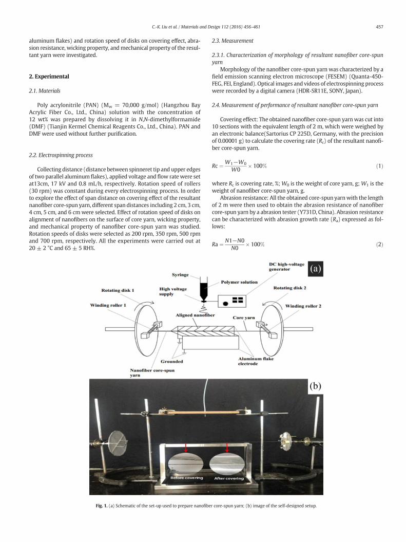
Fig. 1. (a) Schematic of the set-up used to prepare nanofiber core-spun yarn; (b) image of the self-designed setup.
457C.-K. Liu et al. / Materials and Design 112 (2016) 456–461
where Ra is abrasion growth rate, %; N0 is the abrasion cycles of core
yarn, cycle; N1 is the abrasion cycles of nanofiber core-spun yarn, cycle.
Wicking property: Wicking effect (H), defined that when textile
is infiltrated in liquid, some liquid can rise along capillaries due to the
surface tension, was tested by a wicking property tester (YG(B)871,
China). Wicking effect can be expressed as follows:
H ¼
Xn
i¼1
hi
nð3Þ
Fig. 3. (a) nanofiber core-spun yarn fabricated under different span distances (2 cm, 3 cm, 4 cm, 5 cm, 6 cm); (b, c) nanofiber core-spun yarnwith a complete and incomplete covering; (d)
effect of span distance on covering rate and abrasion growth rate of nanofiber core-spun yarn.
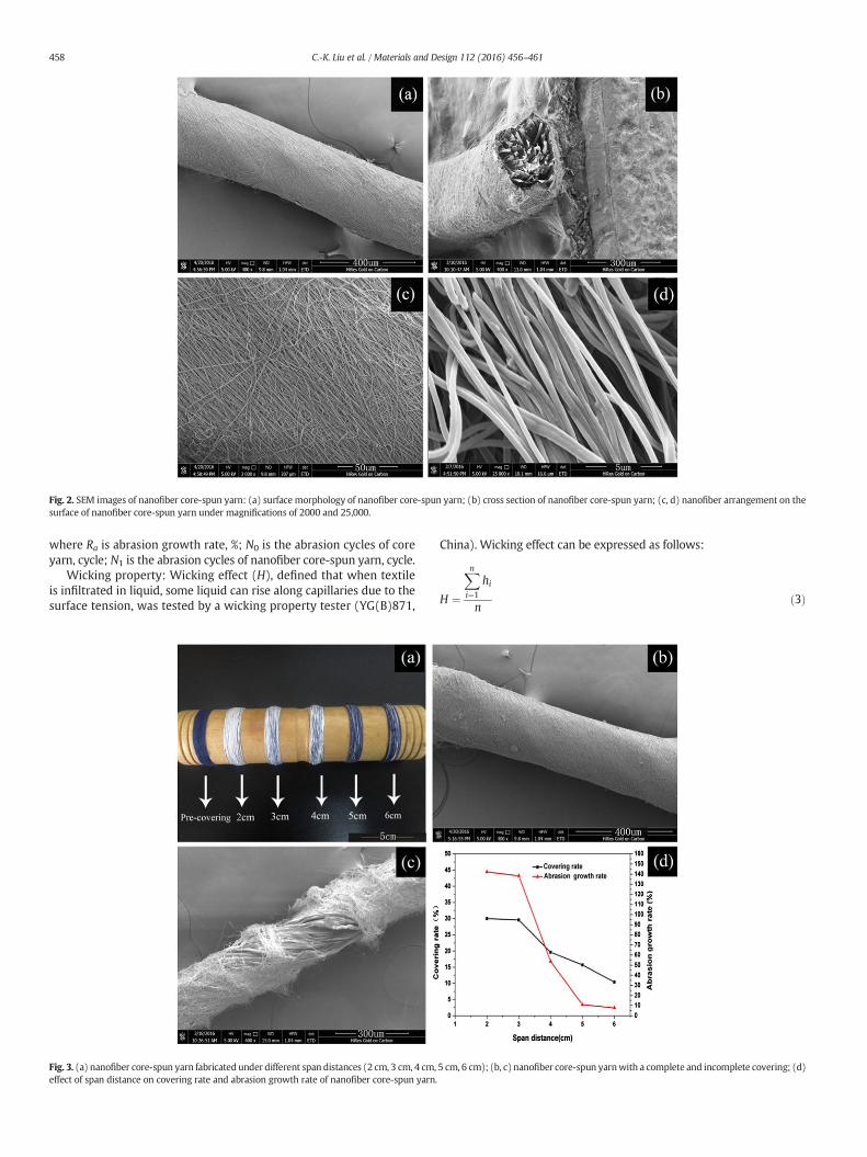
Fig. 2. SEM images of nanofiber core-spun yarn: (a) surface morphology of nanofiber core-spun yarn; (b) cross section of nanofiber core-spun yarn; (c, d) nanofiber arrangement on the
surface of nanofiber core-spun yarn under magnifications of 2000 and 25,000.
458 C.-K. Liu et al. / Materials and Design 112 (2016) 456–461
where H is the mean of wicking effect, cm; hi is the wicking effect of
every nanofiber core-spun yarn, cm; n is the number of nanofiber
core-spun yarn.
Mechanical property: Breaking strengthwasmeasured by a strength
tester (5565, Instron, America).
3. Results and discussion
3.1. Apparatus and mechanism of preparing nanofiber core-spun yarn
The schematic and image of the self-made electrospinning set-up
are shown in Fig. 1, which consists of four major systems: the
electrospinning system (a syringe and a spinneret with the inner diam-
eter of 1.65mm), the applied voltage system (a DC high-voltage gener-
ator), the grounded collecting system (two parallel aluminum flakes),
the covering system (two rotating disks with two winding rollers).
During electrospinning, solution was pushed into spinneret and a
Taylor cone was formed on the spinneret tip. Applied voltage was in-
creased until the jets ejected from Taylor cone, and nanofibers with a
certain degree of orientation would suspend over the edges of two par-
allel aluminum flakes.Meanwhile, two disks began to rotate in the same
direction to make aligned nanofibers cover around the surface of the
core yarn, and two winding rollers also rotated to obtain the resultant
nanofiber core-spun yarn.
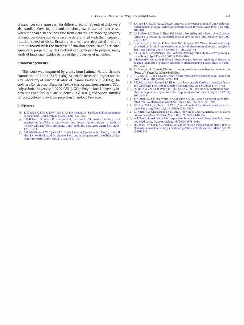
Fig. 5. Alignment direction of nanofibers on the surface of core-pun yarn for different rotation speeds: (a) 200 rpm, (b) 350 rpm, (c) 500 rpm, (d) 700 rpm.
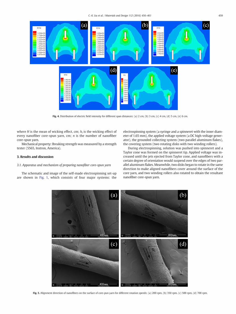
Fig. 4. Distribution of electric field intensity for different span distances: (a) 2 cm, (b) 3 cm, (c) 4 cm, (d) 5 cm, (e) 6 cm.
459C.-K. Liu et al. / Materials and Design 112 (2016) 456–461

3.2. Morphology of the nanofiber core-spun yarn
Although some random fibers could be observed on the surface of
nanofiber core-spun yarn as shown in Fig. 2a, most nanofibers with rel-
atively uniform diameter had a large extent of alignment along a certain
direction (Fig. 2(c, d)). The layered structure could also be observed
through the cross section of nanofiber core-spun yarn shown in Fig. 2b.
3.3. Effect of span distance on covering effect and abrasion resistance of
nanofiber core-spun yarn
Nanofiber core-spun yarns prepared under different span distances
(2 cm, 3 cm, 4 cm, 5 cm, 6 cm) are shown in Fig. 3. Fig. 3a shows that
the covering effect of nanofiber core-spun yarn gradually becomes
poor with the increase of span distance. When the span distance was
2 cm, it could be found that core yarn were covered very well by
electrospun nanofibers. While the covering effect began to deteriorate
when the span distance was more than 5 cm, and only there were few
nanofibers on the surface of core yarn. Fig. 3b and c show the SEM im-
ages of core-spun yarn with a complete and incomplete covering.
From Fig. 3d, it could be discovered that covering rate decreased
from 30.0% to 10.4% when the span distance increased from 2 cm to
6 cm, which is in agreement with the result of Fig. 3a. The reasons can
be attributed as follows: When the span distance becomes larger, the
color between the flake electrodes is becoming from green to blue
shown in Fig. 4, which indicates that electric field intensity of the hori-
zontal component between the two parallel collectors is turning small
and difficult to guide nanofibers span over the gap. Furthermore, the
greater gap also leads to larger gravity of nanofibers. Therefore, nanofi-
bers cannot deposit across the gap smoothly with the increase of span
distance. The maximum covering rate from a single needle was up to
30.0%, while that from 4 needles reported by He [12] was only 70.4%.
In addition, covering effect is the main driving factor for abrasion resis-
tance, so the abrasion growth rate dependent on the covering rate also
became deteriorated with the increase of span distance. The maximum
value of the abrasion growth rate was 142.3% at the span distance of
2 cm.
3.4. Effect of rotation speed of disks on alignment direction of nanofibers on
the surface of nanofiber core-spun yarn
Rotation speed of disks is also the rotation speed of core yarn, differ-
ent rotation speedswill lead to different covering cycles of nanofibers in
a unit of length. So alignment direction of nanofibers on the surface of
core-spun yarn is dependent on rotation speed of disks. SEM images
of nanofiber core-spun yarn for different rotation speeds are shown in
Fig. 5. When rotation speed of disks was 200 rpm, the alignment angle
between direction of nanofibers and axial direction of core yarn was
only 7°, and increasedwith the increase of rotation speed of disks. In ad-
dition, it was observed that nanofibers on surface of core yarn were rel-
atively random when rotation speed was 700 rpm.
3.5. Effect of rotation speed of disks on wicking property of nanofiber core-
spun yarn
Table 1 represents thewicking property of nanofiber core-spun yarn
for different rotation speeds. As shown in the table, wicking property of
nanofiber core-spun yarn for different rotation speeds was better than
that of core yarn. The maximum wicking property of nanofiber core-
spun yarn was 7.6 cm for the rotation speed of 200 rpm, which was en-
hanced by 33% when compared to core yarn. Although the wicking
property for different rotation speeds has a small difference, it still pre-
sents a slight decrease with the increase of rotation speed of disks. The
reasons leading to this result can be explained from the following as-
pects: Firstly, more capillaries formed between nanofibers due to the
nano-sized diameter are beneficial to diffusion of liquid. Secondly, the
alignment angle between direction of nanofibers and axial direction of
core yarn increaseswith the increase of rotation speed,whichwill result
in the inclining of route and bring resistance for diffusion of liquid.
3.6. Effect of rotation speed of disks on mechanical property of nanofiber
core-spun yarn
Fig. 6 gives the breaking strength of the nanofiber core-spun yarn for
different rotation speeds. Breaking strength of the nanofiber core-spun
yarn presented a slight increase compared with the core yarn. With
the increase of rotation speed, breaking strength was decreased first
and then increased. The reasonsmight be given as follows: At a relative-
ly low speed, more aligned nanofibers will be oriented along the axial of
the core yarn, which is beneficial to the increase of breaking strength of
nanofiber core-spun yarn.With the increase of rotation speed, angle be-
tween direction of aligned nanofibers and the axial of core yarn starts to
become smaller and smaller, resulting in a decrease of component force
along the stretching direction. While at a relatively high speed, large
friction and cohesive force between fibers due to the high twist level
can make the nanofiber core-spun yarn withstand larger tension at
break.
4. Conclusion
A novel covering method for preparation of continuous nanofiber
core-spun yarn through electrospinning has been developed. Nanofi-
bers were firstly aligned between the gap of collectors, and then
wound on the surface of core yarn. So more aligned nanofibers deposit-
ed on the surface of core yarn could be obtained through themethod. Ef-
fect of span distance on morphology, covering rate, and abrasion
resistance were analyzed. Wicking property and mechanical propertyFig. 6. Breaking strength of nanofiber core-spun yarn for different rotation speeds.
Table 1
Wicking property of nanofiber core-spun yarn for different rotation speeds.
Rotation speed of disks/rpm Wicking effect (H)/cm
1 2 3 Mean
Core yarn (without covering) 6.1 5.7 5.3 5.7
200 8.8 7.4 6.6 7.6
350 7.8 7.6 6.7 7.4
500 7.4 7.3 6.9 7.2
700 7.4 7.0 7.0 7.1
460 C.-K. Liu et al. / Materials and Design 112 (2016) 456–461
of nanofiber core-spun yarn for different rotation speeds of disks were
also studied. Covering rate and abrasion growth rate both decreased
when the span distance increased from 2 cm to 6 cm.Wicking property
of nanofiber core-spun yarn became deteriorated with the increase of
rotation speed of disks. Breaking strength was decreased first and
then increased with the increase of rotation speed. Nanofiber core-
spun yarn prepared by this method can be hoped to prepare many
kinds of functional textiles by use of the properties of nanofiber.
Acknowledgements
This work was supported by grants from National Natural Science
Foundation of China (51503168), Scientific Research Project for the
Key Laboratory of Functional Fabric of Shannxi Province (13JS035), Dis-
ciplinary Construction Fund for Textile Science and Engineering of Xi'an
Polytechnic University (10709-0821), Xi'an Polytechnic University In-
novation Fund for Graduate Students (CX201601), and Special funding
for postdoctoral innovation project in Shandong Province.
References
[1] T. Subbiah, G.S. Bhat, R.W. Tock, S. Parameswaran, S.S. Ramkumar, Electrospinningof nanofibers, J. Appl. Polym. Sci. 96 (2005) 557–569.
[2] E.D. Boland, G.E. Wnek, D.G. Simpson, K.J. Pawlowski, G.L. Bowlin, Tailoring tissue
engineering scaffolds using electrostatic processing techniques: a study ofpoly(glycolic acid) electrospinning, J. Macromol. Sci., Pure Appl. Chem. 38A (2001)
1231–1243.[3] A.G. MacDiarmid, W.E. Jones, I.D. Norns, J. Gao, A.T. Johnson, N.J. Pinto, J. Hone, B.
Han, F.K. Ko, H. Okuzaki, M. Llaguno, Electrostatically-generated nanofibers of elec-
tronic polymers, Synth. Met. 119 (2001) 27–30.
[4] S.H. Lee, B.C. Ku, X. Wang, Design, synthesis and electrospinning of a novel fluores-
cent polymer for optical sensor applications, Mater. Res. Soc. Symp. Proc. 708 (2002)403–408.
[5] C.J. Buchko, L.C. Chen, Y. Shen, D.C. Martin, Processing and microstructural charac-terization of porous biocompatible protein polymer thin films, Polymer 40 (1999)
7397–7407.[6] E. Kenawy, G.L. Bowlin, K. Mansfield, D.G. Simpson, G.E. Wnek, Release of tetracy-
cline hydrochloride from electrospun poly(ethylene-co-vinylacetate), poly(lactic
acid), and a blend, Contr. J. Release. 81 (2002) 57–64.[7] A.L. Yarin, S. Koombhongse, D.H. Reneker, Bending instability in electrospinning of
nanofibers, J. Appl. Phys. 89 (2001) 3018–3026.[8] D.H. Reneker, A.L. Yarin, H. Fong, S. Koombhongse, Bending instability of electrically
charged liquid jets of polymer solutions in electrospinning, J. Appl. Phys. 87 (2000)
4531–4547.[9] F.L. Scardino, R.J. Balonis, Fibrous structures containing nanofibers and other textile
fibers, USA Patent US/2001/6308509B1.[10] F.L. Zhou, R.H. Gong, I. Nano-coated hybrid yarns using electrospinning, Porat. Surf.
Coat. Technol. 204 (2010) 3459–3463.
[11] F. Dabirian, S.A.H. Ravandi, J.P. Hinestroza, R.A. Abuzade, Conformal coating of yarnsand wires with electrospun nanofibers, Polym. Eng. Sci. 52 (2012) 1724–1732.
[12] J.X. He, Y.M. Zhou, L.D.Wang, R.T. Liu, K. Qi, S.Z. Cui, Fabrication of continuous nano-fiber core-spun yarn by a novel electrospinning method, Fibers Polym. 15 (2014)
2061–2065.[13] Y.M. Zhou, J.X. He, H.B. Wang, K. Qi, B. Ding, S.Z. Cui, Carbon nanofiber yarns fabri-
cated from co-electrospun nanofibers, Mater. Des. 95 (2016) 591–598.
[14] H.Y. Liu, Z.M. Li, K.J. Li, Y. Li, X.W. Li, A novel method for fabrication of fascinatednanofiber yarns, Therm. Sci. 19 (2015) 1331–1335.
[15] S.J. Najafi, A.A. Gharehaghaji, S.M. Etrati, Fabrication and characterization of elastichollow nanofibrous PU yarn, Mater. Des. 99 (2016) 328–334.
[16] W.E. Teo, S. Ramakrishna, Electrospun fiber bundle made of aligned nanofibers over
two fixed points, Nanotechnology 16 (2005) 1878–1884.[17] J.H. Zhao, H.Y. Liu, L. Xu, Preparation and formation mechanism of highly aligned
electrospun nanofibers using a modified parallel electrode method, Mater. Des. 90(2016) 1–6.
461C.-K. Liu et al. / Materials and Design 112 (2016) 456–461