
RESEARCH ARTICLE Jimu LIU, Yuan TIAN, Feng GAO …
14
RESEARCH ARTICLE Jimu LIU, Yuan TIAN, Feng GAO A novel six-legged walking machine tool for in-situ operations © The Author(s) 2020. This article is published with open access at link.springer.com and journal.hep.com.cn Abstract The manufacture and maintenance of large parts in ships, trains, aircrafts, and so on create an increasing demand for mobile machine tools to perform in-situ operations. However, few mobile robots can accommodate the complex environment of industrial plants while performing machining tasks. This study proposes a novel six-legged walking machine tool consisting of a legged mobile robot and a portable parallel kinematic machine tool. The kinematic model of the entire system is presented, and the workspace of different components, including a leg, the body, and the head, is analyzed. A hierarchical motion planning scheme is proposed to take advantage of the large workspace of the legged mobile platform and the high precision of the parallel machine tool. The repeatability of the head motion, body motion, and walking distance is evaluated through experiments, which is 0.11, 1.0, and 3.4 mm, respectively. Finally, an application scenario is shown in which the walking machine tool steps successfully over a 250 mm- high obstacle and drills a hole in an aluminum plate. The experiments prove the rationality of the hierarchical motion planning scheme and demonstrate the extensive potential of the walking machine tool for in-situ operations on large parts. Keywords legged robot, parallel mechanism, mobile machine tool, in-situ machining 1 Introduction An increasing demand for manufacturing and maintaining large parts in several industrial fields, such as aeronautics, railroad, shipping, offshore platforms, and power plants, has emerged. Traditionally, large parts are generally machined by large workspace machines [1]. In terms of maintenance and repair, a conventional approach involves disassembling the damaged parts of a system and shipping them to specialized workshops for processing, which is costly, complex, and time consuming. Furthermore, certain situations involve damaged parts that are impossible to disassemble; thus, maintenance relies on human work- force. Therefore, portable or mobile machine tools for performing in-situ post-production tasks for large parts are in demand. Mobile manipulators have been studied for decades. The mobility of a manipulator can be provided by linear guide ways, wheeled or tracked vehicles, or legged robots. One of the most common mobile manipulators is a classical serial robot arm mounted on a wheeled mobile base [2]. MADAR is a dual-arm mobile manipulator with two commercial UR5 arms mounted on an omnidirectional platform. The mobile platform is driven by three specially designed omni-wheels that differ from commonly used Mecanum wheels [3]. KUKA AG demonstrated the polishing application of the mobile KMR QUANTEC robot in the aerospace industry. Apart from wheeled mobile platforms, parallel kinematic machine (PKM) tools are often mounted on gantry or crane support machines to perform material removal tasks, thereby combining the advantages of large travel ranges and high stiffness [4,5]. A track-based serial kinematic robot named SCOMPI was designed to perform in-situ processes, such as gouging, welding, grinding, hammer peening, and post-weld heat treating, for hydroelectric turbine maintenance. The track could be straight, circular, or a piece-wise sequence of circular track sections [6,7]. Moreover, a few mobile machines use a large-scale workpiece as a supporting structure. Several crawling portable robots have been designed to attach to fuselage or wing sections [8,9]. The Intersector Welding Robot was developed to conduct welding and machining processes while moving along rails mounted on the inner surface of the International Thermo- nuclear Experimental Reactor vacuum vessel sector [10]. Legged mobile robots are superior to wheeled and tracked robots in terms of terrain adaptability, as they can deal with isolated footholds and discontinuous terrains, Received January 8, 2020; accepted April 23, 2020 Jimu LIU, Yuan TIAN, Feng GAO (✉) State Key Laboratory of Mechanical System and Vibration, School of Mechanical Engineering, Shanghai Jiao Tong University, Shanghai 200240, China E-mail: [email protected] Front. Mech. Eng. 2020, 15(3): 351–364 https://doi.org/10.1007/s11465-020-0594-2
Transcript of RESEARCH ARTICLE Jimu LIU, Yuan TIAN, Feng GAO …

RESEARCH ARTICLE
Jimu LIU, Yuan TIAN, Feng GAO
A novel six-legged walking machine tool for in-situ operations
© The Author(s) 2020. This article is published with open access at link.springer.com and journal.hep.com.cn
Abstract The manufacture and maintenance of largeparts in ships, trains, aircrafts, and so on create anincreasing demand for mobile machine tools to performin-situ operations. However, few mobile robots canaccommodate the complex environment of industrialplants while performing machining tasks. This studyproposes a novel six-legged walking machine toolconsisting of a legged mobile robot and a portable parallelkinematic machine tool. The kinematic model of the entiresystem is presented, and the workspace of differentcomponents, including a leg, the body, and the head, isanalyzed. A hierarchical motion planning scheme isproposed to take advantage of the large workspace of thelegged mobile platform and the high precision of theparallel machine tool. The repeatability of the head motion,body motion, and walking distance is evaluated throughexperiments, which is 0.11, 1.0, and 3.4 mm, respectively.Finally, an application scenario is shown in which thewalking machine tool steps successfully over a 250 mm-high obstacle and drills a hole in an aluminum plate. Theexperiments prove the rationality of the hierarchicalmotion planning scheme and demonstrate the extensivepotential of the walking machine tool for in-situ operationson large parts.
Keywords legged robot, parallel mechanism, mobilemachine tool, in-situ machining
1 Introduction
An increasing demand for manufacturing and maintaininglarge parts in several industrial fields, such as aeronautics,railroad, shipping, offshore platforms, and power plants,has emerged. Traditionally, large parts are generally
machined by large workspace machines [1]. In terms ofmaintenance and repair, a conventional approach involvesdisassembling the damaged parts of a system and shippingthem to specialized workshops for processing, which iscostly, complex, and time consuming. Furthermore, certainsituations involve damaged parts that are impossible todisassemble; thus, maintenance relies on human work-force. Therefore, portable or mobile machine tools forperforming in-situ post-production tasks for large parts arein demand.Mobile manipulators have been studied for decades. The
mobility of a manipulator can be provided by linear guideways, wheeled or tracked vehicles, or legged robots. Oneof the most common mobile manipulators is a classicalserial robot arm mounted on a wheeled mobile base [2].MADAR is a dual-arm mobile manipulator with twocommercial UR5 arms mounted on an omnidirectionalplatform. The mobile platform is driven by three speciallydesigned omni-wheels that differ from commonly usedMecanum wheels [3]. KUKA AG demonstrated thepolishing application of the mobile KMR QUANTECrobot in the aerospace industry. Apart from wheeledmobile platforms, parallel kinematic machine (PKM) toolsare often mounted on gantry or crane support machines toperform material removal tasks, thereby combining theadvantages of large travel ranges and high stiffness [4,5]. Atrack-based serial kinematic robot named SCOMPI wasdesigned to perform in-situ processes, such as gouging,welding, grinding, hammer peening, and post-weld heattreating, for hydroelectric turbine maintenance. The trackcould be straight, circular, or a piece-wise sequence ofcircular track sections [6,7]. Moreover, a few mobilemachines use a large-scale workpiece as a supportingstructure. Several crawling portable robots have beendesigned to attach to fuselage or wing sections [8,9]. TheIntersector Welding Robot was developed to conductwelding and machining processes while moving along railsmounted on the inner surface of the International Thermo-nuclear Experimental Reactor vacuum vessel sector [10].Legged mobile robots are superior to wheeled and
tracked robots in terms of terrain adaptability, as they candeal with isolated footholds and discontinuous terrains,
Received January 8, 2020; accepted April 23, 2020
Jimu LIU, Yuan TIAN, Feng GAO (✉)State Key Laboratory of Mechanical System and Vibration, School ofMechanical Engineering, Shanghai Jiao Tong University, Shanghai200240, ChinaE-mail: [email protected]
Front. Mech. Eng. 2020, 15(3): 351–364https://doi.org/10.1007/s11465-020-0594-2

such as stairs. A hydraulically driven six-legged robotnamed COMET-IV was developed to detect landmines andperform rescues in disaster areas [11]. Similarly, a motor-driven six-legged robot named SILO6 was designed todetect and remove antipersonnel landmines in infestedfields [12]. CENTAURO is a wheeled-legged mobilemanipulation platform capable of executing demandingmanipulation tasks in disaster-response scenarios [13].However, owing to the complexity of their mechanism andcontrol as well as low stiffness, legged robots are rarelyused in the industrial field. Only a limited number oflegged robots have been developed for machiningapplications. Yang et al. [14] proposed an industry-oriented tripod robot that combines the mobility of leggedrobots and the advantages of parallel mechanisms. Withlockers on certain passive joints and clamping devices atthe end of limbs, the robot used only six actuators toperform locomotion tasks and manipulation tasks.REMORA is a reconfigurable quadruped robot with thesame design philosophy [15]. Unlike the two aforemen-tioned robots, which remain in the conceptual designstage, a robotic walking machine tool prototype namedWalkingHex has been developed, and a set of experimentshave shown its ability to perform in-situ machiningoperations [16,17]. The robot is a Stewart–Gough platformwithout a base platform that can perform machining taskswith all six feet attached to the floor. The top sphericaljoints of the robot can be actuated for the walking phase.However, the three-wire actuated spherical joint lacks anautomated zeroing method and high motion accuracy.Hence, a calibration process, which takes approximately10 min, is necessary when transitioning from the walkingphase to the machining phase.In terms of the kinematic design of manipulators,
articulated arms are widely used. However, the lowstiffness and precision of serial robot arms limit theirapplication in light processing, such as welding, painting,and inspections. Therefore, PKMs for mobile machininghave garnered increasing attention. Similar to the well-known Sprint Z3 head, a 3-degree of freedom (3-DOF)PKM module called the A3 head has been designed forlarge structural component machining [18]. Moreover, thedynamics and positional capability of the Fanuc F200iBhexapod robot have been investigated for mobile machin-ing [19,20]. Another portable large-volume machine toolsolution is the hybrid serial-parallel mechanism. A typicalexample is the Tricept machine, which has been success-fully utilized in the aerospace industry [4]. Inspired by theTricept, Huang et al. [21] designed a 4-DOF hybridkinematic machine named Bicept comprising a 2-DOFparallel mechanism and a 2-DOF rotating head. Bicept wasdesigned as a machine module moving along a long trackfor drilling and riveting in the assembly process of aircraftstructural components. The high stiffness and precisionadvantages of parallel or hybrid-parallel kinematic
machine tools make them promising solutions for in-situmachining.In this study, we introduce a novel six-legged walking
machine tool developed to perform in-situmaintenance forlarge parts, such as trains, ships, and airplanes. Workingenvironments may include certain obstacles or uneventerrain. Therefore, the walking machine tool is expected todemonstrate the following abilities: Can walk autono-mously to a working area; can adapt to different types ofterrain, including flats, slopes, and steps; and can performmachining operations on large parts. Its overall layout issimilar to that of a classic mobile manipulator, that is, arobotic manipulator on a mobile platform. Our machinediffers from classic mobile manipulators because it uses a6-DOF PKM as a manipulator and a six-parallel-leggedrobot as a mobile platform. The upper PKM features highstiffness and high precision, which are crucial formachining tasks. Meanwhile, the lower legged robotprovides a system with higher mobility and betteradaptability for locomotion tasks compared with wheeledor tracked vehicles. Moreover, the parallel kinematic legarchitecture allows the lower legged robot to overcome thedisadvantages of low payload and low rigidity, which arecommon in most legged robots. In contrast to WalkingHex,our proposed walking machine tool has a complete PKMmodule; hence, the kinematic calibration process beforeevery machining task is unnecessary. In addition, each legof the lower legged robot is actuated by three ball screws,thereby providing the leg with high payload and highaccuracy during the walking phase.The rest of this paper is organized as follows. The
overall description of the walking machine tool ispresented in Section 2. Kinematic models of the leg,body, and head are described, and the workspace of thethree components is analyzed in Section 3. A hierarchicalmotion planning scheme with simulations is proposed inSection 4, and two experiments are performed in Section 5.The first experiment measures the repeatability of the threemotion layers, and the second experiment demonstrates anapplication scenario combining the three motion layers.Finally, conclusions are provided in Section 6.
2 System overview
2.1 Design concept
The main design objective of the six-legged walkingmachine tool is to provide high accuracy for a PKM tooland maintain the locomotivity of a legged robot. Mobileprocessing applications require mobile machine tools withhigh precision, high rigidity, and high payload. Ourlaboratory designed a six-legged walking robot with athree-limb parallel mechanism for its leg design. The novellegs allow the robot to carry a payload of 200 kg [22]. A
352 Front. Mech. Eng. 2020, 15(3): 351–364

late-generation version of this robot was utilized toperform low-precision tasks, such as opening doors [23]and turning valves [24]. However, the body motionaccuracy of the legged robot failed to satisfy machiningrequirements. Therefore, a manipulator is mounted on thebody of the six-legged robot to conduct high-precisiontasks.For versatility, the manipulator is expected to have six
DOFs. In addition, parallel kinematic manipulators arepreferred owing to their superiority in terms of precision,rigidity, and payload compared with serial manipulators.The most common mechanisms that meet the aboveconditions are the 6-universal-prismatic-spherical (6-UPS), which is known as the Stewart platform, and the6-prismati-universalc-spherical (6-PUS), which is alsocalled the Hexaslide [25]. The latter has an advantage insmall moving inertia and fast dynamic response, becauseits actuators are all mounted on a fixed base. Moreover,fixed mounting type actuators are convenient for cablerouting. Therefore, a 6-PUS parallel mechanism is chosento design the mobile manipulator mounted on the body.
2.2 Mechanical description
A physical prototype of the six-legged mobile machinetool is shown in Fig. 1. From a topology perspective, themobile machine tool consists of seven parallel mechan-isms, namely, six legs and a PKM head. These mechanismsare mounted on a single base, that is, the body. The overalldimension of the walking machine tool is shown in Fig. 2.The walking machine tool is 1685 mm wide, 1295 mmlong, and 1362 mm high.
1) Leg. A 1-UP and 2-UPS parallel mechanism isemployed for the leg design. In this notation, U representsa passive universal joint, P denotes an active prismaticjoint, and S stands for a passive spherical joint. The activeprismatic joint is embodied by an originally designed
linear actuator driven by a direct current (DC) servo motorthrough a gear box, a synchronous belt, and a ball screw.The three chains are connected to a triangle base plate withuniversal joints. A small triangle structural component,which is considered as the ankle of the leg, is fixed at theend of the UP chain piston rod. The piston rods of the UPSchains are connected to the ankle by spherical joints. A 6-DOF force/torque sensor is mounted under the ankle, andanother passive spherical joint connecting the foot ismounted on the other side of the sensor.2) Body. The robot body consists of two aluminum
plates connected by steel ribs. The body is designed to beas compact as possible while providing adequate mountingspace for the legs and PKM head. The six legs aresymmetrically arranged under the body. The PKM head ismounted on the front of the body, and the control box andlithium batteries are mounted on the back, thereby makingthe weight distributed in equilibrium. The structural frameof the PKM head can increase the rigidity of the body. Thecontrol box contains the controllers and servo drives.3) Head. The architecture of the robot head is a 6-PUS
parallel mechanism. Six linear actuators are mounted on ahexagonal prismatic frame. The slider on each linearactuator is driven by a DC motor through a ball screw. Amoving platform housing an electric spindle is connectedto all the sliders by six links. Each link has two universaljoints on both sides. Moreover, each link consists of twocoaxial rods with a revolute joint in between. The axis ofrevolution goes through the universal joint centers. Forbrevity, the function of one universal joint and the revolutejoint is equivalent to that of a spherical joint.
2.3 Control architecture
The control architecture of the walking machine tool isillustrated in Fig. 3. It consists of two controllers: (a) Thelocomotion controller running a self-developed leggedrobot control program on top of Linux with a real-timeinfrastructure named Xenomai, controlling 18 DC motorsof the legged mobile platform; and (b) the manipulationcontroller running Beckhoff TwinCAT3 on top ofWindows 10, controlling six DC motors of the PKMhead. All the servo drives are connected to the controllersthrough the EtherCAT real-time network. The locomotioncontroller is the main controller, receiving commands fromthe remote terminal and giving commands to themanipulation controller. Two Microsoft Kinect visionsensors are mounted on the left and right sides of thebody and connected to the locomotion controller through aUSB interface. The sensors are utilized for autonomousobstacle avoidance. A Creative BlasterX Senz3D depth-sensing camera is mounted on the spindle platform andconnected to the manipulation controller. The camera isemployed to locate a workpiece with respect to the mobilemachine tool. The camera also provides an image signalfor the visual servo processing task.
Fig. 1 Physical prototype of the six-legged walking machinetool.
Jimu LIU et al. A novel six-legged walking machine tool for in-situ operations 353

2.4 Motion layers
A hierarchical motion planning scheme is proposed to takeadvantage of the large workspace of the legged mobileplatform and the high precision of the PKM head, as shownin Fig. 4. The walking machine tool involves 24 actuations,which presents a motion planning challenge. Hence, wedivide the motion of the system into three layers based onthe moving subjects. The leg motion layer is utilized to
execute the walking task and to lead the machine tool to thetarget position. This layer has the largest working range butthe lowest precision. The body motion layer is used toadjust the pose of the body, bring the PKM head near aworkpiece, or expand the working range of the PKM head.This layer has an intermediate working range andintermediate precision. The head motion layer is employedto execute the machining task. This layer has the smallestworking range but the highest precision.
Fig. 3 Control architecture of the walking machine tool.
Fig. 2 Dimensions of the front and side views of the walking machine tool.
354 Front. Mech. Eng. 2020, 15(3): 351–364

3 Kinematic model and workspace analysis
3.1 Inverse kinematics
First, we need to derive the inverse kinematic solution of asingle leg. The schematic diagram of the leg mechanism isshown in Fig. 5. In a coordinate frame, the red, green, andblue arrows indicate the x, y, and z axes, respectively. Thisnotation is also used in other figures in this paper. Thecenters of the universal joints and spherical joints aredenoted by Uji and Sji, respectively, where the subscript iði ¼ 1, 2, :::, 6Þ is the leg index, and the subscript j is thechain index ( j ¼ 1 for the UP chain, and j ¼ 2 and 3 forthe UPS chains). The foot is connected to the UP chainwith another passive spherical joint whose center isdenoted by Sfi. Sfi is also used as the end-effector centerpoint for the motion planning of the leg mechanism.A reference frame fHig, which stands for the hip frame,
is fixed to the triangle base plate, while the origin OHi iscoincident with U1i. Its x axis is perpendicular to the plane
U1iU2iU3i, while its z axis is parallel to the vectorU3iU2i
↕ ↓
. Amoving frame fAig, which represents the ankle frame, isattached to the piston rod of the UP chain. Its x axis iscoincident with the prismatic joint axis of the UP chain,which goes through OHi. Its yz plane goes through S2i, and
its z axis is parallel to the vector S3iS2i↕ ↓
. Thus, its origin OAican be derived. The joint coordinates of the parallel leg
mechanism are the lengths of each chain. The specificdefinitions are shown in the following equations:
l1i ¼ kU1iOAik, (1)
l2i ¼ kU2iS2ik, (2)
l3i ¼ kU3iS3ik: (3)
Fig. 4 Three motion layers of the walking machine tool.
Fig. 5 Schematic diagram of the parallel leg mechanism.
Jimu LIU et al. A novel six-legged walking machine tool for in-situ operations 355

The inverse kinematics of the 1-UP and 2-UPS parallelmechanism is to calculate the joint coordinates given theCartesian coordinates of Sfi with respect to the hip framefHig. It can be derived based on the vector loop method.The vector loop OHiOAiSfiOHi is considered to calculate thegeneralized coordinates of the UP chain:
HiSfi ¼ HiAiT $AiSfi , (4)
where HiSfi ¼ ½xi yi zi�T are the input variables of the
inverse kinematics, and AiSfi ¼ ½Sfxi Sfyi Sfzi�T are given asthe kinematic parameters. In this notation, the pre-super-script Hi in the symbol HiSfi indicates that the vector isexpressed relative to the frame fHig, and so on. And thehomogeneous transformation matrix Hi
AiT serves as thedescription of frame fAig relative to fHig. According tothe definition of the ankle frame fAig and UP chainstructure, HiAiT is determined by the two rotation angles ofthe universal joint and the displacement of the prismaticjoint:
HiAiT ¼
cα1icβ1i – cα1isβ1i sα1i l1icα1icβ1i
sβ1i cβ1i 0 l1isβ1i
– sα1icβ1i sα1isβ1i cα1i – l1isα1icβ1i
0 0 0 1
266664
377775,
(5)
where α1i and β1i are the first and second rotation angle ofthe universal joint in the UP chain, respectively, and sα1i isthe shorthand for sinα1i, cα1i is the shorthand for cosα1i,and so on.By combining Eqs. (4) and (5), the generalized
coordinates of the UP chain can be calculated as follows:
l1i ¼ffiffiffiffiffiffiffiffiffiffiffiffiffiffiffiffiffiffiffiffiffiffiffiffiffiffiffiffiffiffiffiffiffiffiffiffiffiffiffiffiffiffiffiffix2i þ y2i þ z2i – S
2fyi – S
2fzi
q– Sfxi, (6)
β1i ¼ arcsinyiffiffiffiffiffiffiffiffiffiffiffiffiffiffiffiffiffiffiffiffiffiffiffiffiffiffiffiffiffiffiffiffiffi
ðl1i þ SfxiÞ2þS2fyi
q – arcsinSfxiffiffiffiffiffiffiffiffiffiffiffiffiffiffiffiffiffiffiffiffiffiffiffiffiffiffiffiffiffiffiffiffiffi
ðl1i þ SfxiÞ2þS2fyi
q ,
(7)
α1i ¼ arctanSfxixi – ½ðl1i þ SfxiÞcβ1i – Sfyicβ1i�zi½ðl1i þ SfxiÞcβ1i – Sfyisβ1i�xi þ Sfzizi
: (8)
Hence, HiAiT is obtained by substituting Eqs. (6)–(8) intoEq. (5). The lengths of UPS chains l2i and l3i can becalculated as follows:
l2i ¼ kHiAiT $AiS2i –HiU2ik, (9)
l3i ¼ kHiAiT $AiS3i –HiU3ik, (10)
where HiU2i andHiU3i respectively stand for the positions
of U2i and U3i with respect to the frame fHig.Thus, the relationship between HiSfi and the joint
coordinates is derived:
qi ¼ l1i l2i l3i½ �T: (11)
Next, we need to express the leg kinematic model in thebody frame. All six legs are symmetrically distributedaround the body frame fBg, as shown in Fig. 6. The baseplate of each leg is fixed under the body structure; hence,the pose of frame fHig relative to fBg is constant.Generally, motion planning for legged robots is imple-mented in two ways, that is, either planning foot-tippositions relative to the body frame or planning the bodypose and foot-tip positions simultaneously with respect tothe ground frame fGg. The second method can beconverted to the first method by applying a matrixtransformation:
BSfi ¼ GBT
–1 $GSfi , (12)
where GBT is the homogeneous transformation matrix
representing the body pose with respect to frame fGg, BSfi
and GSfi respectively denote the positions of foot-tip Sfiwith respect to frame fBg and frame fGg. Thus, we need toexpress the inverse kinematics of the leg mechanism in thebody frame.
The description of the ith hip frame fHig with respect tothe body frame fBg is expressed as follows:
BHiT ¼
BHiR
BpHi
0 1
" #, (13)
where BpHi ¼ ½Hxi Hyi Hzi�T is the origin position of fHigwith respect to fBg, and the rotation matrix B
HiR isexpressed by ZXZ-Euler angles φi �i ψi½ �T.
Fig. 6 Definition of coordinate systems in the legged mobileplatform.
356 Front. Mech. Eng. 2020, 15(3): 351–364

BHiR ¼ RzðφiÞRxð�iÞRzðψiÞ, (14)
where RzðφiÞ is a rotation matrix that represents a rotationabout z axis by φi degrees, and so on.While planning the trajectory of the legged mobile
platform, the body pose and all foot-tip locations withrespect to the ground frame are given simultaneously.
HiSfi ¼ BHiT
–1 $BSfi : (15)
Hence, we can use Eqs. (6), (9), and (10) for each leg tocalculate all 18 joint variables in the legged mobileplatform.Finally, we derive the inverse kinematics of the 6-PUS
machine head. The mechanism schematic is shown inFig. 7. Ak and Bk represent the rotation centers of thespherical joint and the universal joint in the kth chain,respectively; Bk0 is the initial position of Bk when theactuators are on their home position; and ek represents theunit direction vector of the kth prismatic joint. Therefore,the input variables are the distances between Bk and Bk0. Amoving frame fPg is attached to the spindle platform. Itsorigin is located in the center of the hexagonA1A2A3A4A5A6. Its z axis is perpendicular to the hexagon
plane, while its x axis is parallel to the vector A2A1
↕ ↓
. Its yaxis is derived by the right-hand rule. A reference framefMg is attached to the machine casing and coincident withfPg when all the prismatic joints are in their homeposition.
For the kth kinematic chain, according to the vector loopmethod, we have
MPP þ MP R$Pak ¼ Mb0k þ qkek þ M lk , (16)
where MpP stands for the origin location vector of fPgwith respect to fMg, M
P R is a rotation matrix describing
fPg relative to fMg, Pak stands for the location of the kthuniversal joint center Sk with respect to the movingplatform frame fPg, Mb0k represents the location of U0k
with respect to the machine frame fMg, lk ¼ BkAk
↕ ↓
, and qkis the kth joint coordinate.For brevity, we define
hk ¼ MpP þ MP R$Pak –
Mb0k : (17)
Hence,
lk ¼ hk – qkek : (18)
By squaring both sides of the equation above, we obtain
L2k ¼ hTkhk – 2qkhTk ek þ q2k : (19)
Two solutions exist for a quadratic equation, but onlyone of the solutions satisfies the continuity conditionconsidering the initial position of the slider.
qk ¼ hTk ek –ffiffiffiffiffiffiffiffiffiffiffiffiffiffiffiffiffiffiffiffiffiffiffiffiffiffiffiffiffiffiffiffiffiffiffiffiffiffiffiðhTk ekÞ2 – hTkhk þ L2k
q: (20)
The joint coordinates are calculated by applying Eq. (20)to all six chains.
q ¼ q1 q2 � � � q6½ �T: (21)
3.2 Workspace analysis
In this section, we analyze the workspace of three differentcomponents, including a single leg, the body, and the PKMhead.The workspace of the leg mechanism can be obtained
with the discretization method. The workspace of a singleleg is searched by discretizing the Cartesian coordinates ofthe foot-tip, applying inverse kinematics, and checkingjoint variable limits, as follows:
ljmin£lj£ljmax,
cosα1cosβ1£cos�m,j ¼ 1, 2, 3,
((22)
where �m is the maximum tilt angle of the universal joint inthe UP chain.The workspace boundary with respect to the body frame
is shown in Fig. 8(a). A red cylinder is drawn within theworkspace to visually represent the range of the foot-tipmotion when the mobile platform walks. The cylinder’sdiameter represents the maximum walking step length, andits height indicates the corresponding step height. Themaximum height of the cylinder is 0.12 m when itsdiameter is set to 0.8 m. When the diameter is reduced to0.4 m, the height can reach up to 0.25 m. The cylinder ismeaningful for choosing the proper walking step para-meters.With all the feet fixed on the ground, the body can
function as a redundantly actuated 6-DOF platform. The
Fig. 7 Schematic diagram of the PKM head.
Jimu LIU et al. A novel six-legged walking machine tool for in-situ operations 357

body workspace can be determined by discretizing thebody pose parameters and checking the boundary condi-tions with Eq. (22) for all six legs.The PKM head workspace can also be calculated using
the same methods. The constraint conditions are the sixjoint variable range limits.
qkmin£qk£qkmax, k ¼ 1, 2, :::, 6: (23)
The translational workspace of the body and PKM headis shown in Figs. 8(b) and 8(c), respectively. We draw amaximal cube within each working envelope. The cubesare utilized to generate testing poses for the performanceevaluation according to the ISO 9283:1998 ManipulatingIndustrial Robots—Performance Criteria and RelatedTest Methods standards [26]. Furthermore, the cubes canintuitively represent the size of the workspace. The cube inthe body workspace has an edge length of 0.25 m, whereasthe cube in the head workspace has an edge length of 0.075m. Obviously, the working range of the PKM head is muchsmaller than that of the body.
4 Hierarchical motion planning andsimulation
4.1 General workflow
A general workflow combing the three motion layers toperform a processing task is shown in Fig. 9. First, therobot is navigated to a workpiece from an initial positionusing the bottom motion layer. Second, the body adjusts itspose to locate the PKM head in a proper position using themiddle motion layer. Finally, the PKM head deals with themachining tasks using the top motion layer.
4.2 Leg motion layer
Various walking gaits can be applied to a six-legged robot.Among them, the tripod gait is the most efficient forplanning. The legs are numbered, as shown in Fig. 6. Thefirst, third, and fifth legs are divided into the first group,and the rest of the legs are divided into the second group.When one group of legs is swinging, the other group of
legs stands on the ground supporting the body. Using thetripod gait, the robot can walk in any direction and turn onthe horizontal plane.A typical forward-walking gait with two cycles is
demonstrated in Fig. 10, where d and h stand for the steplength and step height, respectively, and T represents awalking cycle. Each cycle consists of two steps, and eachstep takes a half cycle. According to Figs. 10(a) and 10(b),during the first half cycle, the first group of legs swingsforward with a distance of 0:5d, while the second group oflegs stands on the ground. The swing trajectory of eachfoot with respect to the ground frame is a semi-ellipsecurve. Similarly, in the final half cycle, the second group oflegs steps forward 0:5d. During the period in between,each group swings alternately every half cycle with adistance of d. Correspondingly, the body motion can bedivided into three phases, namely, the accelerated motionphase, the uniform motion phase, and the deceleratedmotion phase. From 0 to 0:5T , the body accelerates to thetarget speed d=T and maintains the speed during the nextcycle. In the final half cycle, that is, from 1:5T to 2T , thebody decelerates from the velocity to stop. The feettrajectories with respect to the body frame are shown inFig. 10(c). This walking gait can be generalized easily toadditional cycles. The number of walking cycles is denotedby n. Leg motions between 0:5T and 1:5T are repeatedn – 1 times, and the overall walking distance is ðn – 0:5Þd.A simulation intuitively demonstrates the walking
motion of the mobile machine tool, as shown in Fig. 11.The captures show the leg configurations every half cycle.
4.3 Body motion layer
As analyzed in Section 3.2, the workspace of the PKMhead is extremely limited. Therefore, we need to use thebody motion layer to extend the working range of the toolcenter point (TCP). This layer is employed when all sixfeet are standing on the ground, thereby making it moreaccurate than the walking motion. Support from multiplelegs also leads to higher stiffness compared with locomo-tion via alternating legs. The purpose of this level is toconvey the PKM head to its preferable posture relative tothe processing area in a large workpiece. As illustrated in
Fig. 8 Workspace of different components of the walking machine tool. (a) Leg; (b) body; (c) head.
358 Front. Mech. Eng. 2020, 15(3): 351–364

Fig. 9 Workflow of the walking machine tool for performing mobile machining tasks.
Fig. 10 Feet trajectories in two walking cycles. (a) Horizontal and (b) vertical displacements of feet and body; (c) feet trajectories withrespect to the body frame.
Jimu LIU et al. A novel six-legged walking machine tool for in-situ operations 359

Fig. 12, multiple support legs enable the robot body toengage in flexible behaviors.The body pose adjustment uses point-to-point motion in
a six-dimensional space. We interpolate the pose para-meters with cubic splines, with position and velocityvalues specified at the beginning and ending moments.
4.4 Head motion layer
The head motion presents the highest precision of thesystem, thereby satisfying industrial requirements. ThePKM head is designed to include all six spatial DOFs(Fig. 13). Hence, it can adapt its pose to curved workingsurfaces. In the machining process, the first step is toconstruct the workpiece coordinate frame fWg byscanning the workpiece feature using the vision sensoron the PKM head or an external positioning device. Inaddition, M
WT , which is the relationship between themachine frame fMg and the workpiece frame fWg, isdetermined. Besides, the TCP position offset with respectto the spindle platform frame fPg must be measured toobtain the pose of the tool frame fTg relative to fPg,which is denoted by P
TT . The machining process isperformed by planning the motion of the tool frame fTgrelative to the workpiece frame fWg, namely, W
T T . Thepath of W
T T can be preprogrammed tool paths or sensor-based online-generated paths. W
T T can be expressed as a
product of transformations in two different ways, whichconstructs a transform equation:
MP T $PTT ¼ M
WT $WT T : (24)
Thus, the path of WT T can be transferred to the path of
MP T , that is, the relative pose between the spindle platformframe and the machine frame.
MP T ¼ M
WT $WT T $PTT–1 : (25)
The head motion trajectories are generated by combin-ing Eq. (25) with the inverse kinematics of the PKM head.
5 Experiment
5.1 Repeatability test
The repeatability of the three motion layers was testedbased on ISO 9283 standards [26]. A Leica AT960 lasertracker (Fig. 14(a)) was used as the measurementequipment. The spindle was removed from the PKMhead and replaced with a calibration plate with threemagnetic nests to hold the spherically mounted retro-reflector (SMR; Fig. 14(b)).The repeatability test (Fig. 14) of the leg motion layer
was performed by commanding the legged mobile plat-form to walk forward and backward for 30 cycles and
Fig. 11 Snapshots of the walking simulation.
Fig. 12 Snapshots of the body twisting simulation.
Fig. 13 Snapshots of the PKM head twisting simulation.
360 Front. Mech. Eng. 2020, 15(3): 351–364

using a laser tracker to measure the body displacements.The PKM head was disabled and kept still during thewalking motion. Therefore, the displacement of the SMRon the head could represent the body displacement. Therepeatability of the walking motion was affected by notonly the inherent accuracy of the legged robot but also theroughness of the ground. The positioning error of thewalking motion accumulated as the cycle increased. Thus,
we used the walking distance error to represent the walkingmotion repeatability. The test was performed with differentwalking steps from one to three, and the result is shown inFig. 15(a).The repeatability test of the body motion was performed
by commanding the body to move to five target poses for30 cycles. As shown in Fig. 14(c), the commanded poseswere arranged in the largest available cube at the center of
Fig. 14 Experiment setup of the repeatability test. (a) Overall setup; (b) SMR holders on the moving platform; (c) commanded poses.
Fig. 15 Repeatability test results of different motion layers. (a) Walking; (b) body motion; (c) head motion.
Jimu LIU et al. A novel six-legged walking machine tool for in-situ operations 361
the working volume and offset by 10% of the diagonaldistance. The head motion repeatability was tested in thesame way for 30 cycles, with all leg actuators locked. Thepose repeatability is defined as follows:
RPl ¼ l þ 3Sl, (26)
l ¼ 1
n
Xnj¼1
lj, (27)
li ¼ffiffiffiffiffiffiffiffiffiffiffiffiffiffiffiffiffiffiffiffiffiffiffiffiffiffiffiffiffiffiffiffiffiffiffiffiffiffiffiffiffiffiffiffiffiffiffiffiffiffiffiffiffiffiffiffiffixi – xð Þ2 þ yi – yð Þ2 þ zi – zð Þ2
q, (28)
Sl ¼
ffiffiffiffiffiffiffiffiffiffiffiffiffiffiffiffiffiffiffiffiffiXnj¼1
lj – l� �n – 1
vuuuut, (29)
where RPl is the pose repeatability, l and Sl are the meanvalue and standard deviation of the position error,respectively, and lj is the distance between the jth measuredcoordinates and the mean values. The pose repeatability ofeach target pose was calculated by applying Eqs. (26)–(29)to the measured poses. The maximum value of the five-pose repeatability was taken as the motion repeatability.The results are presented in Fig. 15 in term of boxplots.
The repeatability of the head motion was 0.11 mm and thatof the body motion was 1.0 mm. This finding proved thatthe head motion was more precise than the body motion.The walking distance repeatability was 3.4 mm; hence, thewalking motion demonstrated the lowest precision.
5.2 Application scenario
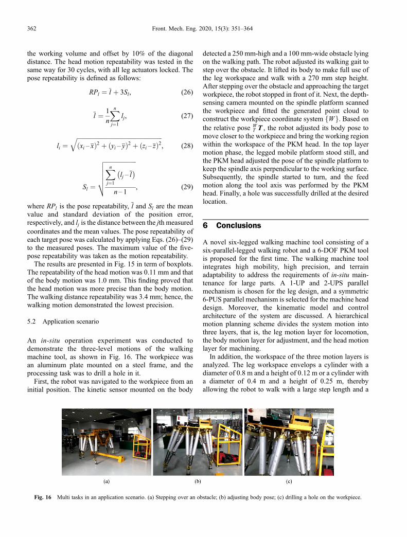
An in-situ operation experiment was conducted todemonstrate the three-level motions of the walkingmachine tool, as shown in Fig. 16. The workpiece wasan aluminum plate mounted on a steel frame, and theprocessing task was to drill a hole in it.First, the robot was navigated to the workpiece from an
initial position. The kinetic sensor mounted on the body
detected a 250 mm-high and a 100 mm-wide obstacle lyingon the walking path. The robot adjusted its walking gait tostep over the obstacle. It lifted its body to make full use ofthe leg workspace and walk with a 270 mm step height.After stepping over the obstacle and approaching the targetworkpiece, the robot stopped in front of it. Next, the depth-sensing camera mounted on the spindle platform scannedthe workpiece and fitted the generated point cloud toconstruct the workpiece coordinate system fWg. Based onthe relative pose W
T T , the robot adjusted its body pose tomove closer to the workpiece and bring the working regionwithin the workspace of the PKM head. In the top layermotion phase, the legged mobile platform stood still, andthe PKM head adjusted the pose of the spindle platform tokeep the spindle axis perpendicular to the working surface.Subsequently, the spindle started to turn, and the feedmotion along the tool axis was performed by the PKMhead. Finally, a hole was successfully drilled at the desiredlocation.
6 Conclusions
A novel six-legged walking machine tool consisting of asix-parallel-legged walking robot and a 6-DOF PKM toolis proposed for the first time. The walking machine toolintegrates high mobility, high precision, and terrainadaptability to address the requirements of in-situ main-tenance for large parts. A 1-UP and 2-UPS parallelmechanism is chosen for the leg design, and a symmetric6-PUS parallel mechanism is selected for the machine headdesign. Moreover, the kinematic model and controlarchitecture of the system are discussed. A hierarchicalmotion planning scheme divides the system motion intothree layers, that is, the leg motion layer for locomotion,the body motion layer for adjustment, and the head motionlayer for machining.In addition, the workspace of the three motion layers is
analyzed. The leg workspace envelops a cylinder with adiameter of 0.8 m and a height of 0.12 m or a cylinder witha diameter of 0.4 m and a height of 0.25 m, therebyallowing the robot to walk with a large step length and a
Fig. 16 Multi tasks in an application scenario. (a) Stepping over an obstacle; (b) adjusting body pose; (c) drilling a hole on the workpiece.
362 Front. Mech. Eng. 2020, 15(3): 351–364

large step height. The workspace of the body and head canenvelop a cube with a side length of 0.25 and 0.075 m,respectively. Motion simulations show how these motionlayers work. In addition, their repeatability is testedthrough experiments. The repeatability of the head motion,body motion, and walking distance is 0.11, 1.0, and 3.4mm, respectively. The results prove the rationality of thetask division for the three motion layers.Finally, a comprehensive experiment that requires the
robot to step over a 250 mm-high obstacle and perform anautonomous drilling task is conducted to demonstrate theworkflow of the system and prove the validity of thehierarchical motion planning scheme. The walkingmachine tool presented in this paper will hopefully becomean intelligent and multifunctional solution for in-situprocessing of large parts.
Acknowledgements This work was funded by the National NaturalScience Foundation of China (Grant No. U1613208), the National KeyResearch and Development Plan of China (Grant No. 2017YFE0112200),and the European Union’s Horizon 2020 Research and InnovationProgramme under the Marie Skłodowska-Curie grant agreement No. 734575.
Electronic Supplementary Material The supplementary material can befound in the online version of this article (https://doi.org/10.1007/s11465-020-0594-2) and is accessible to authorized users.
Open Access This article is licensed under a Creative CommonsAttribution 4.0 International License, which permits use, sharing, adaptation,distribution and reproduction in any medium or format, as long as you giveappropriate credit to the original author(s) and the source, provide a link to theCreative Commons licence, and indicate if changes were made.The images or other third party material in this article are included in the
article’s Creative Commons licence, unless indicated otherwise in a creditline to the material. If material is not included in the article’s CreativeCommons licence and your intended use is not permitted by statutoryregulation or exceeds the permitted use, you will need to obtain permissiondirectly from the copyright holder.To view a copy of this licence, visit http://creativecommons.org/licenses/
by/4.0/.
References
1. Uriarte L, Zatarain M, Axinte D, et al. Machine tools for large parts.
CIRP Annals, 2013, 62(2): 731–750
2. Bostelman R, Hong T, Marvel J. Survey of research for performance
measurement of mobile manipulators. Journal of Research of the
National Institute of Standards and Technology, 2016, 121: 342–
366
3. Suárez R, Palomo-Avellaneda L, Martinez J, et al. Development of a
dexterous dual-arm omnidirectional mobile manipulator. IFAC-
PapersOnLine, 2018, 51(22): 126–131
4. Olazagoitia J L, Wyatt S. New PKM Tricept T9000 and Its
Application to Flexible Manufacturing at Aerospace Industry. SAE
Technical Paper 2007-01-3820, 2007
5. Law M, Rentzsch H, Ihlenfeldt S. Development of a dynamic
substructuring framework to facilitate in situ machining solutions
using mobile machine tools. Procedia Manufacturing, 2015, 1: 756–
767
6. Hazel B, Côté J, Laroche Y, et al. In-situ robotic interventions in
hydraulic turbines. In: Proceedings of the 2010 1st International
Conference on Applied Robotics for the Power Industry. Montreal:
IEEE, 2010, 11637498
7. Hazel B, Boudreault E, Côté J, et al. Robotic post-weld heat
treatment for in situ repair of stainless steel turbine runners. In:
Proceedings of the 2014 3rd International Conference on Applied
Robotics for the Power Industry. Foz do Iguassu: IEEE, 2014,
14903693
8. Collado V, Arana J, Saenz A. A Crawling Portable Robot for
Drilling Operations in Large Air Frame Components. SAE
Technical Paper 2005-01-3337, 2005
9. Marguet B, Cibiel C, De Francisco Ó, et al. Crawler Robots for
Drilling and Fastener Installation: An Innovative Breakthrough in
Aerospace Automation. SAE Technical Paper 2008-01-2292, 2008
10. Pessi P, Wu H, Handroos H, et al. A mobile robot with parallel
kinematics to meet the requirements for assembling and machining
the ITER vacuum vessel. Fusion Engineering and Design, 2007,
82(15–24): 2047–2054
11. Irawan A, Nonami K. Optimal impedance control based on body
inertia for a hydraulically driven hexapod robot walking on uneven
and extremely soft terrain. Journal of Field Robotics, 2011, 28(5):
690–713
12. Santos P G D, Garcia E, Cobano J A, et al. SIL06: A six-legged
robot for humanitarian de-mining tasks. In: Proceedings of World
Automation Congress. Seville: IEEE, 2004, 15: 523–528
13. Kashiri N, Baccelliere L, Muratore L, et al. CENTAURO: A hybrid
locomotion and high power resilient manipulation platform. IEEE
Robotics and Automation Letters, 2019, 4(2): 1595–1602
14. Yang H, Krut S, Pierrot F, et al. On the design of mobile parallel
robots for large workspace applications. In: Proceedings of ASME
2011 International Design Engineering Technical Conferences and
Computers and Information in Engineering Conference. Volume 6:
35th Mechanisms and Robotics Conference, Parts A and B.
Washington, D.C.: ASME, 2011, 767–776
15. Yang H, Krut S, Baradat C, et al. Locomotion approach of
REMORA: A reonfigurable mobile robot for manufacturing
Applications. In: Proceedings of 2011 IEEE/RSJ International
Conference on Intelligent Robots and Systems. San Francisco:
IEEE, 2011: 5067–5072
16. Rushworth A, Axinte D, Raffles M, et al. A concept for actuating
and controlling a leg of a novel walking parallel kinematic machine
tool. Mechatronics, 2016, 40: 63–77
17. Olarra A, Axinte D, Uriarte L, et al. Machining with the
WalkingHex: A walking parallel kinematic machine tool for in
situ operations. CIRP Annals, 2017, 66(1): 361–364
18. Li Y G, Liu H T, Zhao X M, et al. Design of a 3-DOF PKM module
for large structural component machining. Mechanism and Machine
Theory, 2010, 45(6): 941–954
19. Tunc L T, Shaw J. Experimental study on investigation of dynamics
of hexapod robot for mobile machining. International Journal of
Advanced Manufacturing Technology, 2016, 84: 817–830
20. Barnfather J D, Goodfellow M J, Abram T. Positional capability of a
hexapod robot for machining applications. International Journal of
Advanced Manufacturing Technology, 2017, 89(1–4): 1103–1111
21. Huang T, Wang P F, Zhao X M, et al. Design of a 4-DOF hybrid
Jimu LIU et al. A novel six-legged walking machine tool for in-situ operations 363

PKM module for large structural component assembly. CIRP
Annals, 2010, 59(1): 159–162
22. Pan Y, Gao F. Kinematic Performance Analysis for Hexapod
Mobile Robot Using Parallel Mechanism. In: Proceedings of ASME
2014 International Design Engineering Technical Conferences and
Computers and Information in Engineering Conference. Volume
5A: 38th Mechanisms and Robotics Conference. Buffalo: ASME,
2014, V05AT08A089
23. Chen Z J, Gao F, Pan Y. Novel door-opening method for six-legged
robots based on only force sensing. Chinese Journal of Mechanical
Engineering, 2017, 30(5): 1227–1238
24. Zhao Y, Gao F, Hu Y. Novel method for six-legged robots turning
valves based on force sensing. Mechanism and Machine Theory,
2019, 133: 64–83
25. Rao A B K, Rao P V M, Saha S K. Workspace and dexterity
analyses of hexaslide machine tools. In: Proceedings of International
Conference on Robotics and Automation. Taipei: IEEE, 2003, 3:
4104–4109
26. BS EN ISO 9283:1998 Manipulating Industrial Robots—Perfor-
mance Criteria and Related Test Methods. 1998
364 Front. Mech. Eng. 2020, 15(3): 351–364