LISTED DIRECT VENT MILLIVOLT GAS-FIRED WALL FURNACE · listed direct vent millivolt gas-fired wall...
23
WS-415-090 / 04.03.00 W ARNING: ARNING: ARNING: ARNING: ARNING: If the information in these instructions is not followed exactly, a fire or explosion may result causing property damage, personal injury or death. FOR YOUR SAFETY FOR YOUR SAFETY FOR YOUR SAFETY FOR YOUR SAFETY FOR YOUR SAFETY Do not store or use gasoline or other flammable vapours and liquids in the vicinity of this or any other appliance. WHA WHA WHA WHA WHA T T T T T T O DO IF YOU SMELL O DO IF YOU SMELL O DO IF YOU SMELL O DO IF YOU SMELL O DO IF YOU SMELL GAS: GAS: GAS: GAS: GAS: • Do not try to light any appliance. • Do not touch any electrical switch. • Do not use any phone in your building. Installation and service must be performed by a qualified installer, service agency or the gas supplier. • Immediately call your gas supplier from a neighbour's phone. Follow the gas supplier's instructions. • If you cannot reach your gas supplier, call the fire department. LISTED DIRECT VENT MILLIVOL LISTED DIRECT VENT MILLIVOL LISTED DIRECT VENT MILLIVOL LISTED DIRECT VENT MILLIVOL LISTED DIRECT VENT MILLIVOLT GAS-FIRED WALL FURNACE GAS-FIRED WALL FURNACE GAS-FIRED WALL FURNACE GAS-FIRED WALL FURNACE GAS-FIRED WALL FURNACE INST INST INST INST INSTALLA ALLA ALLA ALLA ALLATION AND OPERA TION AND OPERA TION AND OPERA TION AND OPERA TION AND OPERATION INSTRUCTIONS FOR: TION INSTRUCTIONS FOR: TION INSTRUCTIONS FOR: TION INSTRUCTIONS FOR: TION INSTRUCTIONS FOR: NATURAL GAS MODEL GD27 - N GD27 - N GD27 - N GD27 - N GD27 - N PROPANE GAS MODEL GD27 - P GD27 - P GD27 - P GD27 - P GD27 - P CERTIFIED FOR CANADA AND UNITED STATES USING ANSI / AGA / CGA METHODS INSTALLER: THESE INSTRUCTIONS MUST BE CONVEYED TO AND REMAIN WITH THE HOMEOWNER. CERTIFIED UNDER CANADIAN AND AMERICAN NATIONAL STANDARDS, CSA 2.33, AND ANSI Z21.88 RESPECTIVELY FOR VENTED GAS FIREPLACE HEATERS Fax: (705)722-6031 Email: [email protected] Web: www.napoleon.on.ca Wolf Steel Ltd., RR#1, 9 Napoleon Rd., Barrie, On., Canada L4M 4Y8 (705)721-1212 R-2000
Transcript of LISTED DIRECT VENT MILLIVOLT GAS-FIRED WALL FURNACE · listed direct vent millivolt gas-fired wall...

1
WS-415-090 / 04.03.00
WWWWWARNING:ARNING:ARNING:ARNING:ARNING: If the information in these instructions is not followed exactly, a fire orexplosion may result causing property damage, personal injury or death.
FOR YOUR SAFETYFOR YOUR SAFETYFOR YOUR SAFETYFOR YOUR SAFETYFOR YOUR SAFETYDo not store or use gasoline or other flammable vapours and liquids in the vicinity of
this or any other appliance.
WHAWHAWHAWHAWHATTTTT T T T T TO DO IF YOU SMELLO DO IF YOU SMELLO DO IF YOU SMELLO DO IF YOU SMELLO DO IF YOU SMELL GAS: GAS: GAS: GAS: GAS:
• Do not try to light any appliance.• Do not touch any electrical switch.• Do not use any phone in your building.
Installation and service must be performed by a qualified installer, serviceagency or the gas supplier.
• Immediately call your gas supplier froma neighbour's phone. Follow the gassupplier's instructions.• If you cannot reach your gas supplier,call the fire department.
LISTED DIRECT VENT MILLIVOLLISTED DIRECT VENT MILLIVOLLISTED DIRECT VENT MILLIVOLLISTED DIRECT VENT MILLIVOLLISTED DIRECT VENT MILLIVOLTTTTTGAS-FIRED WALL FURNACEGAS-FIRED WALL FURNACEGAS-FIRED WALL FURNACEGAS-FIRED WALL FURNACEGAS-FIRED WALL FURNACE
INSTINSTINSTINSTINSTALLAALLAALLAALLAALLATION AND OPERATION AND OPERATION AND OPERATION AND OPERATION AND OPERATION INSTRUCTIONS FOR:TION INSTRUCTIONS FOR:TION INSTRUCTIONS FOR:TION INSTRUCTIONS FOR:TION INSTRUCTIONS FOR:
NATURAL GAS MODEL GD27 - NGD27 - NGD27 - NGD27 - NGD27 - NPROPANE GAS MODEL GD27 - PGD27 - PGD27 - PGD27 - PGD27 - P
CERTIFIED FOR CANADA AND UNITED STATES USING ANSI / AGA / CGA METHODS
INSTALLER: THESE INSTRUCTIONS MUST BE CONVEYED TO AND REMAIN WITH THE HOMEOWNER.CERTIFIED UNDER CANADIAN AND AMERICAN NATIONAL STANDARDS, CSA 2.33, AND ANSI Z21.88 RESPECTIVELY FOR VENTED GAS FIREPLACE HEATERS
Fax: (705)722-6031 Email: [email protected]: www.napoleon.on.ca
Wolf Steel Ltd., RR#1, 9 Napoleon Rd.,Barrie, On., Canada L4M 4Y8 (705)721-1212
R-2000

2
WS-415-090 / 04.03.00
TABLE of CONTENTSPG 15 OPTIONAL BLOWER INSTALLATION
16 OPTIONAL FAN &THERMOSTATICSENSOR
17 OPERATION / MAINTENANCEOperating InstructionsMaintenance
18 ADJUSTMENTSPilot Burner AdjustmentVenturi AdjustmentRestricting Vertical Vents
19-20 REPLACEMENTSOrdering Replacement PartsReplacement PartsVent KitsTerminal KitsAccessories
21-22 TROUBLE SHOOTING GUIDE
PG 2-4 INTRODUCTIONWarrantyGeneral InstructionsGeneral InformationCare of Glass & Plated Parts
5-7 VENTINGVenting LengthsAir Terminal LocationsSpecial Installation Example
8-12 INSTALLATIONWall & Ceiling ProtectionUsing Flexible Vent ComponentsFireplace Vent ConnectionUsing Rigid Vent ComponentsGas InstallationMobile Home InstallationFraming
13-14 FINISHINGLog PlacementOptional Glowing EmbersDoor, Louvre & Trim Removal & Installation
PLEASE RETAIN THIS MANUAL FOR FUTURE REFERENCE
WARNING••••• Do not burn wood or other materials in this fireplace.• Adults and especially children should be alerted to the hazards of high surface temperatures
and should stay away to avoid burns or clothing ignition. Supervise young children when theyare in the same room as the fireplace.
• Due to high temperatures, the fireplace should be located out of traffic and away from furnitureand draperies.
• Clothing or other flammable material should not be placed on or near the fireplace.• Any safety screen or guard removed for servicing must be replaced prior to operating the fire-
place.• It is imperative that the control compartments, burners and circulating blower and its passage-
way in the fireplace and venting system are kept clean. The fireplace and its venting systemshould be inspected before use and at least annually by a qualified service person. More fre-quent cleaning may be required due to excessive lint from carpeting, bedding material, etc. Thefireplace area must be kept clear and free from combustible materials, gasoline and other flam-mable vapours and liquids.
• Under no circumstances should this fireplace be modified.• This fireplace must not be connected to a chimney flue pipe serving a separate solid fuel burning
appliance.• Do not use this fireplace if any part has been under water. Immediately call a qualified service
technician to inspect the fireplace and to replace any part of the control system and any gascontrol which has been under water.
• Do not operate the fireplace with the glass door removed, cracked or broken. Replacement ofthe glass should be done by a licensed or qualified service person. Use only with a glass doorcertified with the fireplace.
• Do not strike or slam shut the fireplace glass door.

3
WS-415-090 / 04.03.00
NAPOLEON gas fireplaces are manufactured under the strict Standard of the world recognizedISO9002 Quality Assurance Certificate.
NAPOLEON products are designed with superior components and materials, assembled by trained craftsmenwho take great pride in their work. The burner and valve assembly are leak and test-fired at a quality teststation. The complete fireplace is thoroughly inspected by a qualified technician before packaging to ensure thatyou, the customer, receives the quality product that you expect from NAPOLEON.
NAPOLEON GAS FIREPLACE PRESIDENT'S LIFETIME LIMITED WARRANTY
The following materials and workmanship in your new The following materials and workmanship in your new The following materials and workmanship in your new The following materials and workmanship in your new The following materials and workmanship in your new NAPOLEONNAPOLEONNAPOLEONNAPOLEONNAPOLEON gas fireplace are gas fireplace are gas fireplace are gas fireplace are gas fireplace arewarranted against defects for as long as you own the fireplace. This covers: combustionwarranted against defects for as long as you own the fireplace. This covers: combustionwarranted against defects for as long as you own the fireplace. This covers: combustionwarranted against defects for as long as you own the fireplace. This covers: combustionwarranted against defects for as long as you own the fireplace. This covers: combustionchamber, heat exchanger, stainless steel burner, phazer™ logs and embers, ceramic glasschamber, heat exchanger, stainless steel burner, phazer™ logs and embers, ceramic glasschamber, heat exchanger, stainless steel burner, phazer™ logs and embers, ceramic glasschamber, heat exchanger, stainless steel burner, phazer™ logs and embers, ceramic glasschamber, heat exchanger, stainless steel burner, phazer™ logs and embers, ceramic glass(thermal breakage only), gold plated parts against tarnishing, porcelainized enamelled com-(thermal breakage only), gold plated parts against tarnishing, porcelainized enamelled com-(thermal breakage only), gold plated parts against tarnishing, porcelainized enamelled com-(thermal breakage only), gold plated parts against tarnishing, porcelainized enamelled com-(thermal breakage only), gold plated parts against tarnishing, porcelainized enamelled com-ponents and aluminum extrusion trims.ponents and aluminum extrusion trims.ponents and aluminum extrusion trims.ponents and aluminum extrusion trims.ponents and aluminum extrusion trims.
Electrical (110V and millivolt) components and wearable parts such as blowers, gas valves,Electrical (110V and millivolt) components and wearable parts such as blowers, gas valves,Electrical (110V and millivolt) components and wearable parts such as blowers, gas valves,Electrical (110V and millivolt) components and wearable parts such as blowers, gas valves,Electrical (110V and millivolt) components and wearable parts such as blowers, gas valves,thermal switch, switches, wiring, remote controls, ignitor, gasketing, and pilot assembly arethermal switch, switches, wiring, remote controls, ignitor, gasketing, and pilot assembly arethermal switch, switches, wiring, remote controls, ignitor, gasketing, and pilot assembly arethermal switch, switches, wiring, remote controls, ignitor, gasketing, and pilot assembly arethermal switch, switches, wiring, remote controls, ignitor, gasketing, and pilot assembly arecovered and covered and covered and covered and covered and NAPOLEONNAPOLEONNAPOLEONNAPOLEONNAPOLEON will provide replacement parts free of charge during the first yearwill provide replacement parts free of charge during the first yearwill provide replacement parts free of charge during the first yearwill provide replacement parts free of charge during the first yearwill provide replacement parts free of charge during the first yearof the limited warranty.of the limited warranty.of the limited warranty.of the limited warranty.of the limited warranty.
Labour related to warranty repair is covered free of charge during the first year. RepairLabour related to warranty repair is covered free of charge during the first year. RepairLabour related to warranty repair is covered free of charge during the first year. RepairLabour related to warranty repair is covered free of charge during the first year. RepairLabour related to warranty repair is covered free of charge during the first year. Repairwork, however, requires the prior approval of an authorized company official. Labour costswork, however, requires the prior approval of an authorized company official. Labour costswork, however, requires the prior approval of an authorized company official. Labour costswork, however, requires the prior approval of an authorized company official. Labour costswork, however, requires the prior approval of an authorized company official. Labour coststo the account of to the account of to the account of to the account of to the account of NAPOLEONNAPOLEONNAPOLEONNAPOLEONNAPOLEON are based on a predetermined rate schedule and any repair are based on a predetermined rate schedule and any repair are based on a predetermined rate schedule and any repair are based on a predetermined rate schedule and any repair are based on a predetermined rate schedule and any repairwork must be done through an authorized work must be done through an authorized work must be done through an authorized work must be done through an authorized work must be done through an authorized NAPOLEONNAPOLEONNAPOLEONNAPOLEONNAPOLEON dealer. dealer. dealer. dealer. dealer.
CONDITIONS AND LIMITATIONS
NAPOLEON warrants its products against manufacturing defects to the original purchaser only -- i.e., the individual or legal entity (registered customer) whose name appears on thewarranty registration card filed with NAPOLEON -- provided that the purchase was made through an authorized NAPOLEON dealer and is subject to the following conditions and limitations:
This factory warranty is nontransferable and may not be extended whatsoever by any of our representatives.
The gas fireplace must be installed by a licenced, authorized service technician or contractor. Installation must be done in accordance with the installation instructions included with theproduct and all local and national building and fire codes.
This limited warranty does not cover damages caused by misuse, lack of maintenance, accident, alterations, abuse or neglect and parts installed from other manufacturers will nullifythis warranty.
This limited warranty further does not cover any scratches, dents, corrosion or discolouring caused by excessive heat, abrasive and chemical cleaners nor chipping on porcelain enamelparts, mechanical breakage of PHAZER™ logs and embers, nor any venting components used in the installation of the fireplace.
NAPOLEON warrants its stainless steel burners against defects in workmanship and material for life, subject to the following conditions: During the first 10 years NAPOLEON will replaceor repair the defective parts at our option free of charge. From 10 years to life, NAPOLEON will provide replacement burners at 50% of the current retail price.
In the first year only, this warranty extends to the repair or replacement of warranted parts which are defective in material or workmanship provided that the product has been operatedin accordance with the operation instructions and under normal conditions.
After the first year, with respect to this President's Limited Lifetime Warranty, NAPOLEON may, at its discretion, fully discharge all obligations with respect to this warranty by refundingto the original warranted purchaser the wholesale price of any warranted but defective part(s).
After the first year, NAPOLEON will not be responsible for installation, labour or any other costs or expenses related to the reinstallation of a warranted part, and such expenses are notcovered by this warranty.
Notwithstanding any provisions contained in this President's Limited Lifetime Warranty, NAPOLEON’S responsibility under this warranty is defined as above and it shall not in any eventextend to any incidental, consequential or indirect damages.
This warranty defines the obligations and liability of NAPOLEON with respect to the NAPOLEON gas fireplace and any other warranties expressed or implied with respect to this product,its components or accessories are excluded.
NAPOLEON neither assumes, nor authorizes any third party to assume, on its behalf, any other liabilities with respect to the sale of this product. NAPOLEON will not be responsiblefor: over-firing, downdrafts, spillage caused by environmental conditions such as rooftops, buildings, nearby trees, hills, mountains, inadequate vents or ventilation, excessive ventingconfigurations, insufficient makeup air, or negative air pressures which may or may not be caused by mechanical systems such as exhaust fans, furnaces, clothes dryers, etc.
Any damages to fireplace, combustion chamber, heat exchanger, brass trim or other component due to water, weather damage, long periods of dampness, condensation, damagingchemicals or cleaners will not be the responsibility of NAPOLEON.
The bill of sale or copy will be required together with a serial number and a model number when making any warranty claims from your authorized dealer. The warranty registrationcard must be returned within fourteen days to register the warranty.
NAPOLEON reserves the right to have its representative inspect any product or part thereof prior to honouring any warranty claim.
ALL SPECIFICATIONS AND DESIGNS ARE SUBJECT TO CHANGE WITHOUT PRIOR NOTICE DUE TO ON-GOING PRODUCT IMPROVEMENTS. NAPOLEON® IS A REGISTEREDTRADEMARK OF WOLF STEEL LTD. PATENTS U.S. 5.303.693.801 - CAN. 2.073.411, 2.082.915. © WOLF STEEL LTD.

4
WS-415-090 / 04.03.00
CARE OF GLASS, AND PLATED PARTSDo not use abrasive cleaners to clean plated parts. Bufflightly with a clean dry cloth. The glass is 3/16" ceramicglass available from your Napoleon / Wolf Steel Ltd. dealer.DO NOT SUBSTITUTE MATERIALS. Clean the glass afterthe first 10 hours of operation with a recommended gasfireplace glass cleaner. Thereafter clean as required. DONOT CLEAN GLASS WHEN HOT! If the glass is not keptclean permanent discolouration and / or blemishes mayresult.
No external electricity (110 volts or 24 volts) isrequired for the gas system operation.Purge all gas lines with the glass door of the fire-place removed. Assure that a continuous gas flowis at the burner before installing the door.Under extreme vent configurations, allow severalminutes (5-15) for the flame to stabilize after igni-tion.Six inches is the minimum bend radius allowed forthe 7" diameter flexible liner.Provide adequate ventilation air. Provide adequateaccessibility clearance for servicing and operat-ing the fireplace. Never obstruct the front openingof the fireplace.Objects placed in front of the fireplace must bekept a minimum of 48" from the front face of theunit.Expansion / contraction nosies during heating upand cooling down cycles are normal and are to beexpected.
GENERAL INSTRUCTIONSTHIS GAS FIREPLACE SHOULD BE INSTALLED ANDSERVICED BY A QUALIFIED INSTALLER to conform withlocal codes. In absence of local codes, install to the cur-rent CAN/CGA -B149 Installation Code in Canada or to theNational Fuel Gas Code, ANSI Z223.1-1988, and NFPA54-1988 in the United States. Mobile home installationmust conform with local codes or in the absence of localcodes, install to the current standard for gas equippedmobile housing CAN/CSA ZA240 MH Series in Canada orANSI Z223.1-1988 and NFPA 54-1988 in the United States.
The fireplace and its individual shutoff valve must be dis-connected from the gas supply piping system during anypressure testing of that system at test pressures in ex-cess of 1/2 psig (3.5 kPa). The fireplace must be isolatedfrom the gas supply piping system by closing its individualmanual shutoff valve during any pressure testing of thegas supply piping system at test pressures equal to orless than 1/2 psig (3.5 kPa).
If the optional fan or blower is installed, the junction boxmust be electrically connected and grounded in accordancewith local codes. In the absence of local codes, use thecurrent CSA C22.1 CANADIAN ELECTRICAL CODE inCanada or the ANSI/NFPA 70-1996 NATIONAL ELECTRI-CAL CODE in the United States.
GENERAL INFORMATIONFOR YOUR SATISFACTION, THIS FIREPLACE HAS BEENTEST-FIRED TO ASSURE ITS OPERATION AND QUAL-ITY! Maximum input is 27,000 BTU/hr for natural gas andpropane. When the fireplace is installed at elevations above4,500ft, and in the absense of specific recommendationsfrom the local authority having jurisdiction, the certified highaltitude input rating shall be reduced at the rate of 4% foreach additional 1,000ft. Maximum output for natural gas is23,220 BTU/hr at an efficiency of 86% with the fan on, and23,814 BTU/hr for propane at an efficiency of 88% with thefan on. Minimum A.F.U.E. (annual fuel utilization efficiency)rating is 64% for natural gas and 65% for propane.
Minimum inlet gas supply pressure is 4.5 inches watercolumn for natural gas and 11 inches water column forpropane. Maximum inlet gas pressure is 7 inches watercolumn for natural gas and 13 inches water column forpropane. Manifold pressure under flow conditions is 3.5inches water column for natural gas and 10 inches watercolumn for propane.
This fireplace is approved for bathroom, bedroom and bed-sitting room installations and is suitable for mobile homeinstallation. The natural gas model can only be installed ina mobile home that is permanently positioned on its siteand fueled with natural gas.
FIGURE 1

5
WS-415-090 / 04.03.00
VENTING LENGTHS AND AIR TERMI-NAL LOCATIONSUse only Napoleon or Simpson Dura-Vent Model DV-GSventing components. Minimum and maximum vent lengths,for both horizontal and vertical installations, and air termi-nal locations for either system are set out in this manualand must be adhered to. For Simpson Dura-Vent, followthe installation procedure provided with the venting com-ponents.
When using Napoleon venting components, use only thefollowing vent kits: WALL TERMINAL KIT GD222, or 1/12TO 7/12 PITCH ROOF TERMINAL KIT GD110, 8/12 TO 12/12 ROOF TERMINAL KIT GD111, FLAT ROOF TERMINALKIT GD112 or PERISCOPE KIT GD201 (for wall penetrationbelow grade) in conjunction with the various terminations,use either the 5 foot vent kit GD220 or the 10 foot vent kitGD330.
These vent kits allow for eitherhorizontal or vertical venting ofthe fireplace. FIGURES 2, 3, 5 &6. The maximum number of 4"flexible connections is two hori-zontally or three vertically (ex-cluding the fireplace and the airterminal connections).
For optimum flame appearanceand fireplace performance,keep the vent length and num-ber of elbows to a minimum.The air terminal must remainunobstructed at all times. Exam-ine the air terminal at least oncea year to verify that it is unob-structed and undamaged.
When terminating vertically, the vertical rise is a minimum3 feet and a maximum 40 feet above the fireplace.
For safe and proper operation of the fireplace follow theventing instruction exactly.Deviation from the minimum vertical vent length can cre-ate difficulty in burner start-up and/or carboning.If vertical rises greater than 57 inches are necessary, theincreased rise must be deducted from the horizontal run.Provide a means for visually checking the vent connec-tion to the fireplace after the fireplace is installed.Use a firestop when penetrating interior walls, floor orceiling.Vent lengths that pass through unheated spaces (at-tics, garages, crawl spaces) should be insulated withthe insulation wrapped in a protective sleeve to mini-mize condensation.The fireplace must be installed against finished walls.Do not install against a vapour barrier or exposed insu-lation.
Horizontal runs may have a 0 inch rise per foot in all casesusing Simpson Dura-Vent or Napoleon flexible or rigid vent-ing components when venting as illustrated in Figures 3a-c.
FIGURE 2
When venting, the horizontal run must be kept to a mini-mum of 11 inches or a maximum of 20 feet. If a 20 foothorizontal run is required, the fireplace must have a mini-mum vertical rise immediately off the fireplace of 57inches. FIGURES 3a-c.
VENTING
Minimum clearance to combustible constructionfrom fireplace to vent surfaces:sides, back, bottom and top 0 inchesvent pipe 1 inchrecessed depth 13-3/4 inches
FIGURES 3a - d

6
WS-415-090 / 04.03.00
A terminal shall not terminate directly above a sidewalkor paved driveway which is located betweeen two singlefamily dwellings and serves both dwellings. Localcodes or regulations may require different clearances.
Do not allow the inside liner to bunch up on horizontal orvertical runs and elbows. Keep it pulled tight. A 1¼" airgap all around between the inner liner and outer liner isrequired for safe operation. Use a firestop when pen-etrating interior walls, floor or ceiling.
CALCULATED HORIZONTAL VENT RUN IN FEET
REQUIRED VERTI-CAL RISE FROMFIREPLACE TOFIRST ELBOW ININCHES
FIGURE 4
B
C
A
FIGURE 5
Use the chart on this page to calculate horizontal runs forvertical rises between 10 and 57 inches. FIGURE 4.
When calculating maximum run lengths, include 5 feet foreach 90° or 45° elbow.
(DO NOT INCLUDE THE FIRST ELBOW DIRECTLY OFFTHE UNIT.)
SPECIAL INSTALLATION EXAMPLEWhen a horizontal offset isrequired in a through-the-roof installation, the follow-ing procedure for ventlength calculations must befollowed:
In an installation as shownin FIGURE 5, lengths A andC are known based onroom height and roof re-quirements. Any 90° and45° elbows must be calcu-lated as 5 feet of ventingeach except for the one im-except for the one im-except for the one im-except for the one im-except for the one im-mediately at the fireplacemediately at the fireplacemediately at the fireplacemediately at the fireplacemediately at the fireplacewhich is excludedwhich is excludedwhich is excludedwhich is excludedwhich is excluded.
The allowable horizontal run can be calculated using theseparameters. In this example, the total vertical height is 20feet (length "A" is required to be 11 feet while length "C"needs to be 9 feet). The maximum vertical length is 40 feetand all runs and elbows must be subtracted from this maxi-mum vertical length.
The maximum allowable horizontal run that "B" can be is:
40 ft. (maximum vertical run length)
-11 ft. (through the roof vertical rise "A")
-10 ft. (2 - 90° elbow)
- 9 ft. (vertical run "C")
10 ft. (maximum allowable horizontal length for "B")
The length of "B" must never be greater than the lengthof "A" and "C" combined.

7
WS-415-090 / 04.03.00
FIGURE 6
AIR AIR AIR AIR AIR TERMINTERMINTERMINTERMINTERMINAL INSTAL INSTAL INSTAL INSTAL INSTALLAALLAALLAALLAALLATIONS:TIONS:TIONS:TIONS:TIONS:
***** Recommended to prevent condensation on windows and thermal breakage********** It is recommended to use a heat shield and to maximize the distance to vinyl clad soffits.*************** The periscope GD-201 requires a minimum 18 inches clearance from an inside corner.******************** This is a recommended distance. For additional requirements check local codes.††††† Three feet above if within 10 feet horizontally.‡‡‡‡‡ A vent shall not terminate directly above a sidewalk or paved driveway that is located between two single family
dwellings and serves both dwellings.†††††††††† Permitted only if the veranda, porch, deck or balcony is fully open on a minimum of two sides beneath the floor.†*†*†*†*†* Recommenced to prevent recirculation of exhaust products. For additional requirements check local codes.
A
B
C
D
E
F
G
H
I
J
K
L
M
N
O
12 INCHES
9 INCHES
12 INCHES*
18 INCHES**
12 INCHES**
0 INCHES
0 INCHES***
2 INCHES***
3 FEET****
3 FEET****
9 INCHES
3 FEET†
7 FEET****
12 INCHES****
16 INCHES
2 FEET†*
Clearance above grade, veranda porch, deck or balcony.
Clearance to windows or doors that open.
Clearance to permanently closed windows.
Vertical clearance to ventilated soffit located above the terminal withina horizontal distance of 2 feet from the centerline of the terminal.
Clearance to unventilated soffit.
Clearance to an outside corner wall.
Clearance to an inside non-combustible corner wall or protrudingnon-combustible obstructions (chimney, etc.).
Clearance to an inside combustible corner wall or protruding com-bustible obstructions ( vent chase, etc.).
Clearance to each side of the centerline extended above the meter/ regulator assembly.
Clearance to a service regulator vent outlet.
Clearance to a non-mechanical air supply inlet to the building or acombustion air inlet to any other appliance.
Clearance to a mechanical air supply inlet.
Clearance above a paved sidewalk or paved driveway located onpublic property unless fitted with a heat shield kit GD-301.
Clearance under a veranda, porch, deck or balcony.
Clearance above the roof.
Clearance from an adjacent wall including neighbouring buildings.
CANADIAN U.S.A.
12 INCHES
12 INCHES
12 INCHES*
18 INCHES**
12 INCHES**
0 INCHES
0 INCHES***
2 INCHES***
3 FEET
6 FEET
12 INCHES
6 FEET
7 FEET‡
12 INCHES††
16 INCHES
2 FEET†*
INSTALLATIONS

8
WS-415-090 / 04.03.00
VERTICAL INSTALLA-TION: This applicationoccurs when ventingthrough a roof.FIGURE 2. Installationkits for various roofpitches are availablefrom your Napoleondealer. See Accesso-ries to order the specifickit required.
1. Determine the air terminal location, cut and frame 9½inch openings in the ceiling and the roof to provide theminimum 1 inch clearance between the fireplace pipe /liner and any combustible material. Try to center the ex-haust pipe location midway between two joist to preventhaving to cut them. Use a plumb bob to line up the center ofthe openings.
Do not fill this space with any type of material.A vent pipe shield willprevent any materialssuch as insulation,from filling up the 1" airspace around thepipe. FIGURE 11 Nailheaders between thejoist for extra support.
2. Apply a bead of caulking (not supplied) to the frame-work or to the Wolf Steel vent pipe shield plate or equiva-lent (in the case of a finished ceiling), and secure over theopening in the ceiling. FIGURE 10. A firestop must be placedon the bottom of each framed opening in a roof or ceilingthat the venting system passes through. FIGURE 9. Apply abead of caulking all around and place a firestop spacerover the vent shield to restrict cold air from being drawninto the room or around the fireplace. Ensure that bothspacer and shield maintain the required clearance to com-bustibles. Once the vent pipe / liner is installed in its finalposition, apply sealant between the pipe / liner and thefirestop spacer.
3. In the attic, after the pipe / liner has been installed,slide the vent pipe collar down to cover up the open end ofthe shield and tighten. This will prevent any materials, suchas insulation, from filling up the 1" air space around thepipe.
For optimum performance, it is recommended thatFor optimum performance, it is recommended thatFor optimum performance, it is recommended thatFor optimum performance, it is recommended thatFor optimum performance, it is recommended thatall horizontal runs have a minimum ¼ inch riseall horizontal runs have a minimum ¼ inch riseall horizontal runs have a minimum ¼ inch riseall horizontal runs have a minimum ¼ inch riseall horizontal runs have a minimum ¼ inch riseper foot.per foot.per foot.per foot.per foot.FFFFFor safe and proper operation of the fireplace, fol-or safe and proper operation of the fireplace, fol-or safe and proper operation of the fireplace, fol-or safe and proper operation of the fireplace, fol-or safe and proper operation of the fireplace, fol-low the vlow the vlow the vlow the vlow the venting instrenting instrenting instrenting instrenting instructions euctions euctions euctions euctions exactlyxactlyxactlyxactlyxactly.....HORIZONTAL INSTALLA-TION: This application oc-curs when venting through anexterior wall. FIGURES 3a-c.Having determined the air ter-minal location, cut and framea hole in an exterior wall witha minimum square or roundopening of 9½". (As an alter-native to framing, a vent pipeshield may be installed, en-suring a 1" clearance to com-bustibles. See Figure 8.)
1. Mark and cut the vent pipe shield to the determineddepth of the combustible wall. Apply a bead of caulking(not supplied) to the framework or to the shield plate (inthe case of a finished wall) and secure the shield throughthe opening to the interior wall. The final location of thevent pipe shield should maintain the required clearance tothe 7" vent pipe / liner. Do not fill this cavity with any type ofmaterial. Apply a bead of caulking all around and place afirestop spacer over the vent shield to restrict cold air frombeing drawn into the room or around the fireplace. Ensurethat both spacer and shield maintain the required clear-ance to combustibles. Once the vent pipe / liner is installedin its final position, apply sealant between the pipe / linerand the firestop spacer.
FIGURE 8
OR
FIGURE 9
FIGURE 10
FIGURE 11
VENT PIPESHIELD
VENTPIPE
COLLAR
FIGURE 7
INSTALLATIONWALL AND CEILING PROTECTION

9
WS-415-090 / 04.03.00
VERTICAL VENTING INSTALLATION1. Fasten the roof support to the roof using the screws
provided. The roof support is optional. The venting is to beadequately supported using either an alternate methodsuitable to the authority having jurisdiction or the optionalroof support.
2. Stretch the 4" diameter aluminum flexible liner to therequired length. Slip the liner a minimum of 2" over theinner sleeve of the air terminal and secure with 3 #8screws. Seal using a heavy bead of the high temperaturesealant.
3. Repeat using 7" diameter aluminum flexible liner.
4. Thread the air terminalpipe assembly down throughthe roof. The air terminal mustbe located vertically andplumb. Attach the air terminalassembly to the roof support,ensuring that a minimum 16"of air terminal will penetratethe roof when fastened.
DO NOT CLAMP THE FLEXIBLE ALUMINUM LINER.
FIGURE 13
FIGURE 12
For optimum performance, it is recommendedthat all horizontal runs have a minimum ¼ inch
rise per foot.For safe and proper operation of the fireplace,
follow the venting instructions exactly.
HORIZONTAL AIR TERMINAL INSTAL-LATION
INSTALLATIONUSING FLEXIBLE VENT COMPONENTS
1. Stretch the 4" diameter aluminum flexible liner to therequired length taking into account the additional lengthneeded for the finished wall surface. Apply a heavy bead ofthe high temperature sealant, supplied with the unit, to theinside of the 4" liner approximately 1" from the end. Slip theliner a minimum of 2" over the fireplace vent collar andsecure with 3 #8 screws.
2. Using the 7" diameter flexible aluminum liner, applysealant, slide a minimum of 2" over the fireplace combus-tion air collar and secure with 3 #8 screws.
3. Insert the liners through the firestop. Position andsecure the fireplace using the nailing tabs (2 per side)and/or secure to the floor using screws inserted throughthe two ¼" diameter holes in the front left and right cornersof the base. The liners should be flush with the exteriorwall.
The air teminal plate may be recessed into the exte-rior wall or siding by 1½", the depth of the return flange.
4. From outside, apply a bead of the high temperaturesealant to the inside of both liners, approximately 1" fromthe end of each liner.
5. Holding the air terminal (lettering in an upright, read-able position), insert into both liners with a twisting motionto ensure that both the terminal sleeves engage into theliners / sealant. Secure the terminal to the exterior wall andmake weather tight by sealing with caulking (not supplied).
EXTENDED HORIZONTAL AIR TERMI-NAL INSTALLATIONIf more than one length of liner needs to be used to reachthe fireplace, couple them together as illustrated below.Seal the joints using the same procedure as before. Thevent system must be supported approximately every 3 feetfor both vertical and horizontal runs. Use Napoleon sup-port ring assemblies, GA-GD-010.370 or equivalent non-combustible strapping to maintain the minimum clearanceto combustibles as well as to prevent sagging.
Spacers are attached to the 4" inner flex liner at prede-termined intervals to maintain a 1-1/4" air gap to the 7"outer liner. These spacers must not be removed.
FIGURE 14

10
WS-415-090 / 04.03.00
Spacers are attached to the 4" inner flex liner at prede-termined intervals to maintain a 1-1/4" air gap to the 7"outer liner. These spacers must not be removed.
7. If more liner needs to be used to reach the fireplace,follow the same procedure as found in EXTENDED HORI-ZONTAL AIR TERMINAL INSTALLATION. The vent systemmust be supported approximately every 3 feet for both ver-tical and horizontal runs. Use Napoleon support ring as-sembly GA-GD-010.370 or equivalent noncombustiblestrapping to maintain the minimum clearance to combus-tibles as well as to prevent sagging.
FIREPLACE VENT CONNECTION1. Install the 4
inch diameter alu-minum flexibleliner to the fire-place. Secure with3 screws and flatwashers. Seal thejoint and screwholes using thehigh temperaturesealant provided.
2. Install the 7 inch diameter aluminum flexible liner tothe fireplace. Attach and seal the joints.
3. Move the fireplace into position. The two holes in thefireplace base located behind the lower louvre assemblymay be used to attach the fireplace to the floor usingscrews.
5. Remove nailsfrom the shingles,above and to the sidesof the chimney. Placethe flashing over the airterminal and slide itunderneath the sidesand upper edge of theshingles.
Ensure that the air terminal is properly centered within theflashing, giving a 3/4" margin all around. Fasten to the roof.Do not nail through the lower portion of the flashing. Makeweather-tight by sealing with caulking. Where possible,cover the sides and top edges of the flashing with roofingmaterial.
6. Apply a heavybead of weatherproofcaulking 2 inchesabove the f lashing.Slide the storm collararound the air terminaland down to the caulk-ing. Tighten to ensurethat a weather-t ightseal between the airterminal and the collar is achieved. Attach the other stormcollar centered between the air intake and the air exhaustslots onto the air terminal. Tighten securely. Attach the ver-tical rain cap.
FIGURE 15
FIGURE 16
FIGURE 17
For safe and proper operation of the fireplace,follow the venting instructions exactly.For optimum performance, it is recommendedthat all horizontal runs have a minimum ¼ inchrise per foot.
The vent system must be supported approximately every 3feet for both vertical and horizontal runs. Use Napoleonvent spacers WS-615-33 or equivalent every 3 feet and ei-ther side of each elbow to maintain the minimum 1¼" clear-ance between the outer and inner vent pipes. Use Napo-leon support ring assembly GA-GD-010.370 or equivalentnoncombustible strapping to maintain the minimum clear-ance to combustibles for both vertical and horizontal runs.
INSTALLATIONUSING RIGID VENT COMPONENTS
HORIZONTAL AIR TERMINAL INSTAL-LATION
1. Move the fireplace into position. Measure the vent lengthrequired between terminal and fireplace taking into accountthe additional length needed for the finished wall surfaceand any 1¼" overlaps between venting components.
2. Apply high temperature sealant to the outer edge of the4" inner collar of the fireplace. Attach the first vent compo-nent and secure using 3 self tapping screws. Repeat us-ing 7" piping.
3. Holding the air terminal (lettering in an upright, read-able position), insert into both vent pipes with a twistingmotion to ensure that both the terminal sleeves engageinto the vent pipes and the sealant. Secure the terminal tothe exterior wall and make weather tight by sealing withcaulking (not supplied).
The air terminal mounting plate may be recessedinto the exterior wall or siding by 1½", the depthof the return flange.
FIGURE 18

11
WS-415-090 / 04.03.00
8. Apply a heavy bead of waterproof caulking 2 inchesabove the flashing. Slide the storm collar around the airterminal and down to the caulking. Tighten to ensure that aweather-tight seal between the air terminal and the collaris achieved. Attach the other storm collar centered betweenthe air intake and air exhaust slots onto the air terminal.Tighten securely. Attach the rain cap.
9. Continue adding rigid venting sections, sealing andsecuring as above. Attach a 4" collapsed telescopic pipe tothe last section of rigid piping. Secure with screws andseal. Repeat using a 7" telescopic pipe.
10. Run a bead of high temperature sealant around theoutside of the 4" elbow. Pull the adjustable pipe a mini-mum 2" onto the elbow. Secure with 3 screws. Repeat withthe 7" telescopic pipe.
11. In the attic, slide the vent pipe collar down to cover upthe open end of the shield and tighten. This will prevent anymaterials, such as insulation, from filling up the 1" air spacearound the pipe.
GAS INSTALLATIONProceed once the vent installation is complete.
1. Route a 3/8" N.P.T. black iron gas line, 1/2" type-L cop-per tubing or equivalent to the fireplace.
2. For ease of accessibility, an optional remote wall switchor millivolt thermostat may be installed in a convenient loca-tion. Route 2-strand (solid core) millivolt wire through theelectrical hole located at the bottom left side of the unit. Therecommended maximum lead length depends on wire size:
WIRE SIZE MAX. LENGTH
14gauge 100 feet
16gauge 60 feet
18gauge 40 feet
Attach the two leads toterminals 1 and 3 lo-cated on the gas valve.
Do not connect either the wall switch, thermostat or gasvalve to electricity (110 volts).
3. Install rigid black pipe, 1/2" type-L copper tubing or, iflocal codes permit, a 3/8" flex connector and shutoff valveto the gas line and the fireplace gas valve. Seal and tightensecurely. An adapter fitting is required between the gasvalve and the copper tubing or flex connector.
DO NOT KINK FLEXIBLECONNECTOR.
4. Check for gas leaks by brushing on a soap and watersolution. Do not use open flame.Purge all gas lines with the glass door of the fireplaceremoved. Assure that a continuous gas flow is at theburner before re-installing the door.
EXTENDED HORIZONTAL AIR TERMI-NAL INSTALLATION
1. Follow the instructions for "Horizontal Air Terminal In-stallations".
2. Continue addingcomponents alternatinginner and outer venting.Ensure that all 4" vent-ing and elbows havesufficient vent spacersattached and eachcomponent is sealedand securely fastenedto the one prior.Attach the 4" telescopic sleeve to the vent run. Repeat usinga 7" telescopic sleeve. Seal and secure as before. To facili-tate completion, attach 4" and 7" couplers to the air terminal.
3. Install the air terminal. See item 3, Horizontal Air Ter-minal Installation. Extend the 4" telescopic sleeve; applysealant and connect to the air terminal assembly. Fastenwith self tapping screws. Repeat using the 7" telescopicsleeve.
VERTICAL VENTING INSTALLATION1. Attach 4" and 7" elbows to the fireplace. Apply high
temperature sealant and secure the joints with 3 screws.
2. Move the fireplace into po-sition.
3. Fasten the roof support tothe roof using the screwsprovided.The roof support is op-tional. The venting is to be ad-equately supported using eitheran alternate method suitable tothe authority having jurisdictionor the optional roof support.
4. Apply high temperature sealant to the outer edge of theinner sleeve of the air terminal. Slip a 4" diameter coupler aminimum of 2" over the sleeve and secure using 3 screws.
5. Apply high temperature sealant to the outer edge of theof the outside sleeve of the air terminal. Slip a 7" diametercoupler over the sleeve and secure as before. Trim the 7"coupler even with the 4" coupler end.
6. Thread the air terminal pipe assembly down throughthe roof support and attach, ensuring that a minimum 16"of air terminal will penetrate the roof when fastened.FIGURE 16. If the attic space is tight, we recommendthreading the Wolf Steel vent pipe collar or equivalentloosely onto the air terminal assembly as it is passedthrough the attic. FIGURE 11. The air terminal must be lo-cated vertically and plumb.
7. Remove nails from the shingles, above and to thesides of the chimney. Place the flashing over the air termi-nal and slide it underneath the sides and upper edge of theshingles. Ensure that the air terminal is properly centeredwithin the flashing, giving a 3/4" margin all around. Fastento the roof. Do NOT nail through the lower portion of theflashing. Make weather-tight by sealing with caulking. Wherepossible, cover the sides and top edges of the flashingwith roofing material.
FIGURE 22
P
I
PI3
1
2
LOT
N O
L
O
THI
LO
FF O
FIGURE 21
VENTING
TELESCOPIC SLEEVE
20" COUPLER
AIR TERMINAL
FIGURE 19
FIGURE 20

12
WS-415-090 / 04.03.00
FIGURES 26
FIGURES 25
FIGURE 24
FIGURE 23
To install the fireplace face flush with the finished wall,position the framework to accomodate the thickness of thefinished wall. Pull out the four nailing tabs, attached on eitherside of the fireplace and secure to the 2x4 framing to facilitatedrywall installation.
Combustible materials may be installed flush with the frontof the fireplace but must not cover any of the black face-areas of the fireplace. Non-combustible material (brick,stone or ceramic tile) may protrude in these areas.
It is not necessary to install a hearth extension with thisfireplace system.
Objects placed in front of the fireplace must be kept aminimum of 48" from the front face of the unit.Combustible mantle clearance can vary according to themantle depth. FIGURES 26. Use the graph to help evaluatethe clearance needed.
MOBILE HOME INSTALLATIONIn Canada, mobile home installation may be vented hori-zontally or vertically. In the United States, it may only beinstalled vertically. See "Vertical Venting" for installation.
The fireplace is equipped with two 1/4" diameter holeslocated in the front left and right corners of the base. Formobile home installations, the fireplace must be fastenedin place. Use screws, inserted through the holes in thebase to secure. It is recommended that the fireplace besecured in all installations.
Always turn off the pilot and the fuel supply at thesource, prior to moving the mobile home.After moving the mobile home and prior to lighting thefireplace, ensure that the logs are positioned correctly.
FRAMINGIt is best to frame your fireplace after it is positioned andthe vent system is installed. Use 2x4's and frame to localbuilding codes. FIGURE 23-25.

13
WS-415-090 / 04.03.00
LOG PLACEMENTPHAZERTM logs and glowing embers (available as an op-tion from your Napoleon dealer), exclusive to NapoleonFireplaces, provide a unique and realistic glowing effectthat is different in every installation. Take the time to care-fully position the glowing embers for a maximum glowingeffect.
1. Place the front log, as shown, centered along the insidefront edge of the burner tray.
2. Place the back log onto the log support bracket, locatedon the rear wall of the combustion chamber, pushing it asclose to the firebox wall as possible.
3. & 4. Set the two smaller logs into the pockets andgrooves of the front and back logs, respectively.
FIGURE 28
FINISHING
POSITIONING THE LOGS IMPROPERLY WILL CAUSEFLAME IMPINGEMENT AND CARBONING.
Log colours may vary. During the initial use of the fireplace,the colours will become more uniform as colour pigmentsburn in during the heat activated curing process.
OPTIONAL GLOWING EMBERSTear the embers into pieces and place beneath the frontlog covering all of the burner area beneath and in front ofthe hollowed out section of the log. Care should be takento shred the embers into thin, small irregular pieces asonly the exposed edges of the fibre hairs will glow.
THE EMBER MATERIAL WILL ONLY GLOW WHEN EX-POSED TO DIRECT FLAME; HOWEVER, CARE SHOULD BETAKEN TO NOT BLOCK THE BURNER PORTS.
Blocked burner ports can cause an incorrect flame pat-tern, carbon deposits and delayed ignition. PHAZERTM logsglow when exposed to direct flame. Use only certified "glow-ing embers" and PHAZERTM logs available from your Na-poleon / Wolf Steel Ltd. dealer.
1
2
3
4
FIGURES 27
14
WS-415-090 / 04.03.00
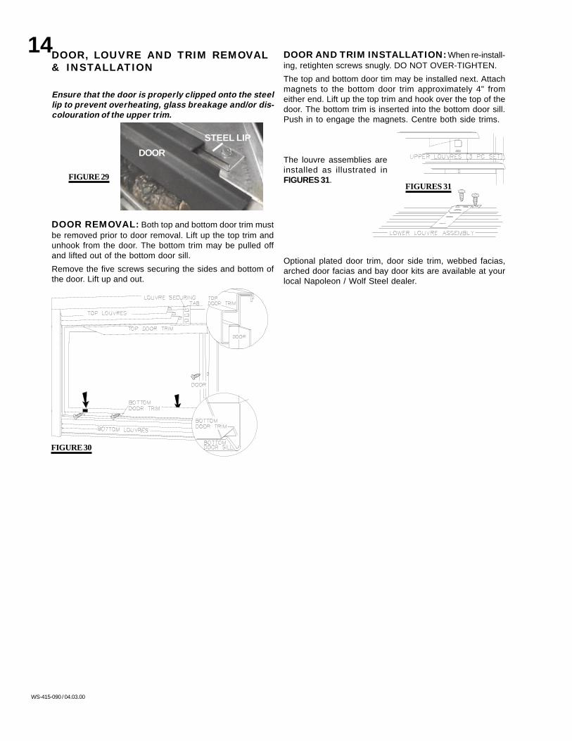
DOOR AND TRIM INSTALLATION: When re-install-ing, retighten screws snugly. DO NOT OVER-TIGHTEN.
The top and bottom door tim may be installed next. Attachmagnets to the bottom door trim approximately 4" fromeither end. Lift up the top trim and hook over the top of thedoor. The bottom trim is inserted into the bottom door sill.Push in to engage the magnets. Centre both side trims.
The louvre assemblies areinstalled as illustrated inFIGURES 31.
Optional plated door trim, door side trim, webbed facias,arched door facias and bay door kits are available at yourlocal Napoleon / Wolf Steel dealer.
DOOR, LOUVRE AND TRIM REMOVAL& INSTALLATION
Ensure that the door is properly clipped onto the steellip to prevent overheating, glass breakage and/or dis-colouration of the upper trim.
DOOR REMOVAL: Both top and bottom door trim mustbe removed prior to door removal. Lift up the top trim andunhook from the door. The bottom trim may be pulled offand lifted out of the bottom door sill.
Remove the five screws securing the sides and bottom ofthe door. Lift up and out.
FIGURE 29
FIGURE 30
FIGURES 31
DOOR
STEEL LIP

15
WS-415-090 / 04.03.00
INSTALLATION TO BE DONE BY A QUALIFIED IN-STALLER and must be electrically connected andgrounded in accordance with local codes. In the absenceof local codes, use the current CSA C22.1 CANADIAN ELECTRI-CAL CODE in Canada or the ANSI/NFPA 70-1996 NATIONAL ELEC-TRICAL CODE in the United States
If the fireplace was not previously equipped with ablower: route a grounded 2-wire, 60hz power cable to thereceptacle / junction box. At this point, it must be strainrelieved and insulated.
The three slots in themounting bracketallow ease of adjust-ment when attachingthe blower. For aquiet running blower,do not allow the as-sembly to sit on thefirebox base.
Slide the vibration reducing pad (A) into the clip (C) andonto the threaded stud (B) at the other end, piercing a holeinto the pad. The blower must be able to be positionedentirely onto the pad.
Tilt the blower onto its side. Slide it past the controls andinto the clip (C). Secure to the threaded stud using the lockwasher and wing nut provided. Ensure that the blowerdoes not touch the fireplace base or the firebox.
C
NOTE OFFSET
FIGURE 33
red
white
black
FIGURE 32
FIGURE 37
RECEPTACLE /
THERMODISC
GROUNDSCREW
JUNCTION BOX
FIGURE 36
Attach the connectors from the black and white wires to thethermodisc and secure the thermodisc bracket to the se-curing stud at the bottom left of the unit using a lock washerand wing nut. Ensure that the thermodisc touches the fire-box wall.
Attach the connectors from the black and red wires to theblower.
Attach and secure the variable speed switch using the nutprovided. Plug the harness cord into the receptacle.
OPTIONAL BLOWER INSTALLATION
FIGURE 35FIGURE 34
CC
A
B
The wire harness provided in this kit is a universalharness. When installed, ensure that any excesswire is contained, preventing it from making con-tact with moving or hot objects.
Drywall dust will penetrate into the blower bear-ings, causing irreparable damage. Care must betaken to prevent drywall dust from coming intocontact with the blower or its compartment. Anydamage resulting from this condition is not cov-ered by the warranty policy.
Because the blower is thermally activated, whenturned on, it will automatically start approximately10 minutes after lighting the fireplace and will runfor approximately 30-45 after the fireplace hasbeen turned off. Use of the fan increases the out-put of heat.

16
WS-415-090 / 04.03.00
If the fireplace was not previously equipped with a fan:route a grounded 2-wire, 60hz power cable to the junctionbox. At this point, it must be strain relieved and insulated.
The wire harness provided in this kit is a universal har-ness. When installed, ensure that any excess wire is con-tained, preventing it from making contact with moving orhot objects.
Position the vibration reducingpad into the clip and onto thethreaded stud at the other end,piercing a hole into the pad.The fan assembly must beable to be positioned entirelyonto the pad.
Slide the fan assembly pastthe controls and and into theclip. Secure using the lockwasher and nut provided.
Attach the connectors from the black and white wires to thethermodisc and secure the thermodisc bracket to the se-curing stud at the bottom left of the unit using a lock washerand wing nut. Ensure that the thermodisc touches the fire-box wall.
RECEPTACLE /JUNCTION BOX
SLOTSOPEN ENDED
VARIABLE SPEED/
BRACKETPIEZO IGNITOR
OPTIONAL THERMOSTATIC SENSOR
JUNCTION BOX
THERMODISC
SENSOR ASSEMBLYBRACKET
RECEPTACLE /
FIGURE 39FIGURE 38
FIGURE 40
FIGURE 41
ELECTRICAL INSTALLATION TO BE DONE BY A QUALI-FIED INSTALLER and must be connected and groundedin accordance with local codes. In the absence of localcodes, use the current CSA C22.1 CANADIAN ELECTRICAL CODE inCanada or the ANSI/NFPA 70-1996 NATIONAL ELECTRICAL CODE
in the United States.
OPTIONAL FAN INSTALLATION
THERMOSTATIC SENSOR CONTROLThis otional kit is meant to be used only in conjunction withthe GD65 Fan Kit, shown above, which may be orderedfrom your Wolf Steel / Napoleon dealer.
With the thermostatic sensor option, the fan, when turnedon, becomes thermally activated, and will automaticallyrun approximately 10 minutes after the fireplace has beenlit and for approximately 30-45 minutes after the fireplacehas been turned off.
Use of the fan increases the output of heat.
Unplug the power cord from the receptacle. Connect allwires as shown.
Attach and secure the sensor assembly bracket to the se-curing stud located next to the receptacle/junction box atthe bottom left of the unit using the lock washer and wingnut. Ensure that the thermodisc touches the firebox wall.
Plug the power cord back into the receptacle.
When installed, ensure that any excess wire is contained,preventing it from making contact with moving or hot ob-jects.

17
WS-415-090 / 04.03.00
WHAT TO DO IF YOU SMELL GAS:
• Turn off all gas to the fireplace.
• Open windows.
• Do not try to light any appliance.
• Do not touch any electric switch; do not use any phonein your building.
• Immediately call your gas supplier from a neighbour'sphone. Follow the gas supplier's instructions.
• If you cannot reach your gas supplier, call the fire de-partment.
FOR YOUR SAFETY READ BEFORE LIGHTING:
A. This fireplace is equipped with a pilot which must be litby hand while following these instructions exactly.
B. Before operating smell all around the fireplace area forgas and next to the floor because some gas is heavierthan air and will settle on the floor.
C. Use only your hand to turn the gas control knob. Neveruse tools. If the knob will not turn by hand, do not try torepair it. Call a qualified service technician. Force or at-tempted repair may result in a fire or explosion.
D. Do not use this fireplace if any part has been underwater. Immediately call a qualified service technician toinspect the fireplace and replace any part of the controlsystem and any gas control which has been under water.
5. Turn gas knob counter-clockwise to pilot.6. Depress slightly and hold gas knob while lighting thepilot with the push button ignitor. Keep knob depressed forone minute, then release. If pilot does not continue to burn,repeat steps 3 through 5.7. With pilot lit, depress and turn gas knob counter-clock-wise to on.8. If equipped with remote on-off switch/thermostat, mainburner may not come on when youturn valve to on. Remote switchmust be in the on position to igniteburner.9. Turn on all electric power to the fireplace.
2. Push in gas control knob slightly and turn clock-wise to off. Do not force.
TO TURN OFF GAS
1. Turn off all electric power to the fireplace if service is tobe performed.
P
I
NO
L
O
T
FFO
GAS KNOB
FLAME ADJUSTMENT
KNOB
OT PIL
LO
IHT P
I
L
O
N O
FF O
PILOT ON/OFFKNOB
OPERATION / MAINTENANCEweather season, the fireplace may emit a slight odour for afew hours. This is caused by dust particles in the heat ex-changer burning off. In both cases, open a window to suffi-ciently ventilate the room. Purge the gas line with the glassdoor removed. Assure that a continuous gas flow is atthe burner before re-installing the door.
OPERATING INSTRUCTIONSWhen lit for the first time, the fireplace will emit a slightodour for a few hours. This is a normal temporary condi-tion caused by the curing of the logs and the "burn-in" ofinternal paints and lubricants used in the manufacturingprocess and will not occur again. After extended periods ofnon-operation such as following a vacation or a warm
LIGHTING INSTRUCTIONS
WARNING: The gas valve has an interlock device whichwill not allow the pilot burner to be lit until the thermo-couple has cooled. Allow approximately 60 seconds forthe thermocouple to cool.
When lighting and re-lighting, the gas knob cannot be turnedfrom pilot to off unless the knob is depressed slightly.
1. Stop! Read the above safety information on this label.2. Turn off all electric power to the fireplace.3. Turn the gas knob clockwise to off.4. Wait five (5) minutes to clear out any gas. If you smellgas including near the floor. Stop! Follow "B" in the abovesafety information on this label. If you don't smell gas go thenext step.
3. Check to see that all burner ports are burning. Clean outany of the ports which may not be burning or are not burningproperly.
4. Check to see that the pilot flame is large enough to engulfthe thermocouple and thermopile and reaches toward theburner with the third jet.
5. Replace the cleaned logs.
6. Check to see that the main burner ignites completely onall openings when the gas knob for the burner is turned on.A 5 to 10 second total light-up period is satisfactory. If ignitiontakes longer, consult your Napoleon dealer / distributor.
7. Check that the gasketing on the sides, top and bottom ofthe door is not broken or missing. Replace if necessary.
MAINTENANCETURN OFF THE GAS AND ELECTRICAL POWERBEFORE SERVICING THE FIREPLACE.
CAUTION: Label all wires prior to disconnection when ser-vicing controls. Wiring errors can cause improper and dan-gerous operation. Verify proper operation after servicing. Thisfireplace and its venting system should be inspected be-fore use and at least annually by a qualified service person.The fireplace area must be kept clear and free of combus-tible materials, gasoline or other flammable vapours andliquids. The flow of combustion and ventilation air must notbe obstructed.
1. In order to properly clean the burner and pilot assembly,remove the logs to expose both assemblies.
2. Keep the control compartment, logs, burner, air shutteropening and the area surrounding the logs clean by vacu-uming or brushing, at least once a year.

18
WS-415-090 / 04.03.00
ADJUSTMENTSPILOT BURNER ADJUSTMENTAdjust the pilot screw to provide properly sized flame. Turnin a clockwise direction to reduce the gas flow.
FLAME MUST ENVELOPUPPER 3/8" TO 1/2" OFTHERMOCOUPLE & THERMOPILE
PILOTTHERMOPILE
BURNER
ELECTRODE
THERMO-COUPLE
FIGURE 43
P
I
PI
PILOT SCREW
LOT
N O
L
O
T
HI
LO
FF O
FIGURE 42
FIGURE 44
FIGURE 45
RESTRICTOR
BAFFLE PLATE
PLATE
VENTURI ADJUSTMENTNatural gas models have air shutters set at 1/16 (.063)inch open. Propane gas models have air shutters set at ¼(.250) inch open. Closing the air shutter will cause a moreyellow flame, but can lead to carboning. Opening the airshutter will cause a more blue flame, but can cause flamelifting from the burner ports. The flame may not appearyellow immediately; allow 15 to 30 minutes for the finalflame colour to be established.
AIR SHUTTER ADJUSTMENT MUST ONLY BE DONE BY AQUALIFIED GAS INSTALLER!
RESTRICTING VERTICAL VENTS: Vertical installa-tions running longer than 10 feet may display a very activeflame. If this appearance is not desirable, remove the baffleplate from the rear wall of the firebox, exposing the flue gasoutlet opening. Bend the restrictor plate up into the flueopening. Replace the baffle plate. This reduces the velocityof the exhaust gases, slowing down the flame pattern andcreating a more traditional gentle appearance. Specific in-structions are shown in "Trouble Shooting".

19
WS-415-090 / 04.03.00
PILOT
P
I
N OIL
O
T
H
LO
FF O
WS-135-053
WS-135-055
WS-135-056
WS-135-054
REPLACEMENTSORDERING REPLACEMENT PARTSContact your dealer or the factory for questions concerning prices and policies on replacement parts. Normally all partscan be ordered through your Napoleon dealer or distributor. When ordering replacement parts always give the followinginformation:
1. MODEL & SERIAL NUMBER OF FIREPLACE 3. PART NUMBER 5. FINISH
2. INSTALLATION DATE OF FIREPLACE 4. DESCRIPTION OF PART
REPLACEMENT PARTS FORFORFORFORFOR WWWWWARRANTYARRANTYARRANTYARRANTYARRANTY REPLAREPLAREPLAREPLAREPLACEMENTCEMENTCEMENTCEMENTCEMENT PPPPPARARARARARTSTSTSTSTS,,,,, AAAAA PHOPHOPHOPHOPHOTTTTTOCOPYOCOPYOCOPYOCOPYOCOPY OFOFOFOFOF THETHETHETHETHE
ORIGINALORIGINALORIGINALORIGINALORIGINAL INVOICEINVOICEINVOICEINVOICEINVOICE WILLWILLWILLWILLWILL BEBEBEBEBE REQUIREDREQUIREDREQUIREDREQUIREDREQUIRED TOTOTOTOTO HONOURHONOURHONOURHONOURHONOUR THETHETHETHETHE CLAIMCLAIMCLAIMCLAIMCLAIM.....
PART NO. DESCRIPTIONGD-225.36 BLACK DOOR FRAMEWS-300-20 GLASS ONLYGD-010.402 GLASS c/w GASKETGD-321-K BLACK DOOR C/W GLASSGD-562.09 DOOR GASKET (100 INCHES)WS-455-11 #40 NATURAL GAS ORIFICEWS-455-033 #53 PROPANE GAS ORIFICEWS-357-01 PIEZO IGNITERWS-680-04 THERMOPILEWS-680-05 THERMOCOUPLEWS-100-38 NATURAL GAS PILOT ASSEMBLYWS-100-39 PROPANE GAS PILOT ASSEMBLYGD-715.136 TOP DOOR TRIMGD-010.376 BOTTOM DOOR TRIMGD-715.11 POLISHED BRASS UPPER LOUVREGD-010.391 POLISHED BRASS LOWER LOUVRE ASSEMBLYWS573-008 HIGH TEMPERATURE SEALANTWS-135-053 BACK LOGWS-135-054 FRONT LOGWS-135-056 RIGHT LOGWS-135-055 LEFT LOGGL-617 LOG SET ASSEMBLYWS-100-35 BURNERWS-660-5 ON/OFF TOGGLE SWITCHWS-455-23 #51 NATURAL GAS PILOT ORIFICEWS-455-24 #30 PROPANE GAS PILOT ORIFICEWS-725-25 NATURAL GAS VALVEWS-725-26 PROPANE GAS VALVEWS-750-09 IGNITER WIREWS385-33 NAPOLEON LOGOWS-430-001 CERAMIC MAGNETGD-020.042 PKG OF 5 DOOR SCREWSGD660 STANDARD WALL SWITCH & 20FT OF WIRE
FLEXIBLE VENT KITSGD220 (5 FT)PART NO. DESCRIPTIONGD-010.397 4" FLEXIBLE ALUMINUM LINER-(5 FT) C/W SPACERS
WS-410-17 7" FLEXIBLE ALUMINUM LINER -(5 FT)
GD330 (10 FT)PART NO. DESCRIPTIONWS-410-018 7" FLEXIBLE ALUMINUM LINER -(10 FT)GS10.300 4" FLEXIBLE ALUMINUM LINER - (10 FT) C/W SPACERS
GD10.370 WALL SUPPORT ASSEMBLY
20
WS-415-090 / 04.03.00
GZ550-1-KT
GD36GD65
GD320B-KT
GD-780KT
GD250K
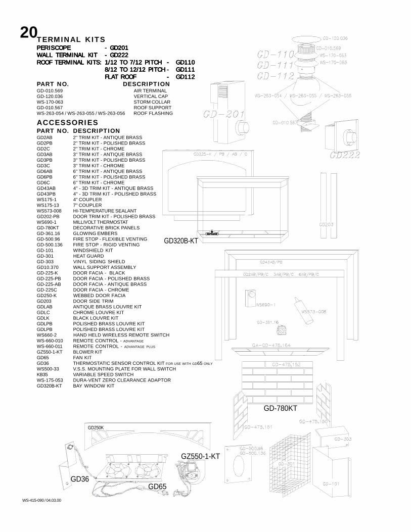
TERMINAL KITSPERISCOPEPERISCOPEPERISCOPEPERISCOPEPERISCOPE - GD201- GD201- GD201- GD201- GD201WALL TERMINAL KITWALL TERMINAL KITWALL TERMINAL KITWALL TERMINAL KITWALL TERMINAL KIT - GD222- GD222- GD222- GD222- GD222ROOF TERMINAL KITS:ROOF TERMINAL KITS:ROOF TERMINAL KITS:ROOF TERMINAL KITS:ROOF TERMINAL KITS: 1/12 TO 7/12 PITCH1/12 TO 7/12 PITCH1/12 TO 7/12 PITCH1/12 TO 7/12 PITCH1/12 TO 7/12 PITCH ----- GD110GD110GD110GD110GD110
8/12 TO 12/12 PITCH8/12 TO 12/12 PITCH8/12 TO 12/12 PITCH8/12 TO 12/12 PITCH8/12 TO 12/12 PITCH ----- GD111GD111GD111GD111GD111FLAFLAFLAFLAFLAT ROOFT ROOFT ROOFT ROOFT ROOF ----- GD112GD112GD112GD112GD112
PART NO. DESCRIPTIONGD-010.569 AIR TERMINALGD-120.036 VERTICAL CAPWS-170-063 STORM COLLARGD-010.567 ROOF SUPPORTWS-263-054 / WS-263-055 / WS-263-056 ROOF FLASHING
ACCESSORIESPART NO. DESCRIPTIONGD2AB 2" TRIM KIT - ANTIQUE BRASSGD2PB 2" TRIM KIT - POLISHED BRASSGD2C 2" TRIM KIT - CHROMEGD3AB 3" TRIM KIT - ANTIQUE BRASSGD3PB 3" TRIM KIT - POLISHED BRASSGD3C 3" TRIM KIT - CHROMEGD6AB 6" TRIM KIT - ANTIQUE BRASSGD6PB 6" TRIM KIT - POLISHED BRASSGD6C 6" TRIM KIT - CHROMEGD43AB 4" - 3D TRIM KIT - ANTIQUE BRASSGD43PB 4" - 3D TRIM KIT - POLISHED BRASSWS175-1 4" COUPLERWS175-13 7" COUPLERWS573-008 HI-TEMPERATURE SEALANTGD202-PB DOOR TRIM KIT - POLISHED BRASSWS690-1 MILLIVOLT THERMOSTATGD-780KT DECORATIVE BRICK PANELSGD-361.16 GLOWING EMBERSGD-500.96 FIRE STOP - FLEXIBLE VENTINGGD-500.136 FIRE STOP - RIGID VENTINGGD-101 WINDSHIELD KITGD-301 HEAT GUARDGD-303 VINYL SIDING SHIELDGD10.370 WALL SUPPORT ASSEMBLYGD-225-K DOOR FACIA - BLACKGD-225-PB DOOR FACIA - POLISHED BRASSGD-225-AB DOOR FACIA - ANTIQUE BRASSGD-225C DOOR FACIA - CHROMEGD250-K WEBBED DOOR FACIAGD203 DOOR SIDE TRIMGDLAB ANTIQUE BRASS LOUVRE KITGDLC CHROME LOUVRE KITGDLK BLACK LOUVRE KITGDLPB POLISHED BRASS LOUVRE KITGDLPB POLISHED BRASS LOUVRE KITWS660-2 HAND HELD WIRELESS REMOTE SWITCHWS-660-010 REMOTE CONTROL - ADVANTAGE
WS-660-011 REMOTE CONTROL - ADVANTAGE PLUS
GZ550-1-KT BLOWER KITGD65 FAN KITGD36 THERMOSTATIC SENSOR CONTROL KIT FOR USE WITH GD65 ONLY
WS500-33 V.S.S. MOUNTING PLATE FOR WALL SWITCHKB35 VARIABLE SPEED SWITCHWS-175-053 DURA-VENT ZERO CLEARANCE ADAPTORGD320B-KT BAY WINDOW KIT

21
WS-415-090 / 04.03.00
TROUBLE SHOOTING GUIDEBEFORE ATTEMPTING TO TROUBLESHOOT, PURGE YOUR UNIT AND INITIALLY LIGHT THE PILOT AND THE MAIN BURNER WITH THE GLASS DOOR REMOVED.
TEST SOLUTIONSYMPTOM PROBLEM
Main burner goesout; pilot stays on.
Pilot flame is not largeenough or not engulfing thethermopile
- turn up pilot flame.
- replace pilot assembly.
Thermopile shorting - clean thermopile connection to the valve. Reconnect.
- replace thermopile / valve.
Remote wall switch wire istoo long; too much resis-tance in the system.
- shorten wire to correct length or wire gauge.
Faulty thermostat or switch. - replace.
Main burner goesout; pilot goes out.
Refer to "MAIN BURNER GOES OUT; PILOT STAYS ON"
Vent is blocked
Vent is re-circulating
- check for vent blockage.
- check joint seals and installation.
4" flexible vent has becomedisconnected from fireplace.
- re-attach to fireplace.
Pilot goes out whenthe gas knob is re-leased.
The gas valve hasan interlock devicewhich will not allowthe pilot burner tobe lit until the ther-mocouple hascooled. Allow ap-proximately 60seconds for thethermocouple tocool.
System is not correctlypurged.
- purge the gas line with the glass door removed.
Out of propane gas. - fill the tank.
Pilot flame is not largeenough
- turn up the pilot flame.
- gently twist the pilot head to improve the flame pattern around thethermocouple.
Pilot flame is not engulfingthe thermocouple.
Thermocouple shorting /faulty.
- loosen and tighten thermocouple.- clean thermocouple and valve connection.- replace thermocouple.- replace valve.
Faulty valve. - replace.
Pilot burning; nogas to mainburner; gas knobis on 'HI'; wallswitch / thermostatis on.
Themostat or switch is de-fective.
- connect a jumper wire across the wall switch terminals; if mainburner lights, replace switch / thermostat.
Main burner orifice is plugged. - remove stoppage in orifice.
Faulty valve. - replace.
Wall switch wiring is defec-tive.
- disconnect switch wires from valve & connect a jumper wire acrossterminals 1 & 3; if the main burner lights, check the wires for defectsand / or replace wires.
PILOTTHERMOPILE
BURNER
ELECTRODE
THERMO-COUPLE
Pilot will not light. - check if pilot can be lit by a match- check that the wire is connected to the push button ignitor.- check if the push button ignitor needs tightening.- replace the wire if the wire insulation is broken or frayed.- replace the electrode if the ceramic insulator is cracked or broken.- replace the push button ignitor.
No spark at pilot burner
- fill the tank.Out of propane gasSpark gap is incorrect - spark gap should be 0.150" to 0.175" (5/32" to 11/64" approx.) from
the electrode tip and the pilot burner. To ensure proper electrodelocation, tighten securing nut (finger tight plus 1/4 turn).
No gas at the pilot burner - check that the manual valve is turned on.- check the pilot orifice for blockage.- replace the valve.- call the gas distributor.
22
WS-415-090 / 04.03.00
Main burner flameis a blue, lazy,transparent flame.
Blockage in vent. - remove blockage. In really cold conditions, ice buildup may occuron the terminal and should be removed as required.
- refer to Figure 16 to ensure correct location of storm collars.Incorrect installation.
TEST SOLUTIONPROBLEMSYMPTOM
Remote wallswitch is in "OFF"position; mainburner comes onwhen gas knob isturned to "ON" po-sition.
Wall switch is mounted up-side down
- reverse.
Faulty valve. - replace.
- replace.Remote wall switch isgrounding.
- check for ground (short); repair ground or replace wire.Remote wall switch wire isgrounding.
Exhaust fumessmelled in room,headaches.
Fireplace is spilling. - check door seal and relief flap seal.- check for chimney blockage- check that chimney is installed to building code.- room is in negative pressure; increase fresh air supply.
White / grey filmforms.
Sulphur from fuel is being de-posited on glass, logs orcombustion chamber sur-faces.
- clean the glass with a recommended gas fireplace glass cleaner.DO NOT CLEAN GLASS WHEN HOT.
If deposits are not cleaned off regularly, the glass may becomepermanently marked.
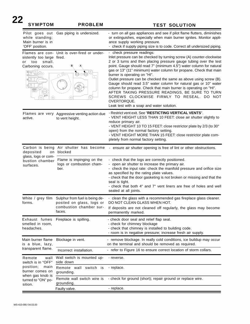
- Restrict vent exit. See "RESTICTING VERTICAL VENTS".- VENT HEIGHT LESS THAN 10 FEET: close air shutter slightly toreduce primary air.- VENT HEIGHT 10 TO 15 FEET: close restrictor plate by 2/3 (to 30°open) from the normal factory setting.- VENT HEIGHT MORE THAN 15 FEET: close restrictor plate com-pletely from normal factory setting.
Aggressive venting action dueto vent height.
Flames are veryactive.
Flames are con-sistently too largeor too small.Carboning occurs.
- check pressure readings:Inlet pressure can be checked by turning screw (A) counter-clockwise2 or 3 turns and then placing pressure gauge tubing over the testpoint. Gauge should read 7" (minimum 4.5") water column for naturalgas or 13" (11" minimum) water column for propane. Check that mainburner is operating on "HI".Outlet pressure can be checked the same as above using screw (B).Gauge should read 3.5" water column for natural gas or 10" watercolumn for propane. Check that main burner is operating on "HI".AFTER TAKING PRESSURE READINGS, BE SURE TO TURNSCREWS CLOCKWISE FIRMLY TO RESEAL. DO NOTOVERTORQUE.Leak test with a soap and water solution.
Unit is over-fired or under-fired.
P
I
AB
PILOT
N O
L
O
T
HI
LO
FF O
Pilot goes outwhile standing;Main burner is in'OFF' position.
Gas piping is undersized. - turn on all gas appliances and see if pilot flame flutters, diminishesor extinguishes, especially when main burner ignites. Monitor appli-ance supply working pressure.- check if supply piping size is to code. Correct all undersized piping.
Carbon is beingdeposited onglass, logs or com-bustion chambersurfaces.
Flame is impinging on thelogs or combustion cham-ber.
- check that the logs are correctly positioned.- open air shutter to increase the primary air.- check the input rate: check the manifold pressure and orifice sizeas specified by the rating plate values.- check that the door gasketing is not broken or missing and that theseal is tight.- check that both 4" and 7" vent liners are free of holes and wellsealed at all joints.
Air shutter has becomeblocked
- ensure air shutter opening is free of lint or other obstructions.

23
WS-415-090 / 04.03.00
NOTES: