GAS-FIRED WALL FURNACE DIRECT VENT … WALL FURNACE DIRECT VENT MILLIVOLT SYSTEM ... over-firing,...
23
WS-415-53 / 04.08.99 GAS-FIRED WALL FURNACE DIRECT VENT MILLIVOLT SYSTEM INSTALLATION AND OPERATION INSTRUCTIONS FOR: NATURAL GAS MODEL GD3200-N / GD3200B-N PROPANE GAS MODEL GD3200-P / GD3200B-P CERTIFIED FOR CANADA AND UNITED STATES USING ANSI / AGA / CGA METHODS INSTALLER: THESE INSTRUCTIONS MUST BE CONVEYED TO AND REMAIN WITH THE HOMEOWNER. CERTIFIED UNDER CANADIAN AND AMERICAN NATIONAL STANDARDS, CSA 2.33 AND ANSI Z21.88 RESPECTIVELY FOR GAS-FIRED VENTED GAS FIRED SPACE HEATING APPLIANCE Fax: (705)722-6031 Email: [email protected] Web: www.napoleon.on.ca Wolf Steel Ltd., RR#1, 9 Napoleon Rd., Barrie, ON., Canada L4M 4Y8 (705)721-1212 R-2000 WARNING: If the information in these instructions is not followed exactly, a fire or explosion may result causing property damage, personal injury or death. FOR YOUR SAFETY Do not store or use gasoline or other flammable vapours and liquids in the vicinity of this or any other appliance. WHAT TO DO IF YOU SMELL GAS: • Do not try to light any appliance. • Do not touch any electrical switch. • Do not use any phone in your building. • Immediately call your gas supplier from a neighbor's phone. Follow the gas supplier's instructions. • If you cannot reach your gas supplier, call the fire department. Installation and service must be performed by a qualified installer, service agency or the gas supplier.
Transcript of GAS-FIRED WALL FURNACE DIRECT VENT … WALL FURNACE DIRECT VENT MILLIVOLT SYSTEM ... over-firing,...
WS-415-53 / 04.08.99
GAS-FIRED WALL FURNACEDIRECT VENT MILLIVOLT SYSTEMINSTALLATION AND OPERATION INSTRUCTIONS FOR:
NATURAL GAS MODEL GD3200-N / GD3200B-NPROPANE GAS MODEL GD3200-P / GD3200B-P
CERTIFIED FOR CANADA AND UNITED STATES USING ANSI / AGA / CGA METHODS
INSTALLER: THESE INSTRUCTIONS MUST BE CONVEYED TO AND REMAIN WITH THE HOMEOWNER.CERTIFIED UNDER CANADIAN AND AMERICAN NATIONAL STANDARDS,
CSA 2.33 AND ANSI Z21.88 RESPECTIVELY FOR GAS-FIRED VENTED GAS FIRED SPACE HEATING APPLIANCE
Fax: (705)722-6031 Email: [email protected]: www.napoleon.on.ca
Wolf Steel Ltd., RR#1, 9 Napoleon Rd.,Barrie, ON., Canada L4M 4Y8 (705)721-1212
R-2000
WARNING: If the information in these instructions is not followed exactly, a fire orexplosion may result causing property damage, personal injury or death.
FOR YOUR SAFETYDo not store or use gasoline or other flammable vapours and liquids in the vicinity of
this or any other appliance.WHAT TO DO IF YOU SMELL GAS:
• Do not try to light any appliance.• Do not touch any electrical switch.• Do not use any phone in your building.
• Immediately call your gas supplier from aneighbor's phone. Follow the gas supplier'sinstructions.• If you cannot reach your gas supplier,call the fire department.
Installation and service must be performed by a qualified installer, service agencyor the gas supplier.
2
WS-415-53 / 04.08.99
TABLE of CONTENTS
PLEASE RETAIN THIS MANUAL FOR FUTURE REFERENCE
PG 2-5 INTRODUCTIONWarrantyGeneral InstructionsGeneral InformationCare of Glass & Plated Parts
5-7 VENTINGVent lengthsSpecial Installation ExampleAir Terminal Locations
8-13 INSTALLATION / FRAMINGWall & Ceiling ProtectionUsing Flexible Vent ComponentsFireplace Vent ConnectionUsing Rigid Vent ComponentsGas InstallationMobile Home InstallationFraming
14-15 FINISHINGLog Placement/Charcoal EmbersDoor, Louvre & Trim Installation
PG 16 OPTIONAL BLOWER INSTALLATION17 OPTIONAL FAN & THERMOSTATIC SENSOR18-19 OPERATION / MAINTENANCE
Operating InstructionsMaintenance
19 ADJUSTMENTSPilot Burner AdjustmentVenturi Adjustment
20-21 REPLACEMENTSOrdering Replacement PartsReplacement PartsAccessoriesVent KitsTerminal Kits
22-23 TROUBLE SHOOTING GUIDE
3
WS-415-53 / 04.08.99
NAPOLEON gas fireplaces are manufactured under the strict Standard of the world recognizedISO9002 Quality Assurance Certificate.
NAPOLEON products are designed with superior components and materials, assembled by trained craftsmen whotake great pride in their work. The burner and valve assembly are leak and test-fired at a quality test station. Thecomplete fireplace is thoroughly inspected by a qualified technician before packaging to ensure that you, the cus-tomer, receives the quality product that you expect from NAPOLEON.
NAPOLEON GAS FIREPLACE PRESIDENT'S LIFETIME LIMITED WARRANTY
The following materials and workmanship in your new NAPOLEON gas fireplace are warranted againstdefects for as long as you own the fireplace. This covers: combustion chamber, heat exchanger, stainless steelburner, phazer™ logs and embers, ceramic glass (thermal breakage only), gold plated parts against tarnishing,porcelainized enamelled components and aluminum extrusion trims.
Electrical (110V and millivolt) components and wearable parts such as blowers, gas valves, thermal switch,switches, wiring, remote controls, ignitor, gasketing, and pilot assembly are covered and NAPOLEON willprovide replacement parts free of charge during the first year of the limited warranty.
Labour related to warranty repair is covered free of charge during the first year. Repair work, however,requires the prior approval of an authorized company official. Labour costs to the account of NAPOLEONare based on a predetermined rate schedule and any repair work must be done through an authorized NAPO-LEON dealer.
CONDITIONS AND LIMITATIONSNAPOLEON warrants its products against manufacturing defects to the original purchaser only -- i.e., the individual or legal entity (registered customer) whose name
appears on the warranty registration card filed with NAPOLEON -- provided that the purchase was made through an authorized NAPOLEON dealer and is subject to thefollowing conditions and limitations:
This factory warranty is nontransferable and may not be extended whatsoever by any of our representatives.The gas fireplace must be installed by a licenced, authorized service technician or contractor. Installation must be done in accordance with the installation instructions
included with the product and all local and national building and fire codes.This limited warranty does not cover damages caused by misuse, lack of maintenance, accident, alterations, abuse or neglect and parts installed from other manufacturers
will nullify this warranty.This limited warranty further does not cover any scratches, dents, corrosion or discolouring caused by excessive heat, abrasive and chemical cleaners nor chipping on
porcelain enamel parts, mechanical breakage of PHAZER™ logs and embers, nor any venting components used in the installation of the fireplace.NAPOLEON warrants its stainless steel burners against defects in workmanship and material for life, subject to the following conditions: During the first 10 years NAPO-
LEON will replace or repair the defective parts at our option free of charge. From 10 years to life, NAPOLEON will provide replacement burners at 50% of the current retailprice.
In the first year only, this warranty extends to the repair or replacement of warranted parts which are defective in material or workmanship provided that the product has beenoperated in accordance with the operation instructions and under normal conditions.
After the first year, with respect to this President's Limited Lifetime Warranty, NAPOLEON may, at its discretion, fully discharge all obligations with respect to this warrantyby refunding to the original warranted purchaser the wholesale price of any warranted but defective part(s).
After the first year, NAPOLEON will not be responsible for installation, labour or any other costs or expenses related to the reinstallation of a warranted part, and suchexpenses are not covered by this warranty.
Notwithstanding any provisions contained in this President's Limited Lifetime Warranty, NAPOLEON’S responsibility under this warranty is defined as above and it shall notin any event extend to any incidental, consequential or indirect damages.
This warranty defines the obligations and liability of NAPOLEON with respect to the NAPOLEON gas fireplace and any other warranties expressed or implied with respectto this product, its components or accessories are excluded.
NAPOLEON neither assumes, nor authorizes any third party to assume, on its behalf, any other liabilities with respect to the sale of this product. NAPOLEON will not beresponsible for: over-firing, downdrafts, spillage caused by environmental conditions such as rooftops, buildings, nearby trees, hills, mountains, inadequate vents or ventila-tion, excessive venting configurations, insufficient makeup air, or negative air pressures which may or may not be caused by mechanical systems such as exhaust fans,furnaces, clothes dryers, etc.
Any damages to fireplace, combustion chamber, heat exchanger, brass trim or other component due to water, weather damage, long periods of dampness, condensation,damaging chemicals or cleaners will not be the responsibility of NAPOLEON.
The bill of sale or copy will be required together with a serial number and a model number when making any warranty claims from your authorized dealer. The warrantyregistration card must be returned within fourteen days to register the warranty.
NAPOLEON reserves the right to have its representative inspect any product or part thereof prior to honouring any warranty claim.
ALL SPECIFICATIONS AND DESIGNS ARE SUBJECT TO CHANGE WITHOUT PRIOR NOTICE DUE TO ON-GOING PRODUCT IMPROVEMENTS. NAPOLEON® IS A REGISTEREDTRADEMARK OF WOLF STEEL LTD. PATENTS U.S. 5.303.693.801 - CAN. 2.073.411, 2.082.915. © WOLF STEEL LTD.
4
WS-415-53 / 04.08.99
Provide adequate ventilation and combustion air. Provide adequate accessibility clearance for servicing and operating the fire-place. Never obstruct the front opening of the fireplace.
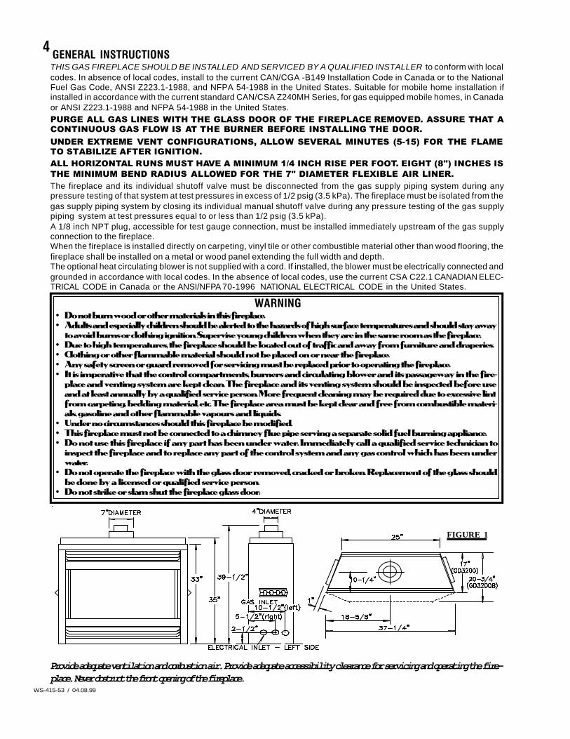
GENERAL INSTRUCTIONSTHIS GAS FIREPLACE SHOULD BE INSTALLED AND SERVICED BY A QUALIFIED INSTALLER to conform with localcodes. In absence of local codes, install to the current CAN/CGA -B149 Installation Code in Canada or to the NationalFuel Gas Code, ANSI Z223.1-1988, and NFPA 54-1988 in the United States. Suitable for mobile home installation ifinstalled in accordance with the current standard CAN/CSA Z240MH Series, for gas equipped mobile homes, in Canadaor ANSI Z223.1-1988 and NFPA 54-1988 in the United States.PURGE ALL GAS LINES WITH THE GLASS DOOR OF THE FIREPLACE REMOVED. ASSURE THAT ACONTINUOUS GAS FLOW IS AT THE BURNER BEFORE INSTALLING THE DOOR.UNDER EXTREME VENT CONFIGURATIONS, ALLOW SEVERAL MINUTES (5-15) FOR THE FLAMETO STABILIZE AFTER IGNITION.ALL HORIZONTAL RUNS MUST HAVE A MINIMUM 1/4 INCH RISE PER FOOT. EIGHT (8") INCHES ISTHE MINIMUM BEND RADIUS ALLOWED FOR THE 7" DIAMETER FLEXIBLE AIR LINER.The fireplace and its individual shutoff valve must be disconnected from the gas supply piping system during anypressure testing of that system at test pressures in excess of 1/2 psig (3.5 kPa). The fireplace must be isolated from thegas supply piping system by closing its individual manual shutoff valve during any pressure testing of the gas supplypiping system at test pressures equal to or less than 1/2 psig (3.5 kPa).A 1/8 inch NPT plug, accessible for test gauge connection, must be installed immediately upstream of the gas supplyconnection to the fireplace.When the fireplace is installed directly on carpeting, vinyl tile or other combustible material other than wood flooring, thefireplace shall be installed on a metal or wood panel extending the full width and depth.The optional heat circulating blower is not supplied with a cord. If installed, the blower must be electrically connected andgrounded in accordance with local codes. In the absence of local codes, use the current CSA C22.1 CANADIAN ELEC-TRICAL CODE in Canada or the ANSI/NFPA 70-1996 NATIONAL ELECTRICAL CODE in the United States.
WARNING• Do not burn wood or other materials in this fireplace.• Adults and especially children should be alerted to the hazards of high surface temperatures and should stay away
to avoid burns or clothing ignition. Supervise young children when they are in the same room as the fireplace.• Due to high temperatures, the fireplace should be located out of traffic and away from furniture and draperies.• Clothing or other flammable material should not be placed on or near the fireplace.• Any safety screen or guard removed for servicing must be replaced prior to operating the fireplace.• It is imperative that the control compartments, burners and circulating blower and its passageway in the fire-
place and venting system are kept clean. The fireplace and its venting system should be inspected before useand at least annually by a qualified service person. More frequent cleaning may be required due to excessive lintfrom carpeting, bedding material, etc. The fireplace area must be kept clear and free from combustible materi-als, gasoline and other flammable vapours and liquids.
• Under no circumstances should this fireplace be modified.• This fireplace must not be connected to a chimney flue pipe serving a separate solid fuel burning appliance.• Do not use this fireplace if any part has been under water. Immediately call a qualified service technician to
inspect the fireplace and to replace any part of the control system and any gas control which has been underwater.
• Do not operate the fireplace with the glass door removed, cracked or broken. Replacement of the glass shouldbe done by a licensed or qualified service person.
• Do not strike or slam shut the fireplace glass door.
FIGURE 1
5
WS-415-53 / 04.08.99
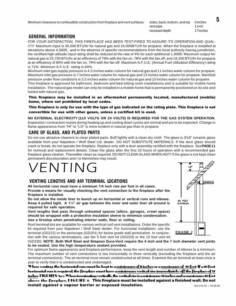
Minimum clearance to combustible construction from fireplace and vent surfaces: sides, back, bottom, and top 0 inchesvent pipe 1 inchrecessed depth 17 inches
GENERAL INFORMATIONFOR YOUR SATISFACTION, THIS FIREPLACE HAS BEEN TEST-FIRED TO ASSURE ITS OPERATION AND QUAL-ITY! Maximum input is 30,000 BTU/hr for natural gas and 24,000BTU/h for propane. When the fireplace is installed atelevations above 4,500ft, and in the absense of specific recommendations from the local authority having jurisdiction,the certified high altitude input rating shall be reduced at the rate of 4% for each additional 1,000ft. Maximum output fornatural gas is 23,700 BTU/hr at an efficiency of 79% with the fan on, 78% with the fan off; and 19,200 BTU/hr for propaneat an efficiency of 80% with the fan on, 79% with the fan off. Maximum A.F.U.E. (Annual Fuel Utilization Efficiency) ratingis 71%. Minimum A.F.U.E. rating is 64%.Minimum inlet gas supply pressure is 4.5 inches water column for natural gas and 11 inches water column for propane.Maximum inlet gas pressure is 7 inches water column for natural gas and 13 inches water column for propane. Manifoldpressure under flow conditions is 3.5 inches water column for natural gas and 10 inches water column for propane.This fireplace is approved for bathroom, bedroom and bed-sitting room installations and is suitable for mobile homeinstallation. The natural gas model can only be installed in a mobile home that is permanently positioned on its site andfueled with natural gas.
This fireplace may be installed in an aftermarket permanently located, manufactured (mobile)home, where not prohibited by local codes.This fireplace is only for use with the type of gas indicated on the rating plate. This fireplace is notconvertible for use with other gases, unless a certified kit is used.NO EXTERNAL ELECTRICITY (110 VOLTS OR 24 VOLTS) IS REQUIRED FOR THE GAS SYSTEM OPERATION.Expansion / contraction nosies during heating up and cooling down cycles are normal and are to be expected. Change inflame appearance from "HI" to "LO" is more evident in natural gas than in propane.
CARE OF GLASS, AND PLATED PARTSDo not use abrasive cleaners to clean plated parts. Buff lightly with a clean dry cloth. The glass is 3/16" ceramic glassavailable from your Napoleon / Wolf Steel Ltd. dealer. DO NOT SUBSTITUTE MATERIALS. If the door glass shouldcrack or break, do not operate the fireplace. Replace only with a door assembly certified with the fireplace. See PAGE 11for removal and replacement details. Clean the glass after the first 10 hours of operation with a recommended gasfireplace glass cleaner. Thereafter clean as required. DO NOT CLEAN GLASS WHEN HOT! If the glass is not kept cleanpermanent discolouration and / or blemishes may result.
VENTING VENTING LENGTHS AND AIR TERMINAL LOCATIONSAll horizontal runs must have a minimum 1/4 inch rise per foot in all cases.Provide a means for visually checking the vent connection to the fireplace after thefireplace is installed.Do not allow the inside liner to bunch up on horizontal or vertical runs and elbows.Keep it pulled tight. A 1¼" air gap between the inner and outer liner all around isrequired for safe operation.Vent lengths that pass through unheated spaces (attics, garages, crawl space)should be wrapped with a protective insulation sleeve to minimize condensation.Use a firestop when penetrating interior walls, floor or ceiling.Roof terminal kits are available for various vertical roof vent installations. Order the specifickit required from your Napoleon / Wolf Steel dealer. For horizontal installation, use theterminal (GD222) or the periscope (GD201) for below grade wall penetration. In conjunc-tion with the various terminations, use the 5 foot vent kit (GD220) or the 10 foot vent kit(GD330). NOTE: Both Wolf Steel and Simpson Dura-Vent require the 4 inch and the 7 inch diameter vent jointsto be sealed. Use the high temperature sealant provided.For optimum flame appearance and fireplace performance, keep the vent length and number of elbows to a minimum.The maximum number of vent connections is two horizontally or three vertically (excluding the fireplace and the airterminal connections). The air terminal must remain unobstructed at all times. Examine the air terminal at least once ayear to verify that it is unobstructed and undamaged.When venting, the horizontal run must be kept to a minimum of 11 inches or a maximum of 20 feet. If a 20 foothorizontal run is required, the fireplace must have a minimum vertical rise immediately off the fireplace of 57inches. FIGURES 3a-c. When terminating vertically, the vertical rise is a minimum 34 inches and a maximum 40 feetabove the fireplace. FIGURE 2. This fireplace must be installed against a finished wall. Do notinstall against a vapour barrier or exposed insulation.
FIGURE 2
6
WS-415-53 / 04.08.99
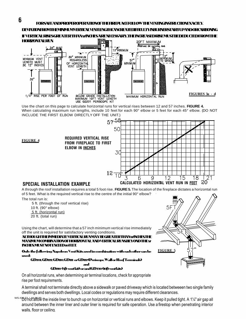
FIGURES 3a - d
Use the chart on this page to calculate horizontal runs for vertical rises between 12 and 57 inches. FIGURE 4.When calculating maximum run lengths, include 10 feet for each 90° elbow or 5 feet for each 45° elbow. (DO NOTINCLUDE THE FIRST ELBOW DIRECTLY OFF THE UNIT.)
FIGURE 4 REQUIRED VERTICAL RISEFROM FIREPLACE TO FIRSTELBOW IN INCHES
CALCULATED HORIZONTAL VENT RUN IN FEETSPECIAL INSTALLATION EXAMPLEA through the roof installation requires a total 5 foot rise. FIGURE 5. The location of the fireplace dictates a horizontal runof 5 feet. What is the required vertical rise to the centre of the initial 90° elbow?The total run is:
5 ft. (through the roof vertical rise)10 ft. (90° elbow) 5 ft. (horizontal run)20 ft. (total run)
Using the chart, will determine that a 57 inch minimum vertical rise immediatelyoff the unit is required for satisfactory venting conditions.ALTHOUGH THE IMMEDIATE VERTICAL RUN MAY BE GREATER THAN 57 INCHES, THEMAXIMUM COMBINATION OF HORIZONTAL AND VERTICAL RUNS, BEYOND THE 57INCHES, MUST NOT EXCEED 20 FEET.
Only the following Napoleon Vent Kits, used in combination with each other can beused:
GD201, GD222, GD110, GD111 or GD112 (Periscope, Wall or Roof Terminals)and
GD220 (5ft vent kit) or/and GD330 (10ft vent kits)
FIGURE 5
On all horizontal runs, when determining air terminal locations, check for appropriaterise per foot requirements.
A terminal shall not terminate directly above a sidewalk or paved driveway which is located betweeen two single familydwellings and serves both dwellings. Local codes or regulations may require different clearances.
Do not allow the inside liner to bunch up on horizontal or vertical runs and elbows. Keep it pulled tight. A 1¼" air gap allaround between the inner liner and outer liner is required for safe operation. Use a firestop when penetrating interiorwalls, floor or ceiling.
FOR SAFE AND PROPER OPERATION OF THE FIREPLACE FOLLOW THE VENTING INSTRUCTION EXACTLY.
DEVIATION FROM THE MINIMUM VERTICAL VENT LENGTH CAN CREATE DIFFICULTY IN BURNER START-UP AND/OR CARBONING.
IF VERTICAL RISES GREATER THAN 57 INCHES ARE NECESSARY, THE INCREASED RISE MUST BE DEDUCTED FROM THEHORIZONTAL RUN.
7
WS-415-53 / 04.08.99
FIGURE 6
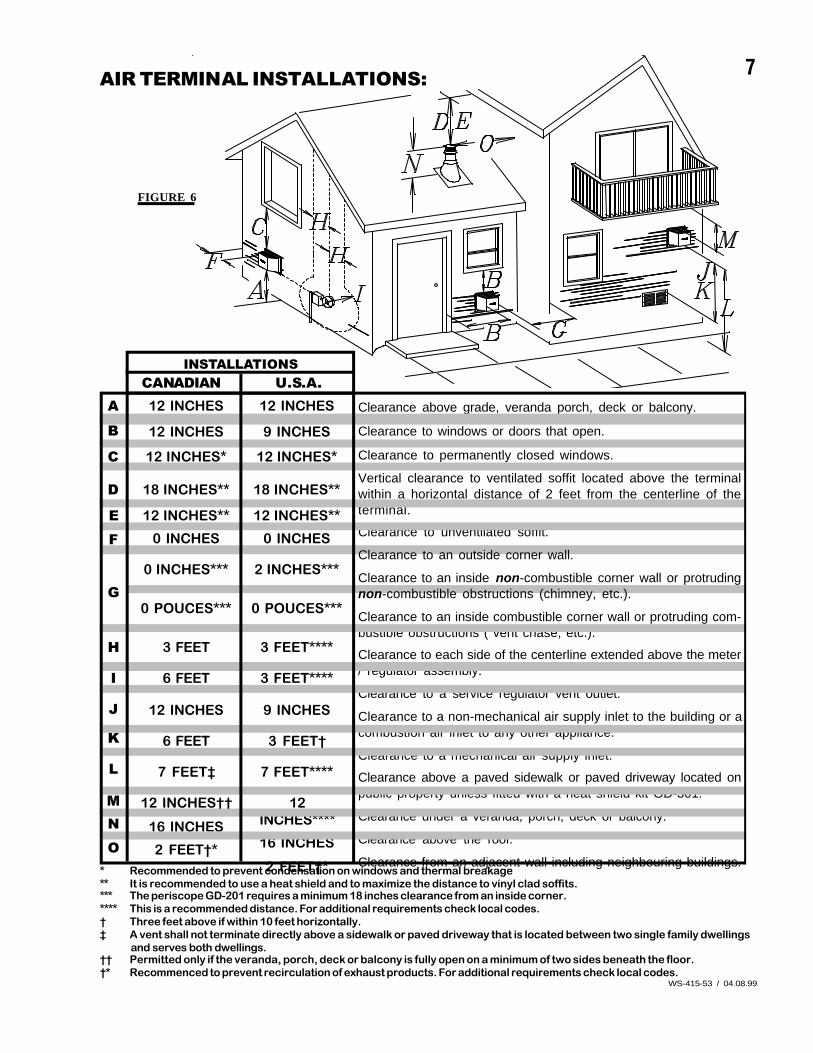
AIR TERMINAL INSTALLATIONS:
* Recommended to prevent condensation on windows and thermal breakage** It is recommended to use a heat shield and to maximize the distance to vinyl clad soffits.*** The periscope GD-201 requires a minimum 18 inches clearance from an inside corner.**** This is a recommended distance. For additional requirements check local codes.† Three feet above if within 10 feet horizontally.‡ A vent shall not terminate directly above a sidewalk or paved driveway that is located between two single family dwellings
and serves both dwellings.†† Permitted only if the veranda, porch, deck or balcony is fully open on a minimum of two sides beneath the floor.†* Recommenced to prevent recirculation of exhaust products. For additional requirements check local codes.
A
B
C
D
EF
G
H
I
J
K
L
MNO
12 INCHES
9 INCHES
12 INCHES*
18 INCHES**
12 INCHES**
0 INCHES
2 INCHES***
0 POUCES***
3 FEET****
3 FEET****
9 INCHES
3 FEET†
7 FEET****
12INCHES****
16 INCHES
2 FEET†*
Clearance above grade, veranda porch, deck or balcony.
Clearance to windows or doors that open.
Clearance to permanently closed windows.
Vertical clearance to ventilated soffit located above the terminalwithin a horizontal distance of 2 feet from the centerline of theterminal.
Clearance to unventilated soffit.
Clearance to an outside corner wall.
Clearance to an inside non-combustible corner wall or protrudingnon-combustible obstructions (chimney, etc.).
Clearance to an inside combustible corner wall or protruding com-bustible obstructions ( vent chase, etc.).
Clearance to each side of the centerline extended above the meter/ regulator assembly.
Clearance to a service regulator vent outlet.
Clearance to a non-mechanical air supply inlet to the building or acombustion air inlet to any other appliance.
Clearance to a mechanical air supply inlet.
Clearance above a paved sidewalk or paved driveway located onpublic property unless fitted with a heat shield kit GD-301.
Clearance under a veranda, porch, deck or balcony.
Clearance above the roof.
Clearance from an adjacent wall including neighbouring buildings.
CANADIAN U.S.A.12 INCHES
12 INCHES
12 INCHES*
18 INCHES**
12 INCHES**
0 INCHES
0 INCHES***
0 POUCES***
3 FEET
6 FEET
12 INCHES
6 FEET
7 FEET‡
12 INCHES††
16 INCHES
2 FEET†*
INSTALLATIONS
8
WS-415-53 / 04.08.99
INSTALL ATIONWALL AND CEILING PROTECTIONFOR SAFE AND PROPER OPERATION OF THE FIREPLACE, FOLLOW THE VENTING INSTRUCTIONS EX-ACTLY.
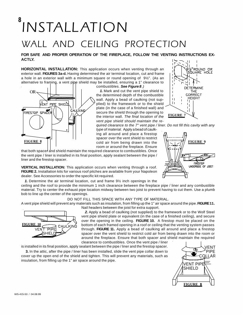
HORIZONTAL INSTALLATION: This application occurs when venting through anexterior wall. FIGURES 3a-d. Having determined the air terminal location, cut and framea hole in an exterior wall with a minimum square or round opening of 9½". (As analternative to framing, a vent pipe shield may be installed, ensuring a 1" clearance to
combustibles. See Figure 8 .)1. Mark and cut the vent pipe shield to
the determined depth of the combustiblewall. Apply a bead of caulking (not sup-plied) to the framework or to the shieldplate (in the case of a finished wall) andsecure the shield through the opening tothe interior wall. The final location of thevent pipe shield should maintain the re-quired clearance to the 7" vent pipe / liner. Do not fill this cavity with anytype of material. Apply a bead of caulk-ing all around and place a firestopspacer over the vent shield to restrictcold air from being drawn into theroom or around the fireplace. Ensure
that both spacer and shield maintain the required clearance to combustibles. Oncethe vent pipe / liner is installed in its final position, apply sealant between the pipe /liner and the firestop spacer.
VERTICAL INSTALLATION: This application occurs when venting through a roof.FIGURE 2. Installation kits for various roof pitches are available from your Napoleondealer. See Accessories to order the specific kit required.
1. Determine the air terminal location, cut and frame 9½ inch openings in theceiling and the roof to provide the minimum 1 inch clearance between the fireplace pipe / liner and any combustiblematerial. Try to center the exhaust pipe location midway between two joist to prevent having to cut them. Use a plumbbob to line up the center of the openings.
DO NOT FILL THIS SPACE WITH ANY TYPE OF MATERIAL.A vent pipe shield will prevent any materials such as insulation, from filling up the 1" air space around the pipe. FIGURE 11.
Nail headers between the joist for extra support.2. Apply a bead of caulking (not supplied) to the framework or to the Wolf Steel
vent pipe shield plate or equivalent (in the case of a finished ceiling), and secureover the opening in the ceiling. FIGURE 10. A firestop must be placed on thebottom of each framed opening in a roof or ceiling that the venting system passesthrough. FIGURE 11. Apply a bead of caulking all around and place a firestopspacer over the vent shield to restrict cold air from being drawn into the room oraround the fireplace. Ensure that both spacer and shield maintain the requiredclearance to combustibles. Once the vent pipe / liner
is installed in its final position, apply sealant between the pipe / liner and the firestop spacer. 3. In the attic, after the pipe / liner has been installed, slide the vent pipe collar down to
cover up the open end of the shield and tighten. This will prevent any materials, such asinsulation, from filling up the 1" air space around the pipe.
FIGURE 8
OR
FIGURE 10
FIGURE 11
VENT PIPESHIELD
VENTPIPE
COLLAR
FIGURE 9
FIGURE 7
9
WS-415-53 / 04.08.99
FIGURE 13
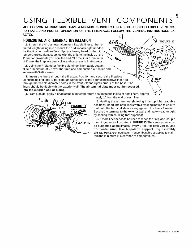
USING FLEXIBLE VENT COMPONENTSALL HORIZONTAL RUNS MUST HAVE A MINIMUM ¼ INCH RISE PER FOOT USING FLEXIBLE VENTING.FOR SAFE AND PROPER OPERATION OF THE FIREPLACE, FOLLOW THE VENTING INSTRUCTIONS EX-ACTLY.
HORIZONTAL AIR TERMINAL INSTALLATION1. Stretch the 4" diameter aluminum flexible liner to the re-
quired length taking into account the additional length neededfor the finished wall surface. Apply a heavy bead of the hightemperature sealant, supplied with the unit, to the inside of the4" liner approximately 1" from the end. Slip the liner a minimumof 2" over the fireplace vent collar and secure with 3 #8 screws.
2. Using the 7" diameter flexible aluminum liner, apply sealant,slide a minimum of 2" over the fireplace combustion air collar andsecure with 3 #8 screws.
3. Insert the liners through the firestop. Position and secure the fireplaceusing the nailing tabs (2 per side) and/or secure to the floor using screws insertedthrough the two ¼" diameter holes in the front left and right corners of the base. Theliners should be flush with the exterior wall. The air teminal plate must not be recessedinto the exterior wall or siding.
4. From outside, apply a bead of the high temperature sealant to the inside of both liners, approxi-mately 1" from the end of each liner.
5. Holding the air terminal (lettering in an upright, readableposition), insert into both liners with a twisting motion to ensurethat both the terminal sleeves engage into the liners / sealant.Secure the terminal to the exterior wall and make weather tightby sealing with caulking (not supplied).
6. If more liner needs to be used to reach the fireplace, couplethem together as illustrated in FIGURE 13. The vent system mustbe supported approximately every 3 feet for both vertical andhorizontal runs. Use Napoleon support r ing assemblyGA-GD-010.370 or equivalent noncombustible strapping to main-tain the minimum 1" clearance to combustibles.
FIGURE 12
10
WS-415-53 / 04.08.99
FIGURE 16
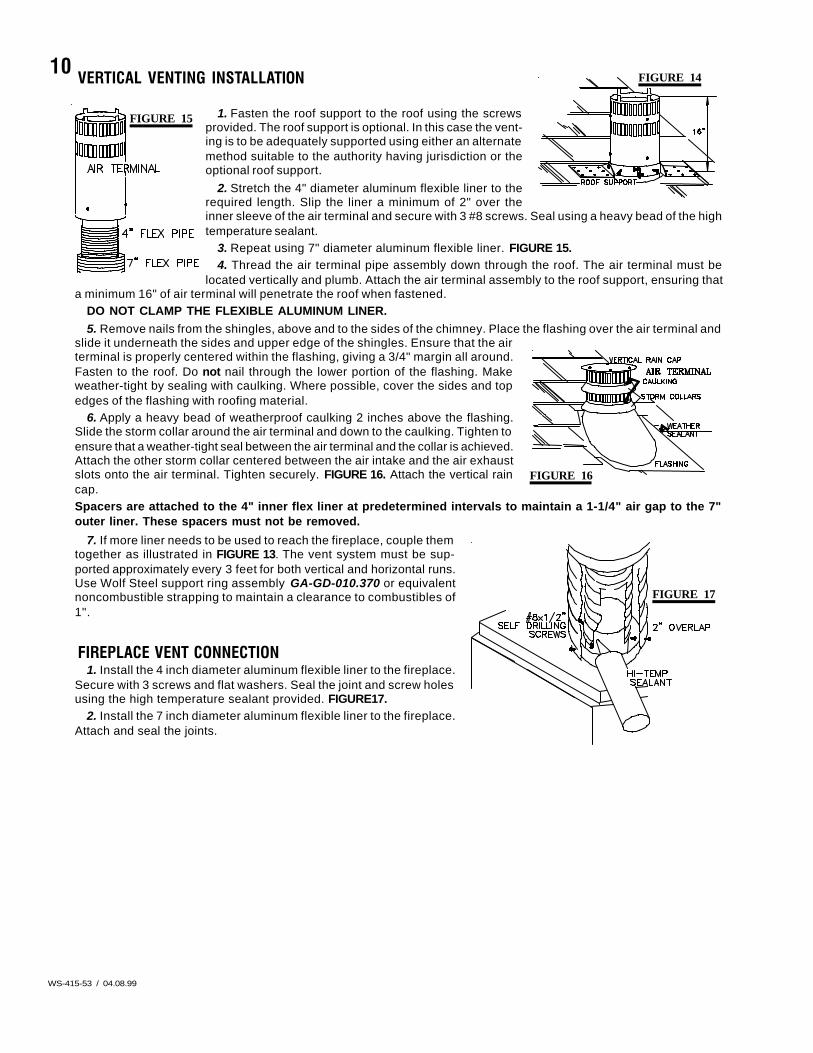
FIGURE 14VERTICAL VENTING INSTALLATION
1. Fasten the roof support to the roof using the screwsprovided. The roof support is optional. In this case the vent-ing is to be adequately supported using either an alternatemethod suitable to the authority having jurisdiction or theoptional roof support.
2. Stretch the 4" diameter aluminum flexible liner to therequired length. Slip the liner a minimum of 2" over theinner sleeve of the air terminal and secure with 3 #8 screws. Seal using a heavy bead of the hightemperature sealant.
3. Repeat using 7" diameter aluminum flexible liner. FIGURE 15.4. Thread the air terminal pipe assembly down through the roof. The air terminal must be
located vertically and plumb. Attach the air terminal assembly to the roof support, ensuring thata minimum 16" of air terminal will penetrate the roof when fastened.
DO NOT CLAMP THE FLEXIBLE ALUMINUM LINER.5. Remove nails from the shingles, above and to the sides of the chimney. Place the flashing over the air terminal and
slide it underneath the sides and upper edge of the shingles. Ensure that the airterminal is properly centered within the flashing, giving a 3/4" margin all around.Fasten to the roof. Do not nail through the lower portion of the flashing. Makeweather-tight by sealing with caulking. Where possible, cover the sides and topedges of the flashing with roofing material.
6. Apply a heavy bead of weatherproof caulking 2 inches above the flashing.Slide the storm collar around the air terminal and down to the caulking. Tighten toensure that a weather-tight seal between the air terminal and the collar is achieved.Attach the other storm collar centered between the air intake and the air exhaustslots onto the air terminal. Tighten securely. FIGURE 16. Attach the vertical raincap.Spacers are attached to the 4" inner flex liner at predetermined intervals to maintain a 1-1/4" air gap to the 7"outer liner. These spacers must not be removed.
7. If more liner needs to be used to reach the fireplace, couple themtogether as illustrated in FIGURE 13. The vent system must be sup-ported approximately every 3 feet for both vertical and horizontal runs.Use Wolf Steel support ring assembly GA-GD-010.370 or equivalentnoncombustible strapping to maintain a clearance to combustibles of1".
FIREPLACE VENT CONNECTION1. Install the 4 inch diameter aluminum flexible liner to the fireplace.
Secure with 3 screws and flat washers. Seal the joint and screw holesusing the high temperature sealant provided. FIGURE17.
2. Install the 7 inch diameter aluminum flexible liner to the fireplace.Attach and seal the joints.
FIGURE 15
FIGURE 17
11
WS-415-53 / 04.08.99
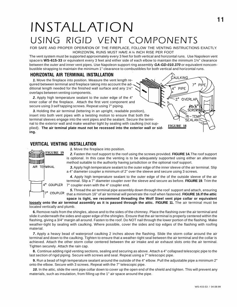
INSTALL ATIONUSING RIGID VENT COMPONENTSFOR SAFE AND PROPER OPERATION OF THE FIREPLACE, FOLLOW THE VENTING INSTRUCTIONS EXACTLY.
HORIZONTAL RUNS MUST HAVE A ¼ INCH RISE PER FOOTThe vent system must be supported approximately every 3 feet for both vertical and horizontal runs. Use Napoleon ventspacers WS-615-33 or equivalent every 3 feet and either side of each elbow to maintain the minimum 1¼" clearancebetween the outer and inner vent pipes. Use Napoleon support ring assembly GA-GD-010.370 or equivalent noncom-bustible strapping to maintain the minimum 1" clearance to combustibles for both vertical and horizontal runs.
HORIZONTAL AIR TERMINAL INSTALLATION1. Move the fireplace into position. Measure the vent length re-
quired between terminal and fireplace taking into account the ad-ditional length needed for the finished wall surface and any 1¼"overlaps between venting components.
2. Apply high temperature sealant to the outer edge of the 4"inner collar of the fireplace. Attach the first vent component andsecure using 3 self tapping screws. Repeat using 7" piping.
3. Holding the air terminal (lettering in an upright, readable position),insert into both vent pipes with a twisting motion to ensure that both theterminal sleeves engage into the vent pipes and the sealant. Secure the termi-nal to the exterior wall and make weather tight by sealing with caulking (not sup-plied). The air teminal plate must not be recessed into the exterior wall or sid-ing.
VERTICAL VENTING INSTALLATION1. Move the fireplace into position.2. Fasten the roof support to the roof using the screws provided. FIGURE 14. The roof support
is optional. In this case the venting is to be adequately supported using either an alternatemethod suitable to the authority having jurisdiction or the optional roof support.
3. Apply high temperature sealant to the outer edge of the inner sleeve of the air terminal. Slipa 4" diameter coupler a minimum of 2" over the sleeve and secure using 3 screws.
4. Apply high temperature sealant to the outer edge of the of the outside sleeve of the airterminal. Slip a 7" diameter coupler over the sleeve and secure as before. FIGURE 19. Trim the7" coupler even with the 4" coupler end.
5. Thread the air terminal pipe assembly down through the roof support and attach, ensuringthat a minimum 16" of air terminal will penetrate the roof when fastened. FIGURE 16. If the atticspace is tight, we recommend threading the Wolf Steel vent pipe collar or equivalent
loosely onto the air terminal assembly as it is passed through the attic. FIGURE 11. The air terminal must belocated vertically and plumb.
6. Remove nails from the shingles, above and to the sides of the chimney. Place the flashing over the air terminal andslide it underneath the sides and upper edge of the shingles. Ensure that the air terminal is properly centered within theflashing, giving a 3/4" margin all around. Fasten to the roof. Do NOT nail through the lower portion of the flashing. Makeweather-tight by sealing with caulking. Where possible, cover the sides and top edges of the flashing with roofingmaterial.
7. Apply a heavy bead of waterproof caulking 2 inches above the flashing. Slide the storm collar around the airterminal and down to the caulking. Tighten to ensure that a weather-tight seal between the air terminal and the collar isachieved. Attach the other storm collar centered between the air intake and air exhaust slots onto the air terminal.Tighten securely. Attach the rain cap.
8. Continue adding rigid venting sections, sealing and securing as above. Attach a 4" collapsed telescopic pipe to thelast section of rigid piping. Secure with screws and seal. Repeat using a 7" telescopic pipe.
9. Run a bead of high temperature sealant around the outside of the 4" elbow. Pull the adjustable pipe a minimum 2"onto the elbow. Secure with 3 screws. Repeat with the 7" telescopic pipe.
10. In the attic, slide the vent pipe collar down to cover up the open end of the shield and tighten. This will prevent anymaterials, such as insulation, from filling up the 1" air space around the pipe.
FIGURE 19
FIGURE 18
12
WS-415-53 / 04.08.99
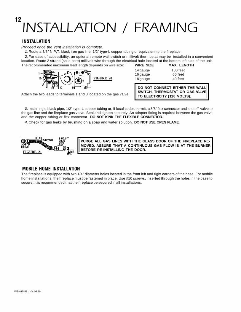
INSTALLATION / FRAMINGINSTALLATIONProceed once the vent installation is complete.
1. Route a 3/8" N.P.T. black iron gas line, 1/2" type-L copper tubing or equivalent to the fireplace.2. For ease of accessibility, an optional remote wall switch or millivolt thermostat may be installed in a convenient
location. Route 2 strand (solid core) millivolt wire through the electrical hole located at the bottom left side of the unit.The recommended maximum lead length depends on wire size: WIRE SIZE MAX. LENGTH
14 gauge 100 feet16 gauge 60 feet18 gauge 40 feet
Attach the two leads to terminals 1 and 3 located on the gas valve.
3. Install rigid black pipe, 1/2" type-L copper tubing or, if local codes permit, a 3/8" flex connector and shutoff valve tothe gas line and the fireplace gas valve. Seal and tighten securely. An adapter fitting is required between the gas valveand the copper tubing or flex connector. DO NOT KINK THE FLEXIBLE CONNECTOR.
4. Check for gas leaks by brushing on a soap and water solution. DO NOT USE OPEN FLAME.
MOBILE HOME INSTALLATIONThe fireplace is equipped with two 1/4" diameter holes located in the front left and right corners of the base. For mobilehome installations, the fireplace must be fastened in place. Use #10 screws, inserted through the holes in the base tosecure. It is recommended that the fireplace be secured in all installations.
DO NOT CONNECT EITHER THE WALLSWITCH, THERMOSTAT OR GAS VALVETO ELECTRICITY (110 VOLTS).
P
I
PI3
1
2
LOT
N O
L
O
THI
LO
FF O
FIGURE 20
PURGE ALL GAS LINES WITH THE GLASS DOOR OF THE FIREPLACE RE-MOVED. ASSURE THAT A CONTINUOUS GAS FLOW IS AT THE BURNERBEFORE RE-INSTALLING THE DOOR.FIGURE 21
13
WS-415-53 / 04.08.99
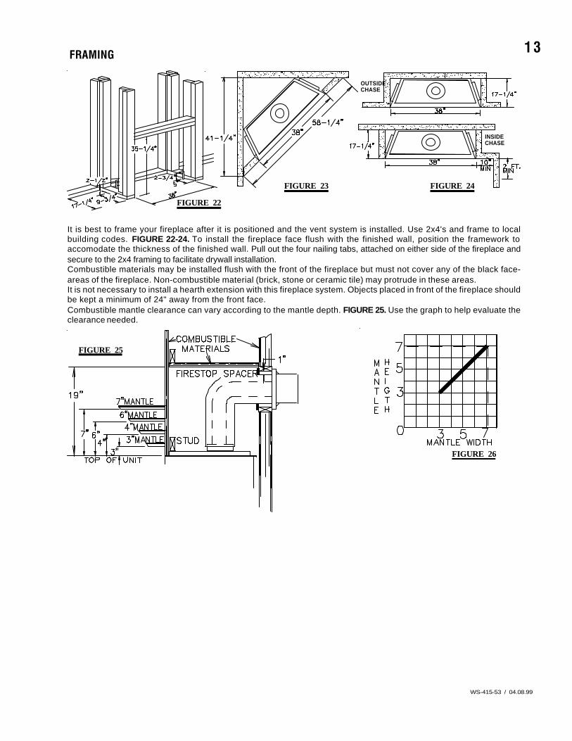
FRAMING
It is best to frame your fireplace after it is positioned and the vent system is installed. Use 2x4's and frame to localbuilding codes. FIGURE 22-24. To install the fireplace face flush with the finished wall, position the framework toaccomodate the thickness of the finished wall. Pull out the four nailing tabs, attached on either side of the fireplace andsecure to the 2x4 framing to facilitate drywall installation.Combustible materials may be installed flush with the front of the fireplace but must not cover any of the black face-areas of the fireplace. Non-combustible material (brick, stone or ceramic tile) may protrude in these areas.It is not necessary to install a hearth extension with this fireplace system. Objects placed in front of the fireplace shouldbe kept a minimum of 24" away from the front face.Combustible mantle clearance can vary according to the mantle depth. FIGURE 25. Use the graph to help evaluate theclearance needed.
OUTSIDECHASE
INSIDECHASE
FIGURE 23 FIGURE 24
FIGURE 22
FIGURE 25
FIGURE 26
14
WS-415-53 / 04.08.99
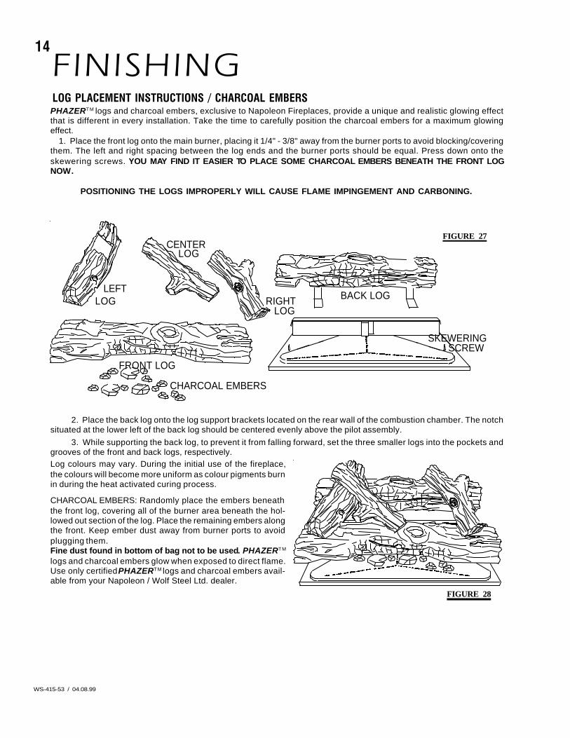
POSITIONING THE LOGS IMPROPERLY WILL CAUSE FLAME IMPINGEMENT AND CARBONING.
BACK LOG
CENTERLOG
CHARCOAL EMBERS
LEFTLOG
FRONT LOG
LOGRIGHT
SCREWSKEWERING
2. Place the back log onto the log support brackets located on the rear wall of the combustion chamber. The notchsituated at the lower left of the back log should be centered evenly above the pilot assembly.
3. While supporting the back log, to prevent it from falling forward, set the three smaller logs into the pockets andgrooves of the front and back logs, respectively.Log colours may vary. During the initial use of the fireplace,the colours will become more uniform as colour pigments burnin during the heat activated curing process.
CHARCOAL EMBERS: Randomly place the embers beneaththe front log, covering all of the burner area beneath the hol-lowed out section of the log. Place the remaining embers alongthe front. Keep ember dust away from burner ports to avoidplugging them.Fine dust found in bottom of bag not to be used. PHAZERTM
logs and charcoal embers glow when exposed to direct flame.Use only certified PHAZERTM logs and charcoal embers avail-able from your Napoleon / Wolf Steel Ltd. dealer.
FIGURE 27
FINISHINGLOG PLACEMENT INSTRUCTIONS / CHARCOAL EMBERSPHAZERTM logs and charcoal embers, exclusive to Napoleon Fireplaces, provide a unique and realistic glowing effectthat is different in every installation. Take the time to carefully position the charcoal embers for a maximum glowingeffect.
1. Place the front log onto the main burner, placing it 1/4" - 3/8" away from the burner ports to avoid blocking/coveringthem. The left and right spacing between the log ends and the burner ports should be equal. Press down onto theskewering screws. YOU MAY FIND IT EASIER TO PLACE SOME CHARCOAL EMBERS BENEATH THE FRONT LOGNOW.
FIGURE 28
15
WS-415-53 / 04.08.99
FIGURE 31
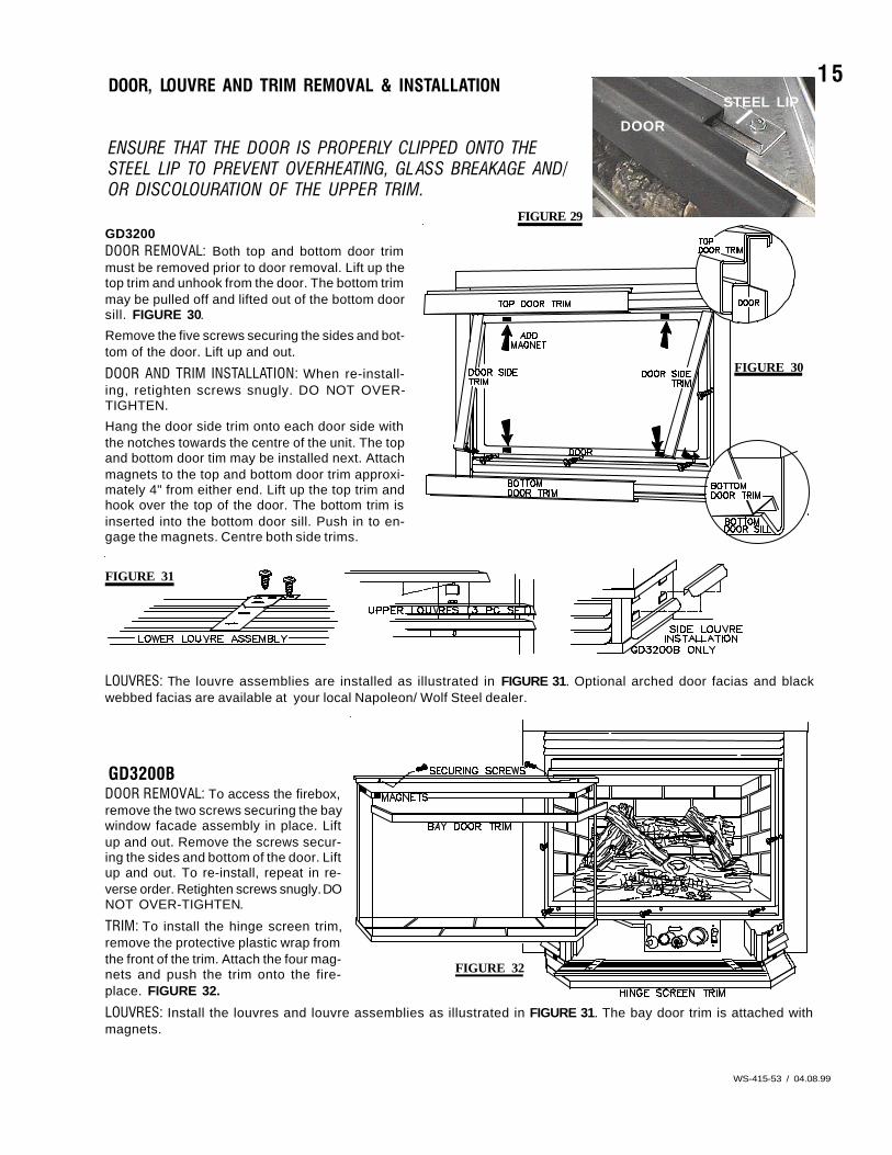
DOOR, LOUVRE AND TRIM REMOVAL & INSTALLATION
ENSURE THAT THE DOOR IS PROPERLY CLIPPED ONTO THESTEEL LIP TO PREVENT OVERHEATING, GL ASS BREAKAGE AND/OR DISCOLOURATION OF THE UPPER TRIM.
GD3200DOOR REMOVAL: Both top and bottom door trimmust be removed prior to door removal. Lift up thetop trim and unhook from the door. The bottom trimmay be pulled off and lifted out of the bottom doorsill. FIGURE 30.
Remove the five screws securing the sides and bot-tom of the door. Lift up and out.
DOOR AND TRIM INSTALLATION: When re-install-ing, retighten screws snugly. DO NOT OVER-TIGHTEN.
Hang the door side trim onto each door side withthe notches towards the centre of the unit. The topand bottom door tim may be installed next. Attachmagnets to the top and bottom door trim approxi-mately 4" from either end. Lift up the top trim andhook over the top of the door. The bottom trim isinserted into the bottom door sill. Push in to en-gage the magnets. Centre both side trims.
LOUVRES: The louvre assemblies are installed as illustrated in FIGURE 31. Optional arched door facias and blackwebbed facias are available at your local Napoleon/ Wolf Steel dealer.
GD3200BDOOR REMOVAL: To access the firebox,remove the two screws securing the baywindow facade assembly in place. Liftup and out. Remove the screws secur-ing the sides and bottom of the door. Liftup and out. To re-install, repeat in re-verse order. Retighten screws snugly. DONOT OVER-TIGHTEN.
TRIM: To install the hinge screen trim,remove the protective plastic wrap fromthe front of the trim. Attach the four mag-nets and push the trim onto the fire-place. FIGURE 32.
LOUVRES: Install the louvres and louvre assemblies as illustrated in FIGURE 31. The bay door trim is attached withmagnets.
FIGURE 30
DOOR
STEEL LIP
FIGURE 29
I H
LO
LP
O FF N
TI O
O
FIGURE 32
16
WS-415-53 / 04.08.99
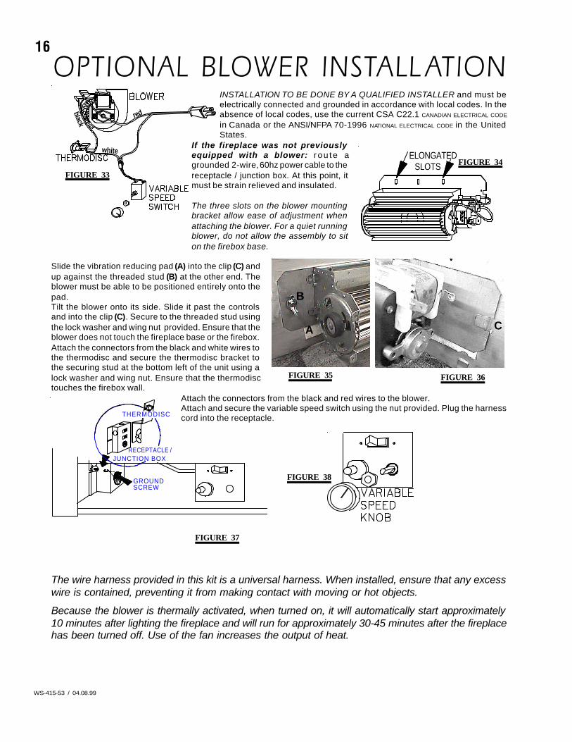
OPTIONAL BLOWER INSTALL ATIONINSTALLATION TO BE DONE BY A QUALIFIED INSTALLER and must beelectrically connected and grounded in accordance with local codes. In theabsence of local codes, use the current CSA C22.1 CANADIAN ELECTRICAL CODE
in Canada or the ANSI/NFPA 70-1996 NATIONAL ELECTRICAL CODE in the UnitedStates.
If the fireplace was not previouslyequipped with a blower: r ou te agrounded 2-wire, 60hz power cable to thereceptacle / junction box. At this point, itmust be strain relieved and insulated.
The three slots on the blower mountingbracket allow ease of adjustment whenattaching the blower. For a quiet runningblower, do not allow the assembly to siton the firebox base.
Slide the vibration reducing pad (A) into the clip (C) andup against the threaded stud (B) at the other end. Theblower must be able to be positioned entirely onto thepad.Tilt the blower onto its side. Slide it past the controlsand into the clip (C). Secure to the threaded stud usingthe lock washer and wing nut provided. Ensure that theblower does not touch the fireplace base or the firebox.Attach the connectors from the black and white wires tothe thermodisc and secure the thermodisc bracket tothe securing stud at the bottom left of the unit using alock washer and wing nut. Ensure that the thermodisctouches the firebox wall.
Attach the connectors from the black and red wires to the blower.Attach and secure the variable speed switch using the nut provided. Plug the harnesscord into the receptacle.
The wire harness provided in this kit is a universal harness. When installed, ensure that any excesswire is contained, preventing it from making contact with moving or hot objects.
Because the blower is thermally activated, when turned on, it will automatically start approximately10 minutes after lighting the fireplace and will run for approximately 30-45 minutes after the fireplacehas been turned off. Use of the fan increases the output of heat.
red
white
black
FIGURE 33
FIGURE 38
RECEPTACLE /
THERMODISC
GROUNDSCREW
JUNCTION BOX
FIGURE 37
CC
FIGURE 36FIGURE 35
A
B
C
FIGURE 34SLOTSELONGATED
17
WS-415-53 / 04.08.99
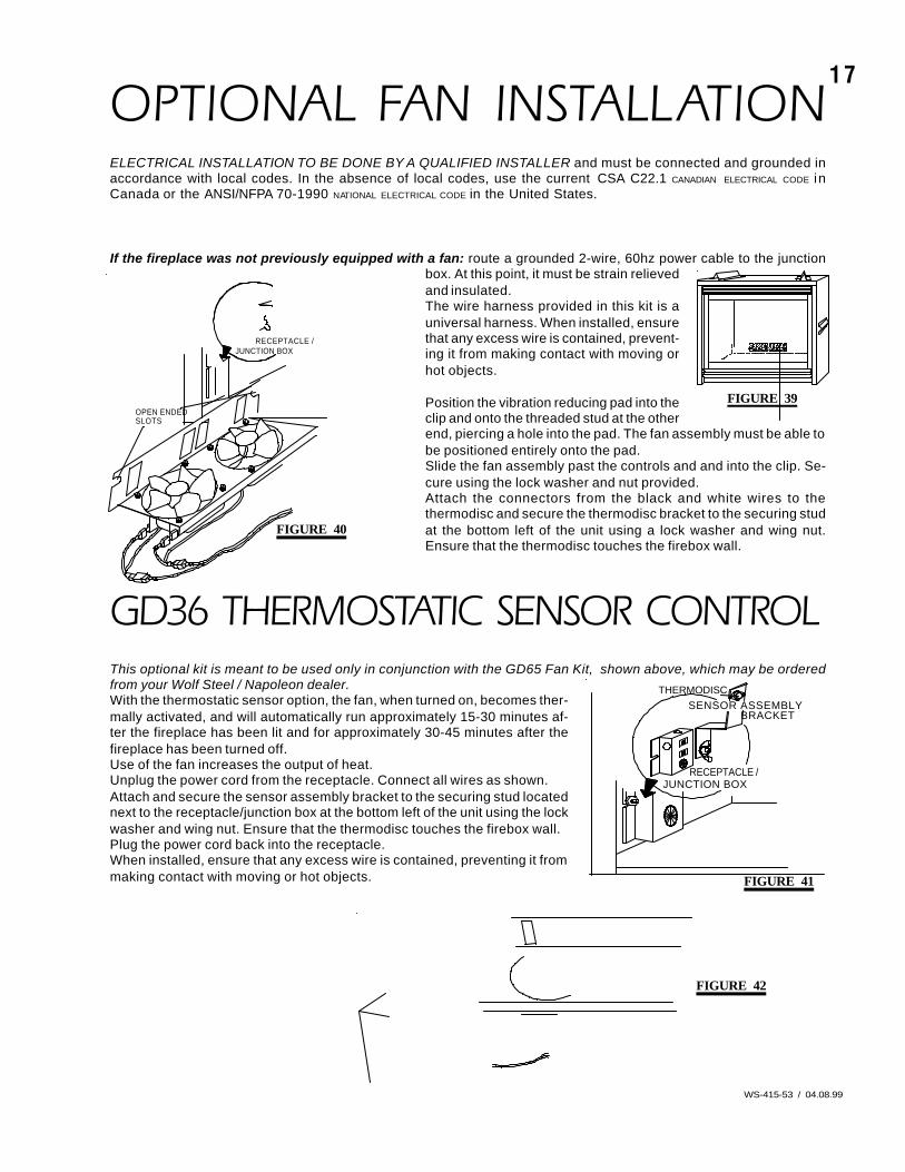
OPTIONAL FAN INSTALLATIONELECTRICAL INSTALLATION TO BE DONE BY A QUALIFIED INSTALLER and must be connected and grounded inaccordance with local codes. In the absence of local codes, use the current CSA C22.1 CANADIAN ELECTRICAL CODE inCanada or the ANSI/NFPA 70-1990 NATIONAL ELECTRICAL CODE in the United States.
If the fireplace was not previously equipped with a fan: route a grounded 2-wire, 60hz power cable to the junctionbox. At this point, it must be strain relievedand insulated.The wire harness provided in this kit is auniversal harness. When installed, ensurethat any excess wire is contained, prevent-ing it from making contact with moving orhot objects.
Position the vibration reducing pad into theclip and onto the threaded stud at the otherend, piercing a hole into the pad. The fan assembly must be able tobe positioned entirely onto the pad.Slide the fan assembly past the controls and and into the clip. Se-cure using the lock washer and nut provided.Attach the connectors from the black and white wires to thethermodisc and secure the thermodisc bracket to the securing studat the bottom left of the unit using a lock washer and wing nut.Ensure that the thermodisc touches the firebox wall.
GD36 THERMOSTATIC SENSOR CONTROLThis optional kit is meant to be used only in conjunction with the GD65 Fan Kit, shown above, which may be orderedfrom your Wolf Steel / Napoleon dealer.With the thermostatic sensor option, the fan, when turned on, becomes ther-mally activated, and will automatically run approximately 15-30 minutes af-ter the fireplace has been lit and for approximately 30-45 minutes after thefireplace has been turned off.Use of the fan increases the output of heat.Unplug the power cord from the receptacle. Connect all wires as shown.Attach and secure the sensor assembly bracket to the securing stud locatednext to the receptacle/junction box at the bottom left of the unit using the lockwasher and wing nut. Ensure that the thermodisc touches the firebox wall.Plug the power cord back into the receptacle.When installed, ensure that any excess wire is contained, preventing it frommaking contact with moving or hot objects.
RECEPTACLE /JUNCTION BOX
SLOTSOPEN ENDED
JUNCTION BOX
THERMODISCSENSOR ASSEMBLY
BRACKET
RECEPTACLE /
FIGURE 40
FIGURE 41
FIGURE 42
FIGURE 39
18
WS-415-53 / 04.08.99
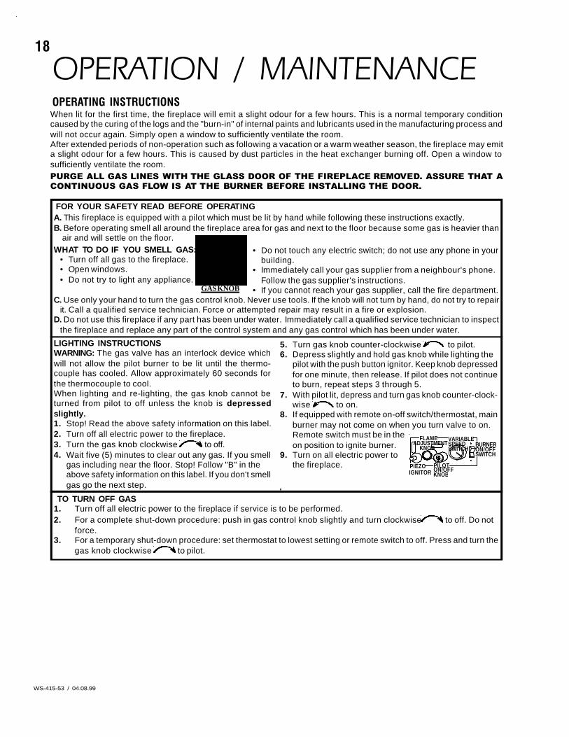
OPERATION / MAINTENANCEOPERATING INSTRUCTIONSWhen lit for the first time, the fireplace will emit a slight odour for a few hours. This is a normal temporary conditioncaused by the curing of the logs and the "burn-in" of internal paints and lubricants used in the manufacturing process andwill not occur again. Simply open a window to sufficiently ventilate the room.After extended periods of non-operation such as following a vacation or a warm weather season, the fireplace may emita slight odour for a few hours. This is caused by dust particles in the heat exchanger burning off. Open a window tosufficiently ventilate the room.PURGE ALL GAS LINES WITH THE GLASS DOOR OF THE FIREPLACE REMOVED. ASSURE THAT ACONTINUOUS GAS FLOW IS AT THE BURNER BEFORE INSTALLING THE DOOR.
A. This fireplace is equipped with a pilot which must be lit by hand while following these instructions exactly.B. Before operating smell all around the fireplace area for gas and next to the floor because some gas is heavier than
air and will settle on the floor.WHAT TO DO IF YOU SMELL GAS:
• Turn off all gas to the fireplace.• Open windows.• Do not try to light any appliance.
C. Use only your hand to turn the gas control knob. Never use tools. If the knob will not turn by hand, do not try to repairit. Call a qualified service technician. Force or attempted repair may result in a fire or explosion.
D. Do not use this fireplace if any part has been under water. Immediately call a qualified service technician to inspectthe fireplace and replace any part of the control system and any gas control which has been under water.
GAS KNOB
• Do not touch any electric switch; do not use any phone in yourbuilding.
• Immediately call your gas supplier from a neighbour's phone.Follow the gas supplier's instructions.
• If you cannot reach your gas supplier, call the fire department.
LIGHTING INSTRUCTIONSWARNING: The gas valve has an interlock device whichwill not allow the pilot burner to be lit until the thermo-couple has cooled. Allow approximately 60 seconds forthe thermocouple to cool.When lighting and re-lighting, the gas knob cannot beturned from pilot to off unless the knob is depressedslightly.1. Stop! Read the above safety information on this label.2. Turn off all electric power to the fireplace.3. Turn the gas knob clockwise to off.4. Wait five (5) minutes to clear out any gas. If you smell
gas including near the floor. Stop! Follow "B" in theabove safety information on this label. If you don't smellgas go the next step.
5. Turn gas knob counter-clockwise to pilot.6. Depress slightly and hold gas knob while lighting the
pilot with the push button ignitor. Keep knob depressedfor one minute, then release. If pilot does not continueto burn, repeat steps 3 through 5.
7. With pilot lit, depress and turn gas knob counter-clock-wise to on.
8. If equipped with remote on-off switch/thermostat, mainburner may not come on when you turn valve to on.Remote switch must be in theon position to ignite burner.
9. Turn on all electric power tothe fireplace.
I H SWITCHL O
LP
O F F N
TI O
O
PIEZO ON/OFFPILOTKNOBIGNITOR
SWITCHSPEEDVARIABLEFLAME
KNOBADJUSTMENT BURNER
ON/OFF
FOR YOUR SAFETY READ BEFORE OPERATING
TO TURN OFF GAS1. Turn off all electric power to the fireplace if service is to be performed.2. For a complete shut-down procedure: push in gas control knob slightly and turn clockwise to off. Do not
force.3. For a temporary shut-down procedure: set thermostat to lowest setting or remote switch to off. Press and turn the
gas knob clockwise to pilot.
19
WS-415-53 / 04.08.99
MAINTENANCE TURN OFF THE GAS AND ELECTRICAL POWER BEFORE SERVICING THE FIREPLACE.CAUTION: Label all wires prior to disconnection when servicing controls. Wiring errors can cause improper and danger-ous operation. Verify proper operation after servicing. This fireplace and its venting system should be inspected beforeuse and at least annually by a qualified service person. The fireplace area must be kept clear and free of combustiblematerials, gasoline or other flammable vapours and liquids. The flow of combustion and ventilation air must not beobstructed.
1. In order to properly clean the burner and pilot assembly, remove the logs to expose both assemblies.
2. Keep the control compartment, logs, burner, air shutter opening and the area surrounding the logs clean byvacuuming or brushing, at least once a year.
3. Check to see that all burner ports are burning. Clean out any of the ports which may not be burning or arenot burning properly. (right brick panel must be removed in order to facilitate burner removal, where appli-cable.)
4. Check to see that the pilot flame is large enough to engulf the thermocouple and thermopile and reachestoward the burner with the third jet.
5. Replace the cleaned logs.
6. Check to see that the main burner ignites completely on all openings when the gas knob for the burner isturned on. A 5 to 10 second total light-up period is satisfactory. If ignition takes longer, consult your Napoleondealer / distributor.
7. Check that the gasketing on the sides, top and bottom of the door is not broken or missing. Replace ifnecessary.
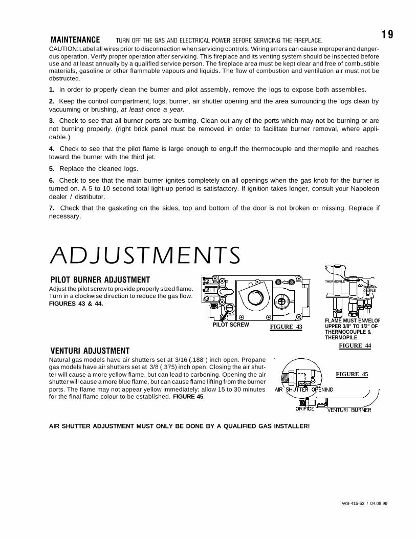
ADJUSTMENTSPILOT BURNER ADJUSTMENTAdjust the pilot screw to provide properly sized flame.Turn in a clockwise direction to reduce the gas flow.FIGURES 43 & 44.
VENTURI ADJUSTMENTNatural gas models have air shutters set at 3/16 (.188") inch open. Propanegas models have air shutters set at 3/8 (.375) inch open. Closing the air shut-ter will cause a more yellow flame, but can lead to carboning. Opening the airshutter will cause a more blue flame, but can cause flame lifting from the burnerports. The flame may not appear yellow immediately; allow 15 to 30 minutesfor the final flame colour to be established. FIGURE 45.
AIR SHUTTER ADJUSTMENT MUST ONLY BE DONE BY A QUALIFIED GAS INSTALLER!
FLAME MUST ENVELOPUPPER 3/8" TO 1/2" OFTHERMOCOUPLE & THERMOPILE
THERMO-COUPLE
THERMOPILE
FIGURE 44
P
I
PI
PILOT SCREW
LOT
N O
L
O
THI
LO
FF O
FIGURE 43
FIGURE 45
20
WS-415-53 / 04.08.99
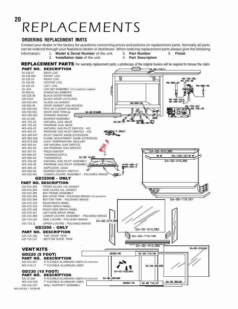
REPLACEMENTSORDERING REPLACEMENT PARTSContact your dealer or the factory for questions concerning prices and policies on replacement parts. Normally all partscan be ordered through your Napoleon dealer or distributor. When ordering replacement parts always give the followinginformation: 1. Model & Serial Number of the unit. 3. Part Number 5. Finish
2. Installation date of the unit. 4. Part Description
REPLACEMENT PARTS For warranty replacement parts, a photocopy of the original invoice will be required to honour the claim.PART NO. DESCRIPTIONGI-135.07 BACK LOGGI-135.052 FRONT LOGGI-135.15 RIGHT LOGGI-135.09 CENTER LOGGI-135.16 LEFT LOGGL-610 LOG SET ASSEMBLY C/W CHARCOAL EMBERS
GI-550.01 CHARCOAL EMBERSGD-225.36 BLACK DOOR FRAMEGD-321K BLACK DOOR c/w GLASSGD-010.454 GLASS c/w GASKETGD-562.09 DOOR GASKET (100 INCHES)GD-020.042 PKG OF 5 DOOR SCREWSGD-200.055 DOOR SIDE TRIM eaWS-430-001 CERAMIC MAGNETGD-10.352 BURNER ASSEMBLYWS-725-25 NATURAL GAS VALVEWS-725-26 PROPANE GAS VALVEWS-455-23 NATURAL GAS PILOT ORIFICE - #51WS-455-24 PROPANE GAS PILOT ORIFICE - #30WS-380-007 PILOT ON/OFF KNOB EXTENSIONWS-380-006 FLAME ADJUSTMENT KNOB EXTENSIONWS-573-008 HIGH TEMPERATURE SEALANTWS-455-04 #36 NATURAL GAS ORIFICEWS-455-03 #54 PROPANE GAS ORIFICEWS-357-01 PIEZO IGNITERWS-680-05 THERMOCOUPLEWS-680-04 THERMOPILEWS-100-38 NATURAL GAS PILOT ASSEMBLYWS-100-39 PROPANE GAS PILOT ASSEMBLYWS-385-33 NAPOLEON LOGOWS-660-05 BURNER ON/OFF SWITCHGD-010.391 LOWER LOUVRE ASSEMBLY - POLISHED BRASS
GD3200B - ONLYPART NO. DESCRIPTIONGD-010.383 FRONT GLASS c/w GASKETGD-010.384 SIDE GLASS c/w GASKETGD-010.385 BAY FRAME ASSEMBLYGD-010.395 BAY DOOR TRIM - POLISHED BRASS C/W MAGNETS
GD-010.389 BOTTOM TRIM - POLISHED BRASSGD-475.149 REAR BRICK PANELGD-475.153 FRONT BRICK PANELGD-475.148 RIGHT SIDE BRICK PANELGD-475.147 LEFT SIDE BRICK PANELGD-010.388 LOWER LOUVRE ASSEMBLY - POLISHED BRASSGD-715.145 SIDE LOUVRE - POLISHED BRASS
GD-715.11 UPPER LOUVRE - POLISHED BRASS
GD3200 - ONLYPART NO. DESCRIPTIONGD-715.136 TOP DOOR TRIMGD-715.137 BOTTOM DOOR TRIM
VENT KITSGD220 (5 FOOT)PART NO. DESCRIPTIONGD-010.397 4" FLEXIBLE ALUMINUM LINER C/W SPACERS
WS-410-17 7" FLEXIBLE ALUMINUM LINER
GD330 (10 FOOT)PART NO. DESCRIPTIONGS-10.300 4" FLEXIBLE ALUMINUM LINER C/W SPACERS
WS-410-018 7" FLEXIBLE ALUMINUM LINERGD-010.370 WALL SUPPORT ASSEMBLY
P
I
PILOT
N OIL
O
TH
LO
FF O
N
O
L
FF
T
IO
O
P
I
H
LO
22
WS-415-53 / 04.08.99
TROUBLE SHOOTING GUIDE
Carbon is being de-posited on glass,logs or combustionchamber surfaces. Flame is impinging on the
logs or combustion cham-ber.
- check that the logs are correctly positioned.- open air shutter to increase the primary air.- check the input rate: check the manifold pressure and orifice sizeas specified by the rating plate values.- check that the door gasketing is not broken or missing and that theseal is tight.- check that both 4" and 7" vent liners are free of holes and wellsealed at all joints.- check that minimum rise per foor has been adhered to for anyhorizontal venting.
Air shutter has becomeblocked
- ensure air shutter opening is free of lint or other obstructions.
White / grey filmforms.
Sulphur from fuel is beingdeposited on glass, logs orcombustion chamber sur-faces.
- clean the glass with a gas fireplace glass cleaner. DO NOT CLEANGLASS WHEN HOT.If deposits are not cleaned off regularly, the glass may become per-manently marked.
Exhaust fumessmelled in room,headaches.
Fireplace is spilling. - check door seal and relief flap seal.- check for chimney blockage- check that chimney is installed to building code.- room is in negative pressure; increase fresh air supply.
Pilot goes out whenthe gas knob is re-leased.The gas valve hasan interlock de-vice which will notallow the pilotburner to be lit un-til the thermo-couple hascooled. Allow ap-proximately 60seconds for thethermocouple tocool.
System is not correctlypurged.
- purge the gas line.
Out of propane gas. - fill the tank.
Pi lot f lame is not largeenough
- turn up the pilot flame.
- gently twist the pilot head to improve the flame pattern around thethermocouple.
Pilot flame is not engulfingthe thermocouple.
Thermocouple short ing /faulty.
- loosen and tighten thermocouple.- clean thermocouple and valve connection.- replace thermocouple.- replace valve.
Faulty valve. - replace.
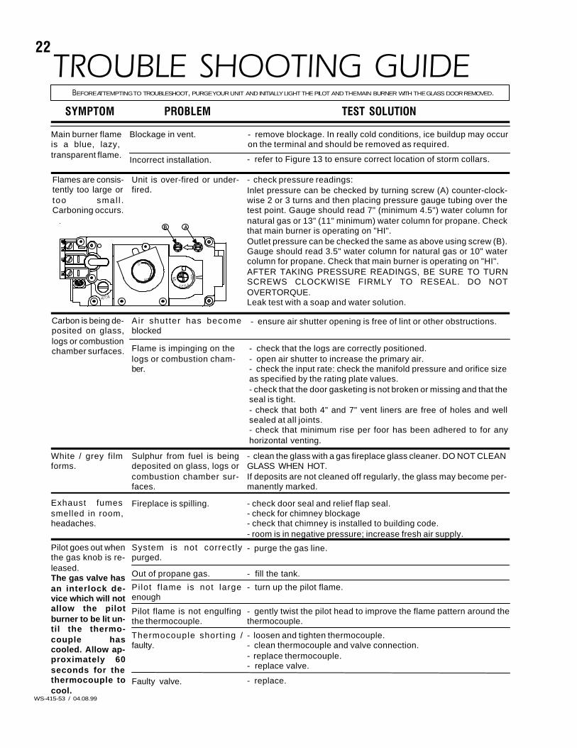
BEFORE ATTEMPTING TO TROUBLESHOOT, PURGE YOUR UNIT AND INITIALLY LIGHT THE PILOT AND THE MAIN BURNER WITH THE GLASS DOOR REMOVED.
TEST SOLUTIONSYMPTOM PROBLEM
Main burner flameis a blue, lazy,transparent flame.
Blockage in vent. - remove blockage. In really cold conditions, ice buildup may occuron the terminal and should be removed as required.
Incorrect installation. - refer to Figure 13 to ensure correct location of storm collars.
Flames are consis-tently too large ortoo smal l .Carboning occurs.
- check pressure readings:Inlet pressure can be checked by turning screw (A) counter-clock-wise 2 or 3 turns and then placing pressure gauge tubing over thetest point. Gauge should read 7" (minimum 4.5") water column fornatural gas or 13" (11" minimum) water column for propane. Checkthat main burner is operating on "HI".Outlet pressure can be checked the same as above using screw (B).Gauge should read 3.5" water column for natural gas or 10" watercolumn for propane. Check that main burner is operating on "HI".AFTER TAKING PRESSURE READINGS, BE SURE TO TURNSCREWS CLOCKWISE FIRMLY TO RESEAL. DO NOTOVERTORQUE.Leak test with a soap and water solution.
Unit is over-fired or under-fired.
P
I
AB
PILOT
N O
L
O
THI
LO
FF O
23
WS-415-53 / 04.08.99
TEST SOLUTIONPROBLEMSYMPTOM
Remote wall switchis in "OFF" position;main burner comeson when gas knobis turned to "ON"position.
Wall switch is mounted up-side down
- reverse.
Faulty valve. - replace.
- replace.Remote wal l switch isgrounding.
- check for ground (short); repair ground or replace wire.Remote wall switch wire isgrounding.
Main burner goesout; pilot goes out.
Refer to "MAIN BURNER GOES OUT; PILOT STAYS ON"
Vent is blocked
Vent is re-circulating
- check for vent blockage.
- check joint seals and installation.
4" flexible vent has becomedisconnected from fireplace.
- re-attach to fireplace.
Main burner goesout; pilot stays on.
Pi lot f lame is not largeenough or not engulfing thethermopile
- turn up pilot flame.- replace pilot assembly.
Thermopile shorting - clean thermopile connection to the valve. Reconnect.- replace thermopile / valve.
Remote wall switch wire istoo long; too much resis-tance in the system.
- shorten wire to correct length or wire gauge.
Faulty thermostat or switch. - replace.
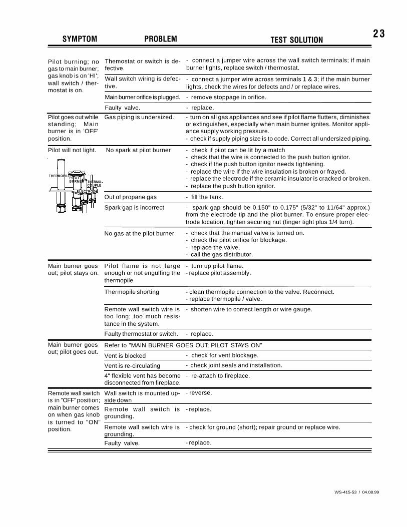
Pilot will not light. - check if pilot can be lit by a match- check that the wire is connected to the push button ignitor.- check if the push button ignitor needs tightening.- replace the wire if the wire insulation is broken or frayed.- replace the electrode if the ceramic insulator is cracked or broken.- replace the push button ignitor.
No spark at pilot burner
- fill the tank.Out of propane gas
Spark gap is incorrect - spark gap should be 0.150" to 0.175" (5/32" to 11/64" approx.)from the electrode tip and the pilot burner. To ensure proper elec-trode location, tighten securing nut (finger tight plus 1/4 turn).
No gas at the pilot burner - check that the manual valve is turned on.- check the pilot orifice for blockage.- replace the valve.- call the gas distributor.
PILOTTHERMOPILE
BURNER
ELECTRODE
THERMO-COUPLE
Pilot goes out whilestanding; Mainburner is in 'OFF'position.
Gas piping is undersized. - turn on all gas appliances and see if pilot flame flutters, diminishesor extinguishes, especially when main burner ignites. Monitor appli-ance supply working pressure.- check if supply piping size is to code. Correct all undersized piping.
Pilot burning; nogas to main burner;gas knob is on 'HI';wall switch / ther-mostat is on.
Themostat or switch is de-fective.
- connect a jumper wire across the wall switch terminals; if mainburner lights, replace switch / thermostat.
Wall switch wiring is defec-tive.
- connect a jumper wire across terminals 1 & 3; if the main burnerlights, check the wires for defects and / or replace wires.
Main burner orifice is plugged. - remove stoppage in orifice.
Faulty valve. - replace.

24
WS-415-53 / 04.08.99
NOTES: