BioMart Federated Database Architecture Arek Kasprzyk EBI 9 June 2005.
Upload
nguyencongCategory
view
217download
3
Test Cases for LISA 7.7
©2012 LISA-Finite Element Technologies, Sonnenhof Holdings (Canada) http://lisa-fet.com
1
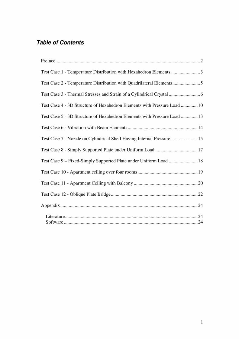
Table of Contents
Preface........................................................................................................................2
Test Case 1 - Temperature Distribution with Hexahedron Elements ........................3
Test Case 2 - Temperature Distribution with Quadrilateral Elements.......................5
Test Case 3 - Thermal Stresses and Strain of a Cylindrical Crystal ..........................6
Test Case 4 - 3D Structure of Hexahedron Elements with Pressure Load ..............10
Test Case 5 - 3D Structure of Hexahedron Elements with Pressure Load ..............13
Test Case 6 - Vibration with Beam Elements ..........................................................14
Test Case 7 - Nozzle on Cylindrical Shell Having Internal Pressure ......................15
Test Case 8 - Simply Supported Plate under Uniform Load ...................................17
Test Case 9 – Fixed-Simply Supported Plate under Uniform Load ........................18
Test Case 10 - Apartment ceiling over four rooms..................................................19
Test Case 11 - Apartment Ceiling with Balcony .....................................................20
Test Case 12 - Oblique Plate Bridge........................................................................22
Appendix..................................................................................................................24
Literature..............................................................................................................24 Software ...............................................................................................................24
2
Preface
For users who trust the ANSYS FEA software from Swanson Analysis Systems Inc., test cases have been performed to illustrate that LISA's analysis results are very much at par with ANSYS analysis results. A few test cases compare LISA analysis results with those obtained from the BEM (Boundary Element Method) and Analytical results from scientific literature. Differences in the results can be attributed to element formulations and the mesh layouts especially in areas of peak stresses. Usually peak stresses are not included in stress classification procedures for static analysis. Unexpected high or low peak stresses may occur in finite element models with singularities. Singularities can arise in reentrant corners, nozzle/shell junctions and at point or line constraints. All the LISA test cases are provided in the native LISA (*.liml) file format.

3
Test Case 1 - Temperature Distribution with Hexahedron Elements
This analysis obtains the temperature distribution in a cylindrical crystal with isotropic material behavior. Both ends of the crystal are insulated with heat transfer occurring only at the perimeter. The perimeter of the cylinder is maintained at a fixed temperature of 0°C. The ANSYS model has it's perimeter at the fixed temperature (Dirichlet boundary condition) 0°C. In the LISA model, the fixed temperature boundary condition (Dirichlet boundary condition) has been simulated with a Cauchy boundary condition, a large heat transfer coefficient and an ambient temperature of 0°C. As the model is symmetrical in two directions only a quarter of the cylinder has been idealized with Finite Elements. In the square region, internal heat sources have been considered. The model has been idealized with hexahedron elements.

4
Fig.4: Temperature distribution computed with LISA

5
Test Case 2 - Temperature Distribution with Quadrilateral Elements
The same model from Test Case 1 has been idealized with 4 node quadrilateral shell elements. The LISA computation results are almost exact to the results of the hexahedron element model.
Fig.5: Temperature distribution computed with quadrilateral elements

6
Test Case 3 - Thermal Stresses and Strain of a Cylindrical Crystal
The model described in Test Case 1 is now analyzed for stresses and displacements due to the temperature distribution computed above. A quarter of the cylinder has been idealized with hexahedron elements. The material properties are as shown in fig.1, and isotropic material behavior is assumed. LISA stress and displacement results will be compared to ANSYS results.
Fig.6: Restraint displacements of cylinder model
While the mesh topology of the earlier test cases for LISA and ANSYS has been retained, the LISA mesh can be observed to be a little bit coarser than the ANSYS model.
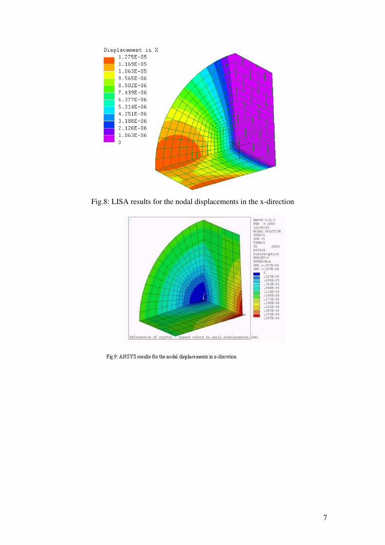
7
Fig.8: LISA results for the nodal displacements in the x-direction
8
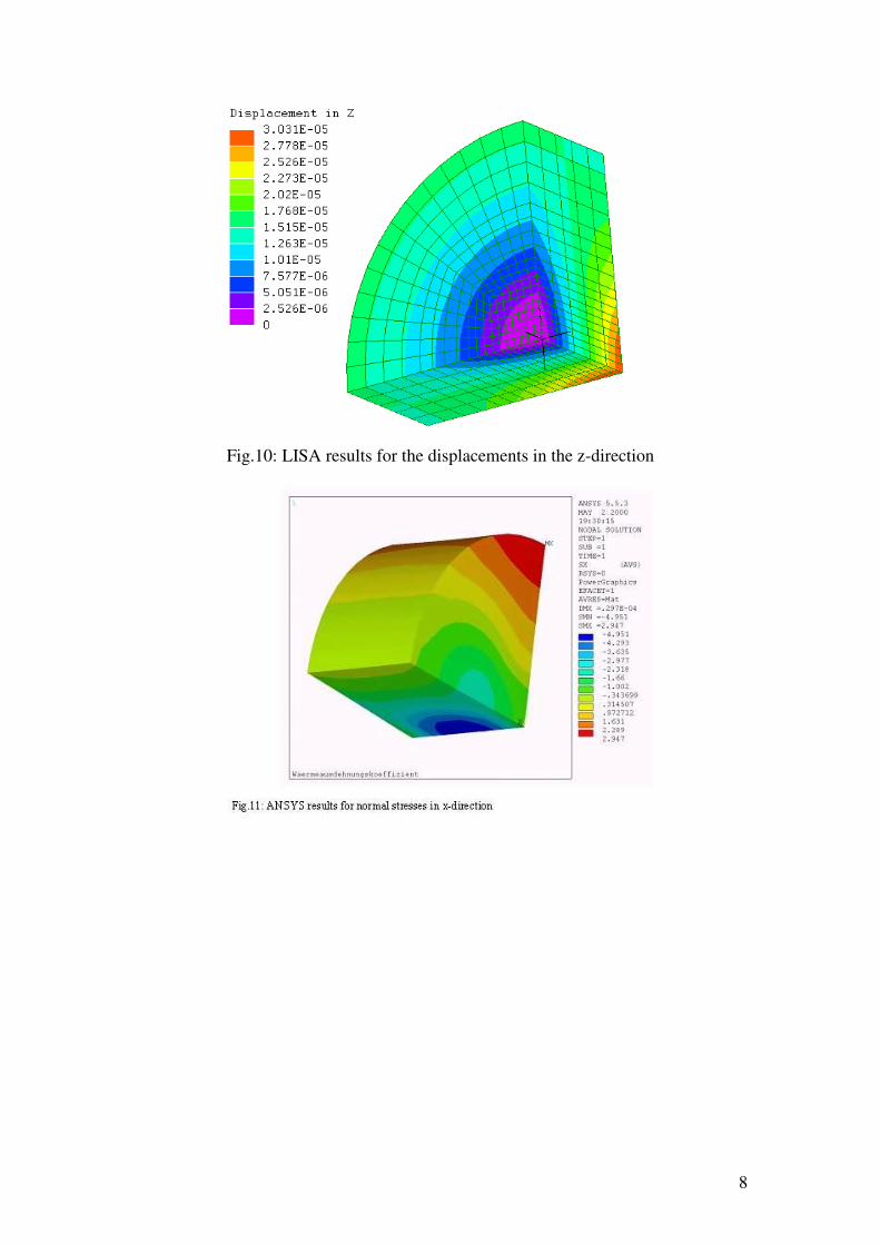
Fig.10: LISA results for the displacements in the z-direction

9
Fig.12: LISA results for normal stresses in the x-direction
Fig.14: LISA results for normal stresses in the z-direction

10
Test Case 4 - 3D Structure of Hexahedron Elements with Pressure Load The LISA computation results of a three-dimensional structure subjected to internal pressure will be compared to the computation results from an ANSYS analysis.
11
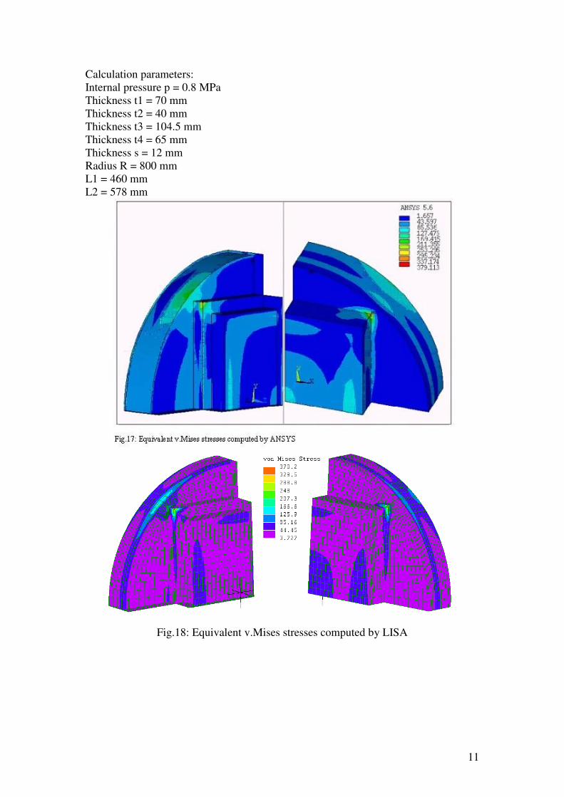
Calculation parameters: Internal pressure p = 0.8 MPa Thickness t1 = 70 mm Thickness t2 = 40 mm Thickness t3 = 104.5 mm Thickness t4 = 65 mm Thickness s = 12 mm Radius R = 800 mm L1 = 460 mm L2 = 578 mm
Fig.18: Equivalent v.Mises stresses computed by LISA

12
Fig.20: Equivalent v.Mises stresses at the upper and under side of the cover computed
by LISA

13
Test Case 5 - 3D Structure of Hexahedron Elements with Pressure Load The LISA computation results of a three-dimensional structure subjected to internal pressure will be compared with the computation results of an ANSYS Analysis. The structure of this test case is very similar to the structure of test case 4, except that the thicknesses t3 and t4 are zero and therefore not considered in the following model. Calculation parameters: Internal pressure p = 2.8 MPa Thickness t1 = 170 mm Thickness t2 = 70 mm Thickness s = 20 mm Radius R = 685 mm L1 = 357.5 mm L2 = 550 mm
Fig.21: Equivalent v.Mises stresses computed by ANSYS
Fig.22: Equivalent v.Mises stresses computed by LISA

14
Test Case 6 - Vibration with Beam Elements
This test case is of the vibration of a multiple supported 2D beam. The beam length is 4446 mm. The space between each support is 494 mm. The moment of inertia of the beam is 2319.668 mm4.
Fig.23: Mesh and boundary conditions of the LISA model
Fig.24: First transverse mode shape computed by ANSYS
Fig.25: First transverse mode shape computed by LISA
Frequencies computed by LISA: 1st transverse mode (fig. 25): 97.77 Hz 2nd transverse mode: 107.09 Hz 3rd transverse mode: 121.06 Hz

15
Test Case 7 - Nozzle on Cylindrical Shell Having Internal Pressure
LISA’s template for nozzles on cylindrical shells has been used to model the structure having an internal pressure. The LISA results are compared to the results from the FE Pipe program. FE Pipe is a computer program for special vessel components, and uses the Finite Element Method. For the LISA model, 8-node thick shell elements with selective integration have been used. The local stresses at the vessel/nozzle junction as computed with FE Pipe and LISA are compared. Dimensions Branch pipe outside diameter (mm) Branch wall thickness (mm) Internal pressure (N/mm2) Modulus of elasticity (MPa) Poissons ratio Header outside diameter (mm) Header wall thickness (mm)
1219.2 18.4 0.4 199950 0.3 2100 13.4
FE Pipe results compared to LISA Max. v.Mises stress Max. v.Mises membrane stresses
FE Pipe 184 MPa 125 MPa
LISA 169 MPa 126 MPa
Difference 8% 1%
Fig.26: von Mises stresses computed by FE Pipe. The values at the vessel/nozzle
junction are increased by a weld stress concentration factor of 1.35.

16
Fig.27: von Mises stresses computed by LISA
Fig.28: von Mises membrane stresses computed by FE Pipe. The values at the
vessel/nozzle junction are increased by a weld stress concentration factor of 1.35.
Fig.29: von Mises membrane stresses computed by LISA

17
Test Case 8 - Simply Supported Plate under Uniform Load
A simply supported plate according to Literature [4] has been idealized using quadrilateral 4 node shell elements to model 1 quarter of the pate.
Fig.30: Plate parameters and constraints according to [4]
Fig.31: Transverse deformation of the plate in the LISA model. Units are mm
Solution method 8 boundary elements 16 boundary elements LISA Czerny
Displacement in z [mm] 0.6550 0.6573 0.6598 0.6575
Max. bending moment 3.3031 3.3122 3.3146 3.3088
18
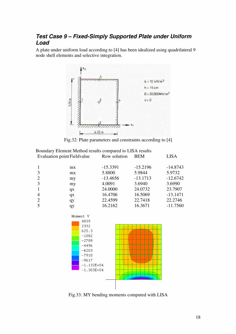
Test Case 9 – Fixed-Simply Supported Plate under Uniform Load
A plate under uniform load according to [4] has been idealized using quadrilateral 9 node shell elements and selective integration.
Fig.32: Plate parameters and constraints according to [4]
Boundary Element Method results compared to LISA results Evaluation point 1 3 2 3 1 4 2 5
Fieldvalue mx mx my my qx qx qy qy
Row solution -15.3391 5.8800 -13.4656 4.0091 24.0000 16.4706 22.4599 16.2162
BEM -15.2196 5.9844 -13.1713 3.6940 24.0732 16.5069 22.7418 16.3671
LISA -14.8743 5.9732 -12.6742 3.6990 23.7907 -13.1471 22.2746 -11.7560
Fig.33: MY bending moments computed with LISA

19
Test Case 10 - Apartment ceiling over four rooms
A ceiling of an apartment according to [4] has been idealized using quadrilateral 9 node shell elements and selective integration. The loading is uniform loading and loading due to gravity.
Fig.34: Ceiling, loads and evaluation points according to [4]
Boundary element results at evaluation points compared to LISA results. Evaluation point 1 2 3 4 5 6 6 7 7 8 8 9 9
Field value M2 M1 M2 M2 M1 M1 M2 M1 M2 M1 M2 M1 M2
BEM -28.255 -22.945 -17.474 -23.233 -16.642 7.95 3.27 7.58 10.18 5.65 5.71 2.75 7.27
Cross/Brunner -28.64 -23.64 -17.99 -24.71 -17.26 8.29 5.05 7.94 10.41 5.51 5.51 4.51 7.60
Marcus -25.00 -21.04 -15.13 -24.91 -14.92
LISA -25.991 -21.842 -16.027 -22.243 -15.245 8.161 5.161 8.124 10.874 5.736 5.804 4.613 7.473
Fig.35: MX bending moments computed with LISA

20
Test Case 11 - Apartment Ceiling with Balcony
A ceiling of an apartment with balcony according to [4] has been idealized using quadrilateral 9 node shell elements and selective integration. The load due to gravity has been considered in the analysis.
Fig.36: Ceiling with balcony according to [4]
Fig.37: MY bending moments computed with LISA

21
Fig.38: MY moments at x1=1 computed with LISA (lower) and BEM [4] (upper)
Fig.39: MY moments at x1=5 computed with LISA (lower) and BEM [4] (upper)

22
Test Case 12 - Oblique Plate Bridge
An oblique plate bridge according to [4] has been idealized with quadrilateral 9 node shell elements and selective integration. The load due to gravity has been considered in the analysis.
Fig.40: Boundary conditions and parameters of the plate bridge according to [4]
Fig.41: Results for the bending moments with BEM and different types of finite
elements according to [4]
Fig.42: LISA results for the M1 bending moments

23
Fig.43: LISA results for the M2 bending moments

24
Appendix
Literature
[1] Welding Research Council 107 (WRC 107) K.R. Wichman, A.G. Hopper and J.L.Mershon 1979. [2] Praxisorientierte Aufbereitung des Ermüdungsfestigkeitsnachweises für Komponenten der Druckbehälter- und Kraftwerkstechnik, Jürgen Rudolph und Eckard Weiss, Chemie Ingenieur Technik (69) S. 68-76 VCH Verlagsgesellschaft mbH, D-69469 Weinheim, 1997, 0009 286X/970102-0068 $10.00+25/0 [3] Festigkeitsberechnungen im Dampfkessel-, Behälter- und Rohrleitungsbau / S. Schwaigerer / 4. überarbeitete Auflage ISBN 3-540-12255-9 4.Aufl. Springer-Verlag Berlin Heidelberg New York Tokyo ISBN 0-387-12255-9 4th ed. Springer-Verlag New York Heidelberg Berlin Tokyo [4] Friedel Hartmann, Methode der Randelemente, Boundary Elements in der Mechanik auf dem PC, Springer-Verlag Berlin Heidelberg New York London Paris Tokyo 1987 ISBN 3-540-17336-6 ISBN 0-387-17336-6
Software
ANSYS is a registered trademark of Swanson Analysis Systems. FE Pipe is a A.Boaz/Paulin Product


![Dr Eng. Jan Pająk Web pages of Jan Pająk - telekinesisthe knowledge on telekinesis that so-far was unknown to people, is a slightly older scientific monograph marked [8], which carries](https://static.fdocuments.us/doc/165x107/6109d4fb09fe045c46573a46/dr-eng-jan-pajk-web-pages-of-jan-pajk-telekinesis-the-knowledge-on-telekinesis.jpg)