LIQUIP DRYBREAK COUPLER API700 Series...
22
THIS IS CONFIDENTIAL INFORMATION. THIS DRAWING AND DESIGN IS THE PROPERTY OF LIQUIP INTERNATIONAL PTY LIMITED. IT MUST NOT BE COPIED OR REPRODUCED IN ANY WAY WHATSOEVER AND/OR PASSED ON TO ANY THIRD PARTY WITHOUT WRITTEN AUTHORITY. LIQUIP INTERNATIONAL PTY LIMITED - ENGINEERING DEPARTMENT - 13 HUME RD SMITHFIELD SYDNEY NSW AUSTRALIA 2164 PH: +61 2 9725 9000 FAX: +61 2 9609 4739 EMAIL: [email protected] M:\Product-Info\API7xx\6-Service-Maintenance\API7XX_S&M_OVERHAUL_PROCEDURE_API00608.doc Issue: C 16/7/08 Page 1 LIQUIP DRYBREAK COUPLER API700 Series OVERHAUL PROCEDURE API LOADING COUPLER TO API RP1004 July 2008 Issue: C
Transcript of LIQUIP DRYBREAK COUPLER API700 Series...

THIS IS CONFIDENTIAL INFORMATION. THIS DRAWING AND DESIGN IS THE PROPERTY OF LIQUIP INTERNATIONAL PTY LIMITED.
IT MUST NOT BE COPIED OR REPRODUCED IN ANY WAY WHATSOEVER AND/OR PASSED ON TO ANY THIRD PARTY WITHOUT WRITTEN AUTHORITY.
LIQUIP INTERNATIONAL PTY LIMITED - ENGINEERING DEPARTMENT - 13 HUME RD SMITHFIELD SYDNEY NSW AUSTRALIA 2164 PH: +61 2 9725 9000 FAX: +61 2 9609 4739 EMAIL: [email protected]
M:\Product-Info\API7xx\6-Service-Maintenance\API7XX_S&M_OVERHAUL_PROCEDURE_API00608.doc Issue: C 16/7/08 Page 1
LIQUIP DRYBREAK COUPLER
API700 Series
OVERHAUL PROCEDURE
API LOADING COUPLER TO API RP1004
July 2008 Issue: C
THIS IS CONFIDENTIAL INFORMATION. THIS DRAWING AND DESIGN IS THE PROPERTY OF LIQUIP INTERNATIONAL PTY LIMITED.
IT MUST NOT BE COPIED OR REPRODUCED IN ANY WAY WHATSOEVER AND/OR PASSED ON TO ANY THIRD PARTY WITHOUT WRITTEN AUTHORITY.
LIQUIP INTERNATIONAL PTY LIMITED - ENGINEERING DEPARTMENT - 13 HUME RD SMITHFIELD SYDNEY NSW AUSTRALIA 2164 PH: +61 2 9725 9000 FAX: +61 2 9609 4739 EMAIL: [email protected]
M:\Product-Info\API7xx\6-Service-Maintenance\API7XX_S&M_OVERHAUL_PROCEDURE_API00608.doc Issue: C 16/7/08 Page 2
CONTENTS
1. DATA SHEET PAGE 3 2. SPARE PARTS LIST PAGE 5 3. INTEGRITY TESTING STANDARD PAGE 7 4. TROUBLE SHOOTING PAGE 8 5. REPLACEMENT OF TEE SEAL PAGE 9 6. DIS-ASSEMBLY PROCEDURE (PARTIAL) PAGE 10 7. RE-ASSEMBLY PROCEDURE (PARTIAL) PAGE 13 8. COMPLETE DIS-ASSEMBLY PROCEDURE PAGE 15 9. COMPLETE RE-ASSEMBLY PROCEDURE PAGE 18 10. TESTING PAGE 21 11. PERIODIC CHECKS PAGE 22
THIS IS CONFIDENTIAL INFORMATION. THIS DRAWING AND DESIGN IS THE PROPERTY OF LIQUIP INTERNATIONAL PTY LIMITED.
IT MUST NOT BE COPIED OR REPRODUCED IN ANY WAY WHATSOEVER AND/OR PASSED ON TO ANY THIRD PARTY WITHOUT WRITTEN AUTHORITY.
LIQUIP INTERNATIONAL PTY LIMITED - ENGINEERING DEPARTMENT - 13 HUME RD SMITHFIELD SYDNEY NSW AUSTRALIA 2164 PH: +61 2 9725 9000 FAX: +61 2 9609 4739 EMAIL: [email protected]
M:\Product-Info\API7xx\6-Service-Maintenance\API7XX_S&M_OVERHAUL_PROCEDURE_API00608.doc Issue: C 16/7/08 Page 3
API71X SERIES DRY BREAK COUPLERS P7486
DATA SHEET PART No: API710 / VG
API712 / VG TITLE: API bottom loading dry-break coupler with automatic latching.
OPERATION: Automatic push and latch operation with dry-break coupling and safety lock. Used for loading tank trucks.
FEATURES: API71x series couplers are a major advance on previous designs, addressing well-known issues: - • Advanced latching mechanism geometry for security and minimal wear. • Cast stainless steel collar for long operating life and to minimise operator damage. • Latch spindles are now precision machined and centred, not cast integrally. • Optional handle sizes, 150mm (6”) or 200mm (7.9”) swing, incorporates a ball-end for
improved ergonomics and a carry-loop to ease the handling during parking.
DISMANTLE: Easiest of all couplers to dismantle. Removal of one “R” clip enables the shaft assembly and main poppet to be withdrawn.
ADJUSTMENT: None Required.
TECHNICAL DATA:
API710 has 150mm long handle, API712 has 200mm long handle API710VG & API712VG have Viton GFLT seals – recommended for ethanol blends. Separate spindle on latch, with coil spring actuation, for improved smoothness and consistency. Chamfered bore and moulded seal in nose for ease of coupling and drip-free operation. Pressure-to-leak 2500kPa (363 PSI) uncoupled Testing pressure 1500kPa (218 PSI) uncoupled. Operating pressure 1000kPa (145 PSI) Max coupling/uncoupling pressure 550kPa (80 PSI). Max coupled pressure 2000kPa (290 PSI). Operating temperature: -20° to +80°C (-4° to +176°F) for Viton B70 seals. -40° to +60°C (-40° to +140°F) for Viton GFLT seals. Aluminium bodies, hard anodised for wear resistance. Cast stainless steel collar High tensile steel shaft. Super-tough die-cast and heat-treated stainless steel locking latches. Viton B70 seals throughout. Viton GFLT available on request. Replaceable bearings at both ends of shaft for support. Wave washer as main seal. Weight: 9.2kg (20.3lb)
MOUNTING: By Industry Standard 100mm (4”) TTMA flange. 8 holes Ø11mm on 149mm PCD, 168 outside diameter (Ø7/16” on 5.8” PCD, 6.6” OD) Use spring washers when mounting coupler.
ASSOCIATED EQUIPMENT:
Liquip ‘Velvet Touch’ Loading Arms.
Overall dimensions shown on the drawing overleaf.

THIS IS CONFIDENTIAL INFORMATION. THIS DRAWING AND DESIGN IS THE PROPERTY OF LIQUIP INTERNATIONAL PTY LIMITED.
IT MUST NOT BE COPIED OR REPRODUCED IN ANY WAY WHATSOEVER AND/OR PASSED ON TO ANY THIRD PARTY WITHOUT WRITTEN AUTHORITY.
LIQUIP INTERNATIONAL PTY LIMITED - ENGINEERING DEPARTMENT - 13 HUME RD SMITHFIELD SYDNEY NSW AUSTRALIA 2164 PH: +61 2 9725 9000 FAX: +61 2 9609 4739 EMAIL: [email protected]
M:\Product-Info\API7xx\6-Service-Maintenance\API7XX_S&M_OVERHAUL_PROCEDURE_API00608.doc Issue: C 16/7/08 Page 4

THIS IS CONFIDENTIAL INFORMATION. THIS DRAWING AND DESIGN IS THE PROPERTY OF LIQUIP INTERNATIONAL PTY LIMITED.
IT MUST NOT BE COPIED OR REPRODUCED IN ANY WAY WHATSOEVER AND/OR PASSED ON TO ANY THIRD PARTY WITHOUT WRITTEN AUTHORITY.
LIQUIP INTERNATIONAL PTY LIMITED - ENGINEERING DEPARTMENT - 13 HUME RD SMITHFIELD SYDNEY NSW AUSTRALIA 2164 PH: +61 2 9725 9000 FAX: +61 2 9609 4739 EMAIL: [email protected]
M:\Product-Info\API7xx\6-Service-Maintenance\API7XX_S&M_OVERHAUL_PROCEDURE_API00608.doc Issue: C 16/7/08 Page 5

THIS IS CONFIDENTIAL INFORMATION. THIS DRAWING AND DESIGN IS THE PROPERTY OF LIQUIP INTERNATIONAL PTY LIMITED.
IT MUST NOT BE COPIED OR REPRODUCED IN ANY WAY WHATSOEVER AND/OR PASSED ON TO ANY THIRD PARTY WITHOUT WRITTEN AUTHORITY.
LIQUIP INTERNATIONAL PTY LIMITED - ENGINEERING DEPARTMENT - 13 HUME RD SMITHFIELD SYDNEY NSW AUSTRALIA 2164 PH: +61 2 9725 9000 FAX: +61 2 9609 4739 EMAIL: [email protected]
M:\Product-Info\API7xx\6-Service-Maintenance\API7XX_S&M_OVERHAUL_PROCEDURE_API00608.doc Issue: C 16/7/08 Page 6

THIS IS CONFIDENTIAL INFORMATION. THIS DRAWING AND DESIGN IS THE PROPERTY OF LIQUIP INTERNATIONAL PTY LIMITED.
IT MUST NOT BE COPIED OR REPRODUCED IN ANY WAY WHATSOEVER AND/OR PASSED ON TO ANY THIRD PARTY WITHOUT WRITTEN AUTHORITY.
LIQUIP INTERNATIONAL PTY LIMITED - ENGINEERING DEPARTMENT - 13 HUME RD SMITHFIELD SYDNEY NSW AUSTRALIA 2164 PH: +61 2 9725 9000 FAX: +61 2 9609 4739 EMAIL: [email protected]
M:\Product-Info\API7xx\6-Service-Maintenance\API7XX_S&M_OVERHAUL_PROCEDURE_API00608.doc Issue: C 16/7/08 Page 7
3. INTEGRITY TESTING STANDARD
This Standard, Document Number API00708.doc details routine tests and checks which can be applied to API couplers in service to determine if they require overhaul. Available from Liquip website or on request from Liquip head office in Sydney.

THIS IS CONFIDENTIAL INFORMATION. THIS DRAWING AND DESIGN IS THE PROPERTY OF LIQUIP INTERNATIONAL PTY LIMITED.
IT MUST NOT BE COPIED OR REPRODUCED IN ANY WAY WHATSOEVER AND/OR PASSED ON TO ANY THIRD PARTY WITHOUT WRITTEN AUTHORITY.
LIQUIP INTERNATIONAL PTY LIMITED - ENGINEERING DEPARTMENT - 13 HUME RD SMITHFIELD SYDNEY NSW AUSTRALIA 2164 PH: +61 2 9725 9000 FAX: +61 2 9609 4739 EMAIL: [email protected]
M:\Product-Info\API7xx\6-Service-Maintenance\API7XX_S&M_OVERHAUL_PROCEDURE_API00608.doc Issue: C 16/7/08 Page 8
4. TROUBLE SHOOTING LEAKS WHEN COUPLED WITH API450 ADAPTOR DURING LOADING This indicates the coupler face seal may be damaged or worn. Check visually on disconnection from the truck valve. Also check the API adaptor (truck valve) seal face for damage or wear. If replacement of the coupler tee seal is required this can be carried out with out taking the coupler valve out of service. Refer to section 5 LEAKS AROUND OPERATING SHAFT Leaks between the operating shaft and the bush are caused by worn or damaged o-rings on the operating shaft. Refer to section 5 for replacement of o-rings. LEAKS AROUND PISTON POPPET Leaks around the piston poppet are caused by worn or damaged o-rings in the adaptor ring. Refer to section 5 for replacement of o-rings. LEAKS AROUND ACETAL BUSH If a leak is suspected from between the Acetal bush and the body return the complete API7XX coupler to Liquip for removal and replacement of the Acetal bush. Inserting the Acetal bush requires use of a special tool. SPARE PARTS
Part Number Description Quantity 0235VB O-ring for shaft 2
0235EPDM O-ring for shaft EPDM 2 0235VG O-ring for shaft Viton GFLT 2 4602VB Product seal 1
4602EPDM Product seal EPDM 1 4602VG Product seal Viton GFLT 1 0203VB O-ring for inside & outside of poppet adaptor ring 2
0203EPDM O-ring for inside & outside of poppet adaptor ring EPDM 2 0203VG O-ring for inside & outside of poppet adaptor ring Viton GFLT 2
THIS IS CONFIDENTIAL INFORMATION. THIS DRAWING AND DESIGN IS THE PROPERTY OF LIQUIP INTERNATIONAL PTY LIMITED.
IT MUST NOT BE COPIED OR REPRODUCED IN ANY WAY WHATSOEVER AND/OR PASSED ON TO ANY THIRD PARTY WITHOUT WRITTEN AUTHORITY.
LIQUIP INTERNATIONAL PTY LIMITED - ENGINEERING DEPARTMENT - 13 HUME RD SMITHFIELD SYDNEY NSW AUSTRALIA 2164 PH: +61 2 9725 9000 FAX: +61 2 9609 4739 EMAIL: [email protected]
M:\Product-Info\API7xx\6-Service-Maintenance\API7XX_S&M_OVERHAUL_PROCEDURE_API0060
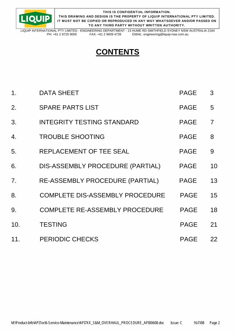
5. REPLACEMENT OF TEE SEAL (FACE SEAL) The photos below show the tee seal fitted to a closed valve. With a suitable tool, i.e. a smooth flat tool with no sharp edges, pry under the inside of the tee seal until you reach the bottom of the tee seal groove. Lever the tee seal gently up until you can pull the seal out with your fingers. Clean groove and poppet and replace seal ensuring you push the seal fully home to the bottom of the groove.
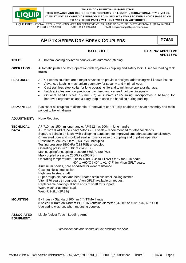
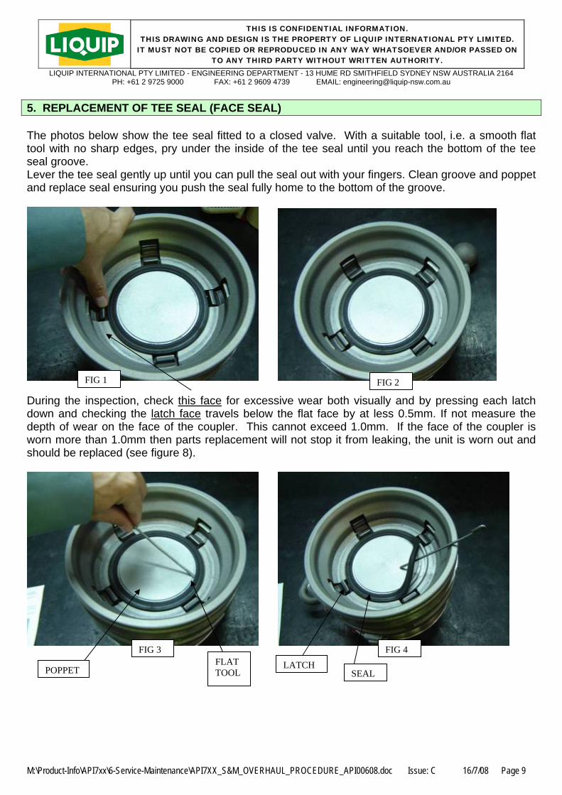
FIG 1 During the inspection, check this face for excessive wear both visudown and checking the latch face travels below the flat face by at depth of wear on the face of the coupler. This cannot exceed 1.0mworn more than 1.0mm then parts replacement will not stop it from should be replaced (see figure 8).
FLAT TOOL
T
FIG 2
ally and by pressing each latch less 0.5mm. If not measure the m. If the face of the coupler is
leaking, the unit is worn out and
FIG 38.
FIG 4
POPPE
LATCH SEALdoc Issue: C 16/7/08 Page 9

THIS IS CONFIDENTIAL INFORMATION. THIS DRAWING AND DESIGN IS THE PROPERTY OF LIQUIP INTERNATIONAL PTY LIMITED.
IT MUST NOT BE COPIED OR REPRODUCED IN ANY WAY WHATSOEVER AND/OR PASSED ON TO ANY THIRD PARTY WITHOUT WRITTEN AUTHORITY.
LIQUIP INTERNATIONAL PTY LIMITED - ENGINEERING DEPARTMENT - 13 HUME RD SMITHFIELD SYDNEY NSW AUSTRALIA 2164 PH: +61 2 9725 9000 FAX: +61 2 9609 4739 EMAIL: [email protected]
M:\Product-Info\API7xx\6-Service-Maintenance\API7XX_S&M_OVERHAUL_PROCEDURE_API00608.doc Issue: C 16/7/08 Page 10
6. DIS-ASSEMBLY FOR POPPET SEAL REPLACEMENT 1- Place the API7XX coupler on a bench. Using a truck adaptor or just a nose cone (see FIG’s 9 & 10)
connect the API7XX so that the collar is in its locked position. (If no truck adaptor or jig as shown is available turn the API7XX face up and depress the 4 latches by hand and the outer collar will slide forward automatically. Turn the coupler over and place it on the bench with the 8 - hole flange facing up. But note, this is not recommended practice).
API NOSE CONE
FIG 5 FIG 6
2- Open the coupler and remove the R-clip (0945) from the operating shaft (see FIG 11). Pull the operating
shaft assembly out of the body. The spacer tube, cam, washer, poppet and adaptor ring will fall free of the shaft. (see FIG 12) Inspect shaft and ensure it is not bent. Remove and check the tetra bush in the body that supports the small end of the shaft.
washer
FIG 8
R-clip Cam & camplates
FIG 7
Spacer Tube

THIS IS CONFIDENTIAL INFORMATION. THIS DRAWING AND DESIGN IS THE PROPERTY OF LIQUIP INTERNATIONAL PTY LIMITED.
IT MUST NOT BE COPIED OR REPRODUCED IN ANY WAY WHATSOEVER AND/OR PASSED ON TO ANY THIRD PARTY WITHOUT WRITTEN AUTHORITY.
LIQUIP INTERNATIONAL PTY LIMITED - ENGINEERING DEPARTMENT - 13 HUME RD SMITHFIELD SYDNEY NSW AUSTRALIA 2164 PH: +61 2 9725 9000 FAX: +61 2 9609 4739 EMAIL: [email protected]
M:\Product-Info\API7xx\6-Service-Maintenance\API7XX_S&M_OVERHAUL_PROCEDURE_API00608.doc Issue: C 16/7/08 Page 11
3- Remove the piston poppet assembly, remove both the clevis pins and check for wear or part shear,
indicated by a small step in the pin. If any damage, replace both pins and split pins.
CLEVIS PIN
CLEVIS PIN
FIG 9
POPPET (API555-5H)
CLEVIS PINS (6736)
CAM PLATES (API700-15)
CAM (API513-7)
SPLIT PINS (0762)
WASHERS (5351)
FIG 10

THIS IS CONFIDENTIAL INFORMATION. THIS DRAWING AND DESIGN IS THE PROPERTY OF LIQUIP INTERNATIONAL PTY LIMITED.
IT MUST NOT BE COPIED OR REPRODUCED IN ANY WAY WHATSOEVER AND/OR PASSED ON TO ANY THIRD PARTY WITHOUT WRITTEN AUTHORITY.
LIQUIP INTERNATIONAL PTY LIMITED - ENGINEERING DEPARTMENT - 13 HUME RD SMITHFIELD SYDNEY NSW AUSTRALIA 2164 PH: +61 2 9725 9000 FAX: +61 2 9609 4739 EMAIL: [email protected]
M:\Product-Info\API7xx\6-Service-Maintenance\API7XX_S&M_OVER
4- Adaptor ring will fall free. You have now removed all replaceable seals. Check seals for damage. Should
you need to replace the bush and seal in the body, we recommend that the assembly be returned to your Liquip Distributor.
PRODUCT SEAL (4602VB, 4602EPDM or 4602VG)
O-RINGS (0203, 0203EPDM or 0203VG) 2 OFF ON ADAPTOR RING.
HANDLE & SHAFT ASSEMBLY (API700-2 Long handle or API555-2 Short handle)
O-RINGS (0235, 0235EPDM or 0235VF) 2 OFF
1
FIG 1HAUL_PROCEDURE_API00608.doc Issue: C
WAVE SPRING (4449)
16/7/08 Page 12

THIS IS CONFIDENTIAL INFORMATION. THIS DRAWING AND DESIGN IS THE PROPERTY OF LIQUIP INTERNATIONAL PTY LIMITED.
IT MUST NOT BE COPIED OR REPRODUCED IN ANY WAY WHATSOEVER AND/OR PASSED ON TO ANY THIRD PARTY WITHOUT WRITTEN AUTHORITY.
LIQUIP INTERNATIONAL PTY LIMITED - ENGINEERING DEPARTMENT - 13 HUME RD SMITHFIELD SYDNEY NSW AUSTRALIA 2164 PH: +61 2 9725 9000 FAX: +61 2 9609 4739 EMAIL: [email protected]
M:\Product-Info\API7xx\6-Service-Maintenance\API7XX_S&M_OVERHAUL_PROCEDURE_API00608.doc Issue: C 16/7/08 Page 13
7. RE-ASSEMBLY AFTER SEAL REPLACEMENT To reassemble reverse the above procedure with the following important points a) Replace all worn, bent or damaged parts. b) Replace all seals removed with new Liquip parts. c) Use only Solvent Resistant grease when assembling standard couplers. d) When fitting the O rings ensure they are not twisted i.e. do not roll the seals into place, stretch and snap
into place e) Ensure camplates & poppet are installed with the correct orientation; see pages 14 & 15 for alignment
indicator details. f) Ensure R-clip is in the correct way. REINSTALLING POPPET ADAPTOR RING API555-11 Ensure the two o-rings are greased with solvent resistant grease (standard couplers) and fitted into grooves without being twisted.
API555-11 Adaptor ring With O-rings (0203, 0203EPDM or 0203VG)
FIG 12 1. Place the poppet assembly complete with camplates, pins and eccentric cam on top of a truck adaptor
or nosecone placed on a bench.
Start of assembly: Poppet assembly, adaptor ring and wave washer placed on top of nose cone
FIG 13

THIS IS CONFIDENTIAL INFORMATION. THIS DRAWING AND DESIGN IS THE PROPERTY OF LIQUIP INTERNATIONAL PTY LIMITED.
IT MUST NOT BE COPIED OR REPRODUCED IN ANY WAY WHATSOEVER AND/OR PASSED ON TO ANY THIRD PARTY WITHOUT WRITTEN AUTHORITY.
LIQUIP INTERNATIONAL PTY LIMITED - ENGINEERING DEPARTMENT - 13 HUME RD SMITHFIELD SYDNEY NSW AUSTRALIA 2164 PH: +61 2 9725 9000 FAX: +61 2 9609 4739 EMAIL: [email protected]
M:\Product-Info\API7xx\6-Service-Maintenance\API7XX_S&M_OVERHAUL_PROCEDURE_API00608.doc Issue: C 16/7/08 Page 14
2. Sit the coupler body over the poppet assembly on the nosecone. 3. Place the outer collar over the coupler body and press down to engage the coupler. 4. Slide the shaft through eccentric cam and fit spacer tube.
Handle & shaft assembly
body
5. Fit R-clip to shaft and close valve. Make sure R-clip is in the correct way as shown (Fig 19).
collar
R-clip
Spacer tube
cam
washer
washer
FIG 14
FIG 15
THIS IS CONFIDENTIAL INFORMATION. THIS DRAWING AND DESIGN IS THE PROPERTY OF LIQUIP INTERNATIONAL PTY LIMITED.
IT MUST NOT BE COPIED OR REPRODUCED IN ANY WAY WHATSOEVER AND/OR PASSED ON TO ANY THIRD PARTY WITHOUT WRITTEN AUTHORITY.
LIQUIP INTERNATIONAL PTY LIMITED - ENGINEERING DEPARTMENT - 13 HUME RD SMITHFIELD SYDNEY NSW AUSTRALIA 2164 PH: +61 2 9725 9000 FAX: +61 2 9609 4739 EMAIL: [email protected]
M:\Product-Info\API7xx\6-Service-Maintenance\API7XX_S&M_OVERHAUL_PROCEDURE_API00608.doc Issue: C 16/7/08 Page 15
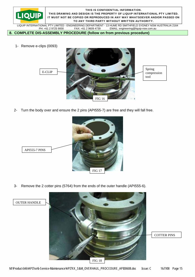
8. COMPLETE DIS-ASSEMBLY PROCEDURE (follow on from previous procedure)
1- Remove e-clips (0093)
Spring compression tool
E-CLIP
FIG 16
2- Turn the body over and ensure the 2 pins (API555-7) are free and they will fall free.
API555-7 PINS
FIG 17
3- Remove the 2 cotter pins (5764) from the ends of the outer handle (API555-6).
OUTER HANDLE
COTTER PINS
FIG 18

THIS IS CONFIDENTIAL INFORMATION. THIS DRAWING AND DESIGN IS THE PROPERTY OF LIQUIP INTERNATIONAL PTY LIMITED.
IT MUST NOT BE COPIED OR REPRODUCED IN ANY WAY WHATSOEVER AND/OR PASSED ON TO ANY THIRD PARTY WITHOUT WRITTEN AUTHORITY.
LIQUIP INTERNATIONAL PTY LIMITED - ENGINEERING DEPARTMENT - 13 HUME RD SMITHFIELD SYDNEY NSW AUSTRALIA 2164 PH: +61 2 9725 9000 FAX: +61 2 9609 4739 EMAIL: [email protected]
M:\Product-Info\API7xx\6-Service-Maintenance\API7XX_S&M_OVERHAUL_PROCEDURE_API00608.doc Issue: C 16/7/08 Page 16
4- Remove the springs and outer handle (API555-6) from the outer body lever (API555-10) and slide the lever from the outer body ring.
SPRINGS
FIG 19 5- To allow the collar to fall free of the body turn the valve so the 8 hole flange face is down then depress the 4 off latches together and the collar will fall free.
FIG 20 6- Inspect the collar for wear, in particular check these areas.
CHECK FOR WEAR
FIG 21

THIS IS CONFIDENTIAL INFORMATION. THIS DRAWING AND DESIGN IS THE PROPERTY OF LIQUIP INTERNATIONAL PTY LIMITED.
IT MUST NOT BE COPIED OR REPRODUCED IN ANY WAY WHATSOEVER AND/OR PASSED ON TO ANY THIRD PARTY WITHOUT WRITTEN AUTHORITY.
LIQUIP INTERNATIONAL PTY LIMITED - ENGINEERING DEPARTMENT - 13 HUME RD SMITHFIELD SYDNEY NSW AUSTRALIA 2164 PH: +61 2 9725 9000 FAX: +61 2 9609 4739 EMAIL: [email protected]
M:\Product-Info\API7xx\6-Service-Maintenance\API7XX_S&M_OVERHAUL_PROCEDURE_API00608.doc Issue: C 16/7/08 Page 17
7- The remaining parts are the latches and latch return springs, these can be removed by knocking the roll pin out until the latch falls free. There should be no reason to remove these latches, as they will not wear significantly to require changing.
LATCHES
FIG 22
API710-1 BODY API700-3 COLLAR API555-7 HANDLE RELEASE API725-4 LATCH 0927 ROLL PIN 4497 COLLAR RETURN SPRING API555-7 GUIDE PIN API555-10 LEVER OUTER FIG 23

THIS IS CONFIDENTIAL INFORMATION. THIS DRAWING AND DESIGN IS THE PROPERTY OF LIQUIP INTERNATIONAL PTY LIMITED.
IT MUST NOT BE COPIED OR REPRODUCED IN ANY WAY WHATSOEVER AND/OR PASSED ON TO ANY THIRD PARTY WITHOUT WRITTEN AUTHORITY.
LIQUIP INTERNATIONAL PTY LIMITED - ENGINEERING DEPARTMENT - 13 HUME RD SMITHFIELD SYDNEY NSW AUSTRALIA 2164 PH: +61 2 9725 9000 FAX: +61 2 9609 4739 EMAIL: [email protected]
M:\Product-Info\API7xx\6-Service-Maintenance\API7XX_S&M_OVERHAUL_PROCEDURE_API00608.doc Issue: C 16/7/08 Page 18
9. COMPLETE RE-ASSEMBLY PROCEDURE 1. Fit o-ring (4501or 4574VG) onto outside of Acetal bush API 513-6 and lightly smear outside of bush and
bore in the body API 7XX-1 with SR grease. Using Jig number 374 fit bush
**ENSURE THAT HEAD OF BUSH IS FLUSH WITH CAST BOSS INSIDE BODY** 2. Fit tetra bearing 2698 into hole in body on opposite side. Bush to be pushed to bottom of hole. 3. Sit body on bench with flange (8 hole) on bench. 4. Fit four (4) springs 6171, into drilled hole in body. Fit the four (4) latches API725-4. Check for movement
and operation of the latch. NOTE: Latch should not rub on the sides of the latch hole. 5. Fit 2 off o-rings (0235, 0235EPDM or 0235VG) onto shaft & handle assembly API 700-2 (long handle) or
API555-2 (short handle) and smear top of o-rings with Shell SR grease 3395. 6. Fit two (2) o-rings (0203, 0203EPDM or 0203VG) and seal (4602VB, 4602EPDM or 4602VG) to poppet
adaptor ring and smear top of o-rings with Shell SR grease or equivalent. Note: Leave o-rings in hot water for 15 minutes to soften and allow easier insertion. The “T” seal (4602VB, 4602EPDM or 4602VG) is to be fitted to top face of poppet adaptor ring. Fit o-rings 0203, 0203EPDM or 0203VG to inside & outside diameter groove of poppet adaptor ring.
**MAKE SURE O-RINGS ARE NOT TWISTED WHEN FITTED TO GROOVES** 7. Fit components to piston poppet API 555-5 as per below figure
CLEVIS PINS
WASHERS & SPLIT PINS
CAM PLATES
FIG 25FIG 24
THIS IS CONFIDENTIAL INFORMATION. THIS DRAWING AND DESIGN IS THE PROPERTY OF LIQUIP INTERNATIONAL PTY LIMITED.
IT MUST NOT BE COPIED OR REPRODUCED IN ANY WAY WHATSOEVER AND/OR PASSED ON TO ANY THIRD PARTY WITHOUT WRITTEN AUTHORITY.
LIQUIP INTERNATIONAL PTY LIMITED - ENGINEERING DEPARTMENT - 13 HUME RD SMITHFIELD SYDNEY NSW AUSTRALIA 2164 PH: +61 2 9725 9000 FAX: +61 2 9609 4739 EMAIL: [email protected]
M:\Product-Info\API7xx\6-Service-Maintenance\API7XX_S&M_OVERHAUL_PROCEDURE_API00608.doc Issue: C 16/7/08 Page 19
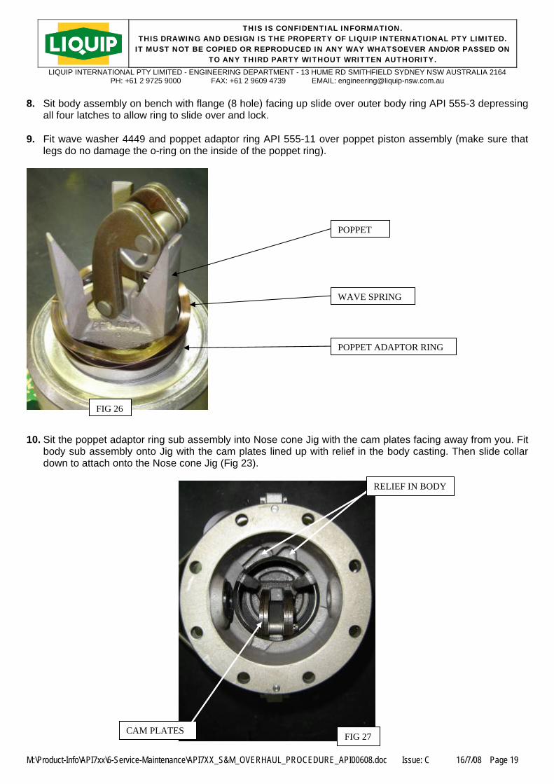
8. Sit body assembly on bench with flange (8 hole) facing up slide over outer body ring API 555-3 depressing
all four latches to allow ring to slide over and lock. 9. Fit wave washer 4449 and poppet adaptor ring API 555-11 over poppet piston assembly (make sure that
legs do no damage the o-ring on the inside of the poppet ring).
POPPET
WAVE SPRING
POPPET ADAPTOR RING
FIG 26 10. Sit the poppet adaptor ring sub assembly into Nose cone Jig with the cam plates facing away from you. Fit
body sub assembly onto Jig with the cam plates lined up with relief in the body casting. Then slide collar down to attach onto the Nose cone Jig (Fig 23).
RELIEF IN BODY
CAM PLATES FIG 27

THIS IS CONFIDENTIAL INFORMATION. THIS DRAWING AND DESIGN IS THE PROPERTY OF LIQUIP INTERNATIONAL PTY LIMITED.
IT MUST NOT BE COPIED OR REPRODUCED IN ANY WAY WHATSOEVER AND/OR PASSED ON TO ANY THIRD PARTY WITHOUT WRITTEN AUTHORITY.
LIQUIP INTERNATIONAL PTY LIMITED - ENGINEERING DEPARTMENT - 13 HUME RD SMITHFIELD SYDNEY NSW AUSTRALIA 2164 PH: +61 2 9725 9000 FAX: +61 2 9609 4739 EMAIL: [email protected]
M:\Product-Info\API7xx\6-Service-Maintenance\API7XX_S&M_OVERHAUL_PROCEDURE_API00608.doc Issue: C 16/7/08 Page 20
Handle
R-clip
R-clip & Handle to point the same way
Washer Shim washer
FIG 28
11. Smear shaft and o-rings of shaft sub-assembly with Shell SR grease and start to enter Acetal bush in body
assembly. Slide shaft through the washer, cam API 513-7 and spacer tube API 555-9. Push shaft through spacer tube holding Acetal bush inside body. Before engaging flats on operating shaft to cam make sure ball on handle is up and vertical. Tap shaft fully home (ensure the tetra bush is not damaged) if difficulty is experienced pushing the shaft home check the tetra bush. Pull handle over towards you and fit R-clip 0946 ensuring that leg of R-clip that wraps around outside of shaft is facing you. Refer to fig 32. Check a couple of times for correct operation.
12. Fit outer body lever and release handle, fit collar return springs, guide pins and e-clips.

THIS IS CONFIDENTIAL INFORMATION. THIS DRAWING AND DESIGN IS THE PROPERTY OF LIQUIP INTERNATIONAL PTY LIMITED.
IT MUST NOT BE COPIED OR REPRODUCED IN ANY WAY WHATSOEVER AND/OR PASSED ON TO ANY THIRD PARTY WITHOUT WRITTEN AUTHORITY.
LIQUIP INTERNATIONAL PTY LIMITED - ENGINEERING DEPARTMENT - 13 HUME RD SMITHFIELD SYDNEY NSW AUSTRALIA 2164 PH: +61 2 9725 9000 FAX: +61 2 9609 4739 EMAIL: [email protected]
M:\Product-Info\API7xx\6-Service-Maintenance\API7XX_S&M_OVERHAUL_PROCEDURE_API00608.doc Issue: C 16/7/08 Page 21
10. TESTING Refer to Document Number API 00908.doc “API Coupler Production and Overhaul Testing” for full details. Where a proper test fixture is not available, responsibility for testing of the coupler lies with the personnel responsible for maintenance and overhaul. Testing must, as minimum include the following: Wet pressure test to 800kPa Air pressure test at 570kPa/50kPa Latch tightness of less than 1.5 degrees arc movement Liquid spillage less than 5ml Interlock test

THIS IS CONFIDENTIAL INFORMATION. THIS DRAWING AND DESIGN IS THE PROPERTY OF LIQUIP INTERNATIONAL PTY LIMITED.
IT MUST NOT BE COPIED OR REPRODUCED IN ANY WAY WHATSOEVER AND/OR PASSED ON TO ANY THIRD PARTY WITHOUT WRITTEN AUTHORITY.
LIQUIP INTERNATIONAL PTY LIMITED - ENGINEERING DEPARTMENT - 13 HUME RD SMITHFIELD SYDNEY NSW AUSTRALIA 2164 PH: +61 2 9725 9000 FAX: +61 2 9609 4739 EMAIL: [email protected]
M:\Product-Info\API7xx\6-Service-Maintenance\API7XX_S&M_OVERHAUL_PROCEDURE_API00608.doc Issue: C 16/7/08 Page 22
11. PERIODIC CHECKS Recommended MONTHLY checks:
1. Visually inspect coupler & loading arm for damage & leaks, particular at the face seal & poppet o-ring, handle shaft & mounting flange.
Recommended SIX MONTHLY checks:
1. Visually inspect coupler & loading arm for damage & leaks, particular at the face seal & poppet o-ring, handle shaft & mounting flange.
2. Check tightness of mounting bolts. Re-torque to 24-27Nm.
3. Check operation of coupler to ensure smooth operation of the collar & handle.
4. After loading, close poppet & un-couple. Check spillage is less than 5mL when disconnecting
from adaptor. Recommended ANNUAL checks:
1. Visually inspect coupler & loading arm for damage & leaks, particular at the face seal & poppet o-ring, handle shaft & mounting flange.
2. Check tightness of mounting bolts. Re-torque to 24-27Nm.
3. Check operation of coupler to ensure smooth operation of the collar & handle.
4. After loading, close poppet & un-couple. Check spillage is less than 5mL when disconnecting
from adaptor.