1004D3/1005E3 API Bottom Loading Coupler · Reference API Standard RP-1004 for additional...
12
1004D3/1005E3 API Bottom Loading Coupler Installation, Operation & Maintenance (IOM) Manual 2726 Henkle Drive • Lebanon, OH 45036 • Phone (800) 547-9393 • (513) 461-0113 • Fax (800) 245-8536 • (513) 932-9845 • www.opw-es.com Document No. H32094PA, Rev. 0 Issue Date: September 4, 2014 Supersedes: March 1, 2013
Transcript of 1004D3/1005E3 API Bottom Loading Coupler · Reference API Standard RP-1004 for additional...

1004D3/1005E3 API Bottom Loading CouplerInstallation, Operation & Maintenance (IOM) Manual
2726 Henkle Drive • Lebanon, OH 45036 • Phone (800) 547-9393 • (513) 461-0113 • Fax (800) 245-8536 • (513) 932-9845 • www.opw-es.com
Document No. H32094PA, Rev. 0Issue Date: September 4, 2014Supersedes: March 1, 2013

2
The 1004D3 is the standard in “drip-less” bottom-loading couplers and a proven performer at major oil terminals worldwide. The 1004D3 mates with all 4” bottom-loading adapters built in accordance with API RP-1004 requirements to significantly reduce liquid loss at disconnect.
1005E3Small handles used throughout Europe
Section 1 Introduction
1004D3Large handles used
throughout the Americas
32726 Henkle Drive • Lebanon, OH 45036 • Phone (800) 547-9393 • (513) 461-0113 • Fax (800) 245-8536 • (513) 932-9845 • www.opw-es.com
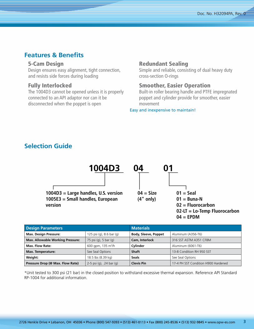
*Unit tested to 300 psi (21 bar) in the closed position to withstand excessive thermal expansion. Reference API Standard RP-1004 for additional information.
Features & Benefits
Selection Guide
5-Cam Design Design ensures easy alignment, tight connection, and resists side forces during loading
Fully Interlocked The 1004D3 cannot be opened unless it is properly connected to an API adaptor nor can it be disconnected when the poppet is open
Redundant Sealing Simple and reliable, consisting of dual heavy duty cross-section O-rings
Smoother, Easier Operation Built-in roller bearing handle and PTFE impregnated poppet and cylinder provide for smoother, easier movement
Easy and inexpensive to maintain!
1004D3 04 01
1004D3 = Large handles, U.S. version1005E3 = Small handles, European version
04 = Size(4" only)
01 = Seal01 = Buna-N02 = Fluorocarbon02-LT = Lo-Temp Fluorocarbon04 = EPDM
Design Parameters MaterialsMax. Design Pressure: 125 psi (g), 8.6 bar (g) Body, Sleeve, Poppet Aluminum (A356-T6)
Max. Allowable Working Pressure: 75 psi (g), 5 bar (g) Cam, Interlock 316 SST ASTM A351 CF8M
Max. Flow Rate: 600 gpm, 135 m3/h Cylinder Aluminum (6061-T6)
Max. Temperature: See Seal Options Shaft 13-8 Condition RH 950 SST
Weight: 18.5 lbs (8.39 kg) Seals See Seal Options
Pressure Drop (@ Max. Flow Rate) 2-5 psi (g), .24 bar (g) Clevis Pin 17-4 PH SST Condition H900 Hardened
Doc. No. H32094PA, Rev. 0

4
4
15
14
22
22
20
21
33
32
28
29
23
27
7
1
2
3
8
6
11
10
5
9
12
24
25
30
31
13
16
19
18
17
52726 Henkle Drive • Lebanon, OH 45036 • Phone (800) 547-9393 • (513) 461-0113 • Fax (800) 245-8536 • (513) 932-9845 • www.opw-es.com
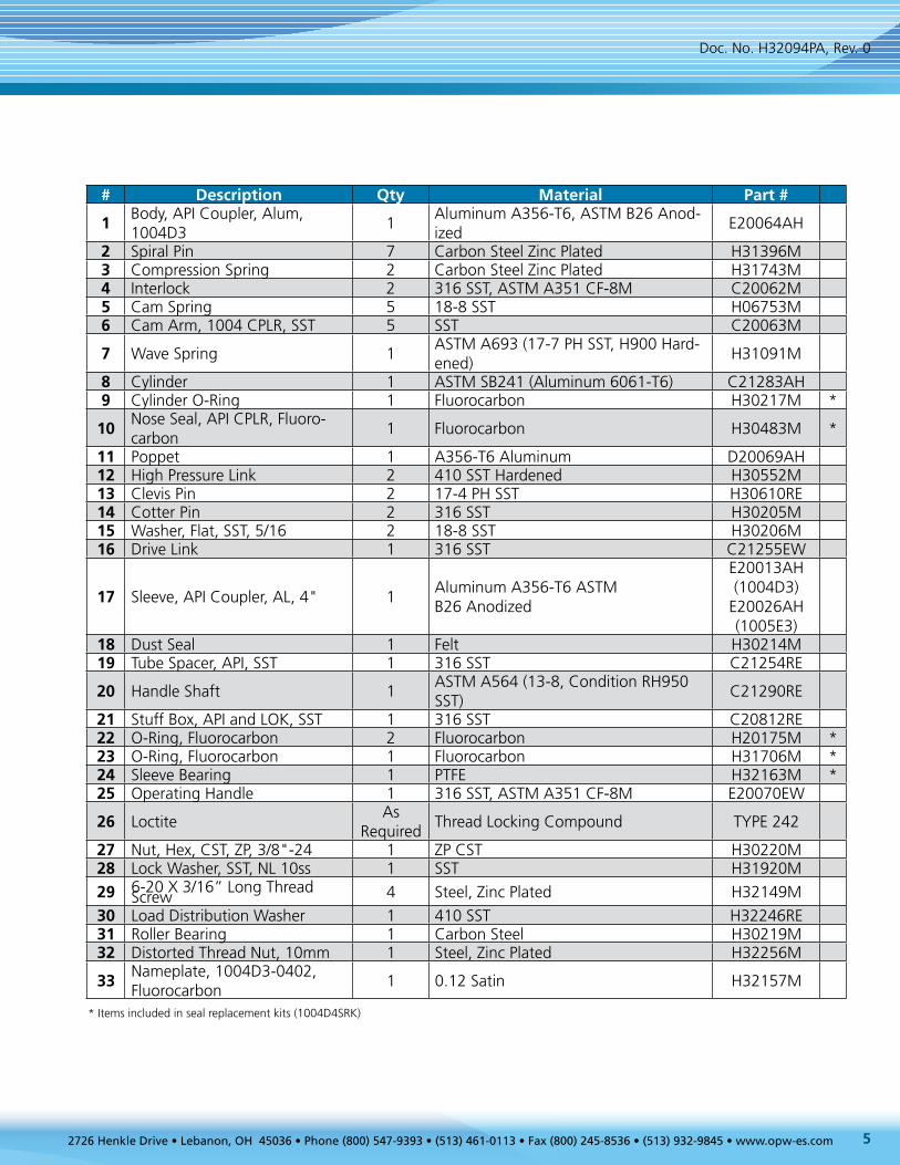
# Description Qty Material Part #
1Body, API Coupler, Alum, 1004D3
1Aluminum A356-T6, ASTM B26 Anod-ized
E20064AH
2 Spiral Pin 7 Carbon Steel Zinc Plated H31396M3 Compression Spring 2 Carbon Steel Zinc Plated H31743M4 Interlock 2 316 SST, ASTM A351 CF-8M C20062M5 Cam Spring 5 18-8 SST H06753M6 Cam Arm, 1004 CPLR, SST 5 SST C20063M
7 Wave Spring 1ASTM A693 (17-7 PH SST, H900 Hard-ened)
H31091M
8 Cylinder 1 ASTM SB241 (Aluminum 6061-T6) C21283AH9 Cylinder O-Ring 1 Fluorocarbon H30217M *
10Nose Seal, API CPLR, Fluoro-carbon
1 Fluorocarbon H30483M *
11 Poppet 1 A356-T6 Aluminum D20069AH12 High Pressure Link 2 410 SST Hardened H30552M13 Clevis Pin 2 17-4 PH SST H30610RE14 Cotter Pin 2 316 SST H30205M15 Washer, Flat, SST, 5/16 2 18-8 SST H30206M16 Drive Link 1 316 SST C21255EW
17 Sleeve, API Coupler, AL, 4" 1Aluminum A356-T6 ASTM B26 Anodized
E20013AH (1004D3)
E20026AH (1005E3)
18 Dust Seal 1 Felt H30214M19 Tube Spacer, API, SST 1 316 SST C21254RE
20 Handle Shaft 1ASTM A564 (13-8, Condition RH950 SST)
C21290RE
21 Stuff Box, API and LOK, SST 1 316 SST C20812RE22 O-Ring, Fluorocarbon 2 Fluorocarbon H20175M *23 O-Ring, Fluorocarbon 1 Fluorocarbon H31706M *24 Sleeve Bearing 1 PTFE H32163M *25 Operating Handle 1 316 SST, ASTM A351 CF-8M E20070EW
26 LoctiteAs
RequiredThread Locking Compound TYPE 242
27 Nut, Hex, CST, ZP, 3/8"-24 1 ZP CST H30220M28 Lock Washer, SST, NL 10ss 1 SST H31920M
29 6-20 X 3/16” Long Thread Screw 4 Steel, Zinc Plated H32149M
30 Load Distribution Washer 1 410 SST H32246RE31 Roller Bearing 1 Carbon Steel H30219M32 Distorted Thread Nut, 10mm 1 Steel, Zinc Plated H32256M
33Nameplate, 1004D3-0402, Fluorocarbon
1 0.12 Satin H32157M
* Items included in seal replacement kits (1004D4SRK)
Doc. No. H32094PA, Rev. 0
6
Section 2 AssemblyInstallation PreparationsIMPORTANT: OPW products should be used in compliance with applicable federal, state, provincial, and local laws and regulations. Product selection should be based on physical specifications and limitations and compatibility with the environment and materials to be handled. OPW MAKES NO WARRANTY OF FITNESS FOR A PARTICULAR USE. All illustrations and specifications in this literature are based on the latest product information available at the time of publication. OPW reserves the right to make changes at any time in prices, materials, specifications and models and to discontinue models without notice or obligation.
Safety Precautions
WARNING: Failure to follow these warnings could result in personal injury, property damage or product failure.
1.) Do not attempt any maintenance service while the equipment is in operation. System pressure must be relieved and the product drained before attempting any service on the unit. The line must be locked out while service is in progress. Proper thermal relief must be provided at all times while equipment is in service.
2.) OPW products do not eliminate possible exposure to hazardous substances. The conditions of handling and use are beyond our control, and we make no guarantee and assume no liability for damages or injuries related to the use of our products. Follow the safety precautions outlined in the Material Safety Data Sheets for the material being used. It is the responsibility of the user to comply with all federal, state and local regulations. Always employ proper safety precautions and handling techniques.
3.) Proper seal and wetted material part selection are critical for safe operation. To assure maximum life for the service intended, use only those materials compatible with the fluids being handled. Please note material being supplied and make certain that it is suited for the intended service.
4.) Read and understand these instructions before starting installation: • Coupling is to be used for its designated purpose only • Local regulations for (un)loading must be followed at all times • Product flow may result in static electricity; grounding of equipment is required • OPW instructions must be followed for installation • Make sure to use adequate personal protection at all times during operation
WARNING

72726 Henkle Drive • Lebanon, OH 45036 • Phone (800) 547-9393 • (513) 461-0113 • Fax (800) 245-8536 • (513) 932-9845 • www.opw-es.com
WARNING
NOTE: All images depict the 1004D3 (large handles). The steps for 1005E3 coupler (small handles) are the same as 1004D3.
Seal Options
Seal Replacement Kits
Assembly Procedure
Seal Material
Coupler Model #Nose Seal
(10)Stuff Box Seal
(22)Stuff Box Seal
(23)Cylinder Seal (9)
Temp Rating
Buna-N 1004D3-0401/1005E3-0401 H30482M H20129M H31705M H30258M -20°F - 250°F (-29°C - 121°C)
Fluorocarbon 1004D3-0402/1005E3-0402 H30483M H20175M H31706M H30217M -20°F - 400°F (-29°C - 204°C)
EPDM 1004D4-0404/1005E3-0404 H31957M H20176M H31707M H31956M -50°F - 225°F (-46°C - 107°C)
Consult factory for additional seal options.
Seal Material Seal Replacement Kit Part #
Buna-N 1004D3SRK-0401
Fluorocarbon 1004D3SRK-0402
Lo-Temp Fluorocarbon 1004D3SRK-0402-LT
EPDM 1004D3SRK-0404
OPW 1004D3SRK Seal Replacement Kits include everything needed to change the seals in the 1004D3/1005E3 API coupler. Seal Replacement Kits are always recommended as spare parts.
Secure whatever device coupler will be mounted to, e.g., loading arm.
Sandwich gasket between coupler and load device flanges.
Align coupler bolt holes with bolt holes on loading device.
Insert two (2) bolts into the highest bolt holes on the flange and hand tighten. This is to secure coupler and prevent damage due to bending as the remain-ing bolts are installed.
WARNING: Under pressure, poppet will cause handle to rotate violently if not restrained.
Step 1 Step 2
Tools Needed
• 11/16-inch or 17-mm socket • 1-1/4-inch or 32-mm deep-reach socket
Connect the coupler to the adapter. Slide the sleeve fully forward. Fully rotate the operating handle and in the open position, the operating handle cam surface should prevent the sleeve from sliding back.
Step 3
NOTICE
Doc. No. H32094PA, Rev. 0
8
Section 3 Maintenance, Disassembly & Reassembly
Disassembly InstructionsStep 1: Dismantle API coupler
CAUTION: Dismantling must be performed by authorized and trained personnel only. CAUTION: The same risks and procedures of initial installation apply.
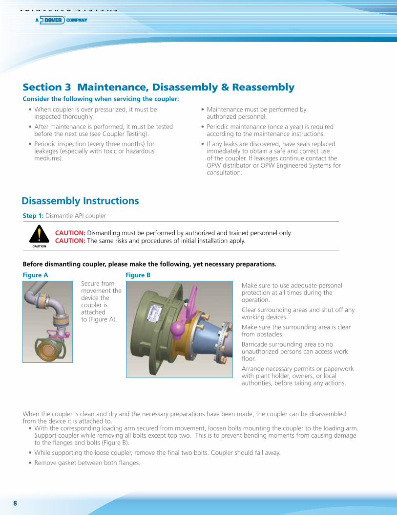
When the coupler is clean and dry and the necessary preparations have been made, the coupler can be disassembled from the device it is attached to.
• With the corresponding loading arm secured from movement, loosen bolts mounting the coupler to the loading arm. Support coupler while removing all bolts except top two. This is to prevent bending moments from causing damage to the flanges and bolts (Figure B).
• While supporting the loose coupler, remove the final two bolts. Coupler should fall away.
• Remove gasket between both flanges.
Before dismantling coupler, please make the following, yet necessary preparations.
Figure A Figure BSecure from movement the device the coupler is attached to (Figure A).
Make sure to use adequate personal protection at all times during the operation.
Clear surrounding areas and shut off any working devices.
Make sure the surrounding area is clear from obstacles.
Barricade surrounding area so no unauthorized persons can access work floor.
Arrange necessary permits or paperwork with plant holder, owners, or local authorities, before taking any actions.
• When coupler is over pressurized, it must be inspected thoroughly.
• After maintenance is performed, it must be tested before the next use (see Coupler Testing).
• Periodic inspection (every three months) for leakages (especially with toxic or hazardous mediums).
• Maintenance must be performed by authorized personnel.
• Periodic maintenance (once a year) is required according to the maintenance instructions.
• If any leaks are discovered, have seals replaced immediately to obtain a safe and correct use of the coupler. If leakages continue contact the OPW distributor or OPW Engineered Systems for consultation.
Consider the following when servicing the coupler:
CAUTION

92726 Henkle Drive • Lebanon, OH 45036 • Phone (800) 547-9393 • (513) 461-0113 • Fax (800) 245-8536 • (513) 932-9845 • www.opw-es.com
Carefully, manually defeat the interlocks and slide the sleeve fully forward. Fully rotate the operating handle.
Remove the load distribution washer, stuff box, seals, and sleeve bearing. Remove the stuff box using the 1-1/4-inch or 32-mm deep-reach socket. Discard the load distribution washer.
Remove the handle shaft through the body being careful to catch the tube spacer. Thoroughly clean the handle shaft and tube spacer and inspect for wear or damage.
Remove the 10 mm nut and the Lock washer using the 11/16-inch or 17-mm deep-reach socket. Discard the nut and Nord-lock washer. Remove operating handle.
Step 2:
Step 4:
Step 5:
Step 3:
Doc. No. H32094PA, Rev. 0
10
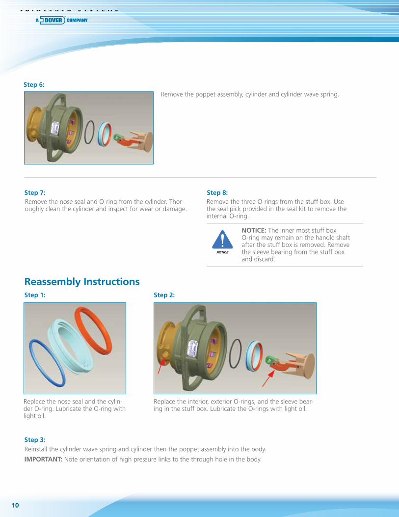
Remove the poppet assembly, cylinder and cylinder wave spring.
Remove the nose seal and O-ring from the cylinder. Thor-oughly clean the cylinder and inspect for wear or damage.
Step 6:
Step 7: Step 8:
Step 1: Step 2:
Step 3:
Remove the three O-rings from the stuff box. Use the seal pick provided in the seal kit to remove the internal O-ring. NOTICE: The inner most stuff box
O-ring may remain on the handle shaft after the stuff box is removed. Remove the sleeve bearing from the stuff box and discard.
Replace the nose seal and the cylin-der O-ring. Lubricate the O-ring with light oil.
Replace the interior, exterior O-rings, and the sleeve bear-ing in the stuff box. Lubricate the O-rings with light oil.
Reinstall the cylinder wave spring and cylinder then the poppet assembly into the body.
IMPORTANT: Note orientation of high pressure links to the through hole in the body.
Reassembly Instructions
NOTICE

112726 Henkle Drive • Lebanon, OH 45036 • Phone (800) 547-9393 • (513) 461-0113 • Fax (800) 245-8536 • (513) 932-9845 • www.opw-es.com
Step 4:
Step 5:
Step 6:
Slide the handle shaft into the body and through the drive link. As the shaft just pokes through the drive link, install the tube spacer. Rotate the shaft until the flats on the shaft and the drive link align and then push the shaft through and into the body.
Install the stuff box using the 1-1/4 inch or 32 mm deep-reach socket. Tighten the stuff box firmly into the body.
Install the new load distribution washer on the handle shaft with the permanent mark toward the assembler. Install the operating handle, the new Lock washer, and new 10-mm nut. Tighten the 10-mm nut using the 11/16-inch or 17 mm deep reach socket to 25 ft-lb or 34 N•m torque.
Step 7:
WARNING: With sleeve forward, operat-ing handle is unlocked and can rotate. Do not apply pressure to handle unless trying to open valve. Use caution when working around handle when system is under pres-sure. Once handle starts moving pressure can cause it to rotate violently.
Coupler assembly is complete.
WARNING
Doc. No. H32094PA, Rev. 0

8
41
3
25
6
7
14
15
161012
1113
9
OPW Global Operations1 OPW Corporate Headquarters
2 OPW Fuel Management Systems
3 OPW Retail Fueling
4 OPW Engineered Systems
5 Midland Manufacturing
6 Civacon
7 PDQ Manufacturing Inc.
8 OPW Mexico
9 OPW Latin America
10 Poland/Petro Vend of Poland, Inc.
11 OPW EMEA Headquarters
12 OPW EMEA Czech Republic
13 OPW FTG Europe
14 OPW India
15 OPW Asia Pacific
16 OPW Russia
2726 Henkle Drive Lebanon, OH 45036, USA Phone: +1 (800) 547-9393 Fax: +1 (800) 245-8536www.opw-es.com
www.opw-es.com
Leading The Way in Fluid Handling Solutions Worldwide