
Liquid Leakage Sensor Amplifiers - Omron...1 New Product Liquid Leakage Sensor Amplifiers K7L Series...
26
1 New Product Liquid Leakage Sensor Amplifiers K7L Series Reliable Sensitive Liquid Sensors for Stable Detection of Liquid Chemicals with Low Conductivity and Water Leakage • A lineup of new models compatible with Push-In Plus Terminal Block Sockets is available. • UL listed when used with Push-In Plus Terminal Block Sockets. • Sensor disconnection detection (K7L-AT50D@@/- UD@@). • Models for long-distance wiring to 400 m. • Ribbon Electrode Bands and Point Sensors available. Model Number Legend *1. The applicable models of the K7L depend on the model of the Socket. If the correct Socket is not used, the K7L nameplate will be upside down. *2. The UL listing applies only when the Sensor is used in combination with a Push-In Socket (P2RF-08-PU). By itself, the K7L is UL recognized. For the most recent information on models that have been certified for safety standards, refer to your OMRON website. K7L-AT50@@ K7L-U@@ K7L-@@B K7L-@@@@ @ @ (1) (2) (3) (1) (2) (3) Symbol Meaning Symbol Meaning Output Symbol Meaning NPN connection PNP connection (Equivalent) AT50 Standard wiring distance Blank No sensor disconnection detection OK OK Blank For Screw Terminal Block Socket U Long wiring distance D Sensor disconnection detection OK NG B For Push-In Plus Terminal Block Socket DP Sensor disconnection detection Supports plus common connection NG OK Wiring distance Disconnection detection Socket terminals (*1) Standards Model Standard usage Wiring cable: 50 m max. Sensing Bands: 10 m max. Not supported. Screw Terminal Block P2RF-08/-08-E K7L-AT50 Push-In Plus Terminal Block P2RF-08-PU K7L-AT50B Supported. Screw Terminal Block P2RF-08/-08-E K7L-AT50D K7L-AT50DP Push-In Plus Terminal Block P2RF-08-PU K7L-AT50DB K7L-AT50DPB Long distance use Total Length of Wiring Cable and Sensing Bands: 400 m max. Not supported. Screw Terminal Block P2RF-08/-08-E K7L-U Push-In Plus Terminal Block P2RF-08-PU K7L-UB Supported. Screw Terminal Block P2RF-08/-08-E K7L-UD K7L-UDP Push-In Plus Terminal Block P2RF-08-PU K7L-UDB K7L-UDPB (*2) (*2) (*2) (*2) (*2) (*2)
Transcript of Liquid Leakage Sensor Amplifiers - Omron...1 New Product Liquid Leakage Sensor Amplifiers K7L Series...
1
New Product
Liquid Leakage Sensor AmplifiersK7L Series
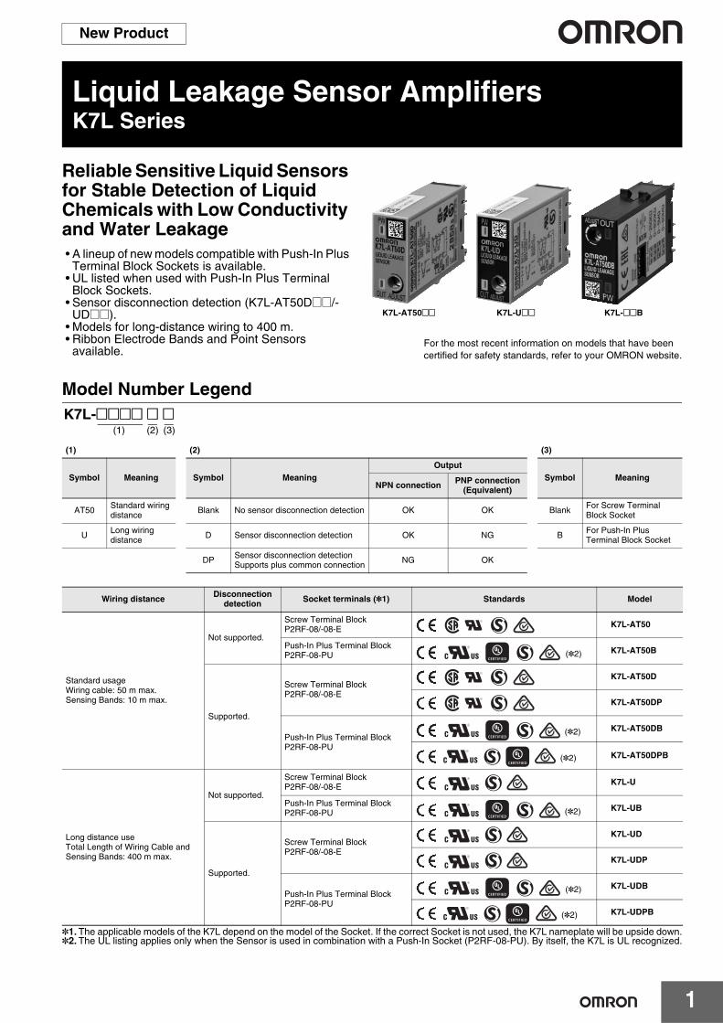
Reliable Sensitive Liquid Sensors for Stable Detection of Liquid Chemicals with Low Conductivity and Water Leakage• A lineup of new models compatible with Push-In Plus
Terminal Block Sockets is available.• UL listed when used with Push-In Plus Terminal
Block Sockets.• Sensor disconnection detection (K7L-AT50D@@/-
UD@@).• Models for long-distance wiring to 400 m.• Ribbon Electrode Bands and Point Sensors
available.
Model Number Legend
*1.The applicable models of the K7L depend on the model of the Socket. If the correct Socket is not used, the K7L nameplate will be upside down.*2.The UL listing applies only when the Sensor is used in combination with a Push-In Socket (P2RF-08-PU). By itself, the K7L is UL recognized.
For the most recent information on models that have been certified for safety standards, refer to your OMRON website.
K7L-AT50@@ K7L-U@@ K7L-@@B
K7L-@@@@ @ @ (1) (2) (3)
(1) (2) (3)
Symbol Meaning Symbol MeaningOutput
Symbol MeaningNPN connection PNP connection
(Equivalent)
AT50 Standard wiring distance Blank No sensor disconnection detection OK OK Blank For Screw Terminal
Block Socket
U Long wiring distance D Sensor disconnection detection OK NG B For Push-In Plus
Terminal Block Socket
DP Sensor disconnection detectionSupports plus common connection NG OK
Wiring distance Disconnection detection Socket terminals (*1) Standards Model
Standard usageWiring cable: 50 m max.Sensing Bands: 10 m max.
Not supported.
Screw Terminal BlockP2RF-08/-08-E K7L-AT50
Push-In Plus Terminal BlockP2RF-08-PU K7L-AT50B
Supported.
Screw Terminal BlockP2RF-08/-08-E
K7L-AT50D
K7L-AT50DP
Push-In Plus Terminal BlockP2RF-08-PU
K7L-AT50DB
K7L-AT50DPB
Long distance useTotal Length of Wiring Cable and Sensing Bands: 400 m max.
Not supported.
Screw Terminal BlockP2RF-08/-08-E K7L-U
Push-In Plus Terminal BlockP2RF-08-PU K7L-UB
Supported.
Screw Terminal BlockP2RF-08/-08-E
K7L-UD
K7L-UDP
Push-In Plus Terminal BlockP2RF-08-PU
K7L-UDB
K7L-UDPB
(*2)
(*2)
(*2)
(*2)
(*2)
(*2)
2
Liquid Leakage Sensor Amplifier/Liquid Leakage Sensor Amplifier with Disconnection Detection Function
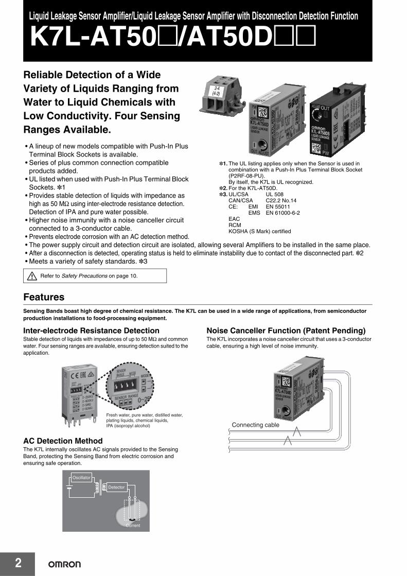
K7L-AT50@/AT50D@@Reliable Detection of a Wide Variety of Liquids Ranging from Water to Liquid Chemicals with Low Conductivity. Four Sensing Ranges Available.
• A lineup of new models compatible with Push-In Plus Terminal Block Sockets is available.
• Series of plus common connection compatible products added.
• UL listed when used with Push-In Plus Terminal Block Sockets. *1
• Provides stable detection of liquids with impedance as high as 50 MΩ using inter-electrode resistance detection. Detection of IPA and pure water possible.
• Higher noise immunity with a noise canceller circuit connected to a 3-conductor cable.
• Prevents electrode corrosion with an AC detection method.• The power supply circuit and detection circuit are isolated, allowing several Amplifiers to be installed in the same place.• After a disconnection is detected, operating status is held to eliminate instability due to contact of the disconnected part. *2• Meets a variety of safety standards. *3
FeaturesSensing Bands boast high degree of chemical resistance. The K7L can be used in a wide range of applications, from semiconductor production installations to food-processing equipment.
Inter-electrode Resistance DetectionStable detection of liquids with impedances of up to 50 MΩ and common water. Four sensing ranges are available, ensuring detection suited to the application.
AC Detection MethodThe K7L internally oscillates AC signals provided to the Sensing Band, protecting the Sensing Band from electric corrosion and ensuring safe operation.
Noise Canceller Function (Patent Pending)The K7L incorporates a noise canceller circuit that uses a 3-conductor cable, ensuring a high level of noise immunity.
*1. The UL listing applies only when the Sensor is used in combination with a Push-In Plus Terminal Block Socket (P2RF-08-PU).By itself, the K7L is UL recognized.
*2. For the K7L-AT50D.*3.UL/CSA UL 508
CAN/CSA C22.2 No.14CE: EMI EN 55011
EMS EN 61000-6-2EACRCMKOSHA (S Mark) certified
Refer to Safety Precautions on page 10.
Fresh water, pure water, distilled water, plating liquids, chemical liquids, IPA (isopropyl alcohol)
Detector
Current
Oscillator
Connecting cable
K7L-AT50@/AT50D@@
3
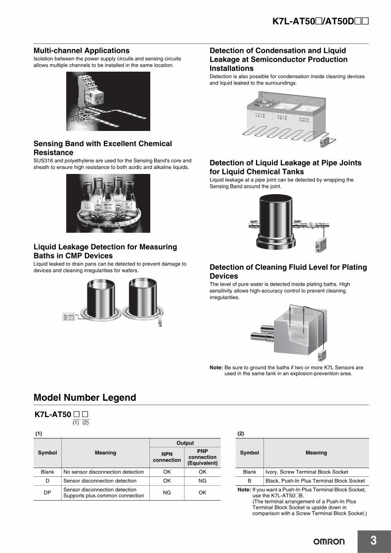
Multi-channel ApplicationsIsolation between the power supply circuits and sensing circuits allows multiple channels to be installed in the same location.
Sensing Band with Excellent Chemical ResistanceSUS316 and polyethylene are used for the Sensing Band's core and sheath to ensure high resistance to both acidic and alkaline liquids.
Liquid Leakage Detection for Measuring Baths in CMP DevicesLiquid leaked to drain pans can be detected to prevent damage to devices and cleaning irregularities for wafers.
Detection of Condensation and Liquid Leakage at Semiconductor Production InstallationsDetection is also possible for condensation inside cleaning devices and liquid leaked to the surroundings.
Detection of Liquid Leakage at Pipe Joints for Liquid Chemical TanksLiquid leakage at a pipe joint can be detected by wrapping the Sensing Band around the joint.
Detection of Cleaning Fluid Level for Plating DevicesThe level of pure water is detected inside plating baths. High sensitivity allows high-accuracy control to prevent cleaning irregularities.
Note: Be sure to ground the baths if two or more K7L Sensors are used in the same tank in an explosion-prevention area.
Model Number Legend
K7L-AT50 @ @ (1) (2)
(1) (2)
Symbol Meaning
Output
Symbol MeaningNPN connection
PNP connection (Equivalent)
Blank No sensor disconnection detection OK OK Blank Ivory, Screw Terminal Block Socket
D Sensor disconnection detection OK NG B Black, Push-In Plus Terminal Block Socket
DP Sensor disconnection detectionSupports plus common connection NG OK Note: If you want a Push-In Plus Terminal Block Socket,
use the K7L-AT50@B. (The terminal arrangement of a Push-In Plus Terminal Block Socket is upside down in comparison with a Screw Terminal Block Socket.)
K7L-AT50@/AT50D@@
4
Ordering Information
*1.Accessories are provided. Check the accessories listed in the specifications for details.*2. The applicable models of the K7L depend on the model of the Socket. If the correct Socket is not used, the K7L nameplate will be upside down.
Characteristics
Specifications
* For the K7L-AT50D@@.
Product name Model
Amplifier
Liquid Leakage Sensor Amplifier *1K7L-AT50K7L-AT50B
Liquid Leakage Sensor Amplifierwith Disconnection Detection Function *1
K7L-AT50DK7L-AT50DPK7L-AT50DBK7L-AT50DPB
Sensors
Sensing Band
F03-15F03-16PEF03-16PTF03-16SFF03-16SFC
Point Sensor(for K7L-AT50/AT50B)
F03-16PSF03-16PS-F
Mounting Brackets and StickersSensing Band Stickers
F03-25F03-26PESF03-26PENF03-26PTN
Point Sensor Mounting Brackets F03-26PS
Socket *2 (for K7L-AT50/AT50D)Round terminals can be used. P2RF-08Round terminals cannot be used. P2RF-08-E
Socket *2 (for K7L-AT50B/AT50DB) Push-In Plus Terminal P2RF-08-PUTerminal Blocks F03-20Terminator F03-20T
Ambient temperature Operating: –10 to +55°C
Ambient humidity Operating: 45% to 85%
Insulation resistance 10 MΩ at 100 VDC between case and current-carrying parts
Dielectric strength 1,000 VAC at 50/60 Hz for 1 min between case and current-carrying parts
Power consumption 1 W max.
Response timeOperate: 800 ms max. Release: 800 ms max.When turning ON power: 2 s max.
Weight Approx. 14 g
Rated power supply voltage 12 to 24 VDC (Allowable voltage fluctuation range: 10 to 30 VDC)
Operate resistance
0 Ω to 50 MΩ, variableRange 0: 0 to 250 kΩ. Range 1: 0 to 600 kΩRange 2: 0 to 5 kΩ. Range 3: 0 to 50 kΩNote: The range is set using the DIP switch on the side of the Sensor Amplifier. (Refer to DIP Switch Settings.)
Set the corresponding pin of the DIP switch in the up position. (For range 0, set all 3 pins in the down position.) The adjuster (ADJUST) on the top of the Sensor Amplifier sets the resistance value for detection within the set range. It is factory-set to the upper limit. (Normally, the K7L can be used with the adjuster at this setting.) With any range, resistance values can be set from 0 Ω.
Disconnection detection function *
Detection signal: 10 VDC max., 200 msDetection time: 10 s max.Recovery: Operation is recovered by resetting the power supply.
Release resistance 105% min. of operate resistance
Output configuration
Open-collector transistor output with 100 mA at 30 VDC max. for both liquid leakage detection and disconnection detection.Max. 30 VDC, 100mANote: If the rightmost pin of the DIP switch on the side of the Sensor Amplifier is set to the down position, the output
turns ON when liquid is detected; if it is set to the up position, the output turns OFF when liquid is detected.
Wiring distance
Connecting cable: 50 m max.Sensing Band length: 10 m max.Note: These values are possible on condition that a completely insulated 3-conductor VCT cable with a thickness of 0.75
mm2 and a dielectric strength of 600 V is used together with a Liquid Sensing Band specified by OMRON. (A 0.2-mm2 cable can also be used.)
Accessories
Terminal Block Screwdriver for ADJUST TerminatorK7L-AT50/AT50B 1 1 ---K7L-AT50D/AT50DB/AT50DP/AT50DPB 1 1 1
K7L-AT50D-S 1 1 ---
K7L-AT50@/AT50D@@
5
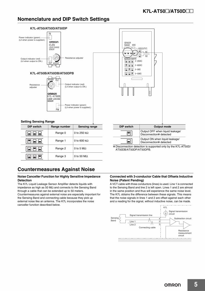
Nomenclature and DIP Switch Settings
Countermeasures Against NoiseNoise Canceller Function for Highly Sensitive Impedance DetectionThe K7L Liquid Leakage Sensor Amplifier detects liquids with impedance as high as 50 MΩ and connects to the Sensing Band through a cable that can be extended up to 50 meters. Countermeasures against external noise are especially important for the Sensing Band and connecting cable because they pick up external noise like an antenna. The K7L incorporates the noise canceller function described below.
Connected with 3-conductor Cable that Offsets Inductive Noise (Patent Pending)A VCT cable with three conductors (lines) is used. Line 1 is connected to the Sensing Band and line 2 is left open. Lines 1 and 2 are almost in the same position and thus will experience the same noise level. The K7L obtains the difference between these signals. This means that the noise signals in lines 1 and 2 are offset against each other and a reading for the signal, without inductive noise, can be made.
K7L-AT50LIQUID LEAKAGESENSOR
PW
OUT ADJUST
Power indicator (green)(Lit when power is supplied.)
Output indicator (red)(Lit when output is ON.)
Resistance adjuster
Power indicator (green)(Lit when power is supplied.)
Output indicator (red)(Lit when output is ON.)
Resistance adjuster
SENSOR RANGE
SENSORRANGE MODE
MODE(OUTPUT)
NC
NO
K7L-AT50/AT50D/AT50DP
K7L-AT50B/AT50DB/AT50DPB
Setting Sensing Range
* Disconnection detection is supported only by the K7L-AT50D/AT50DB/AT50DP/AT50DPB.
DIP switch Range number Sensing range
Range 0 0 to 250 kΩ
Range 1 0 to 600 kΩ
Range 2 0 to 5 MΩ
Range 3 0 to 50 MΩ
DIP switch Output mode
Output OFF when liquid leakage/Disconnection* detected
Output ON when liquid leakage/Disconnection* detected
Sensing Band
Subtraction circuit
Resistance measurement circuit
Signal transmission circuit
Signal transmission line
423
Line 1
Line 2Connecting cable
K7L
K7L-AT50@/AT50D@@
6
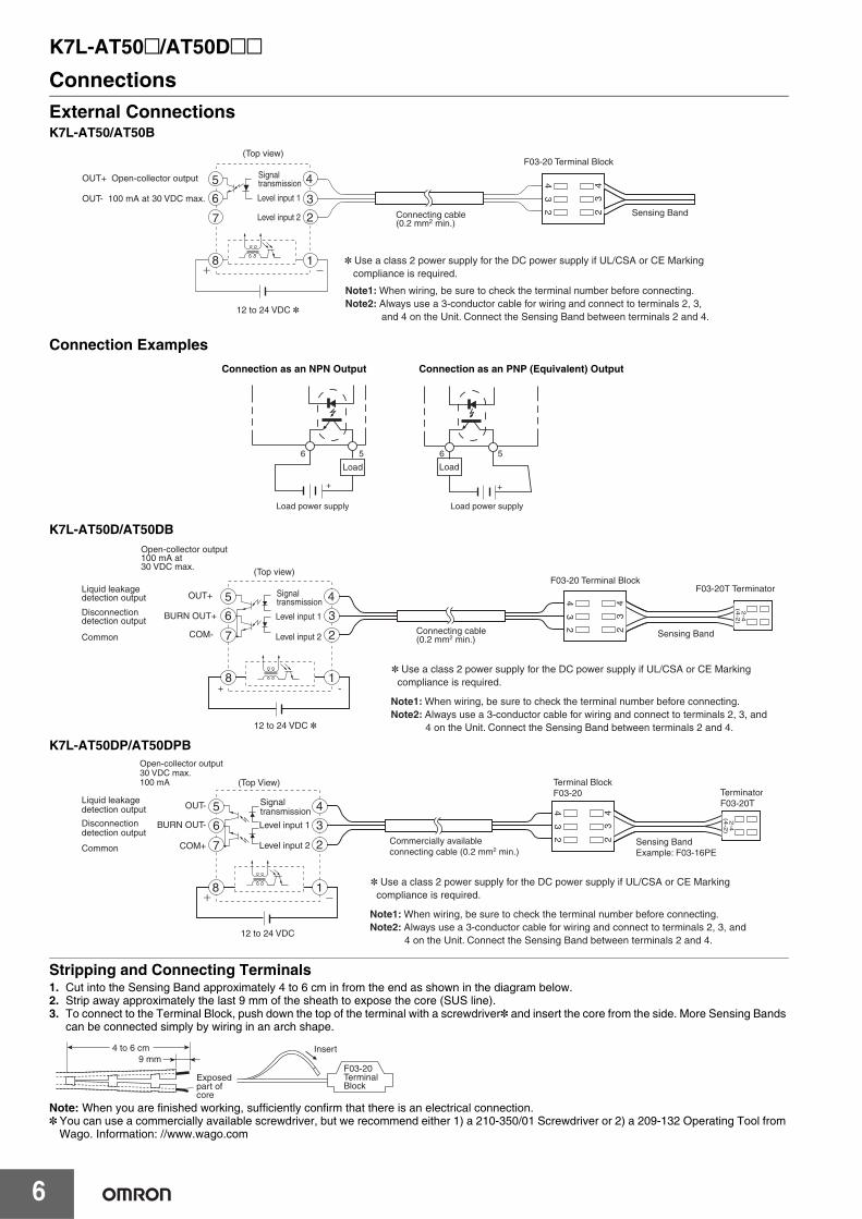
ConnectionsExternal ConnectionsK7L-AT50/AT50B
Connection Examples
K7L-AT50D/AT50DB
K7L-AT50DP/AT50DPB
Stripping and Connecting Terminals1. Cut into the Sensing Band approximately 4 to 6 cm in from the end as shown in the diagram below.2. Strip away approximately the last 9 mm of the sheath to expose the core (SUS line).3. To connect to the Terminal Block, push down the top of the terminal with a screwdriver* and insert the core from the side. More Sensing Bands
can be connected simply by wiring in an arch shape.
Note: When you are finished working, sufficiently confirm that there is an electrical connection.* You can use a commercially available screwdriver, but we recommend either 1) a 210-350/01 Screwdriver or 2) a 209-132 Operating Tool from
Wago. Information: //www.wago.com
23
442
3
5
6
7
8 1
2
3
4
* Use a class 2 power supply for the DC power supply if UL/CSA or CE Marking compliance is required.
Note1: When wiring, be sure to check the terminal number before connecting.Note2: Always use a 3-conductor cable for wiring and connect to terminals 2, 3,
and 4 on the Unit. Connect the Sensing Band between terminals 2 and 4.
(Top view)
12 to 24 VDC *
Connecting cable(0.2 mm2 min.)
F03-20 Terminal Block
Sensing Band
OUT+ Open-collector output
OUT- 100 mA at 30 VDC max.
Signal transmission
Level input 1
Level input 2
Load Load
Load power supply Load power supply
+
6 5
+
6 5
Connection as an NPN Output Connection as an PNP (Equivalent) Output
23
442
3
5
6
7
8
4
3
2
1+ -
(4-2
)2
-4
Connecting cable(0.2 mm2 min.)
F03-20 Terminal Block
Sensing Band
F03-20T Terminator
Open-collector output100 mA at 30 VDC max. (Top view)
Liquid leakage detection output
Disconnection detection output
Common
OUT+
BURN OUT+
COM-
Signal transmission
Level input 1
Level input 2
12 to 24 VDC *
* Use a class 2 power supply for the DC power supply if UL/CSA or CE Marking compliance is required.
Note1: When wiring, be sure to check the terminal number before connecting.Note2: Always use a 3-conductor cable for wiring and connect to terminals 2, 3, and
4 on the Unit. Connect the Sensing Band between terminals 2 and 4.
8
23
442
3
5
6
7
4
3
2
1
(4-2
)2
-4
(Top View)
Signal transmission
Level input 1
Level input 2
Liquid leakage detection output
Disconnection detection output
Common
OUT-
BURN OUT-
COM+
12 to 24 VDC
Commercially available connecting cable (0.2 mm2 min.)
Terminal BlockF03-20
Sensing BandExample: F03-16PE
TerminatorF03-20T
Open-collector output30 VDC max.100 mA
* Use a class 2 power supply for the DC power supply if UL/CSA or CE Marking compliance is required.
Note1: When wiring, be sure to check the terminal number before connecting.Note2: Always use a 3-conductor cable for wiring and connect to terminals 2, 3, and
4 on the Unit. Connect the Sensing Band between terminals 2 and 4.
9 mm
Exposed part of core
Insert
F03-20 Terminal Block
4 to 6 cm

K7L-AT50@/AT50D@@
7
Disconnection detection function (K7L-AT50D/AT50DB/AT50DP/AT50DPB only)Operation While Monitoring for Liquid Leakage• Short-wave signals (2.5 VAC, 3.75 Hz) for liquid leakage detection
are output from terminal 4 of the K7L.• When there is no liquid leakage, the liquid leakage detection
signals that are output are interrupted by the Terminator and the core of the Sensing Band will form an open loop.
Operation at Liquid Leakage Detection• When liquid leakage occurs within the sensing range, the liquid
leakage detection signals output from terminal 4 are input to terminal 2 through the leaked liquid.
• The voltage of the input signals will vary with the resistance of the leaked liquid. This voltage is compared with the detection level set at the K7L.
• If the K7L determines from the comparison results that there is liquid leakage, the liquid leakage output will turn ON or OFF. (The output can be set to NO or NC operation.) The output indicator will turn ON and OFF together with the output. The indicator lights when the output turns ON.
Operation While Monitoring for Disconnection• Output of disconnection detection signals starts within 2 s of power
being supplied to the K7L and is repeated at 7-s intervals.• Disconnection signals are DC signals of 10 V max. that are output
for approximately 200 ms. During this time, the K7L is in disconnection monitoring mode, i.e. it monitors for disconnections only and the liquid leakage detection signals are stopped.
• If there is no disconnection, the disconnection detection signals (10 VDC) that are output pass through the Terminator and return to the K7L. The K7L takes this as normal, i.e., there is no disconnection.
Operation at Disconnection Detection• If there is a disconnection, the signals will be interrupted at the
place where the disconnection occurred, and will not return to the K7L.
• If the signals do not return when the K7L is in disconnection monitoring mode, it will determine that a disconnection has occurred. The output indicator will flash, and the disconnection output will turn ON/OFF depending on the position of the DIP switch (right).
23
442
3
5
6
7
8
4
3
2
1K7L
2.5 VAC (3.75 Hz) Signals interrupted byTerminator.
23
442
3
5
6
7
8
4
3
2
1
K7L
23
442
3
5
6
7
8
4
3
2
1
K7L
10 VDC max., 200 ms
Disconnection detection signals are not interrupted by the Terminator and return to the K7L.
23
442
3
5
6
7
8
4
3
2
1
Signals are interrupted where the disconnection occurred.
K7L
Note: 1. Disconnection detection is only performed between terminals 2 and 4. Therefore, be sure to connect the Sensing Band between terminals 2 and 4.
2. The K7L will switch from liquid leakage detection to disconnection detection if either of the following conditions occur while liquid leakage is detected.2-1. Disconnection occurs between the K7L and the place where liquid is leaked.2-2. While liquid leakage is detected, disconnection occurs between the place where liquid is leaked and the Terminator (F03-20T)
and, subsequently, the leaked liquid is removed (e.g., wiped up or dried).3. During disconnection detection, liquid leakage will not be detected. Once disconnection has been detected, reset the power supply to
stop disconnection detection.
K7L-AT50@/AT50D@@
8
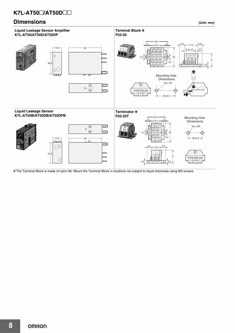
Dimensions (Unit: mm)
* The Terminal Block is made of nylon 66. Mount the Terminal Block in locations not subject to liquid chemicals using M3 screws.
12.8
28.8
46
Liquid Leakage Sensor AmplifierK7L-AT50/AT50D/AT50DP
29.1
23.13 3
3.2
3.2
25
5×3=15 2.5
3.5
17.55.8
17
5.8
23±0.2
Two, M3
Mounting Hole Dimensions
Terminal Block *F03-20
12.8
28.8
46
Liquid Leakage SensorK7L-AT50B/AT50DB/AT50DPB
3.2
3.2
25
24.1
18.13 3
3.53.5
12.55.8
17
5.8
18±0.2
Two, M3
Mounting Hole Dimensions
Terminator *F03-20T

K7L-AT50@/AT50D@@
9
(TOP VIEW)
TerminalArrangement
2 4 dia.9.5
35.5
19.5
30 max.
54 max.
7
Eight, M3.5 x 8
19.5 max.
71.5 max.
31.5
4
21
78
34
65
73 max.
Track-mounted Sockets *P2RF-08 (Round terminals can be used.)
Note: Secure the Sockets with M3 screws at a torque of 0.78 to 1.18 N⋅m.* The applicable models of the K7L depend on the model of the Socket. If
the correct Socket is not used, the K7L nameplate will be upside down.
164
85.5max.
3.5 dia. hole
2 1.5M3 screws
1
8
4
2
3
5
7
6
(A2)
(A1)
(24) (14)
(12)(22)
(11)(21)
Figures in parentheses indicate DIN standard numbers.
11.5
61 max.
35.5
39.5
3 dia.
248 max.
84 max.(Including height of DIN track)
(TOP VIEW)Terminal Arrangement
Track-mounted Sockets *P2RF-08-E
Note: Secure the Sockets with M3 screws at a torque of 0.78 to 1.18 N⋅m.* The applicable models of the K7L depend on the model of the Socket. If
the correct Socket is not used, the K7L nameplate will be upside down.
83
Terminal Arrangement/Internal Connection Diagram
(TOP VIEW)
14
22
24
21
12
11
A1A2(8)(1)
(2) (7)
(4) (5)
(3) (6)15.5
90
(4.2)
(4.2)
57.5
27.35
35.3
53.1
28.125.6
30.8
4334.3
25.6
52.1
3.9
Track-mounted SocketsP2RF-08-PU
Note: The applicable models of the K7L depend on the model of the Socket. If the correct Socket is not used, the K7L nameplate will be upside down.
Note: The numbers in parentheses are traditionally used terminal numbers.
10 8
2
32 dia. 5.5 dia.
Overall length2,000 mm
2.6-dia. vinyl-insulated round cable with 2 conductors
Conductor cross section: 0.079 mm2
Sheath: Fluoroplastic, 0.66 dia.
Electrode
Liquid Leakage Point SensorF03-16PSF03-16PS-F
Bottom View
19.2
38.85
10
1222.5
6 dia.
R3
24 1
R5
1
Glued surface *
Point Sensor Mounting BracketF03-26PS
* Use a commercially available bonding agent for PVC.Do not use adhesive tape for securing.
K7L-AT50@/AT50D@@
10
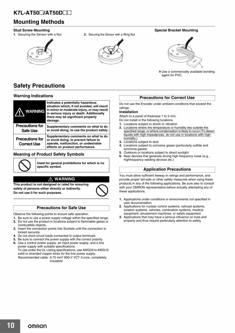
Mounting Methods
Safety Precautions
Warning Indications
Meaning of Product Safety Symbols
This product is not designed or rated for ensuring safety of persons either directly or indirectly.Do not use it for such purposes.
Observe the following points to ensure safe operation.1. Be sure to use a power supply voltage within the specified range.2. Do not use the product in locations subject to flammable gases or
combustible objects.3. Insert the connection points into Sockets until the connection is
locked securely.4. Do not short-circuit loads connected to output terminals.5. Be sure to connect the power supply with the correct polarity.6. Use a control power supply, an input power supply, and a line
power supply with suitable specifications.To use under the UL Listing specifications, use AWG20 to AWG16 solid or stranded copper wires for the line power supply.Recommended cable: 0.75 mm2 600-V VCT 3-core, completely
insulated
Do not use the Encoder under ambient conditions that exceed the ratings.InstallationAttach to a panel of thickness 1 to 5 mm.Do not install in the following locations.1. Locations subject to shock or vibration2. Locations where the temperature or humidity lies outside the
specified range, or where condensation is likely to occur (To detect liquids with high impedances, do not use in locations with high humidity.)
3. Locations subject to dust4. Locations subject to corrosive gases (particularly sulfide and
ammonia gases)5. Outdoors or locations subject to direct sunlight6. Near devices that generate strong high-frequency noise (e.g.,
highfrequency welding devices etc.)
You must allow sufficient leeway in ratings and performance, and provide proper fail-safe or other safety measures when using these products in any of the following applications. Be sure also to consult with your OMRON representative before actually attempting any of these applications.
1. Applications under conditions or environments not specified in user documentation
2. Applications for nuclear control systems, railroad systems, aviation systems, vehicles, combustion systems, medical equipment, amusement machines, or safety equipment
3. Applications that may have a serious influence on lives and property and thus require particularly attention to safety
*
Stud Screw Mounting1. Securing the Sensor with a Nut 2. Securing the Sensor with a Wing Nut
Special Bracket Mounting
* Use a commercially available bonding agent for PVC.
WARNING
Indicates a potentially hazardous situation which, if not avoided, will result in minor or moderate injury, or may result in serious injury or death. Additionally there may be significant property damage.
Precautions for Safe Use
Supplementary comments on what to do or avoid doing, to use the product safely.
Precautions for Correct Use
Supplementary comments on what to do or avoid doing, to prevent failure to operate, malfunction, or undesirable effects on product performance.
Used for general prohibitions for which is no specific symbol.
WARNING
Precautions for Safe Use
Precautions for Correct Use
Application Precautions
K7L-AT50@/AT50D@@
11
Liquid Leakage Sensor Amplifier K7L Q&ASome questions that are frequently asked about the K7L are given below. Use this information when selecting a model.
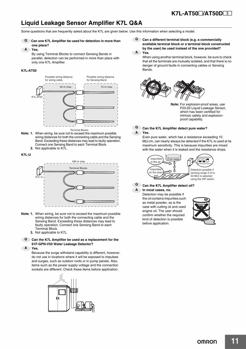
Can one K7L Amplifier be used for detection in more than one place?Yes.By using Terminal Blocks to connect Sensing Bands in parallel, detection can be performed in more than place with only one K7L Amplifier.
K7L-AT50
Note: 1. When wiring, be sure not to exceed the maximum possible wiring distances for both the connecting cable and the Sensing Band. Exceeding these distances may lead to faulty operation. Connect one Sensing Band to each Terminal Block.
2. Not applicable to K7L.
K7L-U
Note: 1. When wiring, be sure not to exceed the maximum possible wiring distances for both the connecting cable and the Sensing Band. Exceeding these distances may lead to faulty operation. Connect one Sensing Band to each Terminal Block.
2. Not applicable to K7L.
Can the K7L Amplifier be used as a replacement for the 61F-GPN-V50 Water Leakage Detector?Yes.Because the surge withstand capability is different, however, do not use in locations where it will be exposed to impulses and surges, such as outdoor roofs or in pump panels. Also, items such as the power supply voltage and the connection sockets are different. Check these items before application.
Can a different terminal block (e.g. a commercially available terminal block or a terminal block constructed by the user) be used instead of the one provided?Yes.When using another terminal block, however, be sure to check that all the terminals are mutually isolated, and that there is no danger of ground faults in connecting cables or Sensing Bands.
Can the K7L Amplifier detect pure water?Yes.Even pure water, which has a resistance exceeding 10 MΩ⋅cm, can nearly always be detected if the K7L is used at its maximum sensitivity. This is because impurities are mixed with the water when it is leaked and the resistance drops.
Can the K7L Amplifier detect oil?In most cases, no.Detection may be possible if the oil contains impurities such as metal powder, as is the case with cutting oil and used engine oil. The user should confirm whether the required kind of detection is possible before application.
Q
A
Possible wiring distance for wiring cable.
50 m max. 10 m max.
Terminal Blocks
K7L-AT50
Possible wiring distance for Sensing Band.
Terminal Blocks
400 m max.
K7L-U
Q
A
Q
A
Note: For explosion-proof areas, use F03-20 Liquid Leakage Sensor, which has been certified for intrinsic safety and explosion-proof capability.
QA
Pure water
Detection possible if sensing range 3 (0 to 50 MΩ) is selected using the DIP switch.
Impurities in the air
Impurities on the drain
pan
Q
A
12
Liquid Leakage Sensor Amplifiers for Long-distance Wiring
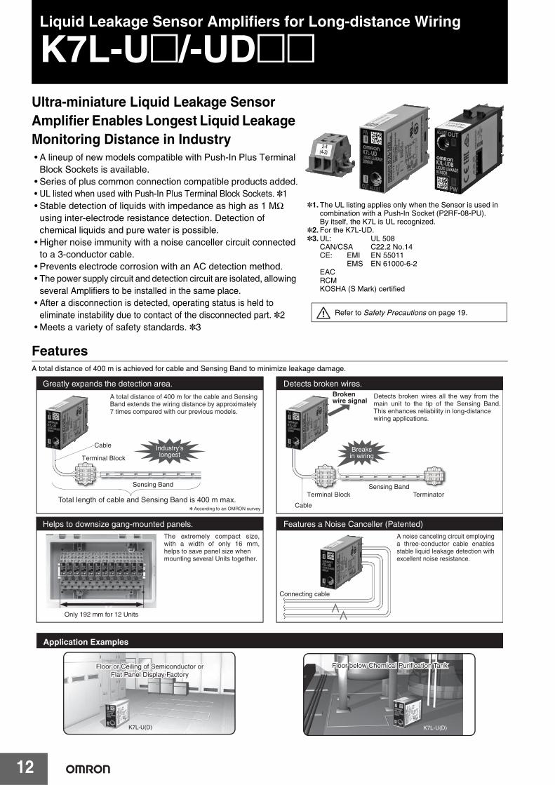
K7L-U@/-UD@@Ultra-miniature Liquid Leakage Sensor Amplifier Enables Longest Liquid Leakage Monitoring Distance in Industry• A lineup of new models compatible with Push-In Plus Terminal
Block Sockets is available.• Series of plus common connection compatible products added.• UL listed when used with Push-In Plus Terminal Block Sockets. *1• Stable detection of liquids with impedance as high as 1 MΩ
using inter-electrode resistance detection. Detection of chemical liquids and pure water is possible.
• Higher noise immunity with a noise canceller circuit connected to a 3-conductor cable.
• Prevents electrode corrosion with an AC detection method.• The power supply circuit and detection circuit are isolated, allowing
several Amplifiers to be installed in the same place.• After a disconnection is detected, operating status is held to
eliminate instability due to contact of the disconnected part. *2• Meets a variety of safety standards. *3
FeaturesA total distance of 400 m is achieved for cable and Sensing Band to minimize leakage damage.
*1.The UL listing applies only when the Sensor is used in combination with a Push-In Socket (P2RF-08-PU).By itself, the K7L is UL recognized.
*2.For the K7L-UD.*3.UL: UL 508
CAN/CSA C22.2 No.14CE: EMI EN 55011
EMS EN 61000-6-2EACRCMKOSHA (S Mark) certified
Refer to Safety Precautions on page 19.
23
4
23
4
Cable
Terminal Block
Terminal Block Terminator
Connecting cable
Total length of cable and Sensing Band is 400 m max.Cable
Industry'slongest
Sensing Band
Breaksin wiring
Brokenwire signal
Only 192 mm for 12 Units
* According to an OMRON survey
2-4
(4
-2
)23
4
23
4
Sensing Band
Greatly expands the detection area. Detects broken wires.
A total distance of 400 m for the cable and SensingBand extends the wiring distance by approximately7 times compared with our previous models.
Detects broken wires all the way from the main unit to the tip of the Sensing Band. This enhances reliability in long-distancewiring applications.
Helps to downsize gang-mounted panels. Features a Noise Canceller (Patented)The extremely compact size, with a width of only 16 mm, helps to save panel size whenmounting several Units together.
A noise canceling circuit employing a three-conductor cable enables stable liquid leakage detection with excellent noise resistance.
Application Examples
Floor below Chemical Purification TankFloor below Chemical Purification TankFloor below Chemical Purification TankFloor or Ceiling of Semiconductor orFloor or Ceiling of Semiconductor orFlat Panel Display FactoryFlat Panel Display Factory
Floor or Ceiling of Semiconductor orFlat Panel Display Factory
K7L-U(D)K7L-U(D)
K7L-U@/-UD@@
13
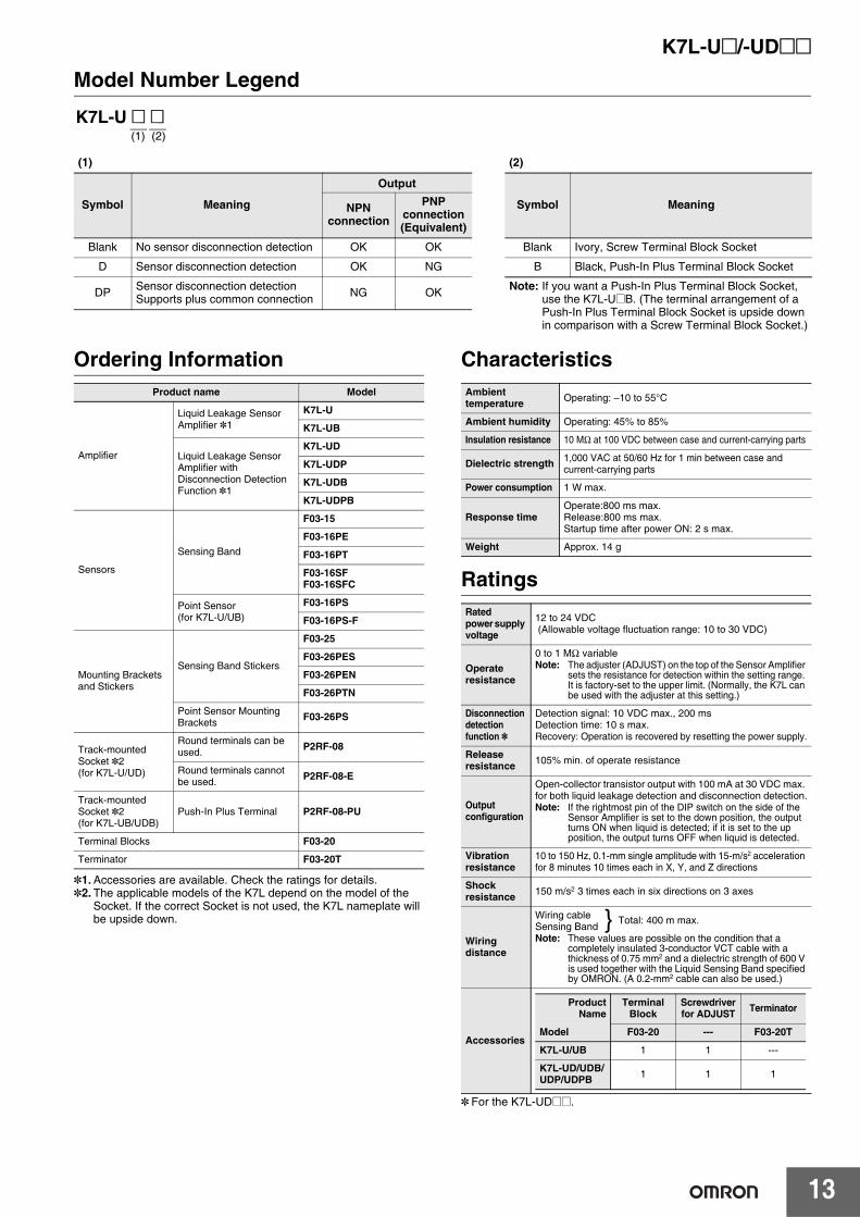
Model Number Legend
Ordering Information
*1.Accessories are available. Check the ratings for details.*2.The applicable models of the K7L depend on the model of the
Socket. If the correct Socket is not used, the K7L nameplate will be upside down.
Characteristics
Ratings
* For the K7L-UD@@.
K7L-U @ @(1) (2)
(1) (2)
Symbol Meaning
Output
Symbol MeaningNPN connection
PNP connection (Equivalent)
Blank No sensor disconnection detection OK OK Blank Ivory, Screw Terminal Block Socket
D Sensor disconnection detection OK NG B Black, Push-In Plus Terminal Block Socket
DP Sensor disconnection detectionSupports plus common connection NG OK Note: If you want a Push-In Plus Terminal Block Socket,
use the K7L-U@B. (The terminal arrangement of a Push-In Plus Terminal Block Socket is upside down in comparison with a Screw Terminal Block Socket.)
Product name Model
Amplifier
Liquid Leakage Sensor Amplifier *1
K7L-U
K7L-UB
Liquid Leakage Sensor Amplifier with Disconnection Detection Function *1
K7L-UD
K7L-UDP
K7L-UDB
K7L-UDPB
Sensors
Sensing Band
F03-15
F03-16PE
F03-16PT
F03-16SFF03-16SFC
Point Sensor(for K7L-U/UB)
F03-16PS
F03-16PS-F
Mounting Brackets and Stickers
Sensing Band Stickers
F03-25
F03-26PES
F03-26PEN
F03-26PTN
Point Sensor Mounting Brackets F03-26PS
Track-mounted Socket *2(for K7L-U/UD)
Round terminals can be used. P2RF-08
Round terminals cannot be used. P2RF-08-E
Track-mounted Socket *2(for K7L-UB/UDB)
Push-In Plus Terminal P2RF-08-PU
Terminal Blocks F03-20
Terminator F03-20T
Ambient temperature Operating: –10 to 55°C
Ambient humidity Operating: 45% to 85%
Insulation resistance 10 MΩ at 100 VDC between case and current-carrying parts
Dielectric strength 1,000 VAC at 50/60 Hz for 1 min between case and current-carrying parts
Power consumption 1 W max.
Response timeOperate:800 ms max. Release:800 ms max.Startup time after power ON: 2 s max.
Weight Approx. 14 g
Rated power supply voltage
12 to 24 VDC (Allowable voltage fluctuation range: 10 to 30 VDC)
Operate resistance
0 to 1 MΩ variableNote: The adjuster (ADJUST) on the top of the Sensor Amplifier
sets the resistance for detection within the setting range. It is factory-set to the upper limit. (Normally, the K7L can be used with the adjuster at this setting.)
Disconnection detection function *
Detection signal: 10 VDC max., 200 msDetection time: 10 s max.Recovery: Operation is recovered by resetting the power supply.
Release resistance 105% min. of operate resistance
Output configuration
Open-collector transistor output with 100 mA at 30 VDC max. for both liquid leakage detection and disconnection detection.Note: If the rightmost pin of the DIP switch on the side of the
Sensor Amplifier is set to the down position, the output turns ON when liquid is detected; if it is set to the up position, the output turns OFF when liquid is detected.
Vibration resistance
10 to 150 Hz, 0.1-mm single amplitude with 15-m/s2 acceleration for 8 minutes 10 times each in X, Y, and Z directions
Shock resistance 150 m/s2 3 times each in six directions on 3 axes
Wiring distance
Wiring cableSensing BandNote: These values are possible on the condition that a
completely insulated 3-conductor VCT cable with a thickness of 0.75 mm2 and a dielectric strength of 600 V is used together with the Liquid Sensing Band specified by OMRON. (A 0.2-mm2 cable can also be used.)
Accessories
} Total: 400 m max.
ProductName
Terminal Block
Screwdriver for ADJUST Terminator
Model F03-20 --- F03-20T
K7L-U/UB 1 1 ---
K7L-UD/UDB/UDP/UDPB 1 1 1
K7L-U@/-UD@@
14
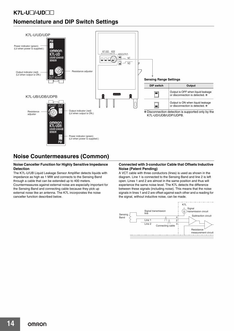
Nomenclature and DIP Switch Settings
Noise Countermeasures (Common)Noise Canceller Function for Highly Sensitive Impedance DetectionThe K7L-U/UB Liquid Leakage Sensor Amplifier detects liquids with impedance as high as 1 MW and connects to the Sensing Band through a cable that can be extended up to 400 meters. Countermeasures against external noise are especially important for the Sensing Band and connecting cable because they pick up external noise like an antenna. The K7L incorporates the noise canceller function described below.
Connected with 3-conductor Cable that Offsets Inductive Noise (Patent Pending)A VCT cable with three conductors (lines) is used as shown in the diagram. Line 1 is connected to the Sensing Band and line 2 is left open. Lines 1 and 2 are almost in the same position and thus will experience the same noise level. The K7L detects the difference between these signals (including noise). This means that the noise signals in lines 1 and 2 are offset against each other and a reading for the signal, without inductive noise, can be made.
Power indicator (green) (Lit when power is supplied.)
Output indicator (red) (Lit when output is ON.)
Resistance adjuster
Power indicator (green) (Lit when power is supplied.)
Output indicator (red) (Lit when output is ON.)
Resistance adjuster
K7L-U/UD/UDP
K7L-UB/UDB/UDPB
Sensing Range Settings
* Disconnection detection is supported only by the K7L-UD/UDB/UDP/UDPB.
DIP switch Output
Output is OFF when liquid leakage or disconnection is detected. *
Output is ON when liquid leakage or disconnection is detected. *
42
3
Sensing Band
Signal transmission line
Line 1
Line 2Connecting cable
Signal transmission circuit
Subtraction circuit
Resistance measurement circuit
K7L
K7L-U@/-UD@@
15
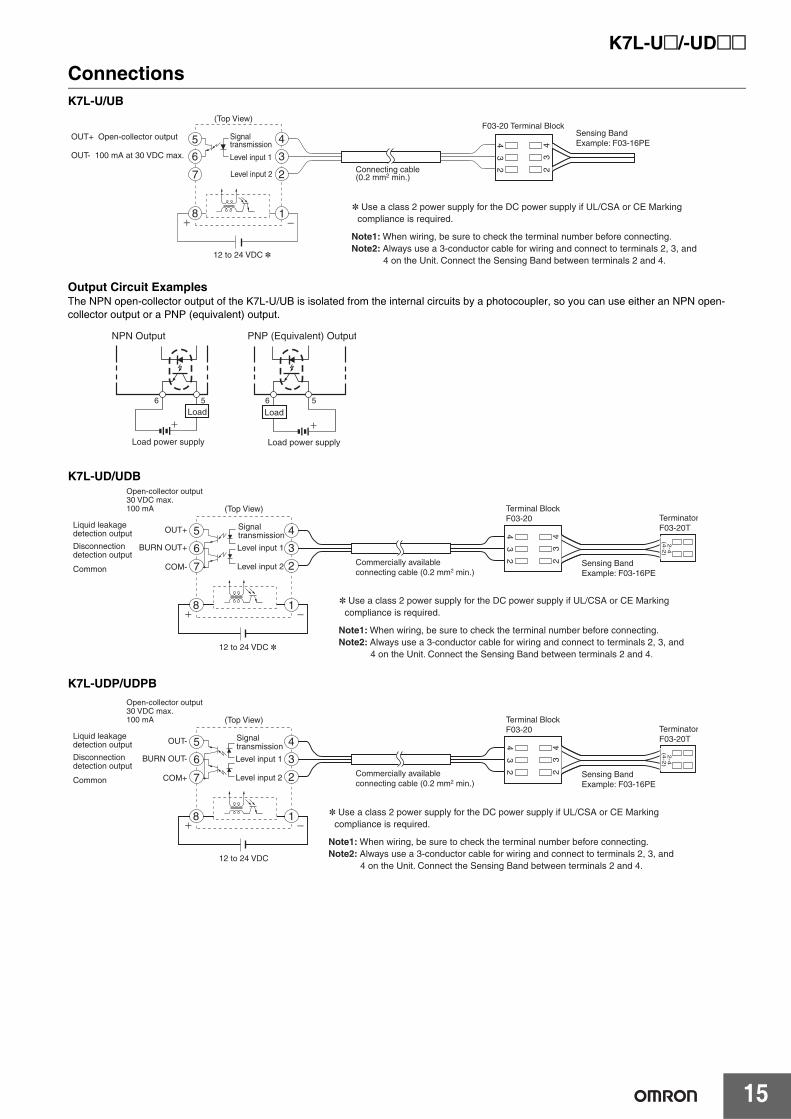
ConnectionsK7L-U/UB
Output Circuit ExamplesThe NPN open-collector output of the K7L-U/UB is isolated from the internal circuits by a photocoupler, so you can use either an NPN open-collector output or a PNP (equivalent) output.
K7L-UD/UDB
K7L-UDP/UDPB
23
442
3
5
6
7
8 1
4
3
2
Signal transmission
Level input 1
Level input 2
12 to 24 VDC *
Connecting cable(0.2 mm2 min.)
F03-20 Terminal BlockSensing BandExample: F03-16PE
OUT+ Open-collector output
OUT- 100 mA at 30 VDC max.
(Top View)
* Use a class 2 power supply for the DC power supply if UL/CSA or CE Marking compliance is required.
Note1: When wiring, be sure to check the terminal number before connecting.Note2: Always use a 3-conductor cable for wiring and connect to terminals 2, 3, and
4 on the Unit. Connect the Sensing Band between terminals 2 and 4.
6 5 6 5
NPN Output PNP (Equivalent) Output
Load
Load power supply Load power supply
Load
8
23
442
3
5
6
7
4
3
2
1
(4-2
)2
-4
* Use a class 2 power supply for the DC power supply if UL/CSA or CE Marking compliance is required.
Note1: When wiring, be sure to check the terminal number before connecting.Note2: Always use a 3-conductor cable for wiring and connect to terminals 2, 3, and
4 on the Unit. Connect the Sensing Band between terminals 2 and 4.
(Top View)
Signal transmission
Level input 1
Level input 2
Liquid leakage detection output
Disconnection detection output
Common
OUT+
BURN OUT+
COM-
12 to 24 VDC *
Commercially available connecting cable (0.2 mm2 min.)
Terminal BlockF03-20
Sensing BandExample: F03-16PE
TerminatorF03-20T
Open-collector output30 VDC max.100 mA
8
23
442
3
5
6
7
4
3
2
1
(4-2
)2
-4
* Use a class 2 power supply for the DC power supply if UL/CSA or CE Marking compliance is required.
Note1: When wiring, be sure to check the terminal number before connecting.Note2: Always use a 3-conductor cable for wiring and connect to terminals 2, 3, and
4 on the Unit. Connect the Sensing Band between terminals 2 and 4.
(Top View)
Signal transmission
Level input 1
Level input 2
Liquid leakage detection output
Disconnection detection output
Common
OUT-
BURN OUT-
COM+
12 to 24 VDC
Commercially available connecting cable (0.2 mm2 min.)
Terminal BlockF03-20
Sensing BandExample: F03-16PE
TerminatorF03-20T
Open-collector output30 VDC max.100 mA
K7L-U@/-UD@@
16
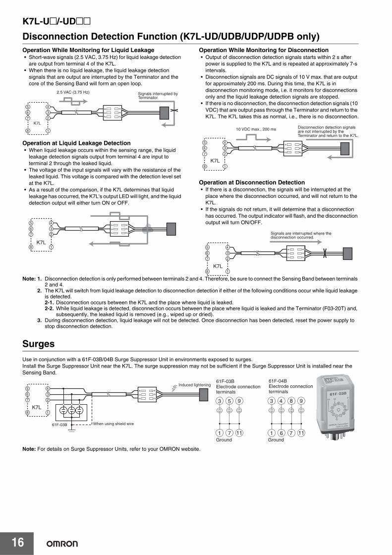
Disconnection Detection Function (K7L-UD/UDB/UDP/UDPB only)Operation While Monitoring for Liquid Leakage• Short-wave signals (2.5 VAC, 3.75 Hz) for liquid leakage detection
are output from terminal 4 of the K7L.• When there is no liquid leakage, the liquid leakage detection
signals that are output are interrupted by the Terminator and the core of the Sensing Band will form an open loop.
Operation at Liquid Leakage Detection• When liquid leakage occurs within the sensing range, the liquid
leakage detection signals output from terminal 4 are input to terminal 2 through the leaked liquid.
• The voltage of the input signals will vary with the resistance of the leaked liquid. This voltage is compared with the detection level set at the K7L.
• As a result of the comparison, if the K7L determines that liquid leakage has occurred, the K7L's output LED will light, and the liquid detection output will either turn ON or OFF.
Operation While Monitoring for Disconnection• Output of disconnection detection signals starts within 2 s after
power is supplied to the K7L and is repeated at approximately 7-s intervals.
• Disconnection signals are DC signals of 10 V max. that are output for approximately 200 ms. During this time, the K7L is in disconnection monitoring mode, i.e. it monitors for disconnections only and the liquid leakage detection signals are stopped.
• If there is no disconnection, the disconnection detection signals (10 VDC) that are output pass through the Terminator and return to the K7L. The K7L takes this as normal, i.e., there is no disconnection.
Operation at Disconnection Detection• If there is a disconnection, the signals will be interrupted at the
place where the disconnection occurred, and will not return to the K7L.
• If the signals do not return, it will determine that a disconnection has occurred. The output indicator will flash, and the disconnection output will turn ON/OFF.
Note: 1. Disconnection detection is only performed between terminals 2 and 4. Therefore, be sure to connect the Sensing Band between terminals 2 and 4.
2. The K7L will switch from liquid leakage detection to disconnection detection if either of the following conditions occur while liquid leakage is detected.2-1. Disconnection occurs between the K7L and the place where liquid is leaked.2-2. While liquid leakage is detected, disconnection occurs between the place where liquid is leaked and the Terminator (F03-20T) and,
subsequently, the leaked liquid is removed (e.g., wiped up or dried).3. During disconnection detection, liquid leakage will not be detected. Once disconnection has been detected, reset the power supply to
stop disconnection detection.
Surges
23
442
3
5
6
7
8
4
3
2
1
K7L
2.5 VAC (3.75 Hz) Signals interrupted by Terminator.
23
442
3
5
6
7
8
4
3
2
1K7L
23
442
3
5
6
7
8
4
3
2
1
K7L
10 VDC max., 200 ms Disconnection detection signals are not interrupted by the Terminator and return to the K7L.
23
442
3
5
6
7
8
4
3
2
1K7L
Signals are interrupted where the disconnection occurred.
23
442
3
5
6
7
8
4
3
2
1K7L
When using shield wire61F-03B
Induced lightening
953
1171
43
61
98
117Ground Ground
61F-03BElectrode connection terminals
61F-04BElectrode connection terminals
Use in conjunction with a 61F-03B/04B Surge Suppressor Unit in environments exposed to surges.Install the Surge Suppressor Unit near the K7L. The surge suppression may not be sufficient if the Surge Suppressor Unit is installed near the Sensing Band.
Note: For details on Surge Suppressor Units, refer to your OMRON website.
K7L-U@/-UD@@
17
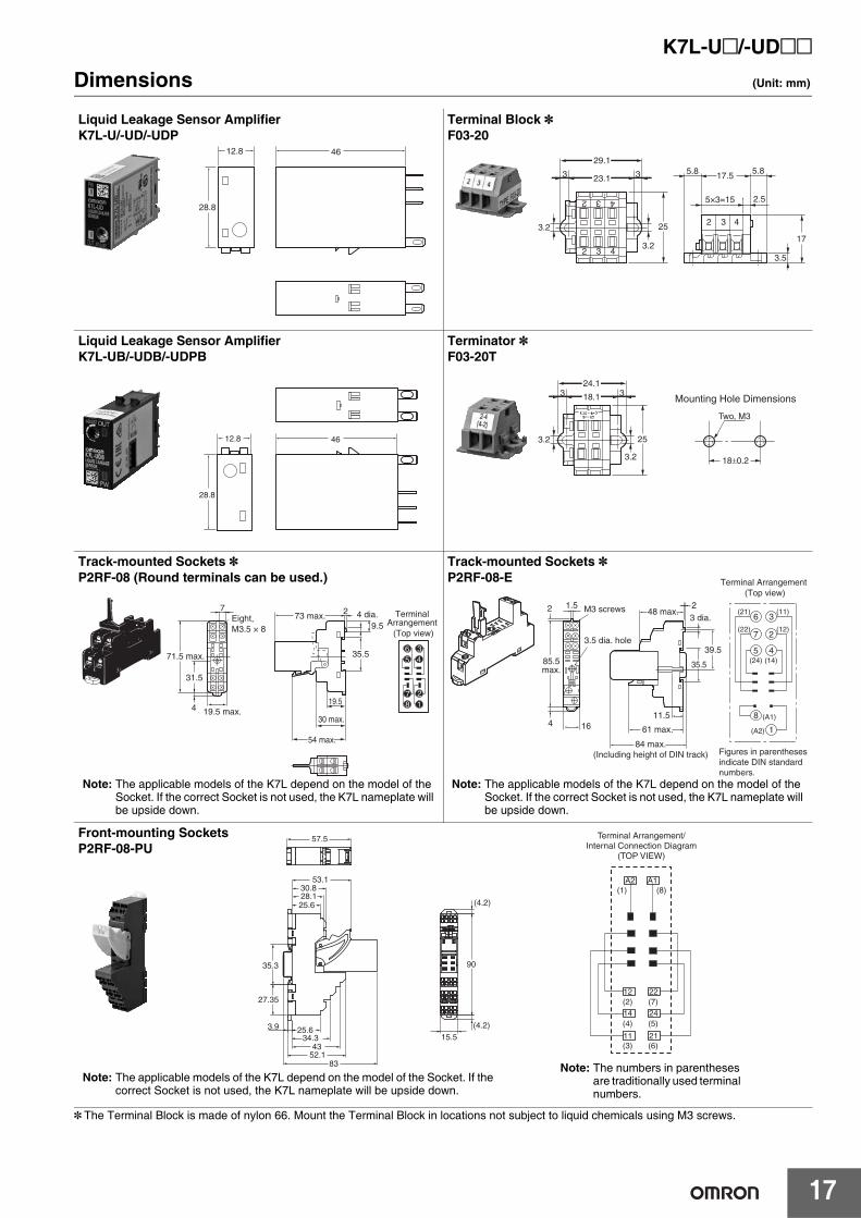
Dimensions (Unit: mm)
* The Terminal Block is made of nylon 66. Mount the Terminal Block in locations not subject to liquid chemicals using M3 screws.
12.8
28.8
46
Liquid Leakage Sensor AmplifierK7L-U/-UD/-UDP
2 3 4
2 3
29.1
23.13 3
4
3.2
3.2
25 2 3 4
5×3=15 2.5
3.5
17.55.8
17
5.8
Terminal Block *F03-20
Liquid Leakage Sensor AmplifierK7L-UB/-UDB/-UDPB
12.8
28.8
46 3.2
3.2
25
2-4(4-2)
24.1
18.13 3
18±0.2
Two, M3
Mounting Hole Dimensions
Terminator *F03-20T
2
9.5
35.5
19.5
7
31.5
4
21
78
34
65
(Top view)
TerminalArrangement
4 dia.
30 max.
54 max.
Eight, M3.5 × 8
19.5 max.
71.5 max.
73 max.
Track-mounted Sockets *P2RF-08 (Round terminals can be used.)
Note: The applicable models of the K7L depend on the model of the Socket. If the correct Socket is not used, the K7L nameplate will be upside down.
164
2 1.5
1
8
4
2
3
5
7
6
(A2)
(A1)
(24) (14)
(12)(22)
(11)(21)
11.5
35.5
39.5
2
85.5max.
3.5 dia. hole
M3 screws
Figures in parentheses indicate DIN standard numbers.
61 max.
3 dia.48 max.
84 max.(Including height of DIN track)
(Top view)Terminal Arrangement
Track-mounted Sockets *P2RF-08-E
Note: The applicable models of the K7L depend on the model of the Socket. If the correct Socket is not used, the K7L nameplate will be upside down.
83
Terminal Arrangement/Internal Connection Diagram
(TOP VIEW)
14
22
24
21
12
11
A1A2(8)(1)
(2) (7)
(4) (5)
(3) (6)15.5
90
(4.2)
(4.2)
57.5
27.35
35.3
53.1
28.125.6
30.8
4334.3
25.6
52.1
3.9
Front-mounting SocketsP2RF-08-PU
Note: The applicable models of the K7L depend on the model of the Socket. If the correct Socket is not used, the K7L nameplate will be upside down.
Note: The numbers in parentheses are traditionally used terminal numbers.
K7L-U@/-UD@@
18
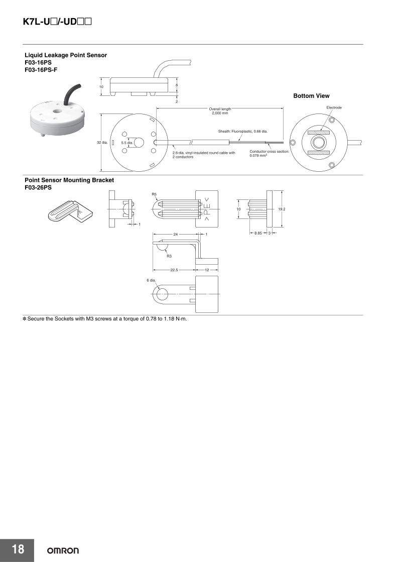
* Secure the Sockets with M3 screws at a torque of 0.78 to 1.18 N·m.
10 8
2
Conductor cross section: 0.079 mm2
Sheath: Fluoroplastic, 0.66 dia.
Electrode
5.5 dia.
Overall length2,000 mm
2.6-dia. vinyl-insulated round cable with2 conductors
32 dia.
Liquid Leakage Point SensorF03-16PSF03-16PS-F
Bottom View
19.2
38.85
10
1222.5
6 dia.
R3
24 1
R5
1
Point Sensor Mounting BracketF03-26PS
K7L-U@/-UD@@
19
Safety PrecautionsWarning Indications
Meaning of Product Safety Symbols
This product cannot be used as a detection device for protecting human life.
Observe the following points to ensure safe operation.1. Be sure to use a power supply voltage within the specified range.
Not doing so may result in burning or malfunction.2. Do not use the product in locations subject to flammable gases or
combustible objects. Doing so may result in fire.3. Insert the connection points into Sockets until the connection is
locked securely. Not doing so may result in burning or malfunction.4. Do not short-circuit loads connected to output terminals. Doing so
may result in burning.5. Be sure to connect the power supply with the correct polarity. Not
doing so may result in malfunction.6. Use a control power supply, an input power supply, and a line
power supply with suitable specifications.To use under the UL Listing specifications, use AWG20 to AWG16 solid or stranded copper wires for the line power supply.Recommended cable: 0.75 mm2 600-V VCT 3-core, completely
insulated
InstallationAttach to a panel of thickness 1 to 5 mm.Do not install in the following locations.1. Locations subject to shock or vibration2. Locations where the temperature or humidity lies outside the
specified range, or where condensation is likely to occur (To detect liquids with high impedances, do not use in locations with high humidity.)
3. Locations subject to dust4. Locations subject to corrosive gases (particularly sulfide and
ammonia gases)5. Outdoors or locations subject to direct sunlight6. Near devices that generate strong high-frequency noise (e.g.,
high-frequency welding devices etc.)
You must allow sufficient leeway in ratings and performance, and provide proper fail-safe or other safety measures when using these products in any of the following applications. Be sure also to consult with your OMRON representative before actually attempting any of these applications.1. Applications under conditions or environments not specified in
user documentation2. Applications for nuclear control systems, railroad systems,
aviation systems, vehicles, combustion systems, medical equipment, amusement machines, or safety equipment
3. Applications that may have a serious influence on lives and property and thus require particularly attention to safety
WARNING
Indicates a potentially hazardous situation which, if not avoided, will result in minor or moderate injury, or may result in serious injury or death. Additionally there may be significant property damage.
Precautions for Safe Use
Supplementary comments on what to do or avoid doing, to use the product safely.
Precautions for Correct Use
Supplementary comments on what to do or avoid doing, to prevent failure to operate, malfunction, or undesirable effects on product performance.
Used for general prohibitions for which is no specific symbol.
WARNING
Precautions for Safe Use
Precautions for Correct Use
Application Precautions
K7L-U@/-UD@@
20
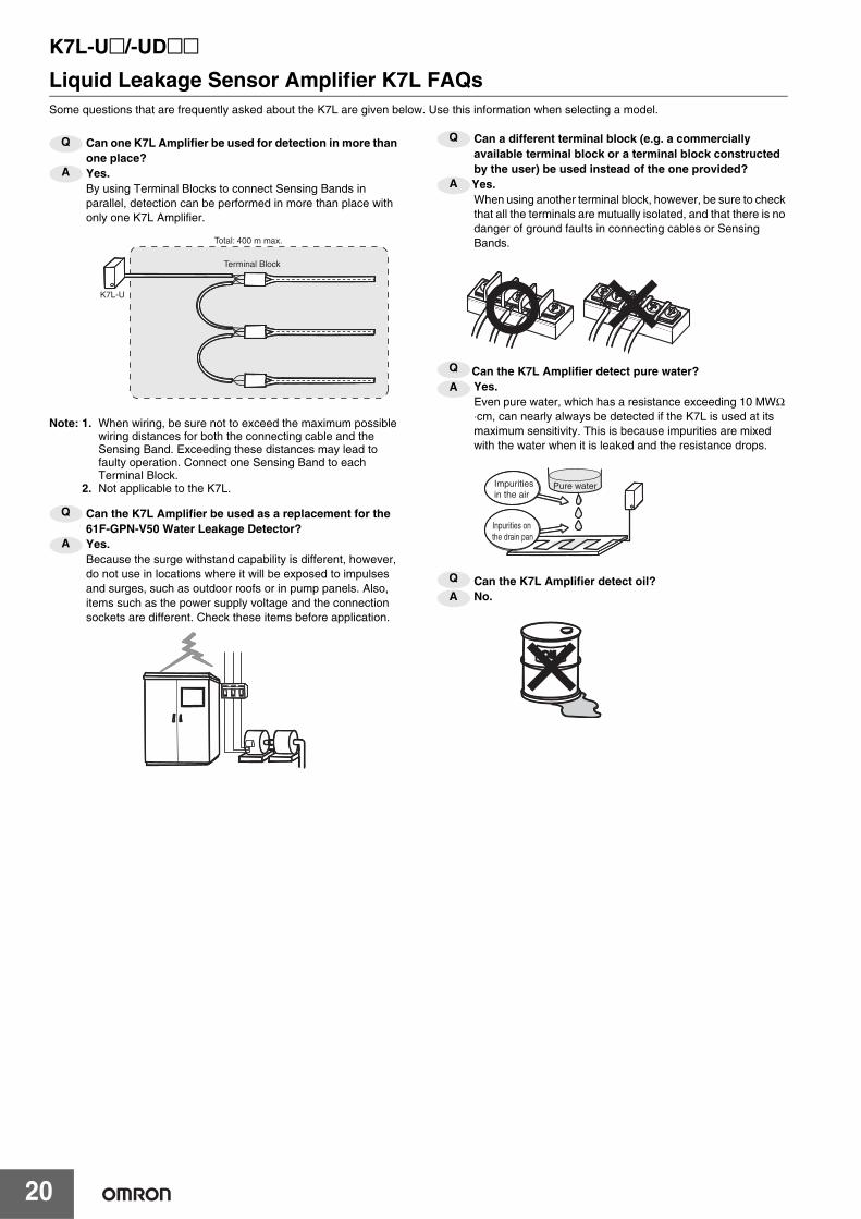
Liquid Leakage Sensor Amplifier K7L FAQsSome questions that are frequently asked about the K7L are given below. Use this information when selecting a model.
Can one K7L Amplifier be used for detection in more than one place?Yes.By using Terminal Blocks to connect Sensing Bands in parallel, detection can be performed in more than place with only one K7L Amplifier.
Note: 1. When wiring, be sure not to exceed the maximum possible wiring distances for both the connecting cable and the Sensing Band. Exceeding these distances may lead to faulty operation. Connect one Sensing Band to each Terminal Block.
2. Not applicable to the K7L.
Can the K7L Amplifier be used as a replacement for the 61F-GPN-V50 Water Leakage Detector?Yes.Because the surge withstand capability is different, however, do not use in locations where it will be exposed to impulses and surges, such as outdoor roofs or in pump panels. Also, items such as the power supply voltage and the connection sockets are different. Check these items before application.
Can a different terminal block (e.g. a commercially available terminal block or a terminal block constructed by the user) be used instead of the one provided?Yes.When using another terminal block, however, be sure to check that all the terminals are mutually isolated, and that there is no danger of ground faults in connecting cables or Sensing Bands.
Can the K7L Amplifier detect pure water?Yes.Even pure water, which has a resistance exceeding 10 MWΩ ⋅cm, can nearly always be detected if the K7L is used at its maximum sensitivity. This is because impurities are mixed with the water when it is leaked and the resistance drops.
Can the K7L Amplifier detect oil?No.
Q
A
Terminal Block
Total: 400 m max.
K7L-U
Q
A
Q
A
Q
A
Pure waterImpurities in the air
Inpurities on the drain pan
Q
A
F03-16PE/-16PT/-15/-16PS
21
Sensing Band/Point Sensor
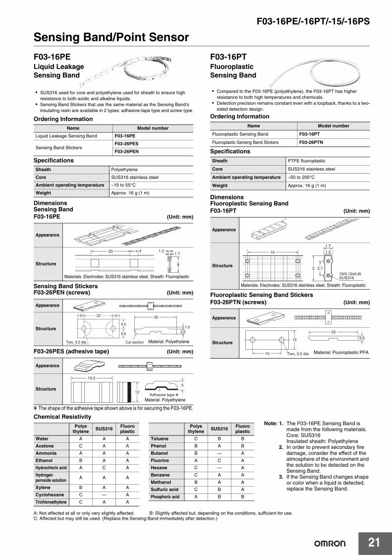
• SUS316 used for core and polyethylene used for sheath to ensure high resistance to both acidic and alkaline liquids.
• Sensing Band Stickers that use the same material as the Sensing Band's insulating resin are available in 2 types: adhesive-tape type and screw type.
Ordering Information
Specifications
DimensionsSensing BandF03-16PE (Unit: mm)
Sensing Band StickersF03-26PEN (screws) (Unit: mm)
F03-26PES (adhesive tape) (Unit: mm)
* The shape of the adhesive tape shown above is for securing the F03-16PE.
• Compared to the F03-16PE (polyethylene), the F03-16PT has higher resistance to both high temperatures and chemicals.
• Detection precision remains constant even with a loopback, thanks to a two-sided detection design.
Ordering Information
Specifications
DimensionsFluoroplastic Sensing BandF03-16PT (Unit: mm)
Fluoroplastic Sensing Band StickersF03-26PTN (screws) (Unit: mm)
Chemical Resistivity
Name Model number
Liquid Leakage Sensing Band F03-16PE
Sensing Band StickersF03-26PES
F03-26PEN
Sheath Polyethylene
Core SUS316 stainless steel
Ambient operating temperature –15 to 55°C
Weight Approx. 16 g (1 m)
Appearance
Structure
Appearance
Structure
Appearance
Structure
F03-16PELiquid Leakage Sensing Band
20 4 1.21.7
8
Materials: Electrodes: SUS316 stainless steel, Sheath: Fluoroplastic
22
Two, 3.5 dia. Cut section
5 5
6.5
6.5
3.01.0
32
Material: Polyethylene
19.2
12Adhesive tape *
5
Material: Polyethylene
Name Model number
Fluoroplastic Sensing Band F03-16PT
Fluoroplastic Sensing Band Stickers F03-26PTN
Sheath PTFE fluoroplastic
Core SUS316 stainless steel
Ambient operating temperature –50 to 200°C
Weight Approx. 16 g (1 m)
Appearance
Structure
Appearance
Structure
F03-16PTFluoroplastic Sensing Band
1.2
1.7
2.75
10
19/0.12x0.6tSUS316
Materials: Electrodes: SUS316 stainless steel, Sheath: Fluoroplastic
25
15 Two, 3.5 dia.
12 3.0
Material: Fluoroplastic PFA
Note: 1. The F03-16PE Sensing Band is made from the following materials.Core: SUS316Insulated sheath: Polyethylene
2. In order to prevent secondary fire damage, consider the effect of the atmosphere of the environment and the solution to be detected on the Sensing Band.
3. If the Sensing Band changes shape or color when a liquid is detected, replace the Sensing Band.
A: Not affected at all or only very slightly affected. B: Slightly affected but, depending on the conditions, sufficient for use. C: Affected but may still be used. (Replace the Sensing Band immediately after detection.)
Polye thylene SUS316 Fluoro
plastic
Water A A A
Acetone C A A
Ammonia A A A
Ethanol B A A
Hydrochloric acid A C A
Hydrogen peroxide solution A A A
Xylene B A A
Cyclohexane C --- A
Trichloroethylene C A A
Polyethylene SUS316 Fluoro
plastic
Toluene C B B
Phenol B A B
Butanol B --- A
Fluorine A C A
Hexane C --- A
Benzene C A A
Methanol B A A
Sulfuric acid C B A
Phosphoric acid A B B
F03-16PE/-16PT/-15/-16PS
22
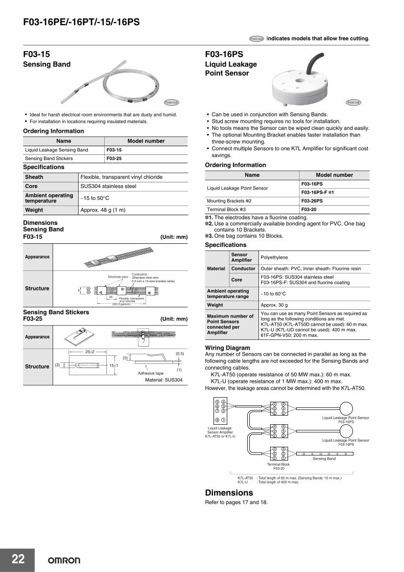
• Ideal for harsh electrical room environments that are dusty and humid.• For installation in locations requiring insulated materials.
Ordering Information
Specifications
DimensionsSensing BandF03-15 (Unit: mm)
Sensing Band StickersF03-25 (Unit: mm)
• Can be used in conjunction with Sensing Bands.• Stud screw mounting requires no tools for installation.• No tools means the Sensor can be wiped clean quickly and easily.• The optional Mounting Bracket enables faster installation than
three-screw mounting.• Connect multiple Sensors to one K7L Amplifier for significant cost
savings.
Ordering Information
*1. The electrodes have a fluorine coating.*2.Use a commercially available bonding agent for PVC. One bag
contains 10 Brackets.*3.One bag contains 10 Blocks.
Specifications
Wiring DiagramAny number of Sensors can be connected in parallel as long as the following cable lengths are not exceeded for the Sensing Bands and connecting cables.
K7L-AT50 (operate resistance of 50 MW max.): 60 m max.K7L-U (operate resistance of 1 MW max.): 400 m max.
However, the leakage areas cannot be determined with the K7L-AT50.
DimensionsRefer to pages 17 and 18.
Indicates models that allow free cutting.
Name Model number
Liquid Leakage Sensing Band F03-15
Sensing Band Stickers F03-25
Sheath Flexible, transparent vinyl chloride
Core SUS304 stainless steel
Ambient operating temperature −15 to 50°C
Weight Approx. 48 g (1 m)
Appearance
Structure
Appearance
Structure
F03-15Sensing Band
8
25
Electrode pairs
Flexible, transparentvinyl chloride
Conductors
333 (3 pairs/m)
(Stainless steel wire0.3 mm x 12-wire braided cable)
Adhesive tape
25±2
15±1(3)
(5)(0.5)
(1)
Material: SUS304
Name Model number
Liquid Leakage Point SensorF03-16PS
F03-16PS-F *1
Mounting Brackets *2 F03-26PS
Terminal Block *3 F03-20
Material
Sensor Amplifier Polyethylene
Conductor Outer sheath: PVC, Inner sheath: Fluorine resin
Core F03-16PS: SUS304 stainless steelF03-16PS-F: SUS304 and fluorine coating
Ambient operating temperature range −10 to 60°C
Weight Approx. 30 g
Maximum number of Point Sensors connected per Amplifier
You can use as many Point Sensors as required as long as the following conditions are met.K7L-AT50 (K7L-AT50D cannot be used): 60 m max.K7L-U (K7L-UD cannot be used): 400 m max.61F-GPN-V50: 200 m max.
F03-16PSLiquid Leakage Point Sensor
34
567
8
432
1
234
2
34
234
2
34
234
2
Liquid Leakage Sensor Amplifier
K7L-AT50 or K7L-U
Terminal Block F03-20
Liquid Leakage Point Sensor F03-16PS
Liquid Leakage Point Sensor F03-16PS
Sensing Band
K7L-AT50 : Total length of 60 m max. (Sensing Bands: 10 m max.)K7L-U : Total length of 400 m max.
F03-16PE/-16PT/-15/-16PS
23
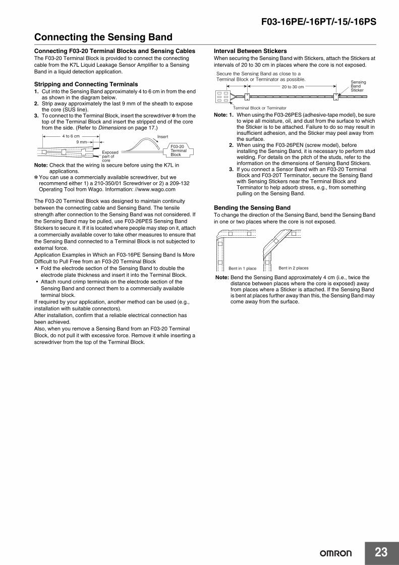
Connecting the Sensing BandConnecting F03-20 Terminal Blocks and Sensing CablesThe F03-20 Terminal Block is provided to connect the connecting cable from the K7L Liquid Leakage Sensor Amplifier to a Sensing Band in a liquid detection application.
Stripping and Connecting Terminals1. Cut into the Sensing Band approximately 4 to 6 cm in from the end
as shown in the diagram below.2. Strip away approximately the last 9 mm of the sheath to expose
the core (SUS line).3. To connect to the Terminal Block, insert the screwdriver * from the
top of the Terminal Block and insert the stripped end of the core from the side. (Refer to Dimensions on page 17.)
Note: Check that the wiring is secure before using the K7L in applications.
* You can use a commercially available screwdriver, but we recommend either 1) a 210-350/01 Screwdriver or 2) a 209-132 Operating Tool from Wago. Information: //www.wago.com
The F03-20 Terminal Block was designed to maintain continuity between the connecting cable and Sensing Band. The tensile strength after connection to the Sensing Band was not considered. If the Sensing Band may be pulled, use F03-26PES Sensing Band Stickers to secure it. If it is located where people may step on it, attach a commercially available cover to take other measures to ensure that the Sensing Band connected to a Terminal Block is not subjected to external force.Application Examples in Which an F03-16PE Sensing Band Is More Difficult to Pull Free from an F03-20 Terminal Block• Fold the electrode section of the Sensing Band to double the
electrode plate thickness and insert it into the Terminal Block.• Attach round crimp terminals on the electrode section of the
Sensing Band and connect them to a commercially available terminal block.
If required by your application, another method can be used (e.g., installation with suitable connectors).After installation, confirm that a reliable electrical connection has been achieved.Also, when you remove a Sensing Band from an F03-20 Terminal Block, do not pull it with excessive force. Remove it while inserting a screwdriver from the top of the Terminal Block.
Interval Between StickersWhen securing the Sensing Band with Stickers, attach the Stickers at intervals of 20 to 30 cm in places where the core is not exposed.
Note: 1. When using the F03-26PES (adhesive-tape model), be sure to wipe all moisture, oil, and dust from the surface to which the Sticker is to be attached. Failure to do so may result in insufficient adhesion, and the Sticker may peel away from the surface.
2. When using the F03-26PEN (screw model), before installing the Sensing Band, it is necessary to perform stud welding. For details on the pitch of the studs, refer to the information on the dimensions of Sensing Band Stickers.
3. If you connect a Sensor Band with an F03-20 Terminal Block and F03-20T Terminator, secure the Sensing Band with Sensing Stickers near the Terminal Block and Terminator to help adsorb stress, e.g., from something pulling on the Sensing Band.
Bending the Sensing BandTo change the direction of the Sensing Band, bend the Sensing Band in one or two places where the core is not exposed.
4 to 6 cm9 mm
Exposed part of core
Insert
F03-20 Terminal Block
Secure the Sensing Band as close to a Terminal Block or Terminator as possible.
Terminal Block or Terminator
Sensing Band Sticker
20 to 30 cm
Bent in 2 placesBent in 1 place
Note: Bend the Sensing Band approximately 4 cm (i.e., twice the distance between places where the core is exposed) away from places where a Sticker is attached. If the Sensing Band is bent at places further away than this, the Sensing Band may come away from the surface.

F03-16SF/-16SFC
24
Liquid Leakage Sensing BandF03-16SF/F03-16SFCLiquid Leakage Sensing BandGreater flexibility and superior workability compared with the F03-16PE. The sheath becomes transparent to reveal the red inner sheath if liquid leakage occurs, thereby enabling visual confirmation. After drying, the Sensing Band color will return to white.
Ordering Information
Note: When you select a Sensing Band, confirm the suitability for the detection liquid and the specifications of the Water/Liquid Leakage Sensor.
Specifications
Note: 1. In order to prevent secondary fire damage, consider the effect of the atmosphere of the environment and the solution to be detected on the Sensing Band.
2. If the Sensing Band becomes misshapen, discolored, or otherwise abnormal after detection, replace the Sensing Band.
Dimensions (Unit: mm)Sensing Band Cable Sticker
F03-16SF F03-16SFC (with color indication)
Type
Length
Liquid Leakage Sensing Band (without color indication)
F03-16SF
Liquid Leakage Sensing Band (with color indication)
F03-16SFC
Model Model
5 m F03-16SF-5M F03-16SFC-5M
10 m F03-16SF-10M F03-16SFC-10M
20 m F03-16SF-20M F03-16SFC-20M
30 m F03-16SF-30M F03-16SFC-30M
50 m F03-16SF-50M F03-16SFC-50M
100 m F03-16SF-100M F03-16SFC-100M
Sheath Special plastic fiber braided cable with water-absorbent and water-repellent characteristics
Core Tin-plated, copper-stranded wire 0.75mm2
Ambient operating temperature −15 to 60°C
Weight Approximately 20 g (1 m)
Type
Item
Liquid Leakage Sensing Band
F03-16SF
Liquid Leakage Sensing Band
(with color indication)F03-16SFC
Appearance
Structure
Electrode Internal braiding External braiding
5 mm max.
External braiding (white)
Internal braiding (white)
Electrode
5 mm max.
External braiding (white)
Internal braiding (red) Electrode
Appearance
(3)(1)
(5)(0.5)
25±2
15±2
Adhesive tape *Material: SUS304
Dimensions
F03-25
Terms and Conditions AgreementRead and understand this catalog.
Please read and understand this catalog before purchasing the products. Please consult your OMRON representative if you have any questions or comments.
Warranties.(a) Exclusive Warranty. Omron’s exclusive warranty is that the Products will be free from defects in materials and workmanship
for a period of twelve months from the date of sale by Omron (or such other period expressed in writing by Omron). Omron disclaims all other warranties, express or implied.
(b) Limitations. OMRON MAKES NO WARRANTY OR REPRESENTATION, EXPRESS OR IMPLIED, ABOUT NON-INFRINGEMENT, MERCHANTABILITY OR FITNESS FOR A PARTICULAR PURPOSE OF THE PRODUCTS. BUYER ACKNOWLEDGES THAT IT ALONE HAS DETERMINED THAT THE PRODUCTS WILL SUITABLY MEET THE REQUIREMENTS OF THEIR INTENDED USE.
Omron further disclaims all warranties and responsibility of any type for claims or expenses based on infringement by the Products or otherwise of any intellectual property right. (c) Buyer Remedy. Omron’s sole obligation hereunder shall be, at Omron’s election, to (i) replace (in the form originally shipped with Buyer responsible for labor charges for removal or replacement thereof) the non-complying Product, (ii) repair the non-complying Product, or (iii) repay or credit Buyer an amount equal to the purchase price of the non-complying Product; provided that in no event shall Omron be responsible for warranty, repair, indemnity or any other claims or expenses regarding the Products unless Omron’s analysis confirms that the Products were properly handled, stored, installed and maintained and not subject to contamination, abuse, misuse or inappropriate modification. Return of any Products by Buyer must be approved in writing by Omron before shipment. Omron Companies shall not be liable for the suitability or unsuitability or the results from the use of Products in combination with any electrical or electronic components, circuits, system assemblies or any other materials or substances or environments. Any advice, recommendations or information given orally or in writing, are not to be construed as an amendment or addition to the above warranty.
See http://www.omron.com/global/ or contact your Omron representative for published information.
Limitation on Liability; Etc.OMRON COMPANIES SHALL NOT BE LIABLE FOR SPECIAL, INDIRECT, INCIDENTAL, OR CONSEQUENTIAL DAMAGES, LOSS OF PROFITS OR PRODUCTION OR COMMERCIAL LOSS IN ANY WAY CONNECTED WITH THE PRODUCTS, WHETHER SUCH CLAIM IS BASED IN CONTRACT, WARRANTY, NEGLIGENCE OR STRICT LIABILITY.
Further, in no event shall liability of Omron Companies exceed the individual price of the Product on which liability is asserted.
Suitability of Use.Omron Companies shall not be responsible for conformity with any standards, codes or regulations which apply to the combination of the Product in the Buyer’s application or use of the Product. At Buyer’s request, Omron will provide applicable third party certification documents identifying ratings and limitations of use which apply to the Product. This information by itself is not sufficient for a complete determination of the suitability of the Product in combination with the end product, machine, system, or other application or use. Buyer shall be solely responsible for determining appropriateness of the particular Product with respect to Buyer’s application, product or system. Buyer shall take application responsibility in all cases.
NEVER USE THE PRODUCT FOR AN APPLICATION INVOLVING SERIOUS RISK TO LIFE OR PROPERTY OR IN LARGE QUANTITIES WITHOUT ENSURING THAT THE SYSTEM AS A WHOLE HAS BEEN DESIGNED TO ADDRESS THE RISKS, AND THAT THE OMRON PRODUCT(S) IS PROPERLY RATED AND INSTALLED FOR THE INTENDED USE WITHIN THE OVERALL EQUIPMENT OR SYSTEM.
Programmable Products.Omron Companies shall not be responsible for the user’s programming of a programmable Product, or any consequence thereof.
Performance Data.Data presented in Omron Company websites, catalogs and other materials is provided as a guide for the user in determining suitability and does not constitute a warranty. It may represent the result of Omron’s test conditions, and the user must correlate it to actual application requirements. Actual performance is subject to the Omron’s Warranty and Limitations of Liability.
Change in Specifications.Product specifications and accessories may be changed at any time based on improvements and other reasons. It is our practice to change part numbers when published ratings or features are changed, or when significant construction changes are made. However, some specifications of the Product may be changed without any notice. When in doubt, special part numbers may be assigned to fix or establish key specifications for your application. Please consult with your Omron’s representative at any time to confirm actual specifications of purchased Product.
Errors and Omissions.Information presented by Omron Companies has been checked and is believed to be accurate; however, no responsibility is assumed for clerical, typographical or proofreading errors or omissions.
Authorized Distributor:
In the interest of product improvement, specifications are subject to change without notice.
Cat. No. N211-E1-03 1018(0316)
© OMRON Corporation 2016-2018 All Rights Reserved.
OMRON Corporation Industrial Automation Company
OMRON ELECTRONICS LLC2895 Greenspoint Parkway, Suite 200 Hoffman Estates, IL 60169 U.S.A.Tel: (1) 847-843-7900/Fax: (1) 847-843-7787
Regional HeadquartersOMRON EUROPE B.V.Wegalaan 67-69, 2132 JD HoofddorpThe NetherlandsTel: (31)2356-81-300/Fax: (31)2356-81-388
Contact: www.ia.omron.comKyoto, JAPAN
OMRON ASIA PACIFIC PTE. LTD.No. 438A Alexandra Road # 05-05/08 (Lobby 2), Alexandra Technopark, Singapore 119967Tel: (65) 6835-3011/Fax: (65) 6835-2711
OMRON (CHINA) CO., LTD.Room 2211, Bank of China Tower, 200 Yin Cheng Zhong Road, PuDong New Area, Shanghai, 200120, ChinaTel: (86) 21-5037-2222/Fax: (86) 21-5037-2200