Linear Static Analysis of a Simply-Supported Truss - …Linear Static Analysis of a Simply-Supported...
46
Linear Static Analysis of a Simply-Supported Truss MSC/NASTRAN 101 Exercise Workbook 2-1 WORKSHOP PROBLEM 2 Objectives: ■ Define a set of material properties using the beam library. ■ Perform a static analysis of a truss under 3 separate loading conditions. ■ Review results.
Transcript of Linear Static Analysis of a Simply-Supported Truss - …Linear Static Analysis of a Simply-Supported...

Linear Static Analysis of aSimply-Supported Truss
MSC/NASTRAN 101 Exercise Workbook 2-1
WORKSHOP PROBLEM 2
Objectives:
■ Define a set of material properties using the beam library.
■ Perform a static analysis of a truss under 3 separate loadingconditions.
■ Review results.

2-2 MSC/NASTRAN 101 Exercise Workbook

WORKSHOP 2 Simply-Supported Truss
nee
-d
Model Description:Below is a finite element representation of the truss structure shownon page 2-1. The nodal coordinates provided are defined in theGlobal Cartesian Coordinate System (MSC/NASTRAN Basicsystem).
The roof frame shown in the attached figure consists of eleven woodand steel members. The wood members, have uniform cross sectioproperties and act only as tension and compression members. (Sepage 2-5 for location.) The steel members, are bars that are capablof withstanding tension, compression, shear, and loads in the planeof the frame. (See page 2-5 for location.) The section properties forthe steel members are supplied as problem data. All the steel members are welded end to end, however, the wood members are pinneend to end. The frame is supported by pinned connections in thehorizontal and vertical directions at Grid Point 1 and in the verticaldirection at Grid Point 7. In addition, all Grid Points have fixed outof plane translations and have constrained out of plane rotations.
Hint: DOF 345 for grid 1 thru 7 can be constrained by using thepermanent single point constraint option in the GRID entry.
Grid Coordinates and Element Connectivities
1
2
3
4
5
6
7
1
2 3
456 7
8
9 10 11
X
Y
Z
[0,0,0]
[144,72,0]
[288,144,0]
[192,0,0] [384,0,0]
[432,72,0]
[576,0,0]
MSC/NASTRAN 101 Exercise Workbook 2-3

of
ed
rly0
ta.
Loads and Boundary Conditions
■ Subcase One will be only the gravity load due to the weightboth the wood and steel members.
■ Subcase Two will be the snow drift load and the concentratload. The snow drift load is in the vertical direction and isgiven as a varying running load. The load increases lineawith distance along the beam, from 0 at Grid Point 4 to 10lbs/in. at Grid Point 1.
■ Subcase Three will be the temperature load which iscalculated as the temperature averages and applied at thejoints. The joint temperatures are supplied as problem daThe stress-free reference temperature is 72.0 degrees F.
545.00
32.00
60.00
66.00
60.00
100.0
80.00
X
Y
Z
Snow Drift100 pounds/inchmaximum
Interior Temperature60 deg. F.
Concentrated Load2000 poundsapplied 36 inches from Grid Point 3
Ambient Temperature 100 deg. F.
Ambient Temperature 32 deg. F.
345 345
345
345
12345
345
2345
2-4 MSC/NASTRAN 101 Exercise Workbook

WORKSHOP 2 Simply-Supported Truss
Table 2.1
Table 2.2
Description of Element Properties
material element type and crosssetion
Top members, elements 1, 2,3, and 4
Steel Beam, Cross Section B
Bottom members 9, 10 and 11 Steel Beam, Cross Section A
Interior members 5, 6, 7, 8 Southen Pine Rod, Area = 5.2 in2
Material Properties
Matieral Steel Southern Pine
Elastic Modulus 2.90E 7 psi 1.76E 6 psi
Poisson’s Ratio 0.32
Mass Density 7.349E -4 lbm/in4 5.435E -5 lbm/in4
Coefficient of ThermalExpansion
6.78E-6 in/deg. F 3.00e-6 in/deg. F
Reference Temperature 72 deg. F 72 deg. F
Allowable tension stress 24000 psi 1900 psi
Allowable compression stress 24000 psi 1900 psi
Allowable shear stress 24000 psi
Gravitational Acceleration 386.4 in/sec2 386.4 in/sec2
MSC/NASTRAN 101 Exercise Workbook 2-5

Table 2.3
Table 2.4
Beam Dimensions
Cross Section A Cross Section B
H 8.0 in. 6.0 in.
W1 3.0 in. 3.0 in.
W2 3.0 in. 3.0 in.
t 0.5 in. 0.5 in.
t1 0.5 in. 0.5 in.
t2 0.5 in. 0.5 in.
Temperature Distribution
Joint Values
1 45 deg. F.
2 32 deg. F.
3 60 deg. F.
4 66 deg. F.
5 60 deg. F.
6 100 deg. F.
7 80 deg. F.
2-6 MSC/NASTRAN 101 Exercise Workbook

WORKSHOP 2 Simply-Supported Truss
sing
ds
Suggested Exercise Steps:
■ Generate a finite element representation of the truss structure u(GRID), (CROD), and (CBAR) elements.(Hint: Remember to use permanent constraints for DOF 345.)
■ Define material (MAT1) and element (PROD) and (PBARL)properties.
■ Apply simply-supported boundary constraints (SPC1), inertial loa(GRAV), a temperature load (TEMP), and a distributed load(PLOAD1).
■ Use the load and boundary condition sets to define loadcases(SUBCASE).
■ Prepare the model for a linear static analysis (SOL 101).
■ Submit it for a linear static analysis.
■ Review results.
MSC/NASTRAN 101 Exercise Workbook 2-7

ID SEMINAR,PROB2______________________________________________________________________________________________________________________________________________________________________________________________________________________________________________________________________________________________________________________________________________________________________________________________________________________________________________________________________________CEND________________________________________________________________________________________________________________________________________________________________________________________________________________________________________________________________________________________________________________________________________________________________________________________________________________________________________________________________________________________________________________________________________________________________________________________________________________________________________________________________________________________________________________________________________________________________________________________________________________________________________________________________________________________________________________________________________________________________________________________________________________________________________________________________________________________________________________________________________________________________________________________________________________________________________________________________________________________________________________________________________________________________________________________________________________________________________________________________________________________________________________________________________________________________________________________________________________________________________________________________________________________BEGIN BULK
2-8 MSC/NASTRAN 101 Exercise Workbook

WORKSHOP 2 Simply-Supported Truss
1 2 3 4 5 6 7 8 9 10
MSC/NASTRAN 101 Exercise Workbook 2-9

1 2 3 4 5 6 7 8 9 10
ENDDATA
2-10 MSC/NASTRAN 101 Exercise Workbook

WORKSHOP 2 Simply-Supported Truss
Exercise Procedure:1. Users who are not utilitizing MSC/PATRAN for generat-
ing an input file should proceed to Step 20, otherwise, con-tinue with step 2.
2. Create a new database calledprob2.db.
In the New Model Preferences form set the following:
3. Select a preset view by selecting theFront View icon on the toolbar.
4. Activate the entity labels by selecting theShow Labelsicon on the tool-bar.
5. Create the nodes by manually defining their respective coordinates:
File/New...
New Database Name: prob2
OK
Tolerance: ◆ Default
Analysis Code: MSC/NASTRAN
Analysis Type: Structural
OK
◆ Finite Elements
Action: Create
Object: Node
Method: Edit
❑ Associate with Geometry
Front View
Show Labels
MSC/NASTRAN 101 Exercise Workbook 2-11

e
Repeat the previous operation to create the remaining nodes. Refer to thfigure on page 2-3 for the nodal coordinates.Next, manually define the truss segment connectivites with BAR2 elementsusing our newly created nodes. Again, refer to page 2-3 for connectivityinformation.
Node Location List: [0, 0, 0]
Apply
Node Location List: [144, 72, 0]
Apply
Node Location List: [192, 0, 0]
Apply
Node Location List: [288, 144, 0]
Apply
Node Location List: [384, 0, 0]
Apply
Node Location List: [432, 72, 0]
Apply
Node Location List: [576, 0, 0]
Apply
◆ Finite Elements
Action: Create
Object: Element
Method: Edit
Shape: Bar
Topology: Bar2
2-12 MSC/NASTRAN 101 Exercise Workbook
WORKSHOP 2 Simply-Supported Truss
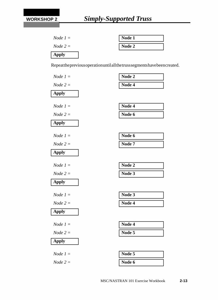
Repeatthepreviousoperationuntilallthetrusssegmentshavebeencreated.
Node 1 = Node 1
Node 2 = Node 2
Apply
Node 1 = Node 2
Node 2 = Node 4
Apply
Node 1 = Node 4
Node 2 = Node 6
Apply
Node 1 = Node 6
Node 2 = Node 7
Apply
Node 1 = Node 2
Node 2 = Node 3
Apply
Node 1 = Node 3
Node 2 = Node 4
Apply
Node 1 = Node 4
Node 2 = Node 5
Apply
Node 1 = Node 5
Node 2 = Node 6
MSC/NASTRAN 101 Exercise Workbook 2-13

Figure 2.1 - Nodal and Element Locations
6. Next, define a material using the specified modulus ofelasticity and allowable stresses.
Apply
Node 1 = Node 1
Node 2 = Node 3
Apply
Node 1 = Node 3
Node 2 = Node 5
Apply
Node 1 = Node 5
Node 2 = Node 7
Apply
◆ Materials
Action: Create
Object: Isotropic
Y
Z
1
2
3
4
5
6
7
1
2 3
45
6 7
8
9 10 11
X
2-14 MSC/NASTRAN 101 Exercise Workbook

WORKSHOP 2 Simply-Supported Truss
In theCurrent Constitutive Models data box, you will seeFailure - [n/a,,,,]- [Active] andLinear Elastic - [,,,,] - [Active] appear. Click onCancel toclose the form.
7. Define another material for the model, steel.
Method: Manual Input
Material Name: southern_pine
Input Properties ...
Constitutive Model: Linear Elastic
Elastic Modulus = 1.76E6
Density = 5.435E-5
Thermal Expan. Coeff = 3.00E-6
Reference Temperature = 72.0
Apply
Constitutive Model: Failure
Tension Stress Limit = ???(Enter material limit)
Compression Stress Limit = ???(Enter material Limit)
Apply
Cancel
◆ Materials
Action: Create
Object: Isotropic
Method: Manual Input
MSC/NASTRAN 101 Exercise Workbook 2-15

In theCurrent Constitutive Models data box, you will seeFailure - [n/a,,,,]- [Active] andLinear Elastic - [,,,,] - [Active] appear. Click onCancel toclose the form.
8. Next, reference the material that was created in the previous step. Definethe properties of the truss segments using the specified cross-sectionaldata.
Material Name: steel
Input Properties ...
Constitutive Model: Linear Elastic
Elastic Modulus = 2.90E7
Poisson Ratio = 0.32
Density = 7.349E-4
Thermal Expan. Coeff = 6.78E-6
Reference Temperature = 72.0
Apply
Constitutive Model: Failure
Tension Stress Limit = ???(Enter material limit)
Compression Stress Limit = ???(Enter material Limit)
Shear Stress Limit = ???(Enter material Limit)
Apply
Cancel
◆ Properties
Action: Create
2-16 MSC/NASTRAN 101 Exercise Workbook

WORKSHOP 2 Simply-Supported Truss
9. Enter the properties for the steel members using bar elements with thebeam library.
Dimension: 1 D
Type: Rod
Property Set Name: rod
Input Properties ...
Material Name: m:southern_pine
Area:???(Enter cross-sectional area)
OK
Select Members: Elm 5:8
Add
Apply
◆ Properties
Action: Create
Dimension: 1 D
Type: Beam
Property Set Name: steel_member_a
Input Properties ...
Material Name m:steel
Bar Orientation <0, 1, 0>
■ Associate Beam Section
MSC/NASTRAN 101 Exercise Workbook 2-17

Click the beam library icon:
10. Repeat the procedure for the remaining sections of the truss.
Action: Create
Type: Standard Shape
New Section Name: section_a
H 8
W1 3
W2 3
t 0.5
t1 0.5
t2 0.5
OK
OK
Select Members: Elm 9:11
Add
Apply
◆ Properties
Action: Create
Dimension: 1 D
Type: Beam
Property Set Name: steel_member_b
Input Properties ...
2-18 MSC/NASTRAN 101 Exercise Workbook

WORKSHOP 2 Simply-Supported Truss
Click the beam library icon:
11. Shrink the elements by 10% for clarity; this allows us to easily assess theelement connectivities. Use theDisplay/Finite Elements... option.
Material Name m:steel
Bar Orientation <0, 1, 0>
■ Associate Beam Section
Action: Create
Type: Standard Shape
New Section Name: section_b
H 6
W1 3
W2 3
t 0.5
t1 0.5
t2 0.5
OK
OK
Select Members: Elm 1:4
Add
Apply
Display/Finite Elements...
FEM Shrink: 0.10
Apply
MSC/NASTRAN 101 Exercise Workbook 2-19

12. Create three nodal constraints and apply them to the analysis model.These boundary conditions represent the simply-supported ends of thetruss, the fixed out of plane translations, and the contrained rotations..
12a. The left-hand support is defined as follows:
12b.The right-hand support is located at the opposite end of the truss.
Cancel
◆ Loads/BCs
Action: Create
Object: Displacement
Type: Nodal
New Set Name: pin
Input Data...
Translations < T1 T2 T3 > <0, 0, >
OK
Select Application Region...
Geometry Filter: ◆ FEM
Select Nodes: Node 1
Add
OK
Apply
◆ Loads/BCs
Action: Create
Object: Displacement
Type: Nodal
New Set Name: roller
Input Data...
Translations < T1 T2 T3 > < , 0, >
OK
2-20 MSC/NASTRAN 101 Exercise Workbook

WORKSHOP 2 Simply-Supported Truss
12c. The out of plane translations and out of plane rotations can be constrainedas follows:
Select Application Region...
Geometry Filter: ◆ FEM
Select Nodes: Node 7
Add
OK
Apply
◆ Loads/BCs
Action: Create
Object: Displacement
Type: Nodal
New Set Name: out_of_plane
Input Data...
Translations < T1 T2 T3 > < , ,0>
Rotations < R1 R2 R3 > <0, 0, >
OK
Select Application Region...
Geometry Filter: ◆ FEM
Select Nodes: Node 1:7
Add
OK
Apply
MSC/NASTRAN 101 Exercise Workbook 2-21

Figure 2.2 - Displacement Constraints
12d.Reset the display by selecting theReset Graphicsicon on theTop MenuBar.
13. Deactivate the entity labels by selecting theHide Labels icon on thetoolbar.
14. Create the gravity load..
◆ Loads/BCs
Action: Create
Object: Inertial Load
Type: Element Uniform
New Set Name: gravity_load
Input Data...
Load/BC Set Scale Factor: 386.4
Trans Accel < A1 A2 A3 > <0, -1, 0>
1
2 3
45
6 7
8
9 10 11
12345
345
345
345
345
345
2345
1
2
3
4
5
6
7
X
Y
Z
Reset Graphics
Hide Labels
2-22 MSC/NASTRAN 101 Exercise Workbook

WORKSHOP 2 Simply-Supported Truss
Since the gravity load acts uniformly on the body, the application regionis automatically set as the entire model.
15. Next, define the temperature load using fields.
Enter the data into the table as shown below.
OK
Apply
◆ Fields
Action: Create
Object: Spatial
Method: FEM
Field Name: temp_profile
Input Data ...
Entity Values
1 Node 1 45
2 Node 2 32
3 Node 3 60
4 Node 4 66
5 Node 5 60
6 Node 6 100
7 Node 7 80
OK
Apply
◆ Loads/BCs
Action: Create
Object: Temperature
MSC/NASTRAN 101 Exercise Workbook 2-23

Figure 2.3 - Temperature Loads
Type: Nodal
New Set Name: temperature_load
Input Data...
Spatial Fields: temp_profile(Click on this to select.)
OK
Select Application Region...
Geometry Filter: ◆ FEM
Select Nodes: Node 1:7
Add
OK
Apply
X
Y
Z
45.00
32.00
60.00
66.00
60.00
100.0
80.00
X
Y
Z
2-24 MSC/NASTRAN 101 Exercise Workbook
WORKSHOP 2 Simply-Supported Truss
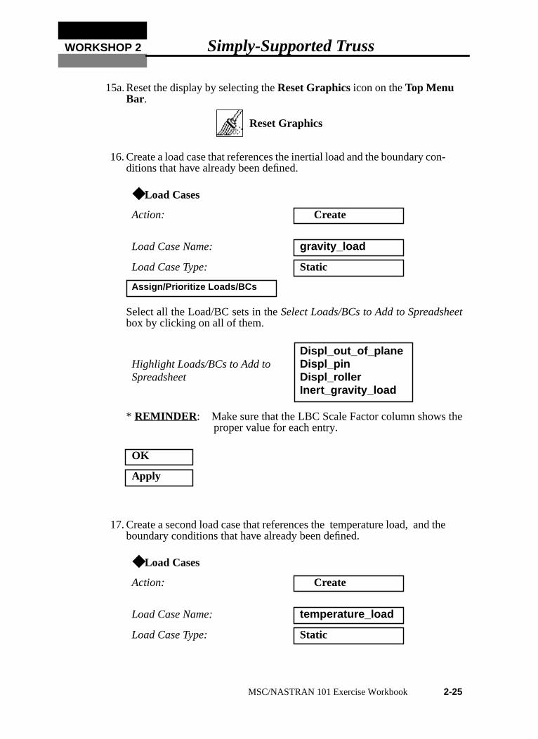
15a. Reset the display by selecting theReset Graphicsicon on theTop MenuBar.
16. Create a load case that references the inertial load and the boundary con-ditions that have already been defined.
Select all the Load/BC sets in theSelect Loads/BCs to Add to Spreadsheetbox by clicking on all of them.
* REMINDER : Make sure that the LBC Scale Factor column shows theproper value for each entry.
17. Create a second load case that references the temperature load, and theboundary conditions that have already been defined.
◆ Load Cases
Action: Create
Load Case Name: gravity_load
Load Case Type: Static
Assign/Prioritize Loads/BCs
Highlight Loads/BCs to Add toSpreadsheet
Displ_out_of_planeDispl_pinDispl_rollerInert_gravity_load
OK
Apply
◆ Load Cases
Action: Create
Load Case Name: temperature_load
Load Case Type: Static
Reset Graphics
MSC/NASTRAN 101 Exercise Workbook 2-25

:
Select all the Load/BC sets in theSelect Loads/BCs to Add to Spreadsheetbox by clicking on all of them.
If the inertial gravity load is in the spreadsheet, it can be removed as follows
17a. Close the form.
18. Now you are ready to generate an input file for analysis.
Click on theAnalysis radio button on theTop Menu Bar and complete theentries as shown here.
Assign/Prioritize Loads/BCs
Highlight Loads/BCs to Add toSpreadsheet
Displ_out_of_planeDispl_pinDispl_rollerTempe_temperature_load
Click the inertial gravity load in the spreadsheet.
Remove Selected Rows
OK
Apply
◆ Analysis
Action: Analyze
Object: Entire Model
Method: Analysis Deck
Job Name: prob2
Translation Parameters...
OUTPUT2 Format: Binary
MSC/NASTRAN Version:???Set accordingly, here it is 70.
OK
2-26 MSC/NASTRAN 101 Exercise Workbook
WORKSHOP 2 Simply-Supported Truss
s
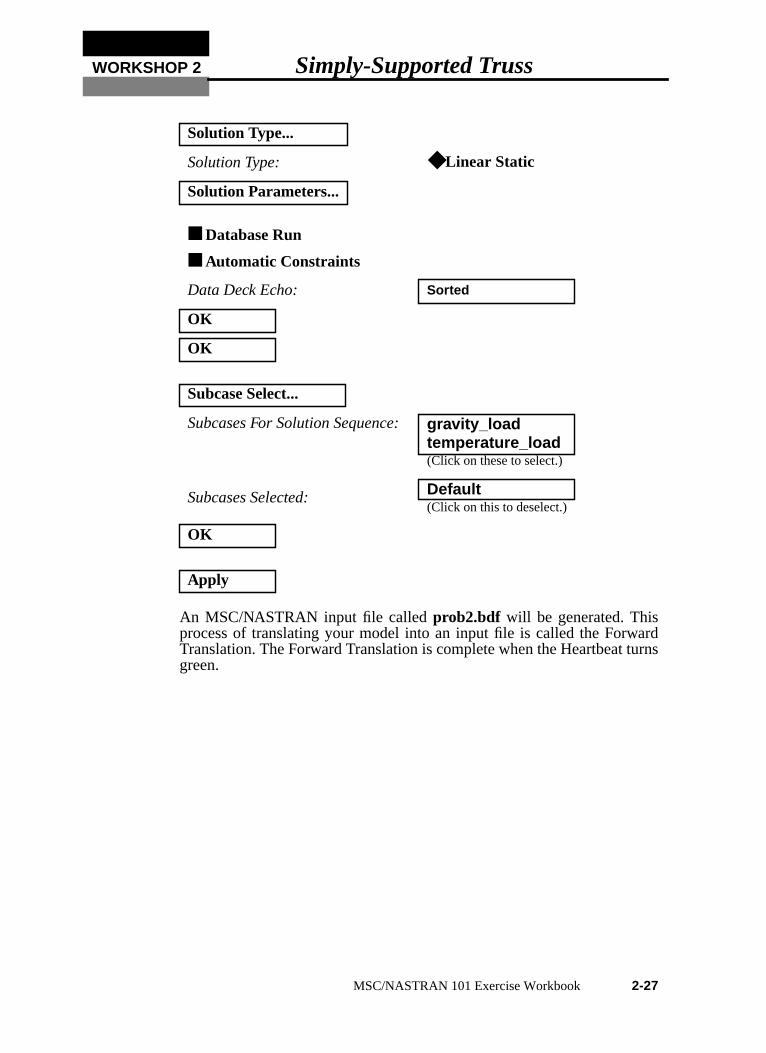
An MSC/NASTRAN input file calledprob2.bdf will be generated. Thisprocess of translating your model into an input file is called the ForwardTranslation. The Forward Translation is complete when the Heartbeat turngreen.
Solution Type...
Solution Type: ◆ Linear Static
Solution Parameters...
■ Database Run
■ Automatic Constraints
Data Deck Echo: Sorted
OK
OK
Subcase Select...
Subcases For Solution Sequence:gravity_loadtemperature_load(Click on these to select.)
Subcases Selected: Default(Click on this to deselect.)
OK
Apply
MSC/NASTRAN 101 Exercise Workbook 2-27
t
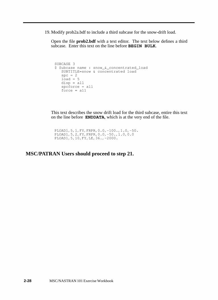
19. Modify prob2a.bdf to include a third subcase for the snow-drift load.
Open the fileprob2.bdf with a text editor. The text below defines a thirdsubcase. Enter this text on the line beforeBEGIN BULK.
SUBCASE 3$ Subcase name : snow_&_concentrated_load SUBTITLE=snow & concentrated load spc = 2 load = 5 disp = all spcforce = all force = all
This text describes the snow drift load for the third subcase, entire this texon the line beforeENDDATA, which is at the very end of the file.
PLOAD1,5,1,FY,FRPR,0.0,-100.,1.0,-50.PLOAD1,5,2,FY,FRPR,0.0,-50.,1.0,0.0PLOAD1,5,10,FY,LE,36.,-2000.
MSC/PATRAN Users should proceed to step 21.
2-28 MSC/NASTRAN 101 Exercise Workbook

WORKSHOP 2 Simply-Supported Truss
Generating an input file for MSC/NASTRAN Users:MSC/NASTRAN users can generate an input file using the data from theModel Description section at the beginning of the exercise. The resultshould be similar to the output below.
20. MSC/NASTRAN Input File: prob2a.dat
ID SEMINAR,PROB2TIME 5SOL 101CENDTITLE = GARAGE ROOF FRAMESUBTITLE = WOOD AND STEEL MEMBERS SPC = 20 DISP = ALL FORCE = ALL STRESS = ALL SPCFORCE = ALLSUBCASE 1 LABEL = GRAVITY LOAD LOAD = 1SUBCASE 2 LABEL = TEMPERATURE LOAD TEMP(LOAD) = 2SUBCASE 3 LABEL = SNOW AND CONCENTRATED LOAD LOAD = 3BEGIN BULKGRID,1,,0.0,0.0,0.0,,345GRID,2,,144.0,72.0,0.0,,345GRID,3,,192.0,0.0,0.0,,345GRID,4,,288.0,144.0,0.0,,345GRID,5,,384.0,0.0,0.0,,345GRID,6,,432.0,72.0,0.0,,345GRID,7,,576.0,0.0,0.0,,345CBAR,1,200,1,2,0.,1.,0.CBAR,2,200,2,4,0.,1.,0.CBAR,3,200,4,6,0.,1.,0.CBAR,4,200,6,7,0.,1.,0.CBAR,9,300,1,3,0.,1.,0.CBAR,10,300,3,5,0.,1.,0.CBAR,11,300,5,7,0.,1.,0.CROD,5,100,2,3CROD,6,100,3,4CROD,7,100,4,5CROD,8,100,5,6PROD,100,10,5.2PBARL 200 20 I 6. 3. 3. .5 .5 .5PBARL 300 20 I 8. 3. 3. .5 .5 .5MAT1,10,1.76+6,,,5.435-5,3.0-6,72. ,1900.,1900.MAT1,20,2.9+7,,.32,7.349-4,6.78-6,72. ,24000.,24000.,24000.GRAV,1,,386.4,0.0,-1.0,0.0PLOAD1,3,1,FY,FRPR,0.0,-100.,1.0,-50.
MSC/NASTRAN 101 Exercise Workbook 2-29

PLOAD1,3,2,FY,FRPR,0.0,-50.,1.0,0.0PLOAD1,3,10,FY,LE,36.,-2000.TEMP,2,1,45.TEMP,2,2,32.TEMP,2,3,60.TEMP,2,4,66.TEMP,2,5,60.TEMP,2,6,100.TEMP,2,7,80.SPC,20,1,12,0.0SPC,20,7,2,0.0ENDDATA
2-30 MSC/NASTRAN 101 Exercise Workbook

WORKSHOP 2 Simply-Supported Truss
SUBMITTING THE INPUT FILE FOR MSC/NASTRANand MSC/PATRAN USERS:
21. Submit the input file to MSC/NASTRAN for analysis.
21a. To submit the MSC/PATRAN.bdf file for analysis, find an availableUNIX shell window. At the command prompt enter:nastranprob2.bdf scr=yes. Monitor the run using the UNIX pscommand.
21b. To submit the MSC/NASTRAN.dat file for analysis, find anavailable UNIX shell window. At the command prompt enter:nastran prob2 scr=yes. Monitor the run using the UNIXpscommand.
22. When the run is completed, edit theprob2.f06 file and search for theword FATAL . If no matches exist, search for the wordWARNING .Determine whether existingWARNING messages indicate modelingerrors.
22a. While still editingprob2.f06, search for the word:
D I S P L A C E (spaces are necessary).
What are the components of the displacement vector for GRID 3 and 5(translation only)?
Gravity Load Case Temperature Load Case Snow Drift Load Case
Grid 3 Grid 3 Grid 3
Disp. X = Disp. X = Disp. X =
Disp. Y = Disp. Y = Disp. Y =
Disp. Z = Disp. Z = Disp. Z =
Grid 5 Grid 5 Grid 5
Disp. X = Disp. X = Disp. X =
Disp. Y = Disp. Y = Disp. Y =
Disp. Z = Disp. Z = Disp. Z =
MSC/NASTRAN 101 Exercise Workbook 2-31

Search for the word:
S I N G L E (spaces are necessary).
What are the components of the reaction force at GRID 1 and GRID 7?
Search for the word:
F O R C E D I S T (spaces are necessary).
What is the axial force in the BAR elements (CBAR) for each elementcase?
What is the axial force in CROD elements 7 and 8?
Gravity Load Case Temperature Load Case Snow Drift Load Case
GRID 1 GRID 1 GRID 1
T1 = T1 = T1 =
T2 = T2 = T2 =
T3 = T3 = T3 =
GRID 7 GRID 7 GRID 7
T1 = T1 = T1 =
T2 = T2 = T2 =
T3 = T3 = T3 =
Gravity Load Case Temperature Load Case Snow Drift Load Case
Element 4 Element 4 Element 4
PCT 1.000 PCT 1.000 PCT 1.000
PCT 0.000 PCT 0.000 PCT 0.000
Element 11 Element 11 Element 11
PCT 1.000 PCT 1.000 PCT 1.000
PCT 0.000 PCT 0.000 PCT 0.000
Gravity Load Case Temperature Load Case Snow Drift Load Case
Element 7 Element 7 Element 7
Element 8 Element 8 Element 8
2-32 MSC/NASTRAN 101 Exercise Workbook

WORKSHOP 2 Simply-Supported Truss
Search for the word:
S T R E S S (spaces are necessary).
What is the margin of safety for elements 6 and 11?
What is the Axial Stress for all elements 6 and 11?
Gravity Load Case Temperature Load Case Snow Drift Load Case
Element 6
PCT 1.000
Element 6
PCT 1.000
Element 6
PCT 1.000
PCT 0.000 PCT 0.000 PCT 0.000
Element 11 Element 11 Element 11
PCT 1.000 PCT 1.000 PCT 1.000
PCT 0.000 PCT 0.000 PCT 0.000
Gravity Load Case Temperature Load Case Snow Drift Load Case
Element 6
PCT 1.000
Element 6
PCT 1.000
Element 6
PCT 1.000
PCT 0.000 PCT 0.000 PCT 0.000
Element 11 Element 11 Element 11
PCT 1.000 PCT 1.000 PCT 1.000
PCT 0.000 PCT 0.000 PCT 0.000
MSC/NASTRAN 101 Exercise Workbook 2-33

Comparison of Results:
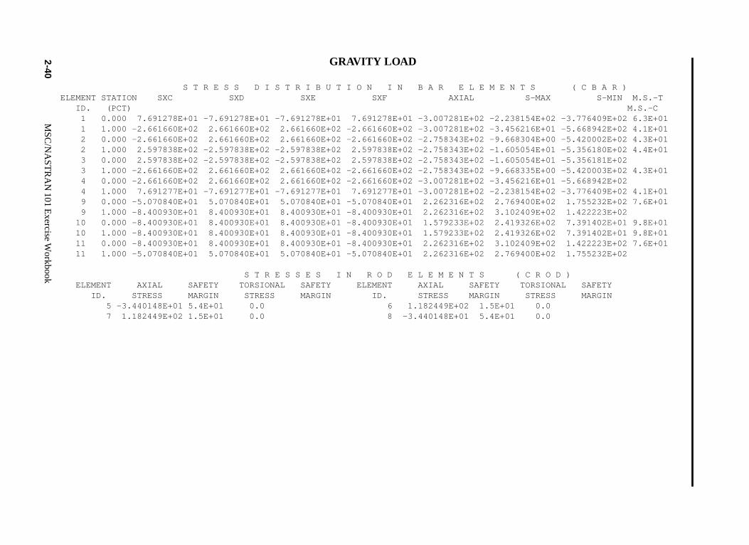
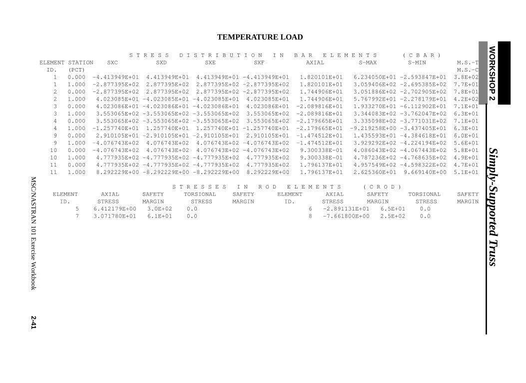
23. Compare the results obtained in the.f06file with the results on thenext page.
2-34 MSC/NASTRAN 101 Exercise Workbook

WO
RK
SH
OP
2 S
imply-S
upported Truss
MS
C/N
AS
TR
AN
101 Exercise W
orkbook2-35
GRAVITY LOAD D I S P L A C E M E N T V E C T O R
POINT ID. TYPE T1 T2 T3 R1 R2 R3 1 G 0.0 0.0 0.0 0.0 0.0 -1.810154E-04 2 G 9.097225E-03 -2.192763E-02 0.0 0.0 0.0 -5.905244E-06 3 G 1.497809E-03 -2.494602E-02 0.0 0.0 0.0 -6.952493E-05 4 G 2.020590E-03 -1.119851E-02 0.0 0.0 0.0 -1.510895E-19 5 G 2.543371E-03 -2.494602E-02 0.0 0.0 0.0 6.952493E-05 6 G -5.056045E-03 -2.192763E-02 0.0 0.0 0.0 5.905244E-06 7 G 4.041180E-03 0.0 0.0 0.0 0.0 1.810154E-04
TEMPERATURE LOAD D I S P L A C E M E N T V E C T O R
POINT ID. TYPE T1 T2 T3 R1 R2 R3 1 G 0.0 0.0 0.0 0.0 0.0 -1.640538E-04 2 G -2.911754E-02 -2.330577E-02 0.0 0.0 0.0 1.430237E-04 3 G -2.548194E-02 -1.314894E-02 0.0 0.0 0.0 1.492482E-04 4 G -7.371972E-02 9.976783E-03 0.0 0.0 0.0 3.720360E-04 5 G -4.109691E-02 3.371104E-02 0.0 0.0 0.0 9.121846E-05 6 G -4.592643E-02 3.897398E-02 0.0 0.0 0.0 6.057345E-06 7 G -4.358151E-02 0.0 0.0 0.0 0.0 -3.110594E-04
SNOW AND CONCENTRATED LOAD D I S P L A C E M E N T V E C T O R
POINT ID. TYPE T1 T2 T3 R1 R2 R3 1 G 0.0 0.0 0.0 0.0 0.0 -5.570779E-03 2 G 1.271998E-01 -2.928742E-01 0.0 0.0 0.0 2.406997E-03 3 G 1.541444E-02 -2.935280E-01 0.0 0.0 0.0 7.510522E-05 4 G 5.572549E-03 -7.900714E-02 0.0 0.0 0.0 1.498581E-03 5 G 2.198621E-02 -7.672425E-02 0.0 0.0 0.0 1.233808E-03 6 G 5.831808E-03 -6.193648E-02 0.0 0.0 0.0 -5.114951E-05 7 G 2.857348E-02 0.0 0.0 0.0 0.0 2.269690E-04

2-36M
SC
/NA
ST
RA
N101
Exercise
Workbook
GRAVITY LOAD F O R C E S O F S I N G L E - P O I N T C O N S T R A I N T
POINT ID. TYPE T1 T2 T3 R1 R2 R3 1 G -9.094947E-13 1.062826E+03 0.0 0.0 0.0 0.0 7 G 0.0 1.062826E+03 0.0 0.0 0.0 0.0
TEMPERATURE LOAD
F O R C E S O F S I N G L E - P O I N T C O N S T R A I N T
POINT ID. TYPE T1 T2 T3 R1 R2 R3 1 G 2.910383E-11 -1.818989E-12 0.0 0.0 0.0 0.0 7 G 0.0 -1.818989E-12 0.0 0.0 0.0 0.0
SNOW AND CONCENTRATED LOAD
F O R C E S O F S I N G L E - P O I N T C O N S T R A I N T
POINT ID. TYPE T1 T2 T3 R1 R2 R3 1 G 1.164999E-04 1.320833E+04 0.0 0.0 0.0 0.0 7 G 0.0 3.191667E+03 0.0 0.0 0.0 0.0

WO
RK
SH
OP
2 S
imply-S
upported Truss
MS
C/N
AS
TR
AN
101 Exercise W
orkbook2-37
GRAVITY LOAD F O R C E D I S T R I B U T I O N I N B A R E L E M E N T S ( C B A R ) ELEMENT STATION BEND-MOMENT SHEAR FORCE AXIAL ID. (PCT) PLANE 1 PLANE 2 PLANE 1 PLANE 2 FORCE TORQUE 1 0.000 -7.167844E+02 0.0 -1.985941E+01 0.0 -1.654005E+03 0.0 1 1.000 2.480519E+03 0.0 -1.985941E+01 0.0 -1.654005E+03 0.0 2 0.000 2.480519E+03 0.0 3.044506E+01 0.0 -1.517089E+03 0.0 2 1.000 -2.421041E+03 0.0 3.044506E+01 0.0 -1.517089E+03 0.0 3 0.000 -2.421041E+03 0.0 -3.044506E+01 0.0 -1.517089E+03 0.0 3 1.000 2.480519E+03 0.0 -3.044506E+01 0.0 -1.517089E+03 0.0 4 0.000 2.480519E+03 0.0 1.985941E+01 0.0 -1.654005E+03 0.0 4 1.000 -7.167843E+02 0.0 1.985941E+01 0.0 -1.654005E+03 0.0 9 0.000 7.167844E+02 0.0 -2.451677E+00 0.0 1.470505E+03 0.0 9 1.000 1.187506E+03 0.0 -2.451677E+00 0.0 1.470505E+03 0.0 10 0.000 1.187506E+03 0.0 -2.842171E-14 0.0 1.026502E+03 0.0 10 1.000 1.187506E+03 0.0 -2.842171E-14 0.0 1.026502E+03 0.0 11 0.000 1.187506E+03 0.0 2.451677E+00 0.0 1.470505E+03 0.0 11 1.000 7.167844E+02 0.0 2.451677E+00 0.0 1.470505E+03 0.0
F O R C E S I N R O D E L E M E N T S ( C R O D ) ELEMENT AXIAL ELEMENT AXIAL ID. FORCE TORQUE ID. FORCE TORQUE 5 -1.802138E+02 0.0 6 6.202254E+02 0.0 7 6.202254E+02 0.0 8 -1.802138E+02 0.0

2-38M
SC
/NA
ST
RA
N101
Exercise
Workbook
TEMPERATURE LOAD F O R C E D I S T R I B U T I O N I N B A R E L E M E N T S ( C B A R ) ELEMENT STATION BEND-MOMENT SHEAR FORCE AXIAL ID. (PCT) PLANE 1 PLANE 2 PLANE 1 PLANE 2 FORCE TORQUE 1 0.000 4.113555E+02 0.0 -1.410100E+01 0.0 1.001056E+02 0.0 1 1.000 2.681573E+03 0.0 -1.410100E+01 0.0 1.001056E+02 0.0 2 0.000 2.681573E+03 0.0 1.898485E+01 0.0 9.596985E+01 0.0 2 1.000 -3.749292E+02 0.0 1.898485E+01 0.0 9.596985E+01 0.0 3 0.000 -3.749293E+02 0.0 1.823842E+01 0.0 -1.149399E+02 0.0 3 1.000 -3.311259E+03 0.0 1.823842E+01 0.0 -1.149399E+02 0.0 4 0.000 -3.311259E+03 0.0 -2.129528E+01 0.0 -1.198816E+02 0.0 4 1.000 1.172143E+02 0.0 -2.129528E+01 0.0 -1.198816E+02 0.0 9 0.000 -4.113555E+02 0.0 -3.215626E+01 0.0 -9.584331E+01 0.0 9 1.000 5.762646E+03 0.0 -3.215626E+01 0.0 -9.584331E+01 0.0 10 0.000 5.762646E+03 0.0 6.518988E+01 0.0 6.045220E+00 0.0 10 1.000 -6.753811E+03 0.0 6.518988E+01 0.0 6.045220E+00 0.0 11 0.000 -6.753811E+03 0.0 -3.456561E+01 0.0 1.167489E+02 0.0 11 1.000 -1.172141E+02 0.0 -3.456561E+01 0.0 1.167489E+02 0.0
F O R C E S I N R O D E L E M E N T S ( C R O D ) ELEMENT AXIAL ELEMENT AXIAL ID. FORCE TORQUE ID. FORCE TORQUE 5 3.334333E+01 0.0 6 -1.503388E+02 0.0 7 1.597325E+02 0.0 8 -3.984136E+01 0.0

WO
RK
SH
OP
2 S
imply-S
upported Truss
MS
C/N
AS
TR
AN
101 Exercise W
orkbook2-39
SNOW AND CONCENTRATED LOAD
F O R C E D I S T R I B U T I O N I N B A R E L E M E N T S ( C B A R ) ELEMENT STATION BEND-MOMENT SHEAR FORCE AXIAL ID. (PCT) PLANE 1 PLANE 2 PLANE 1 PLANE 2 FORCE TORQUE 1 0.000 -1.098263E+05 0.0 -5.620021E+03 0.0 -1.972972E+04 0.0 1 1.000 -6.902036E+04 0.0 4.039792E+03 0.0 -1.489982E+04 0.0 2 0.000 -6.902037E+04 0.0 -2.410550E+03 0.0 -1.409352E+04 0.0 2 1.000 -2.652932E+04 0.0 8.093880E+02 0.0 -1.248356E+04 0.0 3 0.000 -2.652932E+04 0.0 -2.326103E+02 0.0 -7.333517E+03 0.0 3 1.000 1.092021E+04 0.0 -2.326103E+02 0.0 -7.333517E+03 0.0 4 0.000 1.092021E+04 0.0 1.182581E+02 0.0 -7.289658E+03 0.0 4 1.000 -8.118965E+03 0.0 1.182581E+02 0.0 -7.289658E+03 0.0 9 0.000 1.098263E+05 0.0 6.417671E+02 0.0 1.513345E+04 0.0 9 1.000 -1.339296E+04 0.0 6.417671E+02 0.0 1.513345E+04 0.0 10 0.000 -1.339295E+04 0.0 -1.562901E+03 0.0 6.451971E+03 0.0 10 1.000 -2.531606E+04 0.0 4.370995E+02 0.0 6.451971E+03 0.0 11 0.000 -2.531606E+04 0.0 -1.741408E+02 0.0 6.467182E+03 0.0 11 1.000 8.118966E+03 0.0 -1.741408E+02 0.0 6.467182E+03 0.0
F O R C E S I N R O D E L E M E N T S ( C R O D ) ELEMENT AXIAL ELEMENT AXIAL ID. FORCE TORQUE ID. FORCE TORQUE 5 -6.500541E+03 0.0 6 9.150221E+03 0.0 7 3.810205E+02 0.0 8 3.535989E+02 0.0
2-40M
SC
/NA
ST
RA
N101
Exercise
Workbook
09E+02 6.3E+0142E+02 4.1E+0102E+02 4.3E+0180E+02 4.4E+0181E+0203E+02 4.3E+0142E+0209E+02 4.1E+0132E+02 7.6E+0123E+0202E+01 9.8E+0102E+01 9.8E+0123E+02 7.6E+0132E+02
FETY
GRAVITY LOAD
S T R E S S D I S T R I B U T I O N I N B A R E L E M E N T S ( C B A R ) ELEMENT STATION SXC SXD SXE SXF AXIAL S-MAX S-MIN M.S.-T ID. (PCT) M.S.-C 1 0.000 7.691278E+01 -7.691278E+01 -7.691278E+01 7.691278E+01 -3.007281E+02 -2.238154E+02 -3.7764 1 1.000 -2.661660E+02 2.661660E+02 2.661660E+02 -2.661660E+02 -3.007281E+02 -3.456216E+01 -5.6689 2 0.000 -2.661660E+02 2.661660E+02 2.661660E+02 -2.661660E+02 -2.758343E+02 -9.668304E+00 -5.4200 2 1.000 2.597838E+02 -2.597838E+02 -2.597838E+02 2.597838E+02 -2.758343E+02 -1.605054E+01 -5.3561 3 0.000 2.597838E+02 -2.597838E+02 -2.597838E+02 2.597838E+02 -2.758343E+02 -1.605054E+01 -5.3561 3 1.000 -2.661660E+02 2.661660E+02 2.661660E+02 -2.661660E+02 -2.758343E+02 -9.668335E+00 -5.4200 4 0.000 -2.661660E+02 2.661660E+02 2.661660E+02 -2.661660E+02 -3.007281E+02 -3.456216E+01 -5.6689 4 1.000 7.691277E+01 -7.691277E+01 -7.691277E+01 7.691277E+01 -3.007281E+02 -2.238154E+02 -3.7764 9 0.000 -5.070840E+01 5.070840E+01 5.070840E+01 -5.070840E+01 2.262316E+02 2.769400E+02 1.7552 9 1.000 -8.400930E+01 8.400930E+01 8.400930E+01 -8.400930E+01 2.262316E+02 3.102409E+02 1.4222 10 0.000 -8.400930E+01 8.400930E+01 8.400930E+01 -8.400930E+01 1.579233E+02 2.419326E+02 7.3914 10 1.000 -8.400930E+01 8.400930E+01 8.400930E+01 -8.400930E+01 1.579233E+02 2.419326E+02 7.3914 11 0.000 -8.400930E+01 8.400930E+01 8.400930E+01 -8.400930E+01 2.262316E+02 3.102409E+02 1.4222 11 1.000 -5.070840E+01 5.070840E+01 5.070840E+01 -5.070840E+01 2.262316E+02 2.769400E+02 1.7552
S T R E S S E S I N R O D E L E M E N T S ( C R O D ) ELEMENT AXIAL SAFETY TORSIONAL SAFETY ELEMENT AXIAL SAFETY TORSIONAL SA ID. STRESS MARGIN STRESS MARGIN ID. STRESS MARGIN STRESS MARGIN 5 -3.440148E+01 5.4E+01 0.0 6 1.182449E+02 1.5E+01 0.0 7 1.182449E+02 1.5E+01 0.0 8 -3.440148E+01 5.4E+01 0.0
WO
RK
SH
OP
2 S
imply-S
upported Truss
TEMPERATURE LOAD
S-MAX S-MIN M.S.-TM.S.-C
0E+01 -2.593847E+01 3.8E+026E+02 -2.695385E+02 7.7E+016E+02 -2.702905E+02 7.8E+012E+01 -2.278179E+01 4.2E+020E+01 -6.112902E+01 7.1E+013E+02 -3.762047E+02 6.3E+018E+02 -3.771031E+02 7.1E+01E+00 -3.437405E+01 6.3E+01
3E+01 -4.384618E+01 6.0E+012E+02 -4.224194E+02 5.6E+013E+02 -4.067443E+02 5.8E+016E+02 -4.768635E+02 4.9E+019E+02 -4.598322E+02 4.7E+010E+01 9.669140E+00 5.1E+01
L SAFETY TORSIONAL SAFETYMARGIN STRESS MARGIN
MS
C/N
AS
TR
AN
101 Exercise W
orkbook2-41
S T R E S S D I S T R I B U T I O N I N B A R E L E M E N T S ( C B A R )ELEMENT STATION SXC SXD SXE SXF AXIAL
ID. (PCT)1 0.000 -4.413949E+01 4.413949E+01 4.413949E+01 -4.413949E+01 1.820101E+01 6.234051 1.000 -2.877395E+02 2.877395E+02 2.877395E+02 -2.877395E+02 1.820101E+01 3.059402 0.000 -2.877395E+02 2.877395E+02 2.877395E+02 -2.877395E+02 1.744906E+01 3.051882 1.000 4.023085E+01 -4.023085E+01 -4.023085E+01 4.023085E+01 1.744906E+01 5.767993 0.000 4.023086E+01 -4.023086E+01 -4.023086E+01 4.023086E+01 -2.089816E+01 1.933273 1.000 3.553065E+02 -3.553065E+02 -3.553065E+02 3.553065E+02 -2.089816E+01 3.344084 0.000 3.553065E+02 -3.553065E+02 -3.553065E+02 3.553065E+02 -2.179665E+01 3.335094 1.000 -1.257740E+01 1.257740E+01 1.257740E+01 -1.257740E+01 -2.179665E+01 -9.2192589 0.000 2.910105E+01 -2.910105E+01 -2.910105E+01 2.910105E+01 -1.474512E+01 1.435599 1.000 -4.076743E+02 4.076743E+02 4.076743E+02 -4.076743E+02 -1.474512E+01 3.92929
10 0.000 -4.076743E+02 4.076743E+02 4.076743E+02 -4.076743E+02 9.300338E-01 4.0860410 1.000 4.777935E+02 -4.777935E+02 -4.777935E+02 4.777935E+02 9.300338E-01 4.7872311 0.000 4.777935E+02 -4.777935E+02 -4.777935E+02 4.777935E+02 1.796137E+01 4.9575411 1.000 8.292229E+00 -8.292229E+00 -8.292229E+00 8.292229E+00 1.796137E+01 2.62536
S T R E S S E S I N R O D E L E M E N T S ( C R O D )ELEMENT AXIAL SAFETY TORSIONAL SAFETY ELEMENT AXIA
ID. STRESS MARGIN STRESS MARGIN ID. STRESS 5 6.412179E+00 3.0E+02 0.0 6 -2.891131E+01 6.5E+01 0.0 7 3.071780E+01 6.1E+01 0.0 8 -7.661800E+00 2.5E+02 0.0

S-MAX S-MIN M.S.-TM.S.-C
87E+04 5.6E-0112E+04 1.4E+0020E+03 1.4E+0000E+03 3.7E+0030E+03 1.5E+0133E+03 4.7E+0059E+0378E+03 8.6E+0062E+03 1.4E+0048E+03 3.4E+00605E+01 1.1E+01558E+02 7.6E+00159E+02 7.6E+00806E+02 2.9E+01
AXIAL SAFETY TORSIONAL SAFETYESS MARGIN STRESS MARGIN
2-42M
SC
/NA
ST
RA
N101
Exercise
Workbook
SNOW AND CONCENTRATED LOAD
S T R E S S D I S T R I B U T I O N I N B A R E L E M E N T S ( C B A R )ELEMENT STATION SXC SXD SXE SXF AXIAL
ID. (PCT) 1 0.000 1.178464E+04 -1.178464E+04 -1.178464E+04 1.178464E+04 -3.587222E+03 8.197420E+03 -1.5371 1 1.000 7.406060E+03 -7.406060E+03 -7.406060E+03 7.406060E+03 -2.709058E+03 4.697002E+03 -1.0115 2 0.000 7.406061E+03 -7.406061E+03 -7.406061E+03 7.406061E+03 -2.562459E+03 4.843602E+03 -9.9685 2 1.000 2.846663E+03 -2.846663E+03 -2.846663E+03 2.846663E+03 -2.269737E+03 5.769253E+02 -5.1164 3 0.000 2.846663E+03 -2.846663E+03 -2.846663E+03 2.846663E+03 -1.333367E+03 1.513296E+03 -4.1800 3 1.000 -1.171767E+03 1.171767E+03 1.171767E+03 -1.171767E+03 -1.333367E+03 -1.616001E+02 -2.5051 4 0.000 -1.171767E+03 1.171767E+03 1.171767E+03 -1.171767E+03 -1.325392E+03 -1.536259E+02 -2.4971 4 1.000 8.711855E+02 -8.711855E+02 -8.711855E+02 8.711855E+02 -1.325392E+03 -4.542069E+02 -2.1965 9 0.000 -7.769585E+03 7.769585E+03 7.769585E+03 -7.769585E+03 2.328223E+03 1.009781E+04 -5.4413 9 1.000 9.474753E+02 -9.474753E+02 -9.474753E+02 9.474753E+02 2.328223E+03 3.275699E+03 1.3807 10 0.000 9.474749E+02 -9.474749E+02 -9.474749E+02 9.474749E+02 9.926110E+02 1.940086E+03 4.513 10 1.000 1.790967E+03 -1.790967E+03 -1.790967E+03 1.790967E+03 9.926110E+02 2.783578E+03 -7.983 11 0.000 1.790967E+03 -1.790967E+03 -1.790967E+03 1.790967E+03 9.949510E+02 2.785918E+03 -7.960 11 1.000 -5.743705E+02 5.743705E+02 5.743705E+02 -5.743705E+02 9.949510E+02 1.569322E+03 4.205
S T R E S S E S I N R O D E L E M E N T S ( C R O D )ELEMENT AXIAL SAFETY TORSIONAL SAFETY ELEMENT
ID. STRESS MARGIN STRESS MARGIN ID. STR 5 -1.250104E+03 5.2E-01 0.0 6 1.759658E+03 8.0E-02 0.0 7 7.327319E+01 2.5E+01 0.0 8 6.799979E+01 2.7E+01 0.0

WORKSHOP 2 Simply-Supported Truss
24. MSC/NASTRAN Users have finished this exercise. MSC/PATRANUsers should proceed to the next step.
25. Proceed with the Reverse Translation process, that is, importing theprob2.op2 results file into MSC/PATRAN. To do this, return to theAnalysis form and proceed as follows:
26. When the translation is complete and the Heartbeat turns green, bring uptheResultsform.
◆ Analysis
Action: Read Output 2
Object: Result Entities
Method: Translate
Select Results File...
Filter
Available Files: prob2.op2
OK
Apply
◆ Results
Action: Create
Object: Fringe
Select Results Case(s): temperature_load, Static Subcase
Select Fringe Result: Displacements, Translational
Quantity: Magnitude
MSC/NASTRAN 101 Exercise Workbook 2-43

To change the target entites of the plot, click on theTarget Entitiesicon.
To change the display attributes of the plot, click on theDisplayAttributes icon.
To change the plot options, click on thePlot Options icon.
26a. Next, add the deformation options to the plot.
Target Entity: Materials
Select Materials:southern_pinesteel
Style: Discrete/Smooth
Coordinate Transformation: None
Apply
◆ Results
Action: Create
Object: Deformation
Target Entites
Display Attributes
Plot Options
2-44 MSC/NASTRAN 101 Exercise Workbook

WORKSHOP 2 Simply-Supported Truss
To change the target entites of the plot, click on theTarget Entitesicon.
To change the properties of the plot, click on theDisplay Attributesicon.
If you wish to reset your display graphics to the state it was in beforeyou began post-processing your model, remember to select theResetGraphics icon.
You can go back and select anyResults Case, Fringe Results orDeformation Resultsyou are interested in.
Quit MSC/PATRAN when you have completed this exercise.
Target Entity: Materials
Select Materials:southern_pinesteel
■ Show Undeformed
Line Style:
Apply
Target Entities
Display Attributes
Reset Graphics
MSC/NASTRAN 101 Exercise Workbook 2-45

2-46 MSC/NASTRAN 101 Exercise Workbook