Linear Response History Analysis of Concrete Dams - …€¦ · Linear Response History Analysis of...
37
Linear Response History Analysis of Concrete Dams Anil K. Chopra Workshop on Seismic Analysis of Concrete Dams USSD Annual Meeting Anaheim, California 2017 1
Transcript of Linear Response History Analysis of Concrete Dams - …€¦ · Linear Response History Analysis of...

Linear Response History Analysis of Concrete Dams
Anil K. Chopra
Workshop on Seismic Analysis of Concrete DamsUSSD Annual Meeting
Anaheim, California 20171

Complex System Geometry
Three-dimensional system
Reservoir: unbounded in the upstream direction
Foundation: semi-unbounded domain
2
Standard Finite Element Analysis
Ignores radiation damping into foundation rock, impounded water, and reservoir bottom sediments
3
Fixed boundaries

Popular Finite Element Analysis
Represent hydrodynamics by added mass, i.e., neglect water compressibility
Assume foundation rock to be massless
Surface ground motion applied at bottom boundary
4
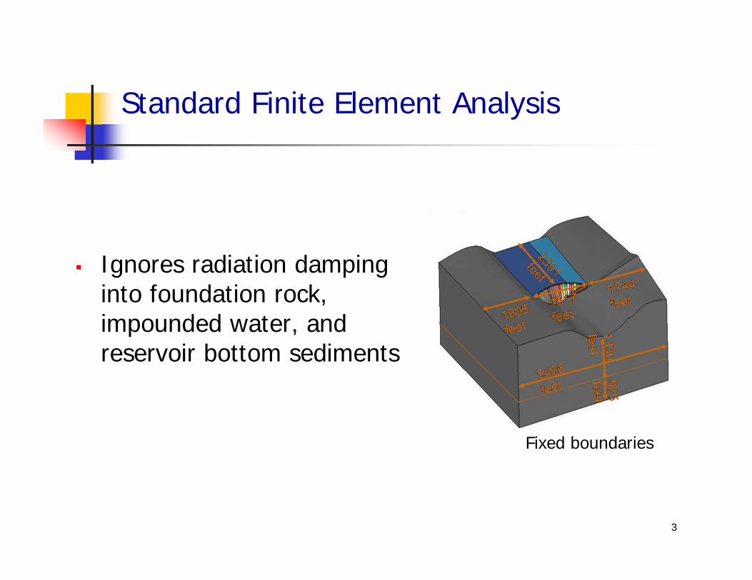
Popular Finite Element Analysis
Convenient to implement in commercial FE software
• SAP 2000, ABAQUS, FLAC, LSDYNA, …
But the problem solved is not close to the real problem
Modeling of dam-water-foundation system inadequate
Specification of ground motion contradicts recordings
5

Specification of Ground Motion
Surface ground motion applied to bottom boundary
Known to be incorrect
Recorded motions at depth differ from surface motions
6
Fixed boundaries

Modeling of dam-water-foundation interaction
Spatial variations in ground motion
Validation of Direct Finite Element Methods
Discussion Topics
7
Outline

Research 1980-1996
Reclamation Investigations 1996-
8
Part I: Modeling of Dam-Water-Foundation Interaction
Bureau of Reclamation Program to Evaluate Existing Dams
Major program, started in 1996
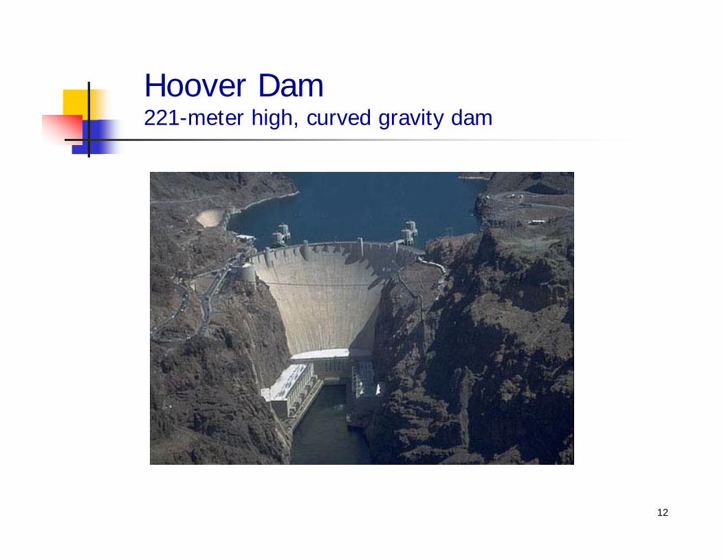
Twelve dams were investigated, including: Hoover dam (221 meter-high
curved gravity dam)
9

Hoover Dam221-meter high, curved gravity dam
10

Evaluation of Hoover Dam
Stresses computed by popular finite element analysis Massless foundation rock Added water mass
Dam will crack through the thickness
Did not seem credible to Reclamation engineers
2204 lb/in2 (15196 kPa)
11
Hoover Dam221-meter high, curved gravity dam
12

Hoover Dam: Cross Section
13

Dam-foundation interactionMassless foundation rock
(flexibility only) 758 lb/in2 (5226 kPa) 2204 lb/in2 (15196 kPa)
Hoover Dam
Important to Include Foundation Rock Inertia and Damping (Material and Radiation)
14
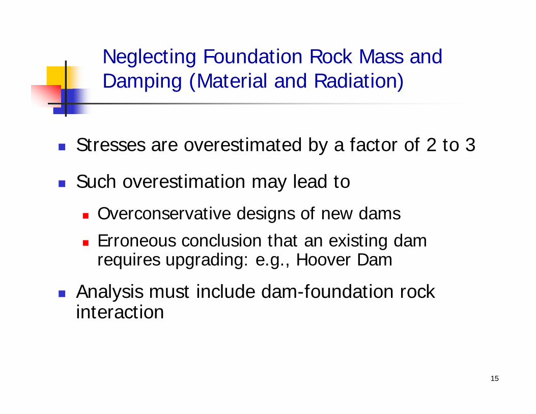
Neglecting Foundation Rock Mass and Damping (Material and Radiation)
Stresses are overestimated by a factor of 2 to 3
Such overestimation may lead to
Overconservative designs of new dams Erroneous conclusion that an existing dam
requires upgrading: e.g., Hoover Dam
Analysis must include dam-foundation rock interaction
15

Stresses May Be Underestimated by Neglecting Water Compressibility
Monticello Dam
Water compressibility considered Water compressibility neglected1565 lb/in2 (10790 kPa) 1309 lb/in2 (9025 kPa)
16

Morrow Point Dam
Water compressibility considered Water compressibility neglected 1513 lb/in2 (10431 kPa) 2215 lb/in2 (15272 kPa)
Stresses May Be Overestimated by Neglecting Water Compressibility
17

18
Part II: Spatial Variations in Ground Motion

Pacoima Dam, California, USA113 meters high
19

Instrumentation at Pacoima Dam
CDMG Sensor Locations20

Recorded Motions at Pacoima DamNorthridge Earthquake, 1994
882
735
429
0 1 2 3 4 5 6 7 8 9 10 11-1000
-500
0
500
1000
Time, sec
Acc
eler
atio
n, c
m/s2
9
12 15
21

Pacoima Dam: Spatial Variations in Interface Motions Are LargeNorthridge Earthquake, 1994
Missing segments estimated by Alves & Hall (2004)
882
735
429
0 1 2 3 4 5 6 7 8 9 10 11-1000
-500
0
500
1000
Time, sec
Acc
eler
atio
n, c
m/s
2
9
12 15
22
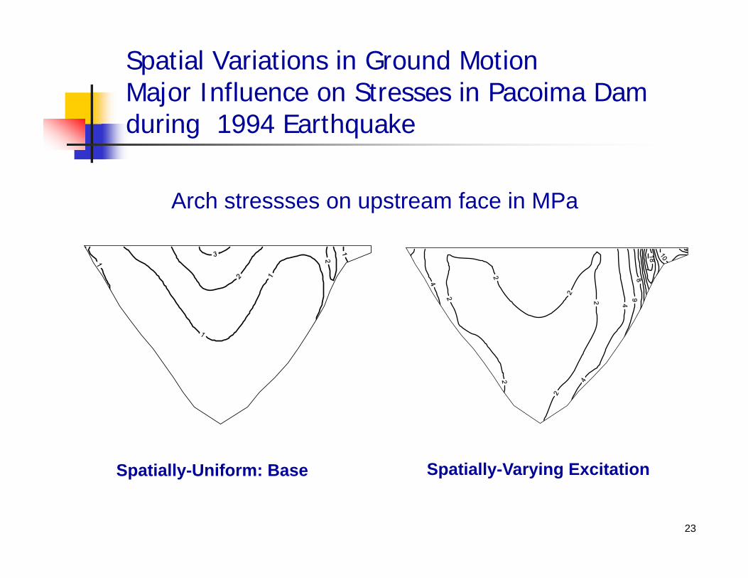
Spatial Variations in Ground MotionMajor Influence on Stresses in Pacoima Dam during 1994 Earthquake
Spatially-Uniform: Base Spatially-Varying Excitation
Arch stressses on upstream face in MPa
23

Pacoima Dam, California, USA113 meters high
24

Pacoima Dam, Cracking Visible
25

Waves of different types (P, SV, SH, Rayleigh, and Love) incident from different parts of the fault and from different directions
Capability to predict spatially varying motions is limited. Impractical at this time.
Pragmatic approach: assume vertically propagating motions; models variations over height only.
26
Specifying Spatially Varying Ground Motions

27
Part III: Validation of Direct Finite Element Methods

Available Open Source MethodsNeither offer a fully satisfactory solution
Substructure method(frequency domain)
Direct FE method(time domain)
Special-purpose software EAGD84 / EACD-3D
Rigorous (analytical) treatment of unbounded domains
Restricted to linear analysis
Recorders
DamReservoir
Foundation-rock
Commercial FE software Abaqus, LS-DYNA, etc.
Nonlinear analysis Modeling of unbounded domains
and earthquake input not always satisfactory
28

Direct FE Analysis Procedure
29
Finite elements used for all domains Standard solid elements for dam
and foundation rock Fluid elements for reservoir Surface elements to model
reservoir bottom absorption
Nonlinear mechanisms can be modeled Concrete cracking Separation and sliding at joints
and interfaces

Unbounded Domains Require Special Attention
30
Unbounded domains must be truncated and wave-absorbing boundaries applied at these truncations
Radiation condition to be satisfied at the boundary:
e.g., in the x-direction1u ux c t

31
Seismic Input Must Be Specified as ‘Effective Earthquake Forces’ at All Boundaries
Prescribing displacements at the model truncations will lead to a reflective boundary
Instead, Effective Earthquake Forces must be applied at the boundaries or in a layer of elements inside of boundaries
Several formulations are available using “free-field motion” as input, e.g.:
Traction input (Zienkiewicz, Wolf) Domain Reduction Method (Bielak et.
al.)

32
Free-Field Motion at Boundaries
Ground motion defined at a control point on foundation-rock surface
“Free-field” motion at all boundaries determined by deconvolution and convolution of surface motion
Effective earthquake forces computed from boundary motion and applied to main model

33
Morrow Point Dam
Near symmetric, single centered arch dam located on Gunnison River, CO Forced vibration tests have measured damping of 1.5 - 3% for
antisymmetric modes and around 4% for symmetric modes Analysis parameters chosen to be consistent with experimental data
Viscous damping: 1% in dam concrete and 2% in rock Wave reflection coefficient, = 0.80
34
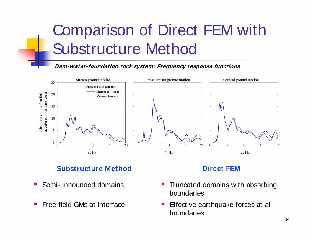
Comparison of Direct FEM with Substructure MethodDam-water-foundation rock system: Frequency response functions
Substructure Method Direct FEM
Semi-unbounded domains Truncated domains with absorbing boundaries
Free-field GMs at interface Effective earthquake forces at all boundaries

Forces on Side Boundaries Should Not Be Ignored
Observations: Dam response is in significant error when excluding forces at side boundaries Errors arise because side boundaries “drains” energy as the seismic waves
propagates upward
2D dam-foundation rock system: Frequency response functions
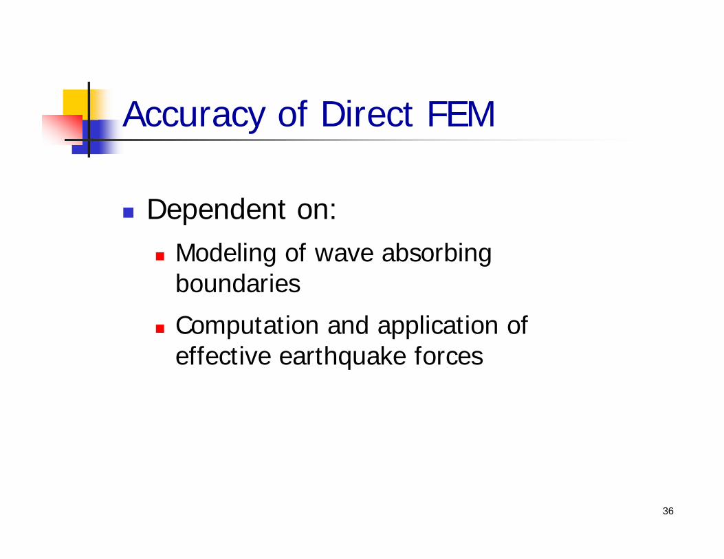
Dependent on: Modeling of wave absorbing
boundaries
Computation and application of effective earthquake forces
36
Accuracy of Direct FEM

Mass of foundation rock should be modeled
Compressibility of water should be included
Spatial variations in ground motion around the canyon should be considered
Direct FEM must be validated against independent analysis
37
Discussion Topics