
Linear drainage solutions for every application
20
THE UK’S NUMBER ONE EDITION 3 40 Over Over Linear drainage solutions for every application
Transcript of Linear drainage solutions for every application

T H E U K ’ S N U M B E R O N E
EDITION 3
40OverOver
Linear drainage
solutions
for every application

CONTENTS
TEL: 01733 765316FAX: 01733 246920
| 2 | CONTENTS | www.clark-drain.com | [email protected]
Due to our continual development programme, we reserve the right to upgrade products without prior notice.
Pre-sloped system
Stepped system
Constant channels (natural fall)
Introduction Page 3
Domestic Polymer and Polypropylene Ranges Page 4–5
Med-Heavy Duty SE10 Series Page 6–7
Med-Heavy Duty SSE10 Series Page 8–9
Med-Heavy Duty SE/15/20/30 Series Page 10
Med-Heavy Duty SSE 10, 20, 30 Series Page 10
Block Slot Page 11
Heavy Duty CE10 Series Page 12–13
Heavy Duty CE15/20/30 Series Page 14
Gully Assembly and End Caps Page 15
CD ‘M’ Series Page 16–17
Installation Procedure Page 18–19
LOAD CLASS DESCRIPTIONS
Class A Up to 15kN Pedestrian and cycleways, domestic drives
Class B Up to 125kN Pedestrian precincts, light vehicles, private car parks and drives
Class C Up to 250kN Parkside areas, service stations (cars), car parks
Class D Up to 400kN Cross drainage of roads and motorways
Class E Up to 600kN Industrial areas, heavy wheel loads, slow-moving HGVs and service stations
Class F Up to 900kN Airport runways, heavy industrial installations, forklifts, service yards and lorry parks
TYPES OF SLOPE OPTIONS
H0
0
H2
0
*Step Connector
**
| www.clark-drain.com | [email protected] | INTRODUCTION | 3 |Due to our continual development programme, we reserve the right to upgrade products without prior notice.
INTRODUCTION
TEL: 01733 765316FAX: 01733 246920
CLARK-DRAIN LTD is renowned all over the world for the innovative drainage products it brings to the market.
Over the past few years, Clark-Drain has set about developing its own linear drainage system, with a team ofindividuals that each have over 10 years experience in the linear drainage markets of UK and Europe. Aftermuch research and discussions with leading consulting engineers, specifiers, clients and users of lineardrainage, Clark-Drain created the Clark-Drain Polymer concrete linear drainage range.
The range includes many new and unique features which bring linear drainage into a new era:
Internally and externally sloped channels – (considerably reducing installation costs)
Internally glazed channels – (giving greater efficiency to the system)
All channels with seal as standard – (will become industry standard)
Narrow slot (6mm) gratings in all widths – (more wider channels now being used in public areas)
CatchLock on CE range – (more efficient cleaning of channels)
New SpringLock on SE/SSE range – (more efficient cleaning of channels)
M range – (also available with colour options)
New Block-Slot drainage – (access point c/w integral lifting keys for easy access)
The above are just some of the latest features within the range and as an innovative company more new ideas,
products and innovations will continue to come from Clark-Drain not just in the linear drainage range but also
in the municipal castings, steel access covers and Clark-Drains unique range of polypropylene covers and
frames.
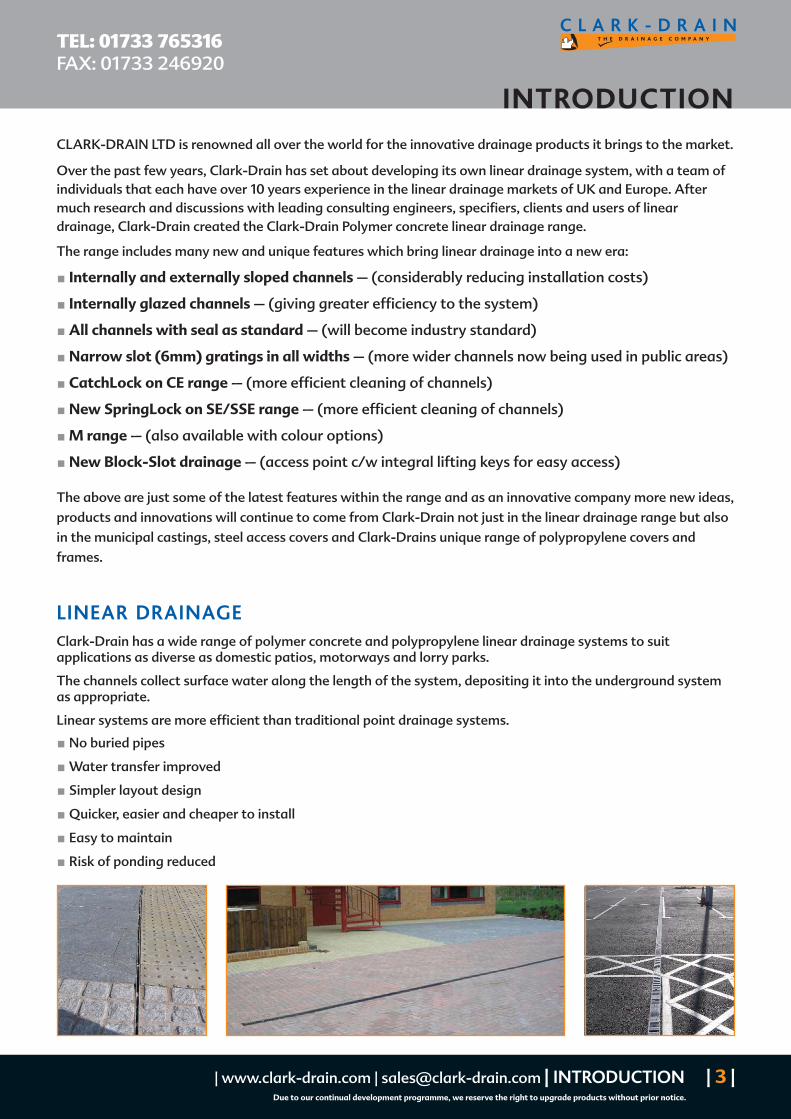
LINEAR DRAINAGE
Clark-Drain has a wide range of polymer concrete and polypropylene linear drainage systems to suitapplications as diverse as domestic patios, motorways and lorry parks.
The channels collect surface water along the length of the system, depositing it into the underground systemas appropriate.
Linear systems are more efficient than traditional point drainage systems.
No buried pipes
Water transfer improved
Simpler layout design
Quicker, easier and cheaper to install
Easy to maintain
Risk of ponding reduced

CLARK-SELF (CD CS10 SERIES)
TEL: 01733 765316FAX: 01733 246920
| 4 | CLARK-SELF (CD CS10 SERIES) | www.clark-drain.com | [email protected]
Due to our continual development programme, we reserve the right to upgrade products without prior notice.
CD CS10.10
CD CS10.12
WEW A-A
DN 100
120
DN70
70
DOMESTIC DRIVEWAY DRAINAGE
CD CS10.10 Polymer Concrete Channel c/w Galvanised Steel SelfLocking Grating.
Including: Male/Female Connections and 110mm Diameter Outlet
External Height: 90mm Internal Height: 80mmExternal Width: 120mm Internal Width: 100mmLength: 100mm Grating Slot Size: 10mm x 80mm
CD CS10.12 Polymer concrete Silt-Box c/w Galvanised Steel SelfLocking Grating and basket.
Length: 500mm Overall depth: 300mm
CD CS10.30 Outlet End Cap c/w Spigot
CD CS10.31 Plain End Cap
*Also available with a narrow slot (6mm) Heelguard grating (CD CS1017)
CLKS 401 GARAGE PACKConsists of: 3 x CLKS 422 channels,1 pair CLKS 402 End Caps,1 x CLKS 403 Debris Trap.
CLKS 422 CLKS 425 CLKS 426
| www.clark-drain.com | [email protected] | CLKS 420 SERIES | 5 |Due to our continual development programme, we reserve the right to upgrade products without prior notice.
CLKS 420 SERIES
TEL: 01733 765316FAX: 01733 246920
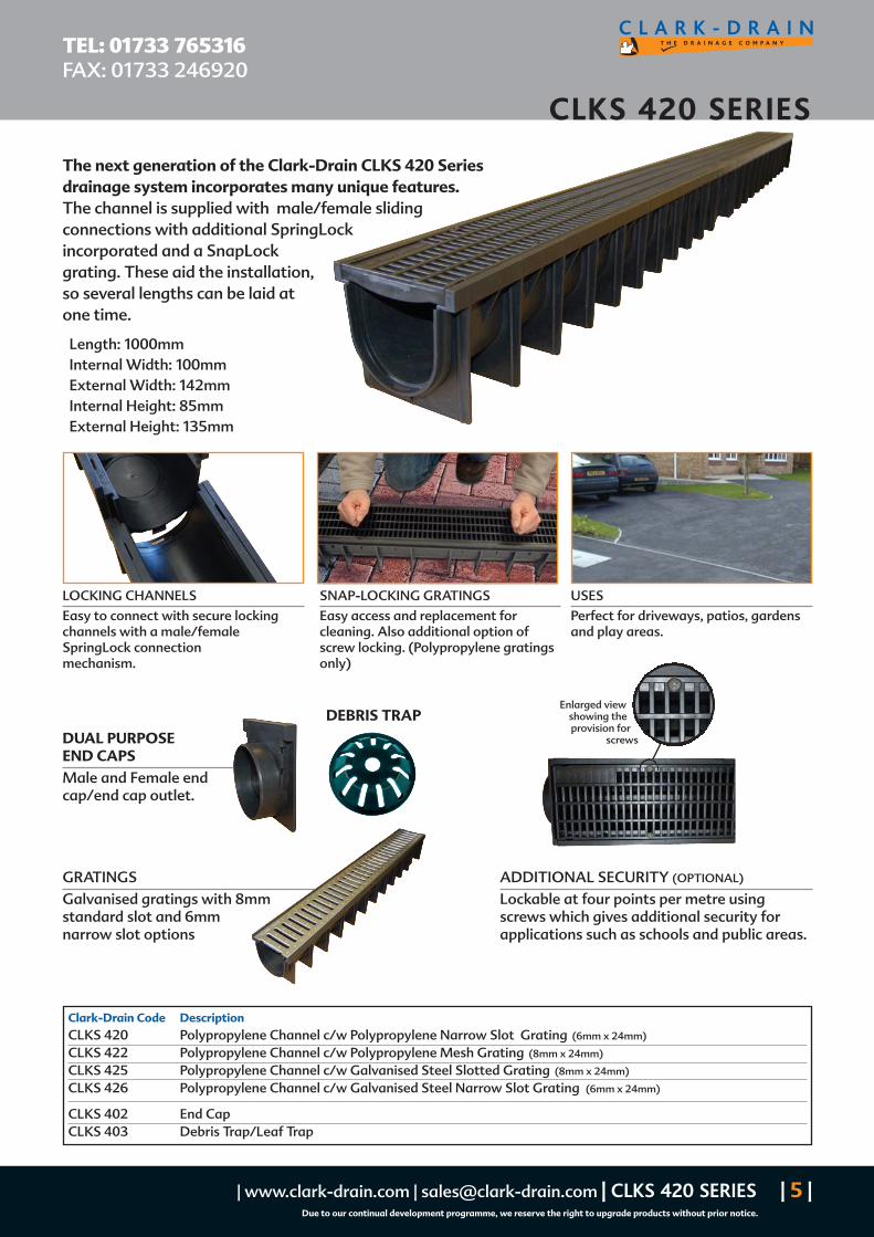
GRATINGSGalvanised gratings with 8mmstandard slot and 6mmnarrow slot options
DUAL PURPOSEEND CAPSMale and Female endcap/end cap outlet.
Clark-Drain Code DescriptionCLKS 420 Polypropylene Channel c/w Polypropylene Narrow Slot Grating (6mm x 24mm)
CLKS 422 Polypropylene Channel c/w Polypropylene Mesh Grating (8mm x 24mm)
CLKS 425 Polypropylene Channel c/w Galvanised Steel Slotted Grating (8mm x 24mm)
CLKS 426 Polypropylene Channel c/w Galvanised Steel Narrow Slot Grating (6mm x 24mm)
CLKS 402 End CapCLKS 403 Debris Trap/Leaf Trap
LOCKING CHANNELS
Easy to connect with secure lockingchannels with a male/femaleSpringLock connectionmechanism.
SNAP-LOCKING GRATINGS
Easy access and replacement forcleaning. Also additional option ofscrew locking. (Polypropylene gratingsonly)
USES
Perfect for driveways, patios, gardensand play areas.
Enlarged viewshowing theprovision for
screws
ADDITIONAL SECURITY (OPTIONAL)
Lockable at four points per metre usingscrews which gives additional security forapplications such as schools and public areas.
The next generation of the Clark-Drain CLKS 420 Seriesdrainage system incorporates many unique features.The channel is supplied with male/female slidingconnections with additional SpringLockincorporated and a SnapLockgrating. These aid the installation,so several lengths can be laid atone time.
Length: 1000mmInternal Width: 100mmExternal Width: 142mmInternal Height: 85mmExternal Height: 135mm
DEBRIS TRAP
CD SE10 SERIES Polymer Concrete Drainage Channels c/w Galvanised Steel Edges
TEL: 01733 765316FAX: 01733 246920
| 6 | CD SE10 SERIES | www.clark-drain.com | [email protected]
Due to our continual development programme, we reserve the right to upgrade products without prior notice.
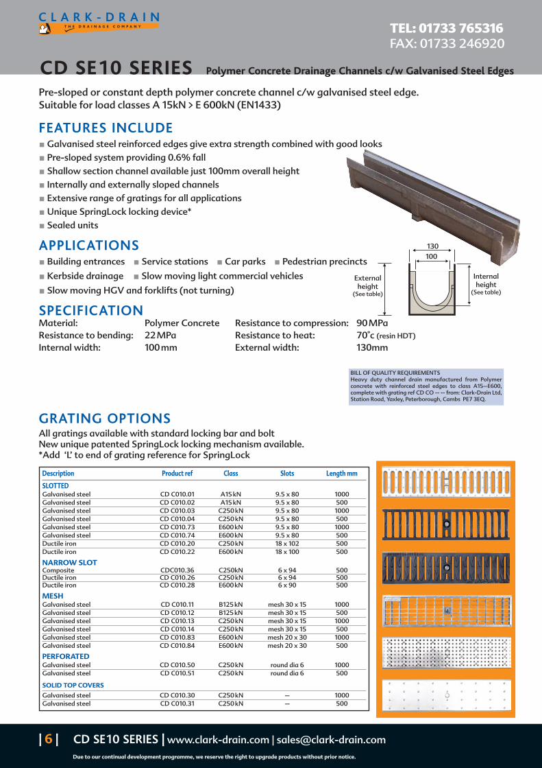
Pre-sloped or constant depth polymer concrete channel c/w galvanised steel edge.Suitable for load classes A 15kN > E 600kN (EN1433)
FEATURES INCLUDE Galvanised steel reinforced edges give extra strength combined with good looksPre-sloped system providing 0.6% fallShallow section channel available just 100mm overall heightInternally and externally sloped channelsExtensive range of gratings for all applicationsUnique SpringLock locking device*Sealed units
APPLICATIONS Building entrances Service stations Car parks Pedestrian precincts
Kerbside drainage Slow moving light commercial vehicles
Slow moving HGV and forklifts (not turning)
SPECIFICATIONMaterial: Polymer Concrete Resistance to compression: 90 MPaResistance to bending: 22 MPa Resistance to heat: 70°c (resin HDT)
Internal width: 100 mm External width: 130mm
100130
Internalheight
(See table)
Externalheight
(See table)
Description Product ref Class Slots Length mm
SLOTTEDGalvanised steel CD C010.01 A15 kN 9.5 x 80 1000Galvanised steel CD C010.02 A15 kN 9.5 x 80 500Galvanised steel CD C010.03 C250 kN 9.5 x 80 1000Galvanised steel CD C010.04 C250 kN 9.5 x 80 500Galvanised steel CD C010.73 E600 kN 9.5 x 80 1000Galvanised steel CD C010.74 E600 kN 9.5 x 80 500Ductile iron CD C010.20 C250 kN 18 x 102 500Ductile iron CD C010.22 E600 kN 18 x 100 500
NARROW SLOTComposite CDC010.36 C250kN 6 x 94 500Ductile iron CD C010.26 C250 kN 6 x 94 500Ductile iron CD C010.28 E600 kN 6 x 90 500
MESHGalvanised steel CD C010.11 B125 kN mesh 30 x 15 1000Galvanised steel CD C010.12 B125 kN mesh 30 x 15 500Galvanised steel CD C010.13 C250 kN mesh 30 x 15 1000Galvanised steel CD C010.14 C250 kN mesh 30 x 15 500Galvanised steel CD C010.83 E600 kN mesh 20 x 30 1000Galvanised steel CD C010.84 E600 kN mesh 20 x 30 500
PERFORATEDGalvanised steel CD C010.50 C250 kN round dia 6 1000Galvanised steel CD C010.51 C250 kN round dia 6 500
SOLID TOP COVERS
Galvanised steel CD C010.30 C250 kN – 1000Galvanised steel CD C010.31 C250 kN – 500
GRATING OPTIONSAll gratings available with standard locking bar and boltNew unique patented SpringLock locking mechanism available.*Add ‘L’ to end of grating reference for SpringLock
BILL OF QUALITY REQUIREMENTSHeavy duty channel drain manufactured from Polymerconcrete with reinforced steel edges to class A15–E600,complete with grating ref CD CO -- -- from: Clark-Drain Ltd,Station Road, Yaxley, Peterborough, Cambs PE7 3EQ.
| www.clark-drain.com | [email protected] | CD SE10 SERIES | 7 |Due to our continual development programme, we reserve the right to upgrade products without prior notice.
Polymer Concrete Drainage Channels c/w Galvanised Steel Edges CD SE10 SERIES
TEL: 01733 765316FAX: 01733 246920
Length Internal Internal External External Area MaximumReference mm height height height upstream height through
upstream mm downstream mm mm downstream mm (cm2) flow (l/s)
CD SE10.H00* 500 92 92 127 127 35 7CD SE10.L00 1000 92 92 127 127 70.5 7CD SE10.01 1000 92 98 127 133 70.6 7CD SE10.02 1000 98 104 133 139 76.4 7.9CD SE10.03 1000 104 110 139 145 82.2 8.9CD SE10.04 1000 110 116 145 151 88.1 9.9CD SE10.05 1000 116 122 151 157 83.9 10.9CD SE10.06 1000 122 128 157 163 99.7 12CD SE10.07 1000 128 134 163 169 105.4 13CD SE10.08 1000 134 140 169 175 111.2 14.2CD SE10.09 1000 140 146 175 181 117 15.3CD SE10.10 1000 146 152 181 187 122.7 16.5CD SE10.H10* 500 152 152 187 187 64.1 17CD SE10.L10 1000 152 152 187 187 128.2 17CD SE10.11 1000 152 158 187 193 128.4 17.7CD SE10.12 1000 158 164 193 199 134.1 18.9CD SE10.13 1000 164 170 199 205 139.9 20.2CD SE10.14 1000 170 176 205 211 145.5 21.5CD SE10.15 1000 176 182 211 217 151.2 22.8CD SE10.16 1000 182 188 217 223 156.9 24.1CD SE10.17 1000 188 194 223 229 162.5 25.5CD SE10.18 1000 194 200 229 235 168.2 26.8CD SE10.19 1000 200 206 235 241 173.8 28.3CD SE10.20 1000 206 212 241 247 179.4 29.7CD SE10.H20* 500 212 212 247 247 92.5 29.7CD SE10.L20 1000 212 212 247 247 185 29.7
Reference Length External Internal Effective Maximummm height mm height mm through through
flow (cm2) flow (l/s)
CD SE10.S00 1000 100 75 50 0.6
SHALLOW CHANNEL FOR USE WHERE THERE IS A DEPTH RESTRICTION
75100
100
130
500
55
0
DN100
DN100
CLARK-DRAIN
130
100500
DN100
DN150
CDSE.S00
Outlet type DN100* l/s DN150* l/s
Horizontal 18 34Trapped 18 34
Trapped and roddable 18 34
SILT-BOX SPECIFICATION (SE10.SB) HYDRAULIC CAPACITIES
*Valid only in optimal conditions using 20–50% safety factor.
*Option for side entry
*NOTE: For end caps see Page 15

CD SSE10 SERIES Polymer Concrete Drainage Channels c/w Stainless Steel Edges
TEL: 01733 765316FAX: 01733 246920
| 8 | CD SSE10 SERIES | www.clark-drain.com | [email protected]
Due to our continual development programme, we reserve the right to upgrade products without prior notice.
Pre sloped or constant depth polymer concrete channel c/w stainless steel edge.Suitable for load classes A 15kN > E 600kN (EN1433)
FEATURES INCLUDE Stainless steel reinforced edges give extra strength combined with good looksPre-sloped system providing 0.6% fallShallow section channel available just 100mm overall heightInternally and externally sloped channelsExtensive range of gratings for all applicationsUnique SpringLock locking device*Sealed units
APPLICATIONS Building entrances Pedestrian precincts
Slow moving light commercial vehicles Internal drainage
Food factories Kitchens Shopping arcades
SPECIFICATIONMaterial: Polymer concrete Resistance to compression: 90 MPaResistance to bending: 22 MPa Resistance to heat: 70°c (resin HDT)
Internal width: 100 mm External width: 130mm
100130
Internalheight
(See table)
Externalheight
(See table)
Description Product ref Class Slots Length mm
SLOTTEDStainless steel CD C010.07 A15 kN 9.5 x 80 1000Stainless steel CD C010.08 A15 kN 9.5 x 80 500Stainless steel CD C010.09 C250 kN 9.5 x 80 1000Stainless steel CD C010.10 C250 kN 9.5 x 80 500Stainless steel CD C010.78 E600 kN 9.5 x 80 1000Stainless steel CD C010.79 E600 kN 9.5 x 80 500
MESHStainless steel CD C010.17 C250 kN mesh 30 x 15 1000Stainless steel CD C010.18 C250 kN mesh 30 x 15 500Stainless steel CD C010.88 E600 kN mesh 20 x 30 1000Stainless steel CD C010.89 E600 kN mesh 20 x 30 500
PERFORATEDStainless steel CD C010.52 C250 kN round dia 6 1000Stainless steel CD C010.53 C250 kN round dia 6 500
SOLID TOP COVERSStainless steel CD C010.32 C250 kN – 1000Stainless steel CD C010.33 C250 kN – 500
GRATING OPTIONSAll gratings available with standard locking bar and boltNew unique patented SpringLock locking mechanism*Add ‘L’ to end of grating reference for SpringLock
BILL OF QUALITY REQUIREMENTSHeavy duty channel drain manufactured from Polymerconcrete with reinforced steel edges to class A15–E600,complete with grating ref CD CO -- -- from: Clark-Drain Ltd,Station Road, Yaxley, Peterborough, Cambs PE7 3EQ.

| www.clark-drain.com | [email protected] | CD SSE 10 SERIES | 9 |Due to our continual development programme, we reserve the right to upgrade products without prior notice.
Polymer Concrete Drainage Channels c/w stainless steel Edges CD SSE10 SERIES
TEL: 01733 765316FAX: 01733 246920
Length Internal Internal External External Area MaximumReference mm height height height upstream height through
upstream mm downstream mm mm downstream mm (cm2) flow (l/s)
CD SSE10.H00* 500 92 92 127 127 35 7CD SSE10.L00 1000 92 92 127 127 70.5 7CD SSE10.01 1000 92 98 127 133 70.6 7CD SSE10.02 1000 98 104 133 139 76.4 7.9CD SSE10.03 1000 104 110 139 145 82.2 8.9CD SSE10.04 1000 110 116 145 151 88.1 9.9CD SSE10.05 1000 116 122 151 157 83.9 10.9CD SSE10.06 1000 122 128 157 163 99.7 12CD SSE10.07 1000 128 134 163 169 105.4 13CD SSE10.08 1000 134 140 169 175 111.2 14.2CD SSE10.09 1000 140 146 175 181 117 15.3CD SSE10.10 1000 146 152 181 187 122.7 16.5CD SSE10.H10* 500 152 152 187 187 64.1 17CD SSE10.L10 1000 152 152 187 187 128.2 17CD SSE10.11 1000 152 158 187 193 128.4 17.7CD SSE10.12 1000 158 164 193 199 134.1 18.9CD SSE10.13 1000 164 170 199 205 139.9 20.2CD SSE10.14 1000 170 176 205 211 145.5 21.5CD SSE10.15 1000 176 182 211 217 151.2 22.8CD SSE10.16 1000 182 188 217 223 156.9 24.1CD SSE10.17 1000 188 194 223 229 162.5 25.5CD SSE10.18 1000 194 200 229 235 168.2 26.8CD SSE10.19 1000 200 206 235 241 173.8 28.3CD SSE10.20 1000 206 212 241 247 179.4 29.7CD SSE10.H20* 500 212 212 247 247 92.5 29.7CD SSE10.L20 1000 212 212 247 247 185 29.7
Reference Length External Internal Effective Maximummm height mm height mm through through
flow (cm2) flow (l/s)
CD SSE10.S00 1000 100 75 50 0.6
CHANNEL FOR USE WHERE THERE IS A DEPTH RESTRICTION
75100
100
130
500
55
0
DN100
DN100
CLARK-DRAIN
130
100
500
DN100
DN150
CDSSE10.S00
Outlet type DN100* l/s DN150* l/s
Horizontal 18 34Trapped 18 34
Trapped and roddable 18 34
SILT-BOX SPECIFICATION (SE10.SB) HYDRAULIC CAPACITIES
*Valid only in optimal conditions using 20–50% safety factor.
*Option for side entry
GRATINGS
CHANNELS
GRATINGS
CHANNELS
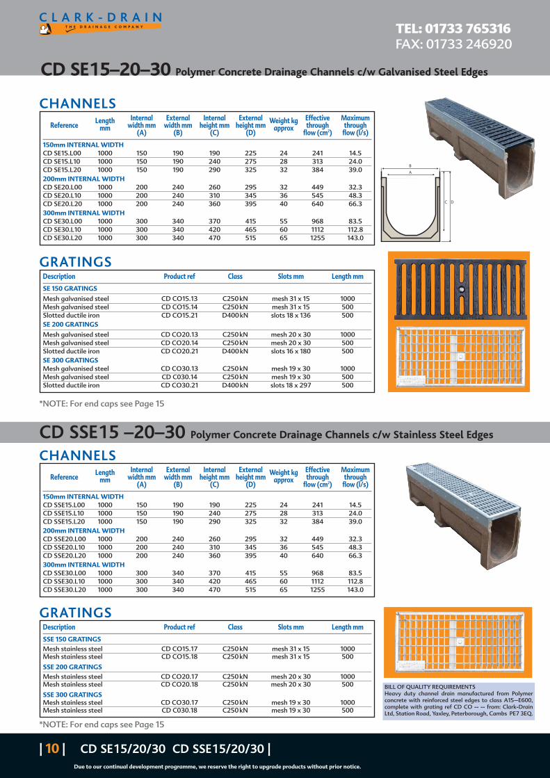
CD SE15–20–30 Polymer Concrete Drainage Channels c/w Galvanised Steel Edges
TEL: 01733 765316FAX: 01733 246920
| 10 | CD SE15/20/30 CD SSE15/20/30 |Due to our continual development programme, we reserve the right to upgrade products without prior notice.
B
A
C D
Length Internal External Internal External Weight kg Effective MaximumReference mm width mm width mm height mm height mm approx through through
(A) (B) (C) (D) flow (cm2) flow (l/s)
150mm INTERNAL WIDTHCD SE15.L00 1000 150 190 190 225 24 241 14.5CD SE15.L10 1000 150 190 240 275 28 313 24.0CD SE15.L20 1000 150 190 290 325 32 384 39.0200mm INTERNAL WIDTHCD SE20.L00 1000 200 240 260 295 32 449 32.3CD SE20.L10 1000 200 240 310 345 36 545 48.3CD SE20.L20 1000 200 240 360 395 40 640 66.3300mm INTERNAL WIDTHCD SE30.L00 1000 300 340 370 415 55 968 83.5CD SE30.L10 1000 300 340 420 465 60 1112 112.8CD SE30.L20 1000 300 340 470 515 65 1255 143.0
Length Internal External Internal External Weight kg Effective MaximumReference mm width mm width mm height mm height mm approx through through
(A) (B) (C) (D) flow (cm2) flow (l/s)
150mm INTERNAL WIDTHCD SSE15.L00 1000 150 190 190 225 24 241 14.5CD SSE15.L10 1000 150 190 240 275 28 313 24.0CD SSE15.L20 1000 150 190 290 325 32 384 39.0200mm INTERNAL WIDTHCD SSE20.L00 1000 200 240 260 295 32 449 32.3CD SSE20.L10 1000 200 240 310 345 36 545 48.3CD SSE20.L20 1000 200 240 360 395 40 640 66.3300mm INTERNAL WIDTHCD SSE30.L00 1000 300 340 370 415 55 968 83.5CD SSE30.L10 1000 300 340 420 465 60 1112 112.8CD SSE30.L20 1000 300 340 470 515 65 1255 143.0
BILL OF QUALITY REQUIREMENTSHeavy duty channel drain manufactured from Polymerconcrete with reinforced steel edges to class A15–E600,complete with grating ref CD CO -- -- from: Clark-DrainLtd, Station Road, Yaxley, Peterborough, Cambs PE7 3EQ.
Description Product ref Class Slots mm Length mm
SE 150 GRATINGS
Mesh galvanised steel CD CO15.13 C250 kN mesh 31 x 15 1000Mesh galvanised steel CD CO15.14 C250 kN mesh 31 x 15 500Slotted ductile iron CD CO15.21 D400 kN slots 18 x 136 500SE 200 GRATINGS
Mesh galvanised steel CD CO20.13 C250 kN mesh 20 x 30 1000Mesh galvanised steel CD CO20.14 C250 kN mesh 20 x 30 500Slotted ductile iron CD CO20.21 D400 kN slots 16 x 180 500SE 300 GRATINGSMesh galvanised steel CD CO30.13 C250 kN mesh 19 x 30 1000Mesh galvanised steel CD C030.14 C250 kN mesh 19 x 30 500Slotted ductile iron CD CO30.21 D400 kN slots 18 x 297 500
Description Product ref Class Slots mm Length mm
SSE 150 GRATINGSMesh stainless steel CD CO15.17 C250 kN mesh 31 x 15 1000Mesh stainless steel CD CO15.18 C250 kN mesh 31 x 15 500
SSE 200 GRATINGSMesh stainless steel CD CO20.17 C250 kN mesh 20 x 30 1000Mesh stainless steel CD CO20.18 C250 kN mesh 20 x 30 500
SSE 300 GRATINGSMesh stainless steel CD CO30.17 C250 kN mesh 19 x 30 1000Mesh stainless steel CD C030.18 C250 kN mesh 19 x 30 500
CD SSE15 –20–30 Polymer Concrete Drainage Channels c/w Stainless Steel Edges
*NOTE: For end caps see Page 15
*NOTE: For end caps see Page 15

| www.clark-drain.com | [email protected] | BLOCK SLOT | 11 |Due to our continual development programme, we reserve the right to upgrade products without prior notice.
Block -Slot Drainage System CD BS10 SERIES
TEL: 01733 765316FAX: 01733 246920
Description Product ref Dimensions
Block Slot Channel c/w 50mm Upstand CD BS10.50 1000 x 130 x 50Block Slot Channel c/w 60mm Upstand CD BS10.60 1000 x 130 x 60Block Slot Channel c/w 85mm Upstand CD BS10.85 1000 x 130 x 856mm Block Slot Channel c/w 85mm Upstand CD BS10.85/6 1000 x 130 x 856mm Stainless Steel Block Slot Channel c/w 85mm Upstand CD BSS10.85/6 1000 x 130 x 85
Access Point - To suit CD BS10.50 CD BS10.50AP 500 x 130 x 50Access Point - To suit CD BS10.60 CD BS10.60AP 500 x 130 x 60Access Point - To suit CD BS10.85 CD BS10.85AP 500 x 130 x 85Access Point - To suit CD BSS10.85 CD BSS10.85AP 500 x 130 x 85
Block Slot Channel c/w 85mm Upstand base width to suit SE15 Channel CD BS15.85 1000 x 180 x 85Block Slot Channel c/w 85mm Upstand base width to suit SE20 Channel CD BS20.85 1000 x 230 x 85Block Slot Channel c/w 85mm Upstand base width to suit SE30 Channel CD BS30.85 1000 x 300 x 85
MEDIUM DUTY (CLASS C250KN)
BLOCK-SLOT DRAINAGE SYSTEM
Channel for overall height, the height of the CD SE10/15/20 or 30 channel to be used needs to be added to theupstand height (see tables on pages 7, 9 and 10)
Slotted drainage channel to suit block-paved areas85mm upstand as standard to suit 65 or 80mm blocks100mm upstand available on requestMetre length available on constant depth or pre-sloped channels500mm access point c/w integral lifting keysAlso available to suit 150 – 200mm wide channels (CD BS15 CD BS20)
128mm 140mm
510mm
452mm
80mm85mm
Channel or Silt-Box
Channel
1000mm
100mm85mm
10mm
85mm
INTEGRALLIFTING KEY

CD CE10 SERIES
TEL: 01733 765316FAX: 01733 246920
| 12 | CD CE10 SERIES | www.clark-drain.com | [email protected]
Due to our continual development programme, we reserve the right to upgrade products without prior notice.
DESCRIPTIONPre-sloped or constant polymer concrete channel c/w ductile iron cast edgerail and ductile iron slotted grating load class F900 kN (EN1433) fixed byCatchLock mechanism. Internal width 100mm and external width 154mm.
All channels are manufactured with a seal as standard.
APPLICATIONS Where very heavy wheel loads are applied such as:
HGV’s Forklifts Military plant etcAreas such as:
Airports Loading bays Industrial areasService stations Service yards Lorry parks
CHANNEL SPECIFICATION
Reference Internal Internal height Internal height External height External height Area Maximum throughlength mm upstream mm downstream mm upstream mm downstream mm (cm2) flow (l/s)
CD CE10.H00* 500 92 92 127 127 35 7CD CE10.L00 1000 92 92 127 127 70.5 7CD CE10.01 1000 92 98 127 133 70.6 7CD CE10.02 1000 98 104 133 139 76.4 7.9CD CE10.03 1000 104 110 139 145 82.2 8.9CD CE10.04 1000 110 116 145 151 88.1 9.9CD CE10.05 1000 116 122 151 157 93.9 10.9CD CE10.06 1000 122 128 157 163 99.7 12CD CE10.07 1000 128 134 163 169 105.4 13CD CE10.08 1000 134 140 169 175 111.2 14.2CD CE10.09 1000 140 146 175 181 117 15.3CD CE10.10 1000 146 152 181 187 122.7 16.5CD CE10.H10* 500 152 152 187 187 64.1 8.5CD CE10.L10 1000 152 152 187 187 128.2 8.5CD CE10.11 1000 152 158 187 193 128.4 17.7CD CE10.12 1000 158 164 193 199 134.1 18.9CD CE10.13 1000 164 170 199 205 139.9 20.2CD CE10.14 1000 170 176 205 211 145.5 21.5CD CE10.15 1000 176 182 211 217 151.2 22.8CD CE10.16 1000 182 188 217 223 156.9 24.1CD CE10.17 1000 188 194 223 229 162.5 25.5CD CE10.18 1000 194 200 229 235 168.2 26.8CD CE10.19 1000 200 206 235 241 173.8 28.3CD CE10.20 1000 206 212 241 247 179.4 29.7CD CE10.H20* 500 212 212 247 247 92.5 29.7CD CE10.L20 1000 212 212 247 247 185 29.8
154
100
Internalheight
(See table)
Externalheight
(See table)
75100
100
154Length Internal External Internal External Effective MaximumReference mm width width height height through through
mm mm mm mm flow (cm2) flow (l/s)
CD CE10.S00 1000 100 154 75 100 50 0.6
CDCE10.S00
CHANNEL FOR USE WHERE THERE IS A DEPTH RESTRICTION
*Option for side entry
*NOTE: For end caps see Page 15

| www.clark-drain.com | [email protected] | SILT-BOX HYDRAULIC CAPACITIES | 13 |Due to our continual development programme, we reserve the right to upgrade products without prior notice.
SILT-BOX HYDRAULIC CAPACITIES CD CE10.SB
GRATING SPECIFICATION
TEL: 01733 765316FAX: 01733 246920
CD CE10 SERIES
Outlet type DN100* l/s DN150* l/s
Horizontal 18 33.9Trapped 18 33.9
Trapped and roddable 18 33.9
154
*Valid only in optimal conditions using 20–50% safety factor.
500
DN100
DN150
500
55
0
DN100
DN100
CLARK-DRAIN
‘CatchLock’ Clark-Drain’s unique Boltless Locking System
Ductile iron class F900 kN slotted gratings c/w CatchLock mechanism.
Reference Slot Length Slot Number IntakeType mm size mm of slots Area cm2
100 SERIESCD CO10.63 Standard 500 13 x 97 15 181CD CO10.69 Narrow 500 6 x 97 15 86
Standard slot(CDCO10.63)
Narrow slot(CDCO10.69)
500MM JUNCTION UNIT

CD CE15/20/30 SERIES
TEL: 01733 765316FAX: 01733 246920
| 14 | CD CE15/20/30 SERIES | www.clark-drain.com | [email protected]
Due to our continual development programme, we reserve the right to upgrade products without prior notice.
External Internal External Effective MaximumReference width (b) height (c) height (d) through through
mm mm mm flow (cm2) flow (l/s)
150mm INTERNAL WIDTH 1000 mm LENGTH
CD CE15.L00 204 190 225 241 14.5CD CE15.L10 204 240 275 313 24CD CE15.L20 204 290 325 384 39
200mm INTERNAL WIDTH 1000 mm LENGTH
CD CE20.L00 254 260 295 449 32.3CD CE20.L10 254 310 345 545 48.3CD CE20.L20 254 360 395 640 66.3
300mm INTERNAL WIDTH 1000 mm LENGTH
CD CE30.L00 354 370 405 968 83.5CD CE30.L10 354 420 455 1112 112.8CD CE30.L20 354 470 505 1255 143
BILL OF QUALITY REQUIREMENTSHeavy duty channel drain CD CE seriesmanufactured from Polymer concrete withductile iron edges and grating to Class F900 kNfrom: Clark-Drain Ltd, Station Road, Yaxley,Peterborough, Cambridgeshire PE7 3EQ.
B
C D
FOR DIMENSIONS SEE TABLE
GRATING SPECIFICATION‘CatchLock’ Clark-Drain’s unique Boltless Locking SystemDuctile iron class F900 kN slotted gratings. c/w CatchLock mechanism.
CHANNEL SPECIFICATIONPre-sloped or constant polymer concrete channel c/w ductile iron castedge rail and ductile iron slotted grating load class F900 kN (EN1433) fixedby CatchLock mechanism.
Reference Slot Length Slot Number IntakeType mm size mm of slots Area cm2
150 SERIESCD CO15.63 Standard 500 13 x 140 16 305CD CO15.69 Narrow 500 6 x 140 16 132
200 SERIESCD CO20.63 Standard 500 13 x 180 16 412CD CO20.69 Narrow 500 6 x 180 16 180
300 SERIESCD CO30.63 Standard 500 17 x 276 17 648CD CO30.69 Narrow 500 6 x 276 17 281
Standard slotCD CO15.63CD CO20.63CD CO30.63
Narrow slotCD CO15.69CD CO20.69CD CO30.69
*NOTE: For end caps see Page 15
| www.clark-drain.com | [email protected] | GULLY ASSEMBLY AND END CAPS | 15 |Due to our continual development programme, we reserve the right to upgrade products without prior notice.
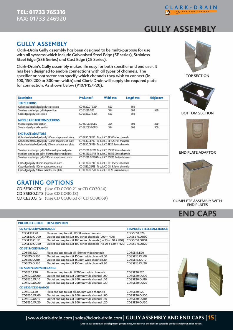
GULLY ASSEMBLY
TEL: 01733 765316FAX: 01733 246920
Description Product ref Width mm Length mm Height mm
TOP SECTIONSGalvanised steel edged gully top section CD SE30.GTS 354 500 550Stainless steel edged gully top section CD SSE30.GTS 354 500 550Cast edged gully top section CD CE30.GTS 354 500 550
MIDDLE AND BOTTOM SECTIONSStandard gully base section CD SE/CE30.GBS 354 500 350Standard gully middle section CD SE/CE30.GMS 354 500 300
END PLATE ADAPTORSGalvanised steel edged gully 100mm adaptor end plate CD SE30.GEP10 To suit CD SE10 Series channelsGalvanised steel edged gully 150mm adaptor end plate CD SE30.GEP15 To suit CD SE15 Series channelsGalvanised steel edged gully 200mm adaptor end plate CD SE30.GEP20 To suit CD SE20 Series channels
Stainless steel edged gully 100mm adaptor end plate CD SSE30.GEP10 To suit CD SSE10 Series channelsStainless steel edged gully 150mm adaptor end plate CD SSE30.GEP15 To suit CD SSE15 Series channelsStainless steel edged gully 200mm adaptor end plate CD SSE30.GEP20 To suit CD SSE20 Series channels
Cast edged gully 100mm adaptor end plate CD CE30.GEP10 To suit CD CE10 Series channelsCast edged gully 150mm adaptor end plate CD CE30.GEP15 To suit CD CE15 Series channelsCast edged gully 200mm adaptor end plate CD CE30.GEP20 To suit CD CE20 Series channels
END PLATE ADAPTOR
BOTTOM SECTION
TOP SECTION
COMPLETE ASSEMBLY WITHEND PLATES
GRATING OPTIONSCD SE30.GTS (Use CD CO30.21 or CD CO30.14)CD SSE30.GTS (Use CD CO30.18)CD CE30.GTS (Use CD CO30.63 or CD CO30.69)
GULLY ASSEMBLYClark-Drain Gully assembly has been designed to be multi-purpose for usewith all systems which include Galvanised Steel Edge (SE series), StainlessSteel Edge (SSE Series) and Cast Edge (CE Series).
Clark-Drain’s Gully assembly makes life easy for both specifier and end user. Ithas been designed to enable connections with all types of channels. Thespecifier or contractor can specify which channels they wish to connect (ie.100, 150, 200 or 300mm width) and Clark-Drain will supply the required platefor connection. As shown below (P10/P15/P20).
PRODUCT CODE DESCRIPTION
CD SE10/CE10/M10 RANGE STAINLESS STEEL EDGE RANGE
CD SE10.E20 Plain end cap to suit all 100 series channels CD SSE10.E20CD SE10.OU00 Outlet end cap to suit 100 series channels (L00 + H00) CD SSE10.OU00CD SE10.OU10 Outlet end cap to suit 100 series channels (no 10 + L10 + H10) CD SSE10.OU10CD SE10.OU20 Outlet end cap to suit 100 series channels (no 20 + L20 + H20) CD SSE10.OU20
CD SE15/CE15 RANGE
CDSE15.E20 Plain end cap to suit all 150mm wide channels CDSSE15.E20CDSE15.OU00 Outlet end cap to suit 150mm wide channel L00 CDSSE15.OU00CDSE15.OU10 Outlet end cap to suit 150mm wide channel L10 CDSSE15.OU10CDSE15.OU20 Outlet end cap to suit 150mm wide channel L20 CDSSE15.OU20
CD SE20/CE20/M20 RANGE
CDSE20.E20 Plain end cap to suit all 200mm wide channels CDSSE20.E20CDSE20.OU00 Outlet end cap to suit 200mm wide channel L00 CDSSE20.OU00CDSE20.OU10 Outlet end cap to suit 200mm wide channel L10 CDSSE20.OU10CDSE20.OU20 Outlet end cap to suit 200mm wide channel L20 CDSSE20.OU20
CD SE30/CE30 RANGE
CDSE30.E20 Plain end cap to suit all 300mm wide channels CDSSE30.E20CDSE30.OU00 Outlet end cap to suit 300mm wide channel L00 CDSSE30.OU00CDSE30.OU10 Outlet end cap to suit 300mm wide channel L10 CDSSE30.OU10CDSE30.OU20 Outlet end cap to suit 300mm wide channel L20 CDSSE30.OU20
END CAPS

CD ’M’ SERIES Monolithic channel and grating for use in carriageways
TEL: 01733 765316FAX: 01733 246920
| 16 | CD ‘M’ SERIES | www.clark-drain.com | [email protected]
Due to our continual development programme, we reserve the right to upgrade products without prior notice.
DESCRIPTION
The Clark-Drain CD ‘M’ Series is the ultimate surface drainage system for heavily trafficked areas, iedistribution centres, highways, docks and airports. Available in 2 widths with various depth options,the system comes as a one piece unit, meaning no separate grating or any other pieces that can belost on site during installation, and no concerns over gratings coming loose whilst being trafficked.The CD ‘M’ Series grating is D400kN as standard with a 13mm wide slot opening to ensure highintake of water in cases of severe down pours and flash flooding, especially important when used inhighway applications.
APPLICATIONS
Distribution centres
Highways
Airports
Docks
Class D400 kN
Complete with side inletAlso available with side inlets for pourous asphalt. For sideinlets add ‘SI’ to the end of the product code.
GRATING COLOUR OPTIONS
TOPS AVAILABLE IN ANY COLOUR WITH RAL REFERENCEFor colour options add the first letter of the colour to the end of the product code. (Example if you requireCDM10D.L00 with a Black top use code: CD M10D.L00B)
Product Description Length Internal Overall Overall Slot Code width width height size
M10 SERIES CHANNELSCD M10D.L00 Polymer concrete channel c/w 2no Class D400kN slotted grating bonded to channel 1000 100 154 212 13CD M10D.L10 Polymer concrete channel c/w 2no Class D400kN slotted grating bonded to channel 1000 100 154 272 13CD M10D.L20 Polymer concrete channel c/w 2no Class D400kN slotted grating bonded to channel 1000 100 154 332 13CD M10D.H00 Polymer concrete channel c/w 1no Class D400kN slotted grating bonded to channel 500 100 154 212 13CD M10D.H10 Polymer concrete channel c/w 1no Class D400kN slotted grating bonded to channel 500 100 154 272 13CD M10D.H20 Polymer concrete channel c/w 1no Class D400kN slotted grating bonded to channel 500 100 154 332 13
M20 SERIES CHANNELSCD M20D.L00 Polymer concrete channel c/w 2no Class D400kN slotted grating bonded to channel 1000 200 254 400 13CD M20D.L10 Polymer concrete channel c/w 2no Class D400kN slotted grating bonded to channel 1000 200 254 450 13CD M20D.L20 Polymer concrete channel c/w 2no Class D400kN slotted grating bonded to channel 1000 200 254 500 13CD M20D.H00 Polymer concrete channel c/w 1no Class D400kN slotted grating bonded to channel 500 200 254 400 13CD M20D.H10 Polymer concrete channel c/w 1no Class D400kN slotted grating bonded to channel 500 200 254 450 13CD M20D.H20 Polymer concrete channel c/w 1no Class D400kN slotted grating bonded to channel 500 200 254 500 13
BLACK TOP NATURAL
CHANNEL C/W SIDE INLETS
Red (R) Yellow (Y) White (W) Black (B) Standard

Product Internal Overall Overall Slot Code Description Length width width height size
ACCESS POINTS
CD M10D.L00 RP Polymer concrete channel c/w 1no Class D400kN slotted grating bonded to channeland 1no removable grating 1000 100 154 212 13
CD M10D.L10 RP Polymer concrete channel c/w 1no Class D400kN slotted grating bonded to channeland 1no removable grating 1000 100 154 272 13
CD M10D.L20 RP Polymer concrete channel c/w 1no Class D400kN slotted grating bonded to channeland 1no removable grating 1000 100 154 332 13
CD M10D.H00 RP Polymer concrete channel c/w 1no removable slotted grating 500 100 154 212 13CD M10D.H10 RP Polymer concrete channel c/w 1no removable slotted grating 500 100 154 272 13CD M10D.H20 RP Polymer concrete channel c/w 1no removable slotted grating 500 100 154 332 13
SILT-BOX
CD M10F.SB CD CE10.SB with upstand to match channelsc/w 1no removable Class F900kN slotted grating 500 100 154 650 13
M20 SERIESACCESS POINTS
CD M20D.L00 RP Polymer concrete channel c/w 1no Class D400kN slotted grating bonded tochannel and 1no removable grating 1000 200 254 400 13
CD M20D.L10 RP Polymer concrete channel c/w 1no Class D400kN slotted grating bonded tochannel and 1no removable grating 1000 200 254 450 13
CD M20D.L20 RP Polymer concrete channel c/w 1no Class D400kN slotted grating bonded tochannel and 1no removable grating 1000 200 254 500 13
CD M20D.H00 RP Polymer concrete channel c/w 1no removable slotted grating 500 200 254 400 13CD M20D.H10 RP Polymer concrete channel c/w 1no removable slotted grating 500 200 254 450 13CD M20D.H20 RP Polymer concrete channel c/w 1no removable slotted grating 500 200 254 500 13
| www.clark-drain.com | [email protected] | M SERIES ACCESS POINTS | 17 |Due to our continual development programme, we reserve the right to upgrade products without prior notice.
ACCESS POINTS AND SILT BOXES
TEL: 01733 765316FAX: 01733 246920
Top view of 1000mm lengthaccess point
CDM10D.L00BRP(1000mm length access point)
CDM10D.H00BRP(500mm length access point)
SILT-BOX
*NOTE: For end caps see Page 15

INSTALLATION PROCEDURE
TEL: 01733 765316FAX: 01733 246920
| 18 | INSTALLATION PROCEDURE | www.clark-drain.com | [email protected]
Due to our continual development programme, we reserve the right to upgrade products without prior notice.
1 It is always recommended that you start at thedischarge/outlet end of the run.
2 Dig a trench for the channel installation withdimensions dependent on the width and height ofthe channel and the load class required (as shownin table).
3 Locate outlet channel, Silt-Box or Gullydependent on which is to be used, pour beddingconcrete and position to proper level andalignment.
4 Install pipe connections and back fill to requiredlevel with concrete.
5 If using pre-sloped channels it is alwaysrecommended that the channels are laid out atthe side of the trench in numerical order prior tolaying.
6 When using constant channel and pre-sloped theconstant channel always comes above the slopedchannel with the same number(ie. No.10 > L10 > No 11).
7 On the bottom of the trench place a bed of
concrete. (Thickness and quality will bedependent on load class required as per Fig A).
8 Lay the channels beginning with deepest first andin numerical order counting down.
9 Fit the channels together by sliding them from topto bottom ensuring no concrete gets in betweenthe joint. Adjust channels for alignment as you go.
10 To complete the run place the closing end cap andseal to the channel.
11 Once the run is complete and end cap in place thefinal surround of concrete can be poured. Theconcrete surround must be finished between2–3mm above the grating surface. It is importantthat the channels are protected against any kindof lateral forces and/or pressures during and afterinstallation and it is therefore recommended thatthe gratings or pieces of wood are placed in thechannels prior to pouring concrete.
12 Once the concrete surround has set, the gratingscan then be installed ensuring all fixings aresecurely fastened.
A A
B
a b Surrounding concrete
Class A 15 kN >8 cm >8 cm 15 N/mm2
Class B 125 kN >10 cm >10 cm 25 N/mm2
Class C 250kN >15 cm >15 cm 25 N/mm2
Class D 400kN >20 cm >20 cm 25 N/mm2
Class E 600kN >20 cm >20 cm 25 N/mm2
Class F 900kN >25 cm >25 cm 25 N/mm2
For F900 kN class installation, you may want to put a wire netting in the
concrete to avoid any cracking due to longitudinal sagging. Using such
netting allows to add transverse reinforcing rods to sustain the channel’s
weight when pouring concrete (as Fig B).
BLOCK PAVINGPaving stones must be 2 – 3mm higher than the upper edge of thechannel.In case of paving stones the first 3 rows of blocks adjacent to thechannels must be bedded in concrete. (as Fig C)
BITUMENThe final coating should be flush with the upper edge of the channel or,even better, should be 2 – 3mm higher than the upper edge of thechannel. (as Fig D)Fig DFig D
Fig C
Fig B
Fig A

| www.clark-drain.com | [email protected] | INSTALLATION PROCEDURE | 19 |Due to our continual development programme, we reserve the right to upgrade products without prior notice.
INSTALLATION PROCEDURE
TEL: 01733 765316FAX: 01733 246920
LATERAL AND LONGITUDINAL EXPANSION JOINTSLongitudinal expansion joints have to be placed approximately every 5 metres and at any junctions. Thesejoints have to be continued into the concrete case (bedding).
A lateral expansion joint should be placed between each face of theconcrete case and the bitumen or concrete paving. These expansionjoints are there to absorb thermic expansions and therefore preventany crushing or destruction of the channel lines. (as shown)
All Clark-Drain channels can be easily accessed for rodding or flushingto maintain their efficiency.
LINEAR DRAINAGE CARE AND MAINTENANCEFREQUENCY OF INSPECTIONIt is not possible to state the frequency of inspections, as it will vary upon the location and environment inwhich the channel is situated. In general the frequency of inspection should be based upon local knowledge.
Inspections should pay particular regard to the condition of the following:
Gratings or covers where fitted Locking for gratings or covers
Sump/gully outlet Concrete surround (where exposed at surface)
Pavement condition adjacent to the channel
MAINTENANCEChannels may be rodded or cleaned with shovels (generally in a direction away from outlet to avoidcontaminating the underground connections)
Ensure gratings (or covers) are relocked into position on completion of maintenance operation. Damagedgratings (or covers) should be replaced.
The locking system (whether removed for cleaning or otherwise) should always be checked for security.Replace any damaged bolts or locking bars.
Remove sump/gully sediment buckets and clean out. Replace bucket before cleaning channel and re-emptyfollowing cleaning of the channel if necessary. Flush sump/gully to ensure it runs freely to undergroundconnections.
Where exposed the concrete haunch should be repaired if damaged. The edge of the channel should not beleft exposed. The level along the haunch should be checked and compared with construction drawings.Deviations from installation drawings may indicate or suggest suspect ground conditions and engineeringadvice may be necessary.
If applicable, joint seals should be repaired or renewed in accordance with manufacturers recommendations.
Steam cleaning agents should not normally be required if maintenance is a regular procedure.
Steam cleaning of polyester and vinylester channels is not recommended.
Longitudal expansion joints 5m
Lateral expansion joints (see table)
Y see table
Y
Y

Clark-Drain LimitedStation Road
Yaxley
Peterborough PE7 3EQ
Telephone: 01733 765316Fax: 01733 246920 Email: [email protected]
Web: www.clark-drain.com
Due to our continual development program we reserve the right to upgrade products without prior notice.
Products must be fitted in accordance with Clark-Drain installation guides.
5413 0807
CLARK-DRAIN PRODUCTS
Galvanised Pressed Steel Covers
Recessed Pavior Range
Internal Recessed Range
Municipal Covers and Frames
Engineering and Agricultural Casting
Special Steel Fabrications
Ducting
Hinged Covers
Upstand and Reservoir Covers (FCW)
Stainless - Brass Covers and Frames
Aluminium Covers and Frames
Security Covers and Frames
Your local stockist


![[3] The Vector Space · 1.Every linear combination is a vector in R3. 2.Every vector in R3 is a linear combination. First statement is easy: every linear combination of 3-vectors](https://static.fdocuments.us/doc/165x107/5fdb995b1105f4691b30e647/3-the-vector-space-1every-linear-combination-is-a-vector-in-r3-2every-vector.jpg)
