Lineage 2000 200-Ampere, 60-Hertz Ferroresonant Rectifier J85503B-2 · 2017-05-05 · Product...
138
Product Manual Select Code 169-790-128 Comcode 107666356 Issue 9 March 2001 Lineage ® 2000 200-Ampere, 60-Hertz Ferroresonant Rectifier J85503B-2
Transcript of Lineage 2000 200-Ampere, 60-Hertz Ferroresonant Rectifier J85503B-2 · 2017-05-05 · Product...

Product ManualSelect Code 169-790-128Comcode 107666356Issue 9March 2001
Lineage® 2000200-Ampere, 60-Hertz
Ferroresonant RectifierJ85503B-2


© 2001 Tyco Electronics Corporation, Harrisburg, PA.All International Rights ReservedPrinted in U.S.A.
Product ManualJ85503B-2Select Code 169-790-128Comcode 107666356Issue 9March 2001
Notice:The information, specifications, and procedures in this manual are subject to change without notice. Tyco Electronics assumes no responsibility for any errors that may appear in this document.
Tyco ElectronicsLineage® 2000
200-Ampere, 60-HertzFerroresonant Rectifier


Tyco Electronics Lineage® 2000 200A Ferroresonant Rectifier J85503B-2
Table of Contents
1 IntroductionGeneral 1 - 1
Applications 1 - 1Features 1 - 1Benefits 1 - 2
Customer Service Contacts 1 - 3Customer Service, Technical Support,
Product Repair and Return 1 - 3Customer Training 1 - 3Warranty Service 1 - 3On-Line Power Systems Product Manuals 1 - 3EasyView Software 1 - 3
2 Product DescriptionGeneral 2 - 1Typical Battery Plant 2 - 1
Battery Plant Subsystems 2 - 1Features 2 - 2
Output Current “Walk-in” 2 - 2Electronic Current Limit 2 - 3Backup Current Limit 2 - 3Selective High Voltage Shutdown 2 - 3Internal Selective High Voltage Shutdown (ISHVSD) 2 - 3Backup High Voltage Shutdown (BUHVSD) 2 - 3Dynamic Response 2 - 3Forced Electronic Load Sharing 2 - 4Safety Interlocks 2 - 4Restart Circuit 2 - 4Output Circuit Breaker 2 - 4Output Current Indication 2 - 4Output Voltage Adjustment Range 2 - 4Float/Equalize/
Boost 2 - 4Equalize Acknowledge 2 - 5Remote Sense Leads 2 - 5Local Sense 2 - 5
Issue 9 March 2001 Table of Contents - 1

Tyco Electronics Lineage® 2000 200A Ferroresonant Rectifier J85503B-2
Remote Shutdown 2 - 5Remote Control Circuit 2 - 5Output Noise 2 - 5Rectifier Failure Alarm (RFA) Test 2 - 6Electromagnetic Compatibility (EMC) 2 - 6
Alarms 2 - 6Load Share Fail (LSF) 2 - 6Fuse Alarms (FA) 2 - 6Rectifier Failure Alarm (RFA) 2 - 6Auxiliary RFA Alarm 2 - 7Charger Fail Alarm (RFA/CFA) 2 - 7Manual Alarm (MAN) 2 - 7AC Fail (ACF) 2 - 7Circuit Breaker Alarm (CB) 2 - 7Phase Monitor Circuit (PHA) 2 - 7Unbalance Alarm Circuit 2 - 8Low Current Alarm (LCA) 2 - 8
Front Panel Controls And Indicators 2 - 8Output Meter 2 - 8Rect V 2 - 9Power Switch 2 - 9Alarms 2 - 9Rect Test Switch 2 - 9Rect + and - Test Jacks 2 - 10Plant + and -Test Jacks 2 - 10Float Adj 2 - 10FLT/EQ 2 - 10Equal Adj 2 - 10Circuit Breaker 2 - 10
Circuit Modules 2 - 10CM1 2 - 11CM2 2 - 11CM3 2 - 11CM4 2 - 11CM5/CM6 2 - 11CM7 2 - 11
Alarm and Control Flow 2 - 12Specifications 2 - 14
2 - Table of Contents Issue 9 March 2001

Tyco Electronics Lineage® 2000 200A Ferroresonant Rectifier J85503B-2
3 Engineering and OrderingRectifier Sizing 3 - 1
Sizing Considerations 3 - 1Sizing Example 3 - 3
Ordering Information 3 - 4Rectifier 3 - 5Hardware 3 - 6Shims 3 - 7Junction Plates 3 - 8
Spare Parts 3 - 8Sample Order 3 - 10Documentation References 3 - 10
4 Safety Safety Precautions 4 - 1ESD Precautions 4 - 3
5 InstallationGeneral 5 - 1Preparing for Installation 5 - 1
Floor Mounting 5 - 1Heat Dissipation 5 - 3AC Input Power 5 - 3DC Output Power 5 - 4DC Power Cables 5 - 6Handling Equipment 5 - 7Installation 5 - 8Unpacking 5 - 8
Installing or Adding a Rectifier 5 - 9Locate and Anchor the Rectifier 5 - 9AC Power Cables 5 - 10DC Power Cables 5 - 10Supplemental Central Office (CO) Ground 5 - 11Plant Control Cable Assembly (Tyco Controller) 5 - 12Plant Control Cable Assembly (External Alarm/Control Bay) 5 - 15
DIP Switch Settings 5 - 16208F Control Board (CM2) 5 - 16323D Digital Meter Board (CM3) 5 - 19329A Fuse Board (CM1) 5 - 19330C Interface Board (CM4) 5 - 19
Converting AC Voltage 5 - 20Initial Battery Charging 5 - 20
Issue 9 March 2001 Table of Contents - 3

Tyco Electronics Lineage® 2000 200A Ferroresonant Rectifier J85503B-2
6 TestingGeneral 6 - 1Precautions 6 - 1Tools and Test Equipment 6 - 2Battery Plant Simulator Test Set 6 - 2Test Load Connection 6 - 3Initial Conditions for Testing Off Line 6 - 5Testing Off Line 6 - 8
Startup 6 - 8Regulation (NL/FL) Test 6 - 8Rectifier Failure Alarm Test 6 - 8Current Limit Test 6 - 9Phase Failure Alarm (PHA) Test 6 - 9Backup High Voltage Shutdown (HVSD) Test 6 - 10Control (TR) Test 6 - 11Selective High Voltage Shutdown (SHVSD) and Restart 6 - 11Float/Equalize Test 6 - 11Local Equalize Control Test 6 - 12Low Current Alarm (LCA) Test (48V only) 6 - 12Load Share Fail (LSF) Test (48V only) 6 - 12Meter Test 6 - 12Off Line Test Completion 6 - 13
Bringing a Rectifier On Line 6 - 13Testing On Line 6 - 15
Regulation (NL/FL) Test 6 - 15Rectifier Failure Alarm/Fuse Alarm Test 6 - 15Current Limit Test 6 - 16Isolated Current Measuring (VI) Test 6 - 16Phase Failure Test 6 - 18Backup High Voltage Shutdown (BUHVSD) Test 6 - 18Control (TR) Test 6 - 19Selective High Voltage Shutdown (SHVSD) and Restart 6 - 20AC Fail Test 6 - 20RFA Circuit Verification RFA Test 6 - 21Meter Test (on line) 6 - 21
Adjust Rectifiers to Float Voltage 6 - 22Adjust Rectifiers Individually 6 - 22Adjust Rectifiers as a Group 6 - 23
Enable and Test Load Share 6 - 24Special Application Load Share (NLS) 6 - 25
4 - Table of Contents Issue 9 March 2001

Tyco Electronics Lineage® 2000 200A Ferroresonant Rectifier J85503B-2
7 Troubleshooting and AdjustmentsGeneral 7 - 1Disconnecting a Rectifier 7 - 1Diagnostics 7 - 3Front Panel Conditions 7 - 6Adjustments 7 - 12
Clear Rectifier Failure Alarm (RFA) 7 - 12Clear Fuse Alarm (FA) 7 - 13Calibrate CM3 Digital Meter 7 - 14Adjust Current Limit 7 - 15
ISHVSD in Plants Without a Controller 7 - 16Restore Rectifier to Service 7 - 18Preventive Maintenance 7 - 19
8 Replacing Components and Circuit ModulesGeneral Considerations for Replacing Components 8 - 1Replacing Components 8 - 4
Thyristors(Q1, Q2) 8 - 5
Diode Heat Sink Assemblies 8 - 6DC Capacitors (C7 through C12) 8 - 6CB1 Circuit Breaker 8 - 7DC Inductor
(L3, L4) 8 - 7Contactor Relay (K1) 8 - 8AC Inductors
(L1, L2) 8 - 8AC Capacitors (C1 - C6,
C13 and C14) 8 - 8Main Transformers
(T1, T2) 8 - 8Handling Circuit Modules 8 - 9Replacing Circuit Modules 8 - 10
CM1 Fuse Board 8 - 10CM2 Control Board 8 - 11CM3 Digital Meter Board 8 - 12CM4 Interface Board 8 - 13CM5 or CM6 Snubber Board 8 - 14CM7 Transformer Board 8 - 14
9 Product Warranty
Issue 9 March 2001 Table of Contents - 5


Tyco Electronics Lineage® 2000 200A Ferroresonant Rectifier J85503B-2
Issue 9 March 2001 List of Figures - 1
List of Figures
Figure 2-1: Block Diagram of a Typical Battery Plant 2 - 2
Figure 2-2: J85503B-2 Control Panel 2 - 8
Figure 2-3: J85503B-2 Rectifier with Door Open 2 - 13
Figure 2-4: Signal Flow Rectifier/Galaxy Controller 2 - 14
Figure 3-1: Recharge Time vs. Recharge Factor 3 - 2
Figure 5-1: Floor Mounting Detail 5 - 2
Figure 5-2: Floor Anchoring 5 - 2
Figure 5-3: AC and DC Termination Points 5 - 5
Figure 5-4: Top View of the J85503B-2 Rectifier 5 - 6
Figure 5-5: DC Output Cables in Cable Rack 5 - 7
Figure 5-6: CM4 Interface Board (330C) 5 - 14
Figure 5-7: 48V DIP Switch Label 5 - 17
Figure 5-8: 24V DIP Switch Label 5 - 18
Figure 6-1: Battery Plant Simulator Test Set 6 - 4
Figure 6-2: CM1 Fuse Board with Clip Connections (Older version of CM1 on the left) 6 - 6
Figure 6-3: CM2 Board with Clip Connections 6 - 7
Figure 7-1: Adjustment Potentiometer on CM3 7 - 15
Figure 8-1: Component Locations 8 - 5


Tyco Electronics Lineage® 2000 200A Ferroresonant Rectifier J85503B-2
List of Tables
Table 2-A: CM2 Circuits 2 - 11
Table 2-B: J85503B-2 Rectifier Specifications 2 - 14
Table 3-A: J85503B-2 Ordering Information 3 - 5
Table 3-B: Hardware Ordering Information 3 - 7
Table 3-C: Shims Ordering Information 3 - 8
Table 3-D: Junction Plates Ordering Information 3 - 8
Table 3-E: Circuit Modules in the J85503B-2 Rectifier 3 - 9
Table 3-F: Spare Fuse Information 3 - 9
Table 3-G: Spare Electrical Parts 3 - 9
Table 5-A: AC Input Requirements 5 - 3
Table 5-B: DC Output Options 5 - 6
Table 5-C: Rack Widths for 350KCMIL Cables 5 - 7
Table 5-D: Controller Connectors 5 - 12
Table 5-E: Control Settings for Initial Battery Charge 5 - 20
Table 6-A: Test Set Connections 6 - 2
Table 6-B: Rectifier Control Settings for Testing Off Line 6 - 5
Table 6-C: Rectifier Control Settings for Testing On Line 6 - 14
Table 6-D: Rectifier Controls for Meter Test On Line 6 - 21
Table 7-A: Troubleshooting 7 - 3
Table 7-B: Front Panel Conditions and Indications 7 - 6
Table 7-C: Alarms on TB1/TB2 of CM4 7 - 8
Table 7-D: Controls on TB1/TB2 of CM4 7 - 9
Issue 9 March 2001 List of Tables - 1

Tyco Electronics Lineage® 2000 200A Ferroresonant Rectifier J85503B-2
Table 7-E: Signals on TB3 of CM4 7 - 10
Table 7-F: Additional Conditions/Indications on the J85503B-2 7 - 11
Table 7-G: Digital Meter Tolerance 7 - 14
Table 7-H: Control Settings Prior to Restoring a Rectifier to Service 7 - 18
Table 8-A: Minimum Torque for Electrical Connections 8 - 3
Table 8-B: Torque and Minimum Yield Strength Values for Mechanical Connections (Using Hex Head Cap Screws) 8 - 4
2 - List of Tables Issue 9 March 2001

Tyco Electronics Lineage® 2000 200A Ferroresonant Rectifier J85503B-2
1 Introduction
General This product manual describes the J85503B-2, 3-phase, 200-ampere, 60-hertz, -48 and ±24 volt, floor-mounted ferroresonant rectifier. The manual covers rectifier technology, features and specifications, installation and testing, and operation and maintenance.
The J85503B-2 rectifier is a member of the Tyco Electronics family of Lineage® 2000 rectifiers. Like all Lineage® 2000 rectifiers, it represents a significant advancement in efficiency, space savings, and serviceability. The rectifier uses the electronically controlled, closed-loop, ferroresonant technology developed by Bell Laboratories. This technology provides excellent output regulation in spite of variations in the incoming commercial line voltage and frequency and the outgoing current or load.
The J85503B-2 rectifier converts commercial 208/240/480-volt ac input power at 60 hertz into highly regulated and filtered, low-noise, -48 and ±24 volt dc output power for telecommunications equipment loads. Central offices usually obtain electrical power from potentially noisy commercial ac lines and/or emergency generators during commercial power failures. The J85503B-2 rectifier provides the high quality dc power required for proper operation of telecommunications equipment.
Applications The J85503B-2 rectifier was developed to support large central office applications where high reliability, low maintenance, long life, and fault tolerance are critical.
Features The J85503B-2 rectifier can be used with a Lineage® 2000 battery plant or any commercial battery plant. It can boost charge
Issue 9 March 2001 Introduction 1 - 1

Tyco Electronics Lineage® 2000 200A Ferroresonant Rectifier J85503B-2
batteries and equalize batteries off-line to 65 volts (for -48-volt plants) or to ±32 volts (for ±24 volt plants), as well as operate without batteries. The rectifier works with Tyco Electronics controllers to provide control and alarm functions. An interface board is available to access these functions with commercial controllers.
Benefits The J85503B-2 rectifier offers you the following:
• Eliminates internal switching transients typically associated with older technologies.
• Reduces noise and transients from the commercial ac source. As the interface between commercial power and telephone equipment, the ferroresonant rectifier significantly attenuates noise and lightning surges from commercial lines.
• Introduces far less noise into closely coupled telephone lines due to lower harmonic components in the input current waveshape.
• Provides highly efficient power conversion.
Ferroresonant technology and the rectifier’s physical design features combine to provide reliable service, easy maintenance, and greater cost-effectiveness.
High reliability: All components in the rectifier meet Tyco Electronics’ strict specifications and reliability standards. The rectifier uses an extremely efficient, free-convection cooling system that keeps components operating at temperatures well below the recommended maximum, which results in high reliability.
Easier maintenance: All circuits for power control, alarms, voltage regulation, current limiting, restart, plant interface, and remote monitoring/control are mounted on replaceable circuit modules. Front access to the circuit modules simplifies replacement or adjustment, if required. Standardized modules simplify parts inventory, resulting in lower costs and better equipment availability.
Wide versatility: The rectifier can be used in a plant with or without batteries and with or without a controller. The load share feature, equalize feature, noise filtering, and interface board adapt the rectifier to practically any application.
1 - 2 Introduction Issue 9 March 2001

Tyco Electronics Lineage® 2000 200A Ferroresonant Rectifier J85503B-2
Customer Service Contacts
Customer Service, Technical Support,Product Repair and Return
For customers in the United States, Canada, Puerto Rico, and the US Virgin Islands, call 1-800-THE-1PWR (1-800-843-1797). Services provided through this contact include initiating the spare parts procurement process, ordering documents, and providing other product and service information.
For other customers worldwide, contact your local field support center or your sales representative to discuss your specific needs.
Customer Training Tyco Electronics offers customer training on many Power Systems products. For information call 1-972-284-2163. This number is answered from 8:00 a.m. until 4:30 p.m., Central Time Zone (Zone 6), Monday through Friday.
Warranty Service For domestic warranty service, contact your Warranty Service Manager (WSM). For international warranty service, contact your sales representative.
On-Line Power Systems Product Manuals
Power Systems on-line product manuals are available athttp://power.tycoelectronics.com/power/lineage.htm
EasyView Software EasyView software is available on-line athttp://power.tycoelectronics.com/software
Issue 9 March 2001 Introduction 1 - 3


Tyco Electronics Lineage® 2000 200A Ferroresonant Rectifier J85503B-2
2 Product Description
General In most telecommunications applications, the output of the rectifier system is electrically connected in parallel with the batteries. The rectifiers provide both the power to the telephone equipment through the plant distribution and the charging and float current to the batteries. In the event of commercial power failure, the batteries supply the required dc power to the telephone equipment. This transition needs no switching because of the parallel connection of the rectifiers and batteries.
Typical Battery Plant
Figure 2-1 shows a basic block diagram of a typical dc battery plant. The battery plant accepts alternating current from the commercial utility or a standby ac power source and rectifies it to produce dc power for the using equipment. The plant’s control and alarm functions interact with the rectifiers and the office. In addition, the plant provides overcurrent protection, charge, discharge, and distribution facilities. Battery reserve automatically provides a source of dc power if the commercial or standby ac fails. This battery reserve is engineered to supply dc power for a specific period of time. In normal practice, battery capacity is sized to provide 3 to 8 hours of reserve time.
Battery PlantSubsystems
AC Input: connects the commercial and/or standby ac power sources to the rectifiers within the plant and provides overcurrent protection. This subsystem is usually supplied by the customer.
Rectifiers: convert an ac source voltage into the dc voltage level required to charge and float the batteries and to power the using equipment.
Issue 9 March 2001 Product Description 2 - 1

Tyco Electronics Lineage® 2000 200A Ferroresonant Rectifier J85503B-2
Controller: provides the local and remote control, monitor and diagnostic functions required to administer the battery plant.
Batteries: provide energy storage for an uninterrupted power feed to the using equipment during loss of ac input or rectifier failure.
DC Distribution: provides overcurrent protection, connection points for the using equipment, and bus bars used to interconnect the rectifiers, batteries, plant shunt, and dc distribution.
Converters: transform -48 volt source voltages into regulated, low-noise 24 volt dc power sources for use with telecommunications loads.
Features The J85503B-2 rectifier offers the following standard features.
Output Current“Walk-in”
This circuit controls the time required for the rectifier to reach its rated output voltage after it is turned on. Initially, the output voltage is about 80 percent of normal, and gradually increases to the required value in approximately 10 seconds. As the output voltage “walks in,” so does output current. This feature minimizes the starting surge on the customer’s power source and is especially important with a more limited power source, such as an engine driven alternator.
Figure 2-1: Block Diagram of a Typical Battery Plant
2 - 2 Product Description Issue 9 March 2001

Tyco Electronics Lineage® 2000 200A Ferroresonant Rectifier J85503B-2
ElectronicCurrent Limit
The rectifier provides a constant output voltage up to its rated output current, at which point it provides constant current. This current limit set point is typically adjustable from 30 to 110 percent of the rectifier rating, 60 to 220 amperes. When the output current tends to increase above the current limit setting, the current limit circuit overrides the voltage regulating signal and limits the output current of the rectifier.
Backup CurrentLimit
In addition to the electronic current limit, the ferroresonant transformers are naturally current limiting to 125 to175 percent of full load, or 250 to 350 amperes.
Selective HighVoltage Shutdown
If the battery voltage goes too high, a Lineage® 2000 controller signals all of the connected rectifiers. This signal causes the rectifier(s) delivering more than 10 percent of full load to shut down. The remaining rectifiers continue to operate. The J85503B-2, 200 ampere also accepts a selective high voltage shutdown (HVSD) signal from any external source via the interface board.
Internal SelectiveHigh Voltage
Shutdown(ISHVSD)
The rectifier will sense a high voltage condition at its output terminals. If delivering more than 10 percent of its rated output, 20 amperes, the rectifier shuts down. This high voltage threshold is user-selectable via programmable DIP switches. The ISHVSD is a backup to the selective HVSD.
Backup HighVoltage Shutdown
(BUHVSD)
This circuit operates if the selective HVSD or ISHVSD fails to operate. The circuit prevents damage to the rectifier or connected equipment in the event of high battery voltage. Each rectifier senses its own output voltage, and when the voltage exceeds a preset value, the rectifier shuts down. The backup high voltage threshold is user-selectable via programmable DIP switches. This circuit operates from an independent voltage source in order to provide improved reliability of the high voltage shutdowns.
DynamicResponse
For any step load change of 10 to 90 percent, or 90 to 10 percent, or a step change of 10 percent of the input voltage, the sense point voltage remains within 5 percent of its setting, and returns and remains in the 1/2 percent band within 300 milliseconds.
Issue 9 March 2001 Product Description 2 - 3

Tyco Electronics Lineage® 2000 200A Ferroresonant Rectifier J85503B-2
For operation without batteries, the sense point voltage remains within 10 percent of its setting and returns and remains in the 2 percent band within 500 milliseconds for any step load change of 50 to 90 percent, or 90 to 50 percent, or a step change of 10 percent of the input voltage.
Forced ElectronicLoad Sharing
The rectifier is equipped with a user selected option by which the rectifier is capable of load sharing with other J85503B-2 rectifiers to better than 10 percent of the full load rating of the rectifier.
Safety Interlocks A series-loop circuit electrically interconnects all of the circuit modules and prevents rectifier operation if any circuit module is not properly installed.
Restart Circuit The rectifier is compatible with the automatic restart features of Lineage® 2000 controllers. The rectifier will also accept an isolated restart signal from any external source via the interface board.
Output CircuitBreaker
An output circuit breaker protects the plant from rectifier malfunction and excessive current, and may be used to disconnect the rectifier from the battery. The standard breaker size is 215 amperes.
Output CurrentIndication
A precision resistor shunt measures the rectifier output current. When used with a Galaxy or Microprocessor Controlled System controller, the rectifier provides an isolated 2- to 10-volt signal, corresponding to a range of no-load to 125 percent of rated output load, to indicate the rectifier drain on the controller. In addition, shunt access points are available on the 329A board for measuring the shunt voltage directly.
Output VoltageAdjustment
Range
The rectifier is capable of providing up to 65 volts dc (or ±32 volts dc in ±24 volt plants) output at 50 percent of its rated output power and nominal input voltage.
Float/Equalize/Boost
The rectifier can be put into the Equalize mode in one of three ways:
2 - 4 Product Description Issue 9 March 2001

Tyco Electronics Lineage® 2000 200A Ferroresonant Rectifier J85503B-2
1. Receiving a signal from a Tyco Galaxy Controller or an MCS Controller equipped with Version 4.0 firmware
2. Putting the front panel switch on the digital meter board in the Equalize position
3. Receiving a closure on the EQL and EQLR terminals of the interface board
EqualizeAcknowledge
In addition to the front panel Equalize LED, an Equalize acknowledge signal (EQA, EQAR) is provided by the interface board. This signal indicates that the rectifier is in the Equalize mode.
Remote SenseLeads
These leads permit the rectifier to regulate the battery voltage by sensing the voltage at the battery. Up to a 2-volt lead drop between the rectifier and battery is permitted. The sense leads are also accessible from the interface board.
Local Sense The rectifier has an option, via user-selected DIP switch settings, to regulate the voltage at the output terminals of the rectifier.
Remote Shutdown The remote shutdown circuit permits the shutdown of a rectifier when the transfer (TR) signal is received from a Tyco controller. When the rectifier is used with a Galaxy or an MCS controller, spare rectifiers can be shut down via the TR signal, resulting in a significant energy saving. The controllers immediately turn the rectifiers back on if they are required to power the load or charge the battery. When not equipped with a Tyco controller, remote shutdown can be accomplished by applying a discharge ground signal to the TR lead on the interface board. When the rectifier is operated without battery, then -48Vdc must also be provided on the BAT lead on the interface board.
Remote ControlCircuit
By connecting to the interface board, the rectifier can be turned on and off remotely. This feature can be enabled or disabled via a switch on the interface board.
Output Noise The output noise is limited to 32 dBrnc. When measured with a Psophometric noise meter, the noise is less than two millivolts
Issue 9 March 2001 Product Description 2 - 5

Tyco Electronics Lineage® 2000 200A Ferroresonant Rectifier J85503B-2
rms. (All of the above requirements are at full load, on battery, and the noise is measured at the battery).
Rectifier FailureAlarm (RFA) Test
A momentary closure either on the Control Board (208F1) or the Interface Board (330C) board simulates a rectifier fail, generates the RFA alarm, but does not shut the rectifier down.
ElectromagneticCompatibility
(EMC)
In regard to radiated and conducted emissions, the J85503B-2 200-ampere rectifier complies with the United States of America Federal Communications Commission (FCC) as required for Class A applications. In addition, the rectifier meets all specified operating characteristics when subjected to electric fields up to 10 volts per meter over a frequency range of 20 to 1000 MHz.
Alarms The J85503B-2, 200 ampere, 60-hertz rectifier can discern the following alarms as well as provide diagnostic information for certain alarms if you use a Galaxy or an MCS controller. When any other controller is used, most of these alarms are available from the interface board of the rectifier.
Load Share Fail(LSF)
In -48 volt plants, the load share circuitry is fused in each rectifier to prevent a failure in one rectifier from cascading into other rectifiers. If this fuse operates, the load share failure LED lights, and the LSF alarm issues. The rectifier continues to provide power with its load share feature automatically disabled. This alarm is not available in ±24 volt plants.
Fuse Alarms (FA) The low-power control circuits, regulation leads, and dc capacitors are fused and alarmed. When any fuse alarm circuit operates, except for the LSF fuse, the rectifier shuts down and the fuse alarm (FA) and rectifier fail alarm (RFA) LEDs light. Tripping the output circuit breaker also generates an FA.
Rectifier FailureAlarm (RFA)
When a rectifier fails, an RFA issues to the controller and the interface board and lights the front panel RFA LED. The rectifier transmits a signal to a Tyco controller, if present, indicating which one of the following has occurred:
2 - 6 Product Description Issue 9 March 2001
Tyco Electronics Lineage® 2000 200A Ferroresonant Rectifier J85503B-2
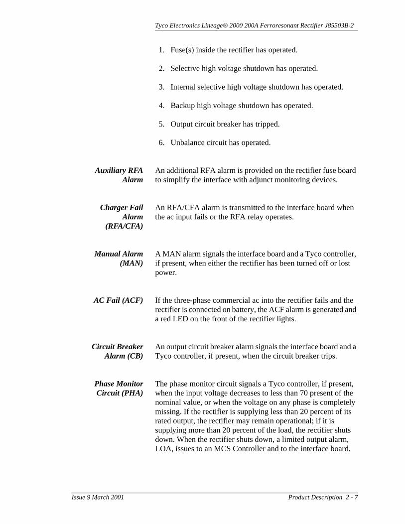
1. Fuse(s) inside the rectifier has operated.
2. Selective high voltage shutdown has operated.
3. Internal selective high voltage shutdown has operated.
4. Backup high voltage shutdown has operated.
5. Output circuit breaker has tripped.
6. Unbalance circuit has operated.
Auxiliary RFAAlarm
An additional RFA alarm is provided on the rectifier fuse board to simplify the interface with adjunct monitoring devices.
Charger FailAlarm
(RFA/CFA)
An RFA/CFA alarm is transmitted to the interface board when the ac input fails or the RFA relay operates.
Manual Alarm(MAN)
A MAN alarm signals the interface board and a Tyco controller, if present, when either the rectifier has been turned off or lost power.
AC Fail (ACF) If the three-phase commercial ac into the rectifier fails and the rectifier is connected on battery, the ACF alarm is generated and a red LED on the front of the rectifier lights.
Circuit BreakerAlarm (CB)
An output circuit breaker alarm signals the interface board and a Tyco controller, if present, when the circuit breaker trips.
Phase MonitorCircuit (PHA)
The phase monitor circuit signals a Tyco controller, if present, when the input voltage decreases to less than 70 present of the nominal value, or when the voltage on any phase is completely missing. If the rectifier is supplying less than 20 percent of its rated output, the rectifier may remain operational; if it is supplying more than 20 percent of the load, the rectifier shuts down. When the rectifier shuts down, a limited output alarm, LOA, issues to an MCS Controller and to the interface board.
Issue 9 March 2001 Product Description 2 - 7

Tyco Electronics Lineage® 2000 200A Ferroresonant Rectifier J85503B-2
Unbalance AlarmCircuit
A severe unbalance developed in the rectifier triggers the rectifier fail circuit. The rectifier shuts down and an alarm is generated. This shutdown of the rectifier has a delay to prevent false operation from transient disturbances, such as may occur during initial turn-on.
Low CurrentAlarm (LCA)
If the forced electronic load share feature is enabled (-48 volt plants only) and any rectifier is providing less than 3 percent of its rating, a low current alarm issues. The alarm issues at 0.5 percent of the rectifier rating and discontinues at 3 percent.
Front Panel Controls And Indicators
Figure 2-2 shows the control panel on front of the J85503B-2, 200-ampere rectifier. The following list describes the controls and indicators on the control panel. Bold letters indicate labels that appear on the control panel or inside the rectifier.
Output Meter The digital Output meter displays the following:
• The rectifier output current when the meter switch is in the Amps position
Figure 2-2: J85503B-2 Control Panel
OutputRect V
Amps
Plt V
RectTest
Adj
Float
FLT
EQ
Equal AdjRect
NL
FL
ALARM
PHA
Power
On
Auto
Off
Plant
FA RFA
ACFLCALSF
Note
In Figure 2-2, “Equal Adj” and “EQ” LEDs may be labeled “Boost” and “BST,” respectively, for international customers.
2 - 8 Product Description Issue 9 March 2001

Tyco Electronics Lineage® 2000 200A Ferroresonant Rectifier J85503B-2
• The rectifier output voltage when the meter switch is in the Rect V position
• The battery voltage when the meter switch is in the Plt V position
Rect V The user may select whether the default position of the meter switch is rectifier current or battery voltage. Otherwise, moving the switch momentarily to the Rect V position displays the rectifier voltage. The user may also select the option of having the meter active when the rectifier is manually turned off.
Power Switch The Power switch turns the rectifier On, Off, or puts it in the Auto mode for remote control via a signal to the interface board. A green LED lights when the rectifier is on.
Alarms The control panel on the J85503B-2 has the following LEDs:
PHA: A red LED lights if the rectifier shuts down due to phase voltages falling below the normal operating range or total loss of a phase
FA: A red LED lights if any fuse, except the LSF fuse, operates or the output circuit breaker operates
RFA: A red LED lights if a failure occurs in the rectifier and the rectifier shuts down
LSF: A yellow LED lights if the fuse in the load share circuit of the rectifier operates
LCA: A yellow LED lights if the load share option is active and the rectifier is providing less than 1.5 amperes of output current. The LED remains on until output reaches 6 amperes.
ACF: A red LED lights if commercial ac fails.
Rect Test Switch The Rect Test switch provides a manual test of the rectifier regulation by simulating a full load (FL) or no load (NL) condition. Operating the switch raises or lowers the output voltage setting of the rectifier by 0.25 volt when on battery. When the switch is in the center position, the rectifier is in the normal operating state; when the switch is operated to FL, the
Issue 9 March 2001 Product Description 2 - 9

Tyco Electronics Lineage® 2000 200A Ferroresonant Rectifier J85503B-2
rectifier goes to maximum current (FL); when it is operated to NL, the rectifier goes to no current.
Rect + and - TestJacks
The Rect + and - test jacks allow for measuring the output voltage of the rectifier.
Plant + and -TestJacks
The Plant + and - test jacks measure the voltage between the points where the remote sense leads are connected. This measurement is accurate only when the remote sense leads are connected.
Float Adj The Float Adj potentiometer provides for manual adjustment of the output float voltage.
FLT/EQ The Float/Equalize, FLT/EQ, switch allows the user to select either the float or equalize operating mode. This switch is disabled when the rectifier is shipped from the factory and must be enabled via S2.1 of the 330C interface board in order to provide the local equalize feature. The yellow equalize LED lights when the rectifier is in the equalize mode.
Equal Adj The Equal Adj potentiometer provides for manual adjustment of the output equalize voltage.
Circuit Breaker The circuit breaker protects the plant from rectifier malfunction and excessive current, and may be used to disconnect the rectifier from the battery. When the circuit breaker trips (midway between On and Off) because of excessive current, an alarm is transmitted to the plant controller. When the circuit breaker is manually turned off, no alarm is transmitted.
Circuit Modules The rectifier’s signal processing and control circuitry are located on replaceable circuit modules or packs. Circuit modules are plug-in boards that are ordered separately. (See Section 3 for ordering information.) All modules are accessible by opening the rectifier door. Figure 2-3 shows the location of the modules and other features of the rectifier. Figures 6-2, 6-3, 7-1, and 5-6 show the CM1 through CM4 board layouts, respectively. A description of each module follows.
2 - 10 Product Description Issue 9 March 2001

Tyco Electronics Lineage® 2000 200A Ferroresonant Rectifier J85503B-2
CM1 The CM1 circuit module (329A Fuse Board) protects the control circuits from faults in the rectifier power train. It contains alarm fuses, bleeder resistors, access points for the plant shunt voltage, and an isolated RFA transfer contact.
CM2 The CM2 circuit module (208F1 Control Board) contains the following circuits:
CM3 The CM3 circuit module (323D Digital Meter Board) controls the digital Output meter and all indicators on the rectifier control panel. The meter displays the rectifier’s output current, voltage, or the plant battery voltage, depending on the position of the selector switch. See Figure 2-2.
CM4 The CM4 circuit module (330C Interface Board) provides alarm and control circuitry that permits the rectifier to interface with various controllers. It also provides additional monitoring points and new alarm interface points for AC fail, RFA test, load share, LCA, and LSF.
CM5/CM6 The CM5 and CM6 circuit modules are identical boards, ED83156-30 Group 3. These boards contain a triac/thyristor snubber network and EMI circuitry. Refer to schematic drawing SD83281-01 for further information.
CM7 The CM7 circuit modules (425C and 425D Transformer Boards) contain the sense transformer, bleeder resistors, and walk-in reset relay. Use of these boards depends upon ac input voltage.
Table 2-A: CM2 Circuits
Local power supplies Restart feature
Feedback regulator Unbalance shutdown
Walk-in feature Fuse alarm
Backup high voltage shutdown Electronic current limit
Remote shutdown Output current isolation circuit
Manual on/off relay Load share circuit
Phase monitor RFA test
Rectifier portion of external selective high voltage shutdown
Issue 9 March 2001 Product Description 2 - 11

Tyco Electronics Lineage® 2000 200A Ferroresonant Rectifier J85503B-2
Alarm and Control Flow
The J85503B-2 200-ampere rectifier is typically installed in a battery plant that is monitored and controlled by a Tyco Lineage® 2000 controller. The rectifier generates various monitoring and alarm signals and, in this type of installation, sends them to the controller for processing and subsequent action. The action may be local or remote alarm indications or control signals fed back to the rectifier. Refer to the various controller product manuals for a description of rectifier signal processing and resultant action.
Figure 2-4 shows the typical signal flow between a rectifier and a Galaxy controller. The control signals and alarms enter and leave the rectifier via the interface board, CM4. When used with a non-Tyco controller or if additional monitoring is desired, interface to TB1, TB2, and TB3 of the 330C interface board. The plant controllers also use replaceable circuit modules.
Warning
Circuit modules must not be connected or disconnected with voltages present. Personal injury or equipment damage may occur. See Section 8 for how to replace circuit modules.
2 - 12 Product Description Issue 9 March 2001

Tyco Electronics Lineage® 2000 200A Ferroresonant Rectifier J85503B-2
Figure 2-3: J85503B-2 Rectifier with Door Open
CM1 FuseBoard 329A
CM4 InterfaceBoard 330C
CM3 DigitalMeter Board323D
CM2 ControlBoard 208F1
CM5 and CM6Snubber BoardsED83156-30 G3(Mounted on Side Wall)
CM7 TransformerBoard 425C, D, or F
CB1 CircuitBreaker225 Amperes
Main TransformerBehind Cover Plate
Issue 9 March 2001 Product Description 2 - 13

Tyco Electronics Lineage® 2000 200A Ferroresonant Rectifier J85503B-2
.
Refer to the appropriate controller J drawing to order cable assemblies for other Galaxy configurations, the ECS-6U, ECS-12U, the MCS, and the CCS controllers.
Specifications Table 2-B provides electrical and physical characteristics for the J85503B-2 rectifier.
Figure 2-4: Signal Flow Rectifier/Galaxy Controller
GalaxyController
Plant Control Cable AssemblyH285226 G-60
DC Output Circuit Breaker Status (CB)
RFA Test
Load Share Fail (LSF)
AC Fail (ACF)
Low Current Alm (LCA)
Power Switch Status (MAN)
Rectifier Shutdown (TR)
Rectifier Current Capacity (TP)
Rectifier Failure Alarm (RFA)
Rectifier Restart (RS)
Rectifier Current Drain (VI)
Rectifier Efficiency Algorithm (TRH)
Phase Failure Alarm (PHA)
Rectifier Regulation (R+, R–)
CM4Interface
Board330C
Rectifier
Table 2-B: J85503B-2 Rectifier Specifications
Nominal Output Voltage 52 volts dc or 24 volts dc
Operating Output Voltage Ranges 48 - 65 volts dc or 24 - 32 volts dc
Operating Frequency Range 57 - 63 Hz
Output Current 0 - 200 amperes (Note 1)
Nominal Input Voltage 208/240/480/416 volts ac
Input Voltage Ranges184 - 220 volts ac212 - 254 volts ac422 - 509 volts ac
Input Current
± 24V18179
-48V38 amperes @ 208 volts ac (Note 2)32 amperes @ 240 volts ac (Note 2)17 amperes @ 480 volts ac (Note 2)
Efficiency 88% typical (Note 2)
2 - 14 Product Description Issue 9 March 2001

Tyco Electronics Lineage® 2000 200A Ferroresonant Rectifier J85503B-2
Notes for Table 2-B:
1. Can operate at 220 amperes output for periods shorter than 8 hours.
2. Measured at 54 volts or 27 volts under full load.
3. Measured on 800 ampere-hour battery with a 0.5-volt lead drop.
4. At full load measured at battery.
5. For altitudes above 1524 meters, derate the temperature by 2 degrees Celsius per 305 meters.
Regulation on Battery ±0.5%Regulation off Battery ± 2% AC Ripple 50 millivolts peak to peak (Note 3)Output Noise (On Battery)Psophometric Noise
< 46 dBrnc< 32 dBrnc (Note 3)< 2 mV rms (Note 4)
Load Share Accuracy ±20 amperesHeat Dissipation 3700 BTU/hr (1100 watts) (Note 2)Power Factor >0.97 at full loadHumidity Rating 10 - 95% non-condensingOperating Altitude Sea level to 3048 meters (Note 5)
Operating Temperature0 - 35° C (Lists 1, 2, 3, 4, 5, 6)0 - 50° C (Lists 1, 2, 3, 4, 5, 6 at 150A output)
Audible Noise <65 dBAEarthquake rating Zone 4 per Bellcore TR-EOP-000063Width 330.2 mm (13 inches)Height 1817.6 mm (71.56 inches)Depth 393.7 mm (15.5 inches)
Table 2-B: J85503B-2 Rectifier Specifications
Issue 9 March 2001 Product Description 2 - 15


Tyco Electronics Lineage® 2000 200A Ferroresonant Rectifier J85503B-2
3 Engineering and Ordering
Rectifier Sizing This section discusses how to determine the minimum number of rectifiers required in a battery plant. Rectifiers of different output current capacities can be paralleled in a plant; therefore, size mixing is also discussed.
SizingConsiderations
Any time the plant load exceeds the combined capacity of the rectifiers, the batteries, which are in parallel, must discharge in order to supply the additional current demand. Momentary discharges are handled easily by the batteries; in fact, this capability precludes the need for the rectifiers to handle infrequent, momentary peak current conditions. However, the total rectifier capacity of the plant must be designed to meet prolonged periods of current drain during “busy” demand times. In a telecommunications environment, this is known as the “average busy hour” (abh) current drain. It is defined as the average busy hour of busy season current drain drawn at normal plant operating voltage.
Other parameters which the customer must decide are the maximum length of time the batteries are allowed to discharge (reserve time), and the amount of time allowed for recharge of the batteries (recharge time). These two times are used in determining the “recharge factor” from battery data similar to that shown in Figure 3-1. The recharge factor determines the amount of current required, over and above the load demand, to recharge the batteries concurrently with supplying the abh load demand.
Issue 9 March 2001 Engineering and Ordering 3 - 1

Tyco Electronics Lineage® 2000 200A Ferroresonant Rectifier J85503B-2
Figure 3-1 illustrates some general bounds on sizing rectifiers for recharging batteries. With other conditions fixed, it illustrates three generalities.
As the reserve time of batteries increases, so does the recharge factor required for a given recharge time.
Some minimum recharge factor is required to effectively recharge the batteries.
Continuing to increase the recharge factor will not materially reduce the recharge time.
Redundant and non-redundant systems
The recharge factor (1.2 to 1.6) multiplied by the abh current drain gives the minimum installed rectifier capacity (mirc) for any plant.
mirc = abh x recharge factor
The mirc is also the sum of the abh and the recharge current. For example, a 1.2 recharge factor in a plant with an abh current drain of 100 amperes simultaneously allows 100 amperes for plant load, and 20 amperes for battery recharge in 24 hours, following a 3-hour discharge period.
M
Figure 3-1: Recharge Time vs. Recharge Factor
1.012 16 20 24 28 32 36 40 44 48
Hours to 95% Charge
Rec
harg
eF
acto
r
1.1
1.2
1.3
1.4
1.5
1.6 34 Hours Reserve5678
3 - 2 Engineering and Ordering Issue 9 March 2001

Tyco Electronics Lineage® 2000 200A Ferroresonant Rectifier J85503B-2
The mirc value of current is a requirement of either a redundant or a non-redundant rectifier system. It is the only requirement defining a non-redundant system. A redundant system additionally requires that the loss of any one rectifier does not cause the remaining rectifier capacity to fall below the abh value. This is another way of saying that the loss of any one rectifier in the system does not cause the batteries to discharge. In some cases, meeting the mirc current requirement also meets the additional requirement for a redundant system; in other cases it does not.
Sizing Example The following examples illustrate the sizing principles given above.
1. The average busy hour current (abh) of a plant is 2850A. The plant is required to have a 4-hour reserve (discharge) time and a 24-hour recharge time. Calculate the minimum installed rectifier capacity (mirc) and the number of 200A rectifiers required in redundant and non-redundant systems.
From Figure 3-1, a 24-hour recharge time intersects the 4-hour reserve curve at a recharge factor of approximately 1.2.
mirc = abh x recharge factor
mirc = 2850A x 1.2 = 3420A
The number of 200A rectifiers required to supply at least 3420A is nine (9 x 200A = 3600A). Nine rectifiers are required in a non-redundant system. If one of the rectifiers fails, the remaining rectifier capacity is 3200A (8 x 200A), which is greater than the 2850A abh. Therefore, nine 200A rectifiers are also sufficient for a redundant system.
2. The average busy hour current drain (abh) of a plant is 210A. The plant is required to have an 8-hour reserve time and a 24-hour recharge time. Calculate the mirc and the number of 100A rectifiers required in redundant and non-redundant systems.
From Figure 3-1, a 24-hour recharge time intersects the 8-hour reserve curve at a recharge factor of approximately 1.38.
Issue 9 March 2001 Engineering and Ordering 3 - 3

Tyco Electronics Lineage® 2000 200A Ferroresonant Rectifier J85503B-2
mirc = abh x recharge factor
mirc = 210A x 1.38 = 290A
The number of 100A rectifiers required to supply at least 290A is three (3 x 100 = 300A). Three rectifiers are required in a non-redundant system. If one of the rectifiers fails, the remaining rectifier capacity is 200A (2 x 100A), which is less than the 210A abh. Therefore, at least one more 100A rectifier is required for a redundant system (four 100A rectifiers total). If one fails, 300A capacity remains, which is greater than the 210 abh.
Note that in this example, the redundant system could also be realized by either of the following combinations of rectifiers:
– One 200A and three 100A rectifiers– Two 200A and one 100A rectifiers
As long as the loss of any one rectifier does not leave a remaining capacity of less than 210 amperes, the system is redundant.
Ordering Information
The J85503B-2 rectifier is ordered using the List (L) numbers and tables on the equipment drawing and has six main configurations based on different input/output voltage options.
• List 1 provides a rectifier with a 208 volt ac input and a 24 volt dc output.
• List 2 provides a rectifier with a 208 volt ac input and a 48 volt dc output.
• List 3 provides a rectifier with a 240 volt ac input and a 24 volt dc output.
• List 4 provides a rectifier with a 240 volt ac input and a 48 volt dc output.
• List 5 provides a rectifier with a 480 volt ac input and a 24 volt dc output.
• List 6 provides a rectifier with a 480 volt ac input and a 48 volt dc output.
Other lists on the J85503B-2 drawing are ordered as “Equipped With” items. This means that they are ordered in addition to a main list and will be assembled in the factory.
3 - 4 Engineering and Ordering Issue 9 March 2001
Tyco Electronics Lineage® 2000 200A Ferroresonant Rectifier J85503B-2
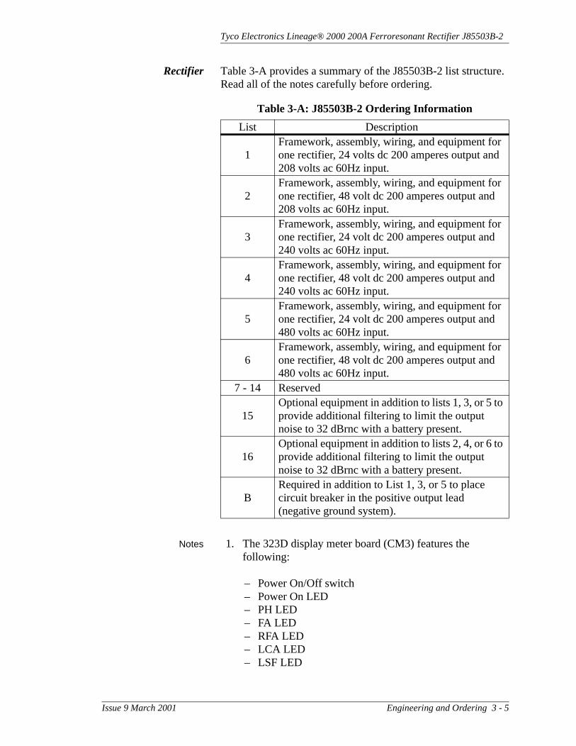
Rectifier Table 3-A provides a summary of the J85503B-2 list structure. Read all of the notes carefully before ordering.
Notes 1. The 323D display meter board (CM3) features the following:
– Power On/Off switch– Power On LED– PH LED– FA LED– RFA LED– LCA LED– LSF LED
Table 3-A: J85503B-2 Ordering Information
List Description
1Framework, assembly, wiring, and equipment for one rectifier, 24 volts dc 200 amperes output and 208 volts ac 60Hz input.
2Framework, assembly, wiring, and equipment for one rectifier, 48 volt dc 200 amperes output and 208 volts ac 60Hz input.
3Framework, assembly, wiring, and equipment for one rectifier, 24 volt dc 200 amperes output and 240 volts ac 60Hz input.
4Framework, assembly, wiring, and equipment for one rectifier, 48 volt dc 200 amperes output and 240 volts ac 60Hz input.
5Framework, assembly, wiring, and equipment for one rectifier, 24 volt dc 200 amperes output and 480 volts ac 60Hz input.
6Framework, assembly, wiring, and equipment for one rectifier, 48 volt dc 200 amperes output and 480 volts ac 60Hz input.
7 - 14 Reserved
15Optional equipment in addition to lists 1, 3, or 5 to provide additional filtering to limit the output noise to 32 dBrnc with a battery present.
16Optional equipment in addition to lists 2, 4, or 6 to provide additional filtering to limit the output noise to 32 dBrnc with a battery present.
BRequired in addition to List 1, 3, or 5 to place circuit breaker in the positive output lead (negative ground system).
Issue 9 March 2001 Engineering and Ordering 3 - 5

Tyco Electronics Lineage® 2000 200A Ferroresonant Rectifier J85503B-2
– ACF LED– Equalize LED– Rectifier volts/Rectifier amperes/Plant voltage display
selection switch– NL/FL test switch– Float/Equalize switch– Output adjust potentiometer– Equalize potentiometer– Pin jacks for external meter
2. Adding the 330C Auxiliary Interface Board (CM4) to a 323D Digital Meter Board provides these additional features:
– The digital meter can be set to display either the output current or the plant voltage.
– The 330C monitors CFA/RFA, RFA, CB, LOA, EQA and MAN conditions. It also provides access to RM24, RM48, R+, R-, RS, RSR, TR, TRR, BAT, GND, HV, EQL, and EQLR.
– Switches on the 330C enable or disable remote control capability, maintain the meter indication while the unit is off, and enables or disable the front panel equalize switch.
– The power ON/AUTO/OFF switch enables or disables the remote control feature.
3. The standard output filter provided with Lists 1, 2, 3, 4, 5 and 6 meets Bell standard TR-EOP-000151 Issue 1 for output noise levels up to 44 dBrnc. The optional output filter (List 15 or 16) meets GTE standard GTS 8336 Issue 2 for output noise levels of 32 dBrnc for an on-battery condition only when measured at the battery position.
Hardware 4. The following items must be ordered from Table 3-B:
– ac input connectors– frame ground connector– dc output connectors
5. The central office ground connector and the mounting anchor bolts (kit) are not provided with the rectifier. Order these items from Table 3-B.
3 - 6 Engineering and Ordering Issue 9 March 2001

Tyco Electronics Lineage® 2000 200A Ferroresonant Rectifier J85503B-2
Use approved tooling for crimping connectors.
6. The standard output circuit breaker provided with Lists 1, 2, 3, 4, 5 and 6 is a 225 ampere breaker and meets Bellcore standard TR-EOP-000151 issue 1 for output protection.
7. When installing J85503B-2 rectifiers in a plant with other Tyco Lineage® 2000 rectifiers, cut lead 13 of the interface cable of all the rectifiers not equipped with an equalize feature to prevent the J85503B-2 rectifier from being placed permanently in an equalize mode of operation.
8. When lifting the rectifier from the top, use and install four 5/8-11 eyebolts (MacMaster Carr #3014T52) and four hex nuts (comcode 841063670).
Shims 9. Order shims for leveling the rectifier, as required. See Table 3-C.
Table 3-B: Hardware Ordering Information
Equipment Requirement Qty Description ComcodeAnchor Bolts (Kit) Zone 3 or 4 1 H569-407 G-6 847320835
Anchor Bolts (Kit) Zone 0, 1, or 2 1 H569-407 G-1 847135654
DC Output Connectors
4/0 AWG Class B 4 WP91412 L-59 405348251
DC Output Connectors
4/0 AWG Flex 4 WP91412 L-27 405347923
DC Output Connectors
350KCMIL Class B
4 WP91412 L-61 405348277
DC Output Connectors
350 KCMIL AWG Flex
4 WP91412 L-86 406021915
CO Ground Connectors
Class B 1 WP91412 L-54 405348202
CO Ground Connectors
Flex 1 WP91412 L-8 405347683
AC Input List 1, 3, 5, 6
10 AWG Strd 3 WP91412 L-93 406338145
AC Input List 2, 4 6 AWG Strd 3 WP91412 L-171 407334671
AC EG Connector 10 AWG Strd 1 WP91412 L-73 405356171
Issue 9 March 2001 Engineering and Ordering 3 - 7

Tyco Electronics Lineage® 2000 200A Ferroresonant Rectifier J85503B-2
Junction Plates 10. Order installation mounting plates (junction plates) for side-to-side or front-to-back support at the top of adjacent rectifiers from Table 3-D.
11. If local codes permit, you may connect an overhead raceway to the rectifier with flex steel conduit. Flex steel conduit kit (846860682) comes complete with 17 inches of 1-1/4 inch diameter flex steel conduit, two KS20785 L-39 connectors, and two KS20785 L-114 insulating bushings.
12. Use the cable ties provided with the plant to secure the plant control cable to the top frame vertical post. The control cable should pass through the spiral wrap to the door where it is mounted with push-in tie wraps. You must secure a tie wrap to the control cable just above the top lid grommet so that the control cable cannot enter the rectifier cabinet. Do not, under any circumstance, roll the control cable up inside the rectifier. Roll up any extra length of control cable and tie it up at the controller.
13. The J85503B-2 -48 volt rectifier is capable of forced load share with other J85503B-2 rectifiers.
Spare Parts The circuit modules described in Section 2 can be ordered as spare parts kits (K1, K2, or K3). Each kit has the same packs except for CM7, which is dependent on the J-List. Table 3-E shows the contents of the kits along with the part numbers to order modules individually.
Table 3-C: Shims Ordering Information
Thickness Comcode0.063 inch 8424398610.125 inch 8424398790.250 inch 842439887
Table 3-D: Junction Plates Ordering Information
Type ComcodeSide-to-side 848204640
Front-to-back (2 or 4 rectifiers)
848204657
Bolt to secure plates 804220838
3 - 8 Engineering and Ordering Issue 9 March 2001

Tyco Electronics Lineage® 2000 200A Ferroresonant Rectifier J85503B-2
Table 3-E: Circuit Modules in the J85503B-2 Rectifier
Kit - J85503C-3
J-ListCircuit
ModulesApparatus
CodeComcode Description
List K1 1 or 2 CM7 425C 107134454 Transformer BoardList K2 3 or 4 CM7 425D 107134462 Transformer BoardList K3 5 or 6 CM7 425F 107134488 Transformer Board
List K1-K3List 1
through 6
CM1 329A 106295280 Fuse BoardCM2 208F1 107199184 Control BoardCM3 323D 106938137 Digital Meter BoardCM4 330C 107199192 Interface Board
CM5 and CM6
ED83156-30 G-3
601326408 Snubber Board
Table 3-F: Spare Fuse Information
Reference Designation
Part Number Rating Vendor Comcode
F1, F2, F3, F4, F5 FLM-30 30 amperes LittlefuseTM 406392290F1, F2, F3 alarm fuses
on CM1WP90247 L-3 1/2 ampere SAN-OTM 405673161
F1 on CM2 WP90247 L-10.18
ampere SAN-OTM 405373002
Table 3-G: Spare Electrical Parts
Reference Designation Comcode Part NumberDiodes CR1 - CR4 405934449 WP91147 L-8 BSR
Triacs Q1 - Q2 406912816BTA40-800B
(SGS-Thomson Microelectronics)
AC capacitors C1 - C4 40618268H62R6630E
(AerovoxTM)DC capacitors C5 - C9 406962753 KS20133 L-14
Issue 9 March 2001 Engineering and Ordering 3 - 9

Tyco Electronics Lineage® 2000 200A Ferroresonant Rectifier J85503B-2
Sample Order This sample order is for a 200-ampere, 48 volt, 60 Hz rectifier with a 208 vac input. It includes a filter for limiting the output noise to 32 dBrnc, and a cable for connection to a Galaxy controller.
Documentation References
The following documents provide the engineering, ordering, and installation information for the Tyco Lineage® 2000 200A ferroresonant rectifier.
Supplementary information on Tyco controllers may be found in the following documents.
Sample Order
Item Qty Description
1 1J85503B-2 L-2 200 Amp, 48V Rectifier E/W L-16
2 1 H285-225 G-60Cable Assembly“A” Dim = __ ft. lg.
Lineage® 2000 200A, 60 Hz Rectifier
Assembly and Ordering Drawing J85503B-2
Wiring Diagram T83281-30
Schematic Drawing SD83281-01
Product Manual Select Code 169-790-128
Galaxy Controller
Assembly and Ordering Drawing J85501F-1
Wiring Diagram T83217-30
Schematic Drawing SD83217-01
Product Manual Select Code 167-790-060
Galaxy Remote Peripheral Monitoring System
Assembly and Ordering Drawing J85501G-1
Wiring Diagram T83275-30
Schematic Drawing SD83275-01
Product Manual Select Code 167-790-063
3 - 10 Engineering and Ordering Issue 9 March 2001

Tyco Electronics Lineage® 2000 200A Ferroresonant Rectifier J85503B-2
ECS-6U Controller
Assembly and Ordering Drawing J85501E-1
Wiring Diagram T83122-30
Schematic Drawing SD83122-01
Product Manual Select Code 167-790-045
ECS-12U Controller
Assembly and Ordering Drawing J85501E-2
Wiring Diagram T83181-30
Schematic Drawing SD83181-01
Product Manual Select Code 167-790-056
MCS Controller
Assembly and Ordering Drawing J85501A-2
Wiring Diagram T82588-31
Schematic Drawing SD82588-02
Product Manual Select Code 115-010
CCS Controller
Assembly and Ordering Drawing J85501A-3
Wiring Diagram T82588-30
Schematic Drawing SD82588-02
Product Manual Select Code 115-011
Rectifier/Controller Interconnect Cables
Assembly and Ordering Drawing H285-226
Issue 9 March 2001 Engineering and Ordering 3 - 11


Tyco Electronics Lineage® 2000 200A Ferroresonant Rectifier J85503B-2
4 Safety
Safety Precautions
Please read and follow all safety precautions and warnings before installing, maintaining, or troubleshooting the 200-ampere rectifier.
Always take precautions to protect personal safety as well as the equipment when working on power systems. Precautions relating to personal safety are labeled DANGER. Those relating to equipment damage are labeled Warning.
Whenever working on or near electrically live equipment, observe the following DANGER warnings and those given within each procedure in this book.
1. Remove all jewelry and use insulated tools when working on or near electrically live parts.
2. Always wear appropriate eye protection.
3. Follow procedures in the proper order to minimize exposure to high voltages, up to 600 volts.
4. Use a voltmeter to insure no voltage, or the expected voltage, is present before contacting any uninsulated conductor surface.
5. Use gloves when handling thermally hot components inside the rectifier. Transformers are very hot after sustained operation.
6. AC voltage may be present even when the Power switch is in the Off position.
Issue 9 March 2001 Safety 4 - 1

Tyco Electronics Lineage® 2000 200A Ferroresonant Rectifier J85503B-2
7. Be sure that the associated framework and cable rack are properly grounded, per local job instructions, before turning on any rectifier.
8. Battery voltage may still be present on one side of the CB1 circuit breaker when both the ac power and dc circuit breaker are turned off.
9. Circuit modules must not be connected or disconnected with voltages present. Personal injury or equipment damage may occur.
10. Do not connect or disconnect circuit modules with voltages present or equipment damage may occur.
11. AC voltages may be present when the rectifier Power switch is off.
12. When servicing the rectifier, disconnect the ac service and dc battery buses. Work carefully because you are working with live cables at battery bus potentials and current capabilities. The disconnected charge battery and charge ground connectors must be taped adequately to prevent them from contacting each other or any other metal surface. Alternatively, the dc battery cables from the rectifier can be disconnected at the plant charge battery and charge ground buses.
13. DC capacitors may be charged even with power disconnected from the rectifier. If filter capacitor fuses have blown, capacitors will be charged. Always check all of the dc capacitor terminals (observe polarity) with a voltmeter before performing this procedure, and discharge capacitors safely, if necessary. Wait at least 5 minutes after shutting down ac and CB1 before working on capacitors or associated buswork.
14. AC voltages up to 600 volts to ground, and dc voltages of -48 volts with high current capacities, may be present in the equipment. Follow the procedures in the order given to minimize dangerous encounters with these voltages. Exercise extreme caution when working near the battery bus bars.
15. The wire must be UL recognized with minimum ratings of 80° C and 150 volts ac.
4 - 2 Safety Issue 9 March 2001

Tyco Electronics Lineage® 2000 200A Ferroresonant Rectifier J85503B-2
ESD Precautions
1. Assume all circuit packs containing electronic (solid-state) components can be damaged by ESD.
2. When handling circuit packs (storing, inserting, removing, etc.) or when working on the backplane, always use the appropriate grounding procedure: either a wrist strap connected to ground or, when standing, a heel strap with a grounded dissipative floor mat.
3. A grounded person must never hand an unprotected circuit pack to an ungrounded person. A static discharge from the ungrounded person through the circuit pack to the grounded person could cause an electrostatic discharge failure. All persons and equipment at a work location must be at the same common ground potential to be static safe.
4. Handle all circuit packs by the faceplate or latch and by the top and bottom outermost edges. Never touch the components, conductors, or connector pins.
5. Do not rub or wipe circuit packs to clean them unless you and the circuit pack are at the same ground potential.
6. Observe warning labels on bags and cartons. Whenever possible, do not remove circuit packs from antistatic bags or cartons until ready to insert into the rectifier. Otherwise, open all circuit packs at a static-safe work position with wrist straps and dissipative table mats.
7. Upon removal from the rectifier, immediately put circuit packs into antistatic packages. Always store and transport circuit packs in antistatic packaging. Shielding is not required unless specified.
8. Keep all static-generating materials away from all circuit packs. These materials include common plastics such as food wrappers, clear plastic bags, styrofoam containers, packing material, drinking cups, notebooks, and nonconductive plastic solder suckers. The insulation on small hand tools does not represent a static hazard.
9. Keep adhesive tape (Scotch, masking, etc.) away from static-sensitive devices.
Issue 9 March 2001 Safety 4 - 3

Tyco Electronics Lineage® 2000 200A Ferroresonant Rectifier J85503B-2
10. When soldering static-sensitive semiconductor devices, the soldering iron must be grounded to the work table which must also be earth grounded.
11. Whenever possible, maintain relative humidity above the 20-percent level.
12. Minimize electrostatic discharge when handling circuit modules.
4 - 4 Safety Issue 9 March 2001

Tyco Electronics Lineage® 2000 200A Ferroresonant Rectifier J85503B-2
5 Installation
General This section outlines a sequence for installing and testing the J85503B-2 rectifier in a battery plant. The section describes the input and output wiring required and the recommended procedure for installing the rectifier from uncrating through start-up.
Preparing for Installation
Location of the J85503B-2 rectifier and associated equipment must conform to the specific plans of each plant installation. Physical, thermal, and electrical characteristics are listed in Section 2. You need to consider these characteristics when planning any installation that includes this rectifier.
Floor Mounting The J85503B-2 is a floor-mounted rectifier with four anchoring holes located in the base. The rectifier must be anchored to all types of flooring including masonry, wood, and raised floors. Figure 5-1 is a diagram of the template, showing the anchor holes, measurements, and instructions for drilling anchor holes for installation in earthquake zones 3 or 4. (Anchor bolts for Zones 0, 1, and 2 are self-drilling.) See Table 3-B for anchor bolt ordering information. The anchor bolts are self-drilling. Figure 5-2 shows these floor anchors.
Rectifier cabinets must be aligned and shimmed to satisfy plumbing requirements, and the floor anchors secured against the shims. Removing the rectifier bottom-front kickplate provides the installer with about six inches of vertical working space in the base of the cabinet for access to the anchors.
Issue 9 March 2001 Installation 5 - 1

Tyco Electronics Lineage® 2000 200A Ferroresonant Rectifier J85503B-2
Figure 5-1: Floor Mounting Detail
12.94"(32.87cm)
9.88"(25.10cm)
2.65"(6.73cm)
10.00"(25.4cm)
15.09"(38.33cm)
1.00" x 0.75" Slot(2.54cm x 1.91cm Slot)
1.54"(3.91cm)
Note: Allow clearance for screwheads that protrude from thesides at the rear of the cabinet.Two self-adhesive bumpers areincluded, that can be placed lowon the cabinets to provide properspacing.
Figure 5-2: Floor Anchoring
RectifierHiltiFloor Anchor
Hold DownPlate
5 - 2 Installation Issue 9 March 2001

Tyco Electronics Lineage® 2000 200A Ferroresonant Rectifier J85503B-2
Heat Dissipation Heat dissipated to the environment is another factor in selecting a location for the J85503B-2 rectifier. The maximum heat exhausted by each rectifier is approximately 1100 watts or 3700 BTU/hr. The rectifiers use free convective cooling, where cooler air enters the cabinet through perforations in the front bottom plate and is exhausted through perforations in the top cover. A minimum of 66.04cm (26 inches) in front and 30.48cm (12 inches) above the rectifier must be free of obstructions to allow the door to swing free and provide for adequate ventilation. In a side-by-side alignment of rectifiers, the cabinet door opens 90o and projects approximately 33 cm into the front aisle causing no interference with adjacent rectifiers.
Warning:Do not block rectifier ventilation openings or damage may result due to overheating.
AC Input Power The customer is responsible for providing ac power to the rectifier. Table 5-A gives requirements for the ac power installation. Separate branch circuits must be provided to each rectifier to ensure the reliability of the system. A branch circuit consists of all the phase leads to a rectifier plus the ac equipment ground (AC EG). The wiring method should meet national and local codes. A screw-type terminal is supplied on the rectifier.
Figure 5-4, top view of the rectifier, shows openings for the ac input conduit and two required grounds. Figure 5-3 shows the ac input wire termination points.
1. Input wire count includes one “green wire” ground. Consult Table 5-A and choose #14 AWG green, comcode 407405497 or #10 AWG green, comcode 407405570. For phase wiring, use KS24194 L3 (#14 AWG, comcode
Table 5-A: AC Input Requirements
List Volts/AmpsLine Fuse and
RatingInput Circuit
Breaker
Number1 of Input Wires/
Gauge
Armored Cable Trade
Size
Input Wire Maximum
Gauge
Conduit2 Knockout/ Trade Size
1 208/18 FRN-R/30 30A
4/#10 AWG 1/2
6 AWG1 3/41 1/4
3 240/17 FRN-R/25 25A
5 480/9 FRS-R/15 15A
2 208/38 FRN-R/50 50A 3/#6 AWG1/#10 AWG
14 240/35 FRN-R/40 40A
6 480/18 FRS-R/25 25A 4/#10 AWG 1/2
Issue 9 March 2001 Installation 5 - 3

Tyco Electronics Lineage® 2000 200A Ferroresonant Rectifier J85503B-2
407405489 gray; #10 AWG, comcode 407576636 gray; #6 AWG, comcode 407405646 gray) or 75° C commercial wire.
2. Where the trade size of the conduit used is smaller than the trade size for which the conduit knockout is sized, use appropriate knockout reducing washers.
Use the wire or cable in Table 5-A where available. Otherwise, use commercial UL listed wire or cable that meets the National Electric Code (NEC) and local requirements.
• KS20747 for conduit applications requiring a 28% oxygen index.
• KS22641 for conduit applications with a 23% oxygen index.
• KS23747 armored cable with an insulated ground conductor.
Table 5-A shows the recommended customer-supplied fuse size and type for the branch circuit protection located in the ac service panel supplying the rectifier input circuits. The fuse types shown are BUSSMANNTM fuses. Equivalent UL listed fuses or circuit breakers can be used in lieu of the fuses shown. If circuit breakers are used, they should have trip elements of an equivalent rating to the recommended fuse.
The “green wire,” ac equipment ground (AC EG), is also known as frame ground (FR GRD). The connection for this ground is on the inside back wall of the rectifier.
The rectifier also requires a supplementary parallel ground, called central office (CO) ground. Two connections for this ground are labeled on top of the rectifier. Only one connection is required, whichever is more convenient. (See page 5-12 for installing the CO ground.)
DC Output Power The J85503B-2 rectifier requires dc output cables connected to each of the positive and negative output terminals. Figure 5-3 shows the output terminals. Figure 5-4 shows the opening in the top of the rectifier for the dc output cables. Table 5-B specifies possible dc output cable sizes and their connectors.
The 4/0 cables allow for a maximum loop length of 100 feet while limiting the voltage drop to 2 volts between the rectifier
5 - 4 Installation Issue 9 March 2001

Tyco Electronics Lineage® 2000 200A Ferroresonant Rectifier J85503B-2
output terminals and the batteries. The rectifier’s regulation circuit, if connected, compensates for this drop. For a longer loop length, to reduce heat in cable racks, or to reduce the voltage drop from the rectifier to the battery, larger wire may be used. The rectifier will accept one 350KCMIL cables at each of the positive and negative output terminals. The output cables must have a minimum rating of 90° C. KS24194 L2 (flex) or KS24194 L3 (Class B) are recommended for the distribution of dc power in the plant.
Figure 5-3: AC and DC Termination Points
Connections for Lists "–" Rectifiers (No List B)with or without Optional Filter List 15 or 16
Connections for Lists "+" Rectifiers (List B)with or without Optional Filter List 15 or 16
Not Equipped with List 15 or 16Equipped with List 15 or 16
AC Input
DC Output
AC Input
3 Phase AC
3 Phase AC
AC Grd
AC Grd
V+
V+
V–
V–
Issue 9 March 2001 Installation 5 - 5

Tyco Electronics Lineage® 2000 200A Ferroresonant Rectifier J85503B-2
DC Power Cables The term “rectifier charge cables” refers to the dc power cables which connect the dc power output of a rectifier to the power plant batteries. They are also called “rectifier output cables” or “battery charge cables.”
The rectifier charge cables are not fused and must be segregated from all other racks for their entire lengths. These cable racks must be dedicated to these conductors.
Table 5-B: DC Output Options
AmpsOutput Wire Gauge and Area
(circular mils)Connectors or Lugs Nut Provided
200
4/0 AWG211,600 circ mils
WP91412 L-59 (Class B)WP91412 L-27 (Flex)
3/8-16350KCMIL
WP91412 L-61 (Class B)WP91412 L-86 (Flex)
Use KS24194 L2 (flex) or KS24194 L3 (Class B) for dc power distribution.
Figure 5-4: Top View of the J85503B-2 Rectifier
Holes in 4 Cornersfor Lifting Eyebolts(Not Supplied) C.O. Grd
Control CableAC Input Fitting
5 - 6 Installation Issue 9 March 2001

Tyco Electronics Lineage® 2000 200A Ferroresonant Rectifier J85503B-2
Rectifier control cables, framework ground cables, and ac input BX (where permitted) may be run on cable brackets off the cable rack stringers, but not on the rack itself.
NEC Article 318 restricts 1/0 to 4/0 cables to a single layer on a cable rack. However, NEC Article 318 allows two layers of cables 250KCMIL and larger up to a particular cable fill area. For these applications, 350CKMIL cable is usually more energy efficient.
Table 5-C provides widths for use with 350CKMIL cable.
Do not route other cable rack(s) above or through the area above the rectifiers or any other heat source.
Run the output conductors in pairs (positive and negative). Distribute the conductors evenly across the rectifier output racks. Pair the charge cables in the cable rack.
Figure 5-5 shows how to run the dc output cables from four 200 ampere rectifiers in a cable rack.
HandlingEquipment
Each J85503B-2 rectifier weighs at least 725 pounds. Therefore, make arrangements to have the appropriate material handling
Table 5-C: Rack Widths for 350KCMIL Cables
Rack Width Number of 200 Ampere Rectifiers
12 8
15 10
20 14
25 18
Figure 5-5: DC Output Cables in Cable Rack
Rect 2 Rect 4
–– ++Rect 1 Rect 3
Cable Rack
– + – +
Issue 9 March 2001 Installation 5 - 7

Tyco Electronics Lineage® 2000 200A Ferroresonant Rectifier J85503B-2
facilities and equipment to unload, uncrate, and set up the rectifier. Proper handling is necessary to ensure personal safety and protect the equipment. Each rectifier is shipped in a tri-walled corrugated cardboard container secured to a wooden shipping skid. Move the container with a forklift.
Tyco recommends that you use four lifting eyebolts to facilitate placing the rectifier upright in the central office. The four holes accommodate customer supplied lifting eyebolts. The holes are 5/8-11 threaded. For safety reasons, use all four eyebolts. After the rectifiers are in place and the eyebolts removed, the 5/8-11 holes may be used for the threaded rods used to support cable racks.
Installation You will need the following for installing rectifiers.
• Material handling equipment to unload rectifiers at site, remove them from shipping containers, and place them in final positions
• Common electrician’s hand tools, including jeweler's screwdriver, electrical tape, wire cutters and strippers, wire with area of 16,510 to 211,600 circ mils (8 AWG to 4/0 wire)
• Proper crimping tools and dies for connectors. Use only tooling (dies) recommended by the lug or connector manufacturer to assure proper connection and compliance with local and national codes.
• Common mechanic’s hand tools, including flat blade screwdriver (.30 inch blade width), socket and torque wrench for 3/8 inch bolts, channel lock pliers for ac conduit tightening, hammer, and crowbar for uncrating
• Drill to bore holes for floor anchors, 3/4-inch bit• Four 5/8-11 lifting eyebolts (Lifting with all four is
required.) • Digital multimeter (DMM) Fluke 8060A or equivalent with
0.02 percent accuracy on dc scale
Unpacking Move the crated rectifier to a convenient area for uncrating and follow the steps listed below.
1. Remove any shipping bands.
2. Check “tilt” or “shock” indicators. If tripped, contact shipping company and process claims form.
5 - 8 Installation Issue 9 March 2001

Tyco Electronics Lineage® 2000 200A Ferroresonant Rectifier J85503B-2
3. Pry off top, then sides of crate.
4. Inspect exposed exterior of rectifier for shipping damage.
5. With rectifier lying on its back, open the front door and visually inspect for shipping damage.
6. If material is damaged, contact shipping company and process claims form.
7. Remove parts package from inside rectifier.
8. Verify that the main ac voltage at your distribution panel agrees with the input specified on the label inside the rectifier door.
9. Using all four lifting eyebolts and appropriate material handling equipment, raise the rectifier from the pallet and set it on the floor in its upright vertical position.
Installing or Adding a Rectifier
This procedure is appropriate for installing a rectifier in a new plant or adding a rectifier to an existing plant to increase capacity. The assumption here is that the rectifier is being added to an operating plant.
Observe the safety precautions in Section 4 and those within each procedure whenever working on or near electrically live equipment. Only persons trained and experienced in the installation of power equipment should install this rectifier.
Locate andAnchor the
Rectifier
1. Using site drawing information, locate the exact position specified for the rectifier.
DANGERWear eye protection devices when drilling holes for floor anchors.
2. Using template found in service kit provided with each rectifier, drill holes for a minimum of two diagonally placed floor anchors. (In Earthquake Zone 3 or 4, drill all four holes.)
3. Set anchors and, if on raised floor, assemble tie down rods and couplings.
Issue 9 March 2001 Installation 5 - 9
Tyco Electronics Lineage® 2000 200A Ferroresonant Rectifier J85503B-2
4. Using appropriate material handling equipment, move the rectifier into place, level, shim if necessary, and anchor with bolts and washers. Torque to 81 Newton-meters (Nm) or 60 foot-pounds (ft-lb). Torque bolts from kit H569-407 Group 1 to 30 Newton-meters (Nm) or 22 foot-pounds (ft-lb).
AC Power Cables Use Figures 5-3 and 5-4 as references for this section. Observe all precautions in Section 4.
1. Disconnect ac power from ac distribution service panel that supplies power to the rectifier.
2. Install three fuse holders (one for each phase) or one circuit breaker for the rectifier in the ac service panel. Leave circuit breaker in off position or leave fuses out.
3. Install three phase leads and ac ground (AC EG) at service panel and route conductors to rectifier.
4. Install crimp connectors onto phase leads and AC EG lead as required by plant installation. Use the proper crimping tool and die for the connector to prevent damage to equipment. (See Table 5-A.)
5. Secure phase leads and AC EG lead in rectifier. Install ground lead first. Torque phase connections to 3 Nm or 30 inch-pounds (in-lb). Torque AC EG connection to 4 Nm (30 in-lb).
6. Verify that the branch circuit breaker to the rectifier in the ac service panel is off or fuses are removed. Reenergize ac service panel. Tag branch circuit breaker or fuse holders to inform others not to close (turn on) the breaker or insert fuses. If the branch circuit is protected by fuses, physically remove the fuses from the area of the ac distribution service panel.
DC Power Cables Plant bus bars carry up to 52 volts dc. Observe DANGER warnings in Section 4. Use Figures 5-3 and 5-4 as references for this section.
1. Turn circuit breaker, CB1 on the rectifier, off (down).
5 - 10 Installation Issue 9 March 2001

Tyco Electronics Lineage® 2000 200A Ferroresonant Rectifier J85503B-2
2. Measure the lengths of cable required to run the dc output cable from the rectifier to its termination point on the charge bus, and to run the dc return cable from the rectifier to its termination point on the charge ground bus.
3. Cut cables to length and install crimp connectors. Use the proper crimping tool and die for the connector to prevent damage to equipment. See Table 5-C.
4. Tape or otherwise insulate the connectors on the end of each cable that does not terminate in the rectifier. Label each cable.
5. Place the dc output return cable in cable rack.
6. Insert ends of return cables through top of rectifier and terminate connector on the positive ground bus bar in the rectifier. Torque connections to 30 Nm (240 in-lb). See Figure 5-3.
7. One at a time, remove tape or insulation from connector at other end of return cable and terminate on plant charge ground bus bar.
8. Place ungrounded negative output cables in cable rack.
9. Insert ends of charge cables through top of rectifier and terminate connectors on negative bus bar in rectifier. Torque to 30 Nm (240 in-lb). See Figure 5-3.
Warning:Battery plants are an energy hazard. Avoid arc or sparks. Before making contact between connectors and bus bar in the next step, use a DMM to verify a true open circuit between each connector and known battery plant ground.
10. One at a time, remove tape or insulation from connector at other end of charge cable and terminate on negative charge bus bar.
SupplementalCentral Office(CO) Ground
The central office (CO) ground is “daisy-chain” connected to all rectifiers in a plant and terminates on the central office ground bus. The ground conductor must be 2 AWG wire (66,370 cir mils), or equivalent, for which a lug should be ordered and two 1/4-20 bolts are provided. Connect the CO ground to the nearest
Issue 9 March 2001 Installation 5 - 11
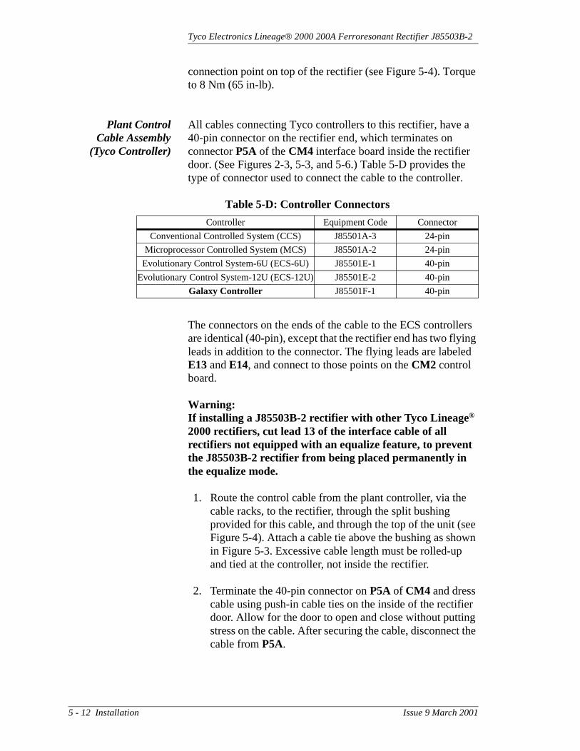
Tyco Electronics Lineage® 2000 200A Ferroresonant Rectifier J85503B-2
connection point on top of the rectifier (see Figure 5-4). Torque to 8 Nm (65 in-lb).
Plant ControlCable Assembly
(Tyco Controller)
All cables connecting Tyco controllers to this rectifier, have a 40-pin connector on the rectifier end, which terminates on connector P5A of the CM4 interface board inside the rectifier door. (See Figures 2-3, 5-3, and 5-6.) Table 5-D provides the type of connector used to connect the cable to the controller.
The connectors on the ends of the cable to the ECS controllers are identical (40-pin), except that the rectifier end has two flying leads in addition to the connector. The flying leads are labeled E13 and E14, and connect to those points on the CM2 control board.
Warning:If installing a J85503B-2 rectifier with other Tyco Lineage®
2000 rectifiers, cut lead 13 of the interface cable of all rectifiers not equipped with an equalize feature, to prevent the J85503B-2 rectifier from being placed permanently in the equalize mode.
1. Route the control cable from the plant controller, via the cable racks, to the rectifier, through the split bushing provided for this cable, and through the top of the unit (see Figure 5-4). Attach a cable tie above the bushing as shown in Figure 5-3. Excessive cable length must be rolled-up and tied at the controller, not inside the rectifier.
2. Terminate the 40-pin connector on P5A of CM4 and dress cable using push-in cable ties on the inside of the rectifier door. Allow for the door to open and close without putting stress on the cable. After securing the cable, disconnect the cable from P5A.
Table 5-D: Controller Connectors
Controller Equipment Code Connector
Conventional Controlled System (CCS) J85501A-3 24-pin
Microprocessor Controlled System (MCS) J85501A-2 24-pin
Evolutionary Control System-6U (ECS-6U) J85501E-1 40-pin
Evolutionary Control System-12U (ECS-12U) J85501E-2 40-pin
Galaxy Controller J85501F-1 40-pin
5 - 12 Installation Issue 9 March 2001

Tyco Electronics Lineage® 2000 200A Ferroresonant Rectifier J85503B-2
3. Determine the number to be assigned the rectifier in the rectifier lineup, that is, 1, 2, 3, etc.
4. If the controller is an MCS, cut lead TP0, TP1, TP2 (pins 19, 20, 21) in the controller end of the cable. (See the controller manual.) This signals to the controller that the rectifier is a J85503B-2. If the controller is a CCS, do not cut any lead.
5. Remove the plastic covers on the back of the bay housing CCS and MCS controllers. The backs of the controllers have sixteen 24-pin connectors labeled Rect 1 through Rect 16.
For ECS controllers, open the front panel and thread the control cable through the slot on the right side of the controller. On the backplane of the lower shelf inside the controller, the ECS-6U has six 40-pin connectors labeled Rect 1 through Rect 6. The ECS-12U has twelve 40-pin connectors labeled Rect 1 through Rect 12
Warning:Remove the REG fuse associated with the rectifier from the controller.
6. Plug the cable into the connector assigned to the rectifier number determined in Step (3) above. This action will cause a minor alarm in an MCS controller. Therefore, notify alarm personnel that the unit is being installed.
7. If the rectifier is connected to a Tyco controller, verify that the rectifier S2.1 switch on the 330C interface board, CM4, is in the disable position. An MCS controller must have version 4 software to enable an equalize feature. If the MCS has version 4 software, cut strap ST1 on circuit module CP2 in the controller. This allows the equalize feature to operate correctly without causing the rectifier to shut down. The ECS-6U controller automatically enables
Issue 9 March 2001 Installation 5 - 13

Tyco Electronics Lineage® 2000 200A Ferroresonant Rectifier J85503B-2
equalize, and the CCS controller does not have a provision for equalize.
8. Dress and tie down the cable to provide stress relief at the connector.
9. This step is not necessary if a Galaxy controller is used with the H285-226 L60 enhanced signals control cable. If -48 volt rectifiers are to be operated in load share, connect a 20 gauge wire from TB3-7 on CM4 to TB3-8 on CM4 of the adjacent rectifier. See Figure 5-6. The wire must be UL recognized with minimum ratings of 80° C and 150 volts ac. All load-sharing rectifiers must be “daisy-chain” connected in this manner.
Figure 5-6: CM4 Interface Board (330C)
Connector forPlant ControlCable
Connections forSpecialApplicationsLoad Share
VoltageAdjustmentPotentiometerfor SpecialApplicationsLoad Share(NLS)
5 - 14 Installation Issue 9 March 2001

Tyco Electronics Lineage® 2000 200A Ferroresonant Rectifier J85503B-2
In addition to the signals provided when a Tyco controller is used, 34 signals are readily accessible on the CM4 interface board via terminal strips TB1, TB2, and TB3. Note that when a Tyco controller is used, no connections are permitted from an external alarm/control bay to R+, R-, BAT and GND located on TB1 and TB2. When a Tyco controller and an external monitoring system are used with the rectifier, the user provides the control cable assembly which links the rectifier to the external monitoring system. All 34 signals obtained from TB1, TB2, and TB3 are also present in a Tyco controller, except the following:
RM48: This signal must be connected to turn the rectifier on or off remotely and should not be confused with the TR signal used to shut down the rectifier remotely.
RFA/CFA: This signal indicates that the rectifier’s RFA relay has operated or that ac power is lost or turned off. This is not the same as an RFA signal.
EQL/EQLR: Shorting these signals together places the rectifier in equalize mode. These signals can be used with non-Tyco controllers or other monitoring systems provided the level of the selective high voltage shutdown (HVSD) on the controller is raised.
E25 and E26 on CM1, the 329A fuse board, provide access to the 50mv, 250A shunt. E22-E23-E24 is an isolated RFA transfer contact.
10. Secure the control cable on the cable rack and disconnect terminal strips TB1, TB2, and TB3 from the CM4 interface board.
Plant ControlCable Assembly
(External Alarm/Control Bay)
If a non-Tyco controller is used, the external alarm/control bay cable assembly is provided by the user. It connects to terminal strips TB1, TB2, and TB3 of the CM4 interface board located in the rectifier. Thirty-four signals are accessible from the TB1, TB2, and TB3 terminal strips.
1. You may connect all the signals to the external alarm/control bay. However, you must connect the following signals:
Issue 9 March 2001 Installation 5 - 15

Tyco Electronics Lineage® 2000 200A Ferroresonant Rectifier J85503B-2
R+ and R- to regulate externally at the batteries BAT and GRD to energize the TR, HV, and EQ relays
The BAT signal typically is the battery voltage.
2. Route the control cable from the external monitoring system to the rectifier via the cable rack. See Figures 5-4 and 5-3 for the connection point and Table B of note 311 on SD-83281-01, which describes the function of each signal.
3. Connect and enable load share, if required, as above.
The rectifier is now installed. The last three sections in this chapter provide additional information and optional procedures that may be needed at installation. If not, proceed to Section 6, Testing.
DIP Switch Settings
This section describes the DIP switch settings on circuit modules in theJ85503B-2 rectifier. Figures 5-7 and 5-8 show the DIP switch label inside the rectifier door .Figures 6-2, 6-3, 7-1, and 5-6 show CM1, CM2, CM3, and CM4, respectively. If the settings on the rectifier do not meet the requirements of your plant, change them according to this section and label.
208F ControlBoard (CM2)
S1.1 through S1.5 and S1.8 ensure stable rectifier output voltage for various Tyco rectifiers. For the J85503B-2, the switches are factory set for operation with a battery. If the rectifier is operated without a battery, change the settings indicated in the options column of Figure 5-7.
S1.6 controls the time of the walk-in circuit and is factory set for a walk-in time of about 10 seconds. Changing the factory setting will eliminate the rectifier walk-in.
S1.9 enables load share. The factory setting is off (load share disabled). This feature is available only on 48 volt rectifiers.
S2.1 through S2.8 configure the rectifier as either a 24-volt or a 48-volt rectifier. For the J85503B-2, S2.1 through S2.8 are factory set and should not be changed.
5 - 16 Installation Issue 9 March 2001

Tyco Electronics Lineage® 2000 200A Ferroresonant Rectifier J85503B-2
Figure 5-7: 48V DIP Switch Label
*
FU
NC
TIO
NS
WIT
CH
BO
AR
DF
IELD
AD
JFA
CT
OR
YS
ET
TIN
GO
PT
ION
(SW
ITC
HS
ET
TIN
GS
)
DIP
SW
ITC
HS
ET
TIN
GS
CM
2
YE
S
S1.
1
1
STA
BIL
ITY
NE
TW
OR
K
S1.
8
YE
S1 1
STA
BIL
ITY
NE
TW
OR
K
YE
S
S1.
2Y
ES
0S
1.3
YE
S0
S1.
4N
O0
S1.
5N
O1
SE
ETA
BLE
B
S1.
6N
O0
S1.
70
RE
CT
SE
NS
E: S
ET
TO
1
S1.
90
S1.
10
NO
BU
HV
SD
(24/
48V
)
1
STA
BIL
ITY
NE
TW
OR
KS
TAB
ILIT
YN
ET
WO
RK
STA
BIL
ITY
NE
TW
OR
KW
ALK
-IN
CO
NT
RO
LB
AT
T/B
AT
TE
RY
LES
SS
TAB
ILIT
YN
ET
WO
RK
LOA
DS
HA
RE
STA
BIL
ITY
NE
TW
OR
K
S2.
51
NO
RE
CT
SE
NS
E(4
8V)
S2.
1
S2.
4
RE
CT
SE
NS
E(4
8V)
NO
01
NO
RE
CT
SE
NS
E(2
4V)
S2.
2R
EC
T S
EN
SE
(24V
)N
O0
S2.
3
RE
CT
SE
NS
E: S
ET
TO
1
0S
2.6
ISH
VS
D(2
4/48
V)
NO
0S
2.7
FU
SE
(24/
48V
)N
O0
S2.
8FA
CT
OR
YT
ES
TN
O0
S2.
9R
EM
OT
ES
EN
SE
YE
S0
S2.
10R
EM
OT
ES
EN
SE
YE
S0
S3.
1
S3.
400
S3.
20
S3.
30
S3.
5IS
HV
SD
(48V
)Y
ES
1S
3.6
ISH
VS
D(2
4V)
NO
0S
3.7
ISH
VS
DA
DJ
YE
SS
3.8
ISH
VS
DA
DJ
YE
S
S3.
501
S3.
9
NO
STA
BIL
ITY
NE
TW
OR
K
125
AR
EC
T
0S
3.10
NO
TU
SE
DX
S3.
1
S3.
4
400
AR
EC
TN
O
00
NO
100
AR
EC
TS
3.2
*
200
AR
EC
TN
O1
S3.
3
SE
ETA
BLE
B
NL/
FL
SE
TT
ING
(24/
48V
)N
O1
S3.
6N
L/F
LS
ET
TIN
G(2
4/48
V)
NO
1
S1.
1
NO
NO
EN
DC
ELL
NO
HV
SD
(24V
)
1
S2.
31
S1.
2N
OE
ND
CE
LLN
O1
S1.
3B
UH
VS
D(2
4V)
NO
0S
1.4
BU
HV
SD
(48V
)N
O1
S2.
1Y
ES
LOC
AL
EQ
UA
LIZ
EY
ES
ME
TE
RO
N/W
ITH
UN
ITO
FF
0S
2.2
0S
2.4
HV
SD
(48V
)N
O1
S2.
5T
R(2
4V)
NO
0S
2.6
TR
(48V
)N
O1
BA
TT
ER
YLE
SS
: SE
T T
O0
EN
AB
LE: S
ET
TO
10=
ME
TE
RO
FF
/ WIT
HU
NIT
OF
F
CM
2
CM
2
CM
3
CM
1
CM
4
SE
ETA
BLE
A
SE
ETA
BLE
AS
EE
TAB
LEA
S3.
3
YE
SY
ES
YE
SY
ES
BU
HV
SD
LEV
EL
AD
JB
UH
VS
DLE
VE
LA
DJ
YE
SY
ES
BA
TT
ER
YLE
SS
: SE
TT
O1
0
SE
ETA
BLE
A
SE
T T
O1
TO
EN
AB
LELO
AD
SH
AR
E
BU
HV
SD
LEV
EL
AD
JB
UH
VS
DLE
VE
LA
DJ
S3.
4
BA
TT
ER
YLE
SS
: SE
T T
O1
YE
S
S2.
7S
PE
CIA
LA
PP
LIC
ATIO
NLO
AD
SH
AR
EY
ES
0S
2.8
NO
TU
SE
DX
S2.
9N
OT
US
ED
XS
2.10
NO
TU
SE
DX
SE
T T
O1
TO
EN
AB
LE
SE
T T
O1
FO
RC
UR
RE
NT
LIM
IT50
%
BU
HV
SD
S3.
1S
3.2
SIZ
ET
OR
QU
EIN
.-LB
.C
ON
NE
CT
ION
IDE
NT
IFIC
AT
ION
LIS
TC
ON
FIG
UR
AT
ION
TO
RQ
UE
RE
QU
IRE
ME
NT
S
WH
EN
INS
TALL
ING
TH
ISR
EC
TIF
IER
WIT
HO
TH
ER
AT
&T
LIN
EA
GE
RE
CT
IFIE
RS
, LE
AD
13O
FT
HE
CO
NT
RO
LLE
RT
O R
EC
TIF
IER
INT
ER
FAC
EC
AB
LEO
FA
LLR
EC
TIF
IER
SN
OT
EQ
UIP
PE
DW
ITH
AN
EQ
UA
LIZ
EF
EA
TU
RE
MU
ST
BE
CU
TT
OP
RE
VE
NT
TH
ISR
EC
TIF
IER
FR
OM
BE
ING
PLA
CE
DP
ER
MA
NE
NT
LYIN
TH
EE
QU
ALI
ZE
MO
DE
OF
OP
ER
AT
ION
.
WA
RN
ING
OU
TP
UT
DC
3/8
-16
ALL
240
C.O
. GR
OU
ND
1/4
-20
ALL
65
RE
PLA
CE
ME
NT
FU
SE
F1,
F2,
AN
DF
3F
OR
TH
EC
IRC
UIT
MO
DU
LEC
M1
AR
ER
AT
ED
FO
R1/
2AA
ND
60V
DC
.W
P-9
0247
,L3
CO
MC
OD
E40
5673
161
SP
AR
EF
US
E
A.C
.E.G
.A
LL10
-32
30
NO
TE
: SE
EP
RO
DU
CT
MA
NU
AL
FO
RD
ETA
ILE
DE
XP
LAN
AT
ION
OF
SW
ITC
HS
ET
TIN
GS
.
1
XX
XX
XX
XX
X_X
01
BU
HV
SD
-B
AC
KU
PH
IGH
VO
LTA
GE
SH
UT
DO
WN
ISH
VS
D-
INT
ER
NA
LS
ELE
CT
IVE
HIG
HV
OLT
AG
ES
HU
TD
OW
N
SP
AR
EF
US
E
RE
PLA
CE
ME
NT
FU
SE
F1
FO
RT
HE
CIR
CU
ITM
OD
ULE
CM
2IS
RA
TE
DF
OR
.18A
AN
D60
VD
C.
WP
-902
47,
L1C
OM
CO
DE
4053
7300
2
SE
T T
O 0
IF R
EC
TIF
IER
OU
TP
UT
VO
LTA
GE
ISS
ET
AB
OV
ES
3.7
&S
3.8
SE
TT
ING
S**W
AR
NIN
G: A
DJU
ST
ME
NT
OF
NO
N-F
IELD
AD
JUS
TAB
LES
WIT
CH
SE
TT
ING
SM
AY
RE
SU
LT IN
DA
MA
GE
TO
TH
ER
EC
TIF
IER
.30 4
TO
RQ
UE
Nm 8
0
0100
BU
HV
SD
S3.
1
0
S3.
2S
3.3
1
S3.
4
100
TAB
LEA
ISH
VS
D
0
S3.
7S
3.8
0
CLO
SE
D
TAB
LEB
570 1 0 0
00 1 0 0 0
11 1 1
1
550 1 0
01 0 1
10 0 1
156
0
OP
EN
0
58
65.5
SE
T T
O 1
WH
EN
CU
RR
EN
T L
IMIT
ISA
DJU
ST
ED
TO
LE
SS
TH
AN
50%
OF
FU
LLLO
AD
RA
TIN
G
66.5
67.5
0
ON
OF
F
64.5
63.5
62.5
61.5
60.5
59.5
BA
TT
ER
YLE
SS
: SE
T T
O0
Issue 9 March 2001 Installation 5 - 17
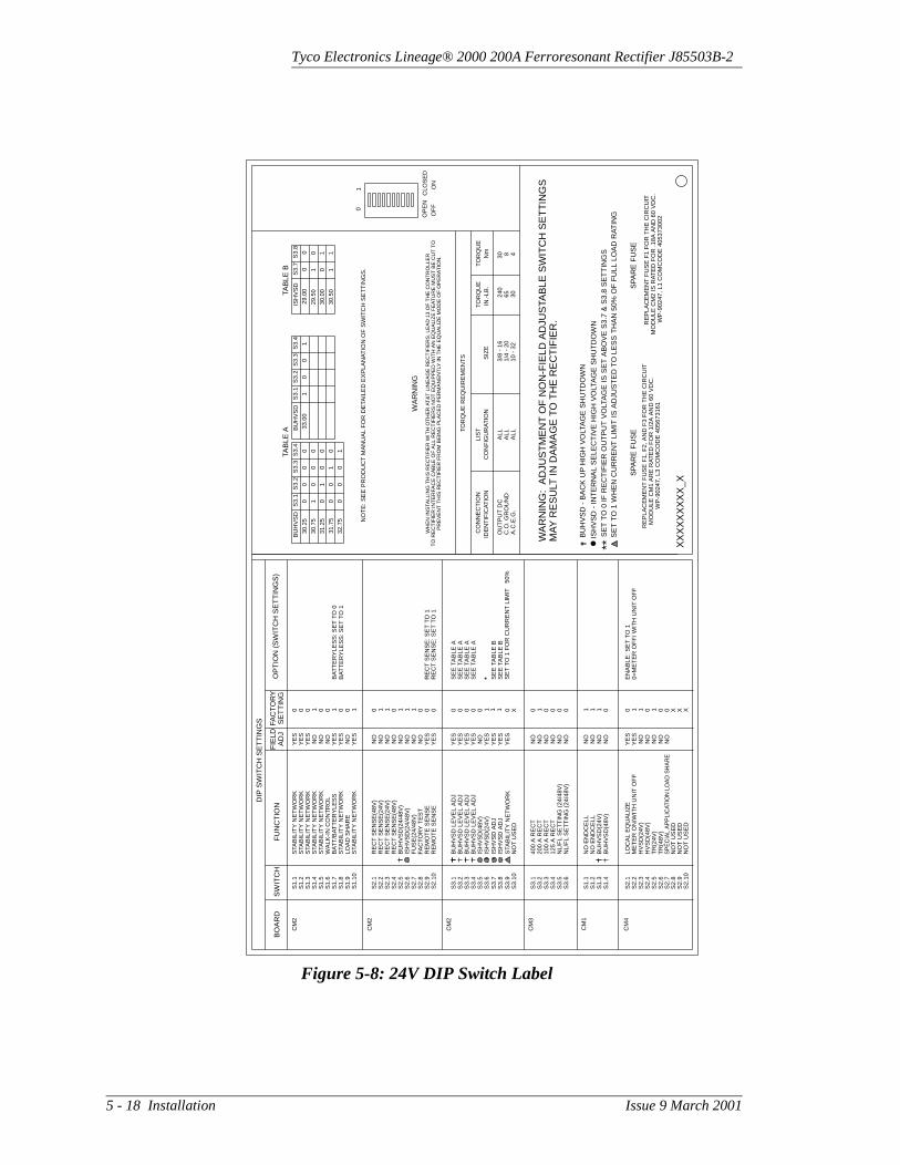
Tyco Electronics Lineage® 2000 200A Ferroresonant Rectifier J85503B-2
Figure 5-8: 24V DIP Switch Label
*
FU
NC
TIO
NS
WIT
CH
BO
AR
DF
IELD
AD
JFA
CT
OR
YS
ET
TIN
GO
PT
ION
(SW
ITC
HS
ET
TIN
GS
)
DIP
SW
ITC
HS
ET
TIN
GS
CM
2
YE
S
S1.
1
1
STA
BIL
ITY
NE
TW
OR
K
S1.
8
YE
S0 1
STA
BIL
ITY
NE
TW
OR
K
YE
S
S1.
2Y
ES
0S
1.3
YE
S0
S1.
4N
O1
S1.
5N
O0
SE
ETA
BLE
B
S1.
6N
O0
S1.
70
RE
CT
SE
NS
E: S
ET
TO
1
S1.
90
S1.
10
NO
BU
HV
SD
(24/
48V
)
1
STA
BIL
ITY
NE
TW
OR
KS
TAB
ILIT
YN
ET
WO
RK
STA
BIL
ITY
NE
TW
OR
KW
ALK
-IN
CO
NT
RO
LB
AT
T/B
AT
TE
RY
LES
SS
TAB
ILIT
YN
ET
WO
RK
LOA
DS
HA
RE
STA
BIL
ITY
NE
TW
OR
K
S2.
50
NO
RE
CT
SE
NS
E(4
8V)
S2.
1
S2.
4
RE
CT
SE
NS
E(4
8V)
NO
10
NO
RE
CT
SE
NS
E(2
4V)
S2.
2R
EC
T S
EN
SE
(24V
)N
O1
S2.
3
RE
CT
SE
NS
E: S
ET
TO
1
1S
2.6
ISH
VS
D(2
4/48
V)
NO
1S
2.7
FU
SE
(24/
48V
)N
O1
S2.
8FA
CT
OR
YT
ES
TN
O0
S2.
9R
EM
OT
ES
EN
SE
YE
S0
S2.
10R
EM
OT
ES
EN
SE
YE
S0
S3.
1
S3.
400
S3.
20
S3.
30
S3.
5IS
HV
SD
(48V
)N
O0
S3.
6IS
HV
SD
(24V
)Y
ES
1S
3.7
ISH
VS
DA
DJ
YE
SS
3.8
ISH
VS
DA
DJ
YE
S
S3.
501
S3.
9
NO
STA
BIL
ITY
NE
TW
OR
K
125
AR
EC
T
0S
3.10
NO
TU
SE
DX
S3.
1
S3.
4
400
AR
EC
TN
O
00
NO
100
AR
EC
TS
3.2
*
200
AR
EC
TN
O1
S3.
3
SE
ETA
BLE
B
NL/
FL
SE
TT
ING
(24/
48V
)N
O0
S3.
6N
L/F
LS
ET
TIN
G(2
4/48
V)
NO
0
S1.
1
NO
NO
EN
DC
ELL
NO
HV
SD
(24V
)
1
S2.
31
S1.
2N
OE
ND
CE
LLN
O1
S1.
3B
UH
VS
D(2
4V)
NO
1S
1.4
BU
HV
SD
(48V
)N
O0
S2.
1Y
ES
LOC
AL
EQ
UA
LIZ
EY
ES
ME
TE
RO
N/W
ITH
UN
IT O
FF
0S
2.2
1S
2.4
HV
SD
(48V
)N
O0
S2.
5T
R(2
4V)
NO
1S
2.6
TR
(48V
)N
O0
BA
TT
ER
YLE
SS
: SE
TT
O0
EN
AB
LE: S
ET
TO
10=
ME
TE
RO
FF
/ WIT
H U
NIT
OF
F
CM
2
CM
2
CM
3
CM
1
CM
4
SE
ETA
BLE
A
SE
ETA
BLE
AS
EE
TAB
LEA
S3.
3
YE
SY
ES
YE
SY
ES
BU
HV
SD
LEV
EL
AD
JB
UH
VS
DLE
VE
LA
DJ
YE
SN
OB
AT
TE
RY
LES
S: S
ET
TO
1
0
SE
ETA
BLE
AB
UH
VS
DLE
VE
LA
DJ
BU
HV
SD
LEV
EL
AD
J
S3.
4
YE
S
S2.
7S
PE
CIA
LA
PP
LIC
ATIO
NLO
AD
SH
AR
EN
O0
S2.
8N
OT
US
ED
XS
2.9
NO
TU
SE
DX
S2.
10N
OT
US
ED
X
SE
TT
O1
FO
RC
UR
RE
NT
LIM
IT50
%
BU
HV
SD
S3.
1S
3.2
SIZ
ET
OR
QU
EIN
.-LB
.C
ON
NE
CT
ION
IDE
NT
IFIC
AT
ION
LIS
TC
ON
FIG
UR
AT
ION
TO
RQ
UE
RE
QU
IRE
ME
NT
S
WH
EN
INS
TALL
ING
TH
ISR
EC
TIF
IER
WIT
HO
TH
ER
AT
&T
LIN
EA
GE
RE
CT
IFIE
RS
, LE
AD
13O
FT
HE
CO
NT
RO
LLE
RT
O R
EC
TIF
IER
INT
ER
FAC
EC
AB
LEO
FA
LLR
EC
TIF
IER
SN
OT
EQ
UIP
PE
DW
ITH
AN
EQ
UA
LIZ
EF
EA
TU
RE
MU
ST
BE
CU
TT
OP
RE
VE
NT
TH
ISR
EC
TIF
IER
FR
OM
BE
ING
PLA
CE
DP
ER
MA
NE
NT
LYIN
TH
EE
QU
ALI
ZE
MO
DE
OF
OP
ER
AT
ION
.
WA
RN
ING
OU
TP
UT
DC
3/8
-16
ALL
240
C.O
. GR
OU
ND
1/4
-20
ALL
65
RE
PLA
CE
ME
NT
FU
SE
F1,
F2,
AN
DF
3F
OR
TH
EC
IRC
UIT
MO
DU
LEC
M1
AR
ER
AT
ED
FO
R1/
2AA
ND
60V
DC
.W
P-9
0247
, L3
CO
MC
OD
E40
5673
161
SP
AR
EF
US
E
A.C
.E.G
.A
LL10
-32
30
NO
TE
: SE
EP
RO
DU
CT
MA
NU
AL
FO
RD
ETA
ILE
DE
XP
LAN
AT
ION
OF
SW
ITC
HS
ET
TIN
GS
.1
XX
XX
XX
XX
X_X
01
BU
HV
SD
-B
AC
KU
PH
IGH
VO
LTA
GE
SH
UT
DO
WN
ISH
VS
D-
INT
ER
NA
LS
ELE
CT
IVE
HIG
HV
OLT
AG
ES
HU
TD
OW
N
SP
AR
EF
US
E
RE
PLA
CE
ME
NT
FU
SE
F1
FO
RT
HE
CIR
CU
ITM
OD
ULE
CM
2IS
RA
TE
DF
OR
.18A
AN
D60
VD
C.
WP
-902
47, L
1C
OM
CO
DE
4053
7300
2
SE
TT
O0
IFR
EC
TIF
IER
OU
TP
UT
VO
LTA
GE
ISS
ET
AB
OV
ES
3.7
&S
3.8
SE
TT
ING
S**
WA
RN
ING
:A
DJU
ST
ME
NT
OF
NO
N-F
IELD
AD
JUS
TAB
LES
WIT
CH
SE
TT
ING
SM
AY
RE
SU
LT IN
DA
MA
GE
TO
TH
ER
EC
TIF
IER
.
30 4
TO
RQ
UE
Nm 8
0
0100
BU
HV
SD
S3.
1
0
S3.
2S
3.3
1
S3.
4
100
TAB
LEA
ISH
VS
D
0
S3.
7S
3.8
0
CLO
SE
D
TAB
LEB
30.0
0
0 1 0 0
00 1 0 0 0
1
1
29.0
0
01
129
.50
0
OP
EN
0
30.5
0
SE
TT
O1
WH
EN
CU
RR
EN
TLI
MIT
ISA
DJU
ST
ED
TO
LES
ST
HA
N50
%O
FF
ULL
LOA
DR
AT
ING
0
ON
OF
F
33.0
0
32.7
5
31.7
5
31.2
5
30.7
5
30.2
5
5 - 18 Installation Issue 9 March 2001

Tyco Electronics Lineage® 2000 200A Ferroresonant Rectifier J85503B-2
S2.9 and S2.10 provide local or remote sense. In the factory setting position, the rectifier senses the output voltages remotely via the regulation leads. If the settings are changed, the voltage is regulated at the output terminals of the rectifier.
S3.1 through S3.4 adjust the level of the backup high voltage shutdown (BUHVSD). See Table A of Figure 5-8 for the range of BUHVSD settings. The factory setting is 59.5 Vdc for 48 volt rectifiers or 30.25 Vdc for 24 volt rectifiers.
S3.5 and S3.6 are factory settings that notify the control circuit that the rectifier is configured as a 48 or 24 volt rectifier.
S3.7 and S3.8 permit the internal selective high-voltage shutdown (ISHVSD) level to be adjusted to 55, 56, 57 or 58 volts. The factory setting is 58 volts.
S3.9 is used to maintain voltage stability when the current limit is set below 50% of full load.
S3.10 is not used.
323D DigitalMeter Board
(CM3)
S3.1 through S3.4 tell the rectifier’s ammeters the rectifier's current capacity.
S3.5 through S3.6 configure the NL/FL switch on the front of the rectifier for either 24 or 48 volts.
329A Fuse Board(CM1)
S1.1 through S1.4 are not field adjustable.
330C InterfaceBoard (CM4)
S2.1 enables the front panel equalize switch on the rectifier.
S2.2 keeps the front panel display on or off when the control switch is in the off position. When S2.2 is on, the front panel display is always on. When S2.2 is off, the front panel display is off when the rectifier is turned off either via the front panel or via the controller.
S2.3-S2.6 configure the rectifier for operation with a 24- or 48-volt plant.
Issue 9 March 2001 Installation 5 - 19

Tyco Electronics Lineage® 2000 200A Ferroresonant Rectifier J85503B-2
Converting AC Voltage
The main list number of the J85503B-2 rectifier (Lists 1, 2, 3, 4, 5, or 6) determines the ac input voltage of the unit. (See Table 3-A.) Lists 1 and 2 have 208-volt ac input and use the 425C transformer board. Lists 3 and 4 have 240-volt ac input and use the 425D transformer board. Lists 5 and 6 have 480-volt ac input and use the 425F transformer board. Each list number requires different connections to windings of main transformers T1 and T2.
Underwriters Laboratory, Inc. (UL) requires the proper circuit module, wiring configuration, input, and product identifying labels for any unit. Therefore, only Tyco installation personnel are permitted to implement ac input conversions.
Initial Battery Charging
Initial battery charging should be planned as part of the plant installation.
NoteIf initial battery charging is desired, the rectifier should be tested before following this procedure. (See Section 6.)
The J85503B-2 rectifier is capable of supplying a new battery string with its initial charge. Since the voltage levels recommended by battery manufacturers for initial battery charging are considerably above the normal plant voltage, neither the battery nor the rectifier used to supply its initial charge should be connected to the rest of the plant during this procedure. One rectifier is sufficient to supply the charge.
1. Set the ac supply and rectifier controls as shown in Table 5-E
Table 5-E: Control Settings for Initial Battery Charge
Controls Position/Status
Rectifier Power Switch Off (down)
Rectifier Circuit Breaker (CB1) Off (down)
Float Adj potentiometerFully counterclockwise (20 turns to click)
Plant control connectors P5A, TB1, and TB2 on CM4 interface board
Disconnected from CM4
Associated REG fuse in plant controller Removed
5 - 20 Installation Issue 9 March 2001

Tyco Electronics Lineage® 2000 200A Ferroresonant Rectifier J85503B-2
2. To disable internal selective high voltage shutdown (ISHVSD), open S3.5 on the CM2 board for 48V rectifiers. For 24V applications, open S3.6 to disable ISHVSD. See Figure 6-3.
3. To raise the backup HVSD level, adjust S3.1-S3.4 on CM2 to one of the levels given in Table A on the rectifier door. Choose a level 1 to 2 volts above the initial charge voltage.
4. Close the rectifier door and turn the Power switch On. The green Power LED must be on. (If not, do not attempt to turn on the circuit breaker, CB1. Troubleshoot the problem per Section 7). Keep the rectifier on for 10 seconds.
5. Hold the meter selector switch in the Rect V position, and use a small screwdriver to turn the Float Adj potentiometer clockwise until the digital meter reads approximately battery voltage, typically 52 volts.
6. Turn circuit breaker CB1 on (up).
7. Adjust the Float Adj potentiometer to obtain the desired initial charge voltage within the limits specified by the battery manufacturer.
After completing the initial charge,
1. Turn the rectifier Power switch Off and the circuit breaker off (down).
2. Restore the original switch settings by closing S3.5 (48V) or S3.6 (24V) and restoring the backup HVSD on the CM2 board. Refer to switch setting label located on the inside of the rectifier door.
3. To restore the rectifier to service, follow the procedure in Section 7.
Issue 9 March 2001 Installation 5 - 21


Tyco Electronics Lineage® 2000 200A Ferroresonant Rectifier J85503B-2
6 Testing
General This section gives test procedures for newly installed and/or operating rectifiers. If the plant in which a rectifier is being installed has never been operational, the plant and controller tests must be performed before the rectifier tests. Consult the plant and controller product manuals for their installation test procedures.
Rectifiers can be tested on- or off-line. “On-line” means a battery string and/or office load is connected to the rectifier. A dummy test load is required for testing off-line, and a Battery Plant Simulator Test Set is desirable.Without a simulator, a minimum set of tests can be performed. See page 6-2 for a description of the simulator and test load. For troubleshooting and diagnostic procedures, refer to Section 7. Those unfamiliar with the function of rectifier controls and indicators should read Section 2.
Precautions When working on power systems, observe safety precautions in Section 4 and those within each procedure.
• The ac input voltage powers certain control circuits and relays, the front panel LEDs except ac fail, and the ac contactor. Voltage is available to these circuits whenever the ac service is available to the rectifier.
• Remote sensing of rectifier output occurs via the plant control cable connected to P5A or TB1 and TB2 on CM4. This cable must be disconnected when internal sensing is desired, as when testing off line using a test load.
Issue 9 March 2001 Testing 6 - 1

Tyco Electronics Lineage® 2000 200A Ferroresonant Rectifier J85503B-2
Tools and Test Equipment
The following items for testing the rectifier.
• DMM (Digital Multimeter) Fluke 8060A or equivalent meter having 0.02 percent accuracy on dc scale
• Battery Plant Simulator Test Set (customer constructed, or equivalent)
• Test load, 52-volt or 24-volt with adjustment to provide a load of 480 amperes, 120 percent of the rectifier's rating
• Small screwdriver for adjusting potentiometers• Paper clip with insulation on one end or equivalent that can
be used to make an electrical connection between the power and alarm contact of a fuse.
Battery Plant Simulator Test Set
The Battery Plant Simulator Test Set is a convenient tool used to isolate communication trouble between the plant controller and the rectifier. It simulates the plant controller relative to receiving signals from, and sending signals to, the rectifier. If there is a problem and the rectifier works properly with the test set, the problem is either at the controller or in the interface wiring (plant cable).
Figure 6-1 shows how to construct a test set. (Note: The Battery Plant Simulator Test Set shown in Figure 6-1 is equivalent to a Tyco Electronics ITE6369 test set, which is not available to customers.)
Table 6-A shows how to connect the test set to the rectifier.
Warning
Do not turn the CB1 circuit breaker ON, close an external charge circuit breaker, or install an external charge fuse until told to do so.
Table 6-A: Test Set Connections
Test Clip Connection Figure Voltage
RedE13 on CM2(Positive side of capacitor C4)
6-3 +27V
BlackE14 on CM2(Negative side of capacitor C4)
6-3 GRD
Blue Cathode of diode CR56 on CM2 6-3 -V
White E25 on CM1 6-2 +V
6 - 2 Testing Issue 9 March 2001

Tyco Electronics Lineage® 2000 200A Ferroresonant Rectifier J85503B-2
Test Load Connection
Use the following procedures to connect a test load when called for in a test or other procedure. Test load connections are made on the internal bus of the rectifier. Therefore, to isolate the rectifier from the batteries and plant bus, the rectifier DC Output circuit breaker must be left open (off) while the test load is connected.
1. At the ac service panel, remove ac power to the rectifier.
2. Turn off (down) the rectifier CB1 circuit breaker.
WarningSupport the CM4 interface board with your hands when disconnecting the cable leads or damage to the interface board may result.Do NOT disconnect plant control cable connector J5A from interface board CM4 by pulling the cable.
3. Disconnect J5A from CM4 by unlatching first, then pulling the cable connector.
4. Refer to Figure 5-3 and connect the test load between the input bus to circuit breaker CB1, (labeled Test Load), and
Issue 9 March 2001 Testing 6 - 3

Tyco Electronics Lineage® 2000 200A Ferroresonant Rectifier J85503B-2
any convenient point on the ground bus anywhere in the plant.
Figure 6-1: Battery Plant Simulator Test Set
+27V Red Test Clip
PIN 5
P 25IN
PIN 16
PIN 4
PIN 6
PIN 39
P 38IN
P 34IN
P 37IN
P 31IN
P 27IN
P 2IN
Blue Test Clip
White Test Clip
Black Test Clip
PIN 12
BAT
R2
R12150
21501 WATT
21501 WATT
21501 WATT
21501 WATT
R3
R4
R5
MAN
1
1
1
1
1
2
2
2
2
2 3
3
3
1
1
1
2
2
2
F1
F2 1 1/3
1 1/3
TR
PWR
HV
RS
RFA
TRH
PH
MAN
RFA
TRH
PH or LOA
DPG
TR48
HV48
RS
RSR
APG
R+
R–
V–
V+
+27VReturn
Use 24 AWG multiconductor wire and 40-pin female connector fromAMP, Inc., Harrisburg PA. Cable will then plug into the P5A connectoron the CM4 board. The suggested AMP hardware part numbers areas follows:
To CM4Connector
P5A
Description
Housing
Cover
Cover
Quantity
1
1
1
Part Number
102398-8
102537-8
102536-8
Terminate the remaining 4 extension wires outside the brace with miniaturealligator clips, color-coded as shown.
6 - 4 Testing Issue 9 March 2001

Tyco Electronics Lineage® 2000 200A Ferroresonant Rectifier J85503B-2
Initial Conditions for Testing Off Line
The following steps verify that the rectifier responds properly to plant controller commands and outputs proper signals in return. Referring to Schematic Drawing SD83281-01 may be helpful while performing these procedures.
1. Verify that the ac supply and rectifier controls are as shown in Table 6-B.
2. Use the documentation for the particular battery plant to perform all the preliminary checks on the plant prior to the rectifier tests. If the rectifier is in a microprocessor- controlled plant with an efficiency algorithm feature, disable this feature. (See the appropriate controller manual for instructions.)
3. Using the digital multimeter (DMM) on the dc volts scale, make the following checks:
• Verify that dc voltage is not present between the rectifier output bus bars. See Figure 5-3.
• Install the regulation (REG) fuse associated with the rectifier in the plant controller.
• Check for battery voltage between pins 27 and 2 of control cable connector J5A. The J5A connector is at the rectifier end of the plant control cable. Pin 27 should be positive with respect to pin 2.
• As an extra precaution, check for battery voltage between ground and pin 2 (-48V or -24V rectifier) or pin 27 (+24V rectifier). If no voltage exists, there is a wiring problem associated with the control cable or controller. The problem must be found and repaired before proceeding with testing.
Table 6-B: Rectifier Control Settings for Testing Off Line
Controls Position/Status
Associated ac circuit breaker or fuses at the ac service distribution panel
Off or fuses removed and holders tagged “Out of service”
Rectifier Power switch Off (down)
Rectifier CB1 circuit breaker Off (down)
Float Add potentiometerFully counterclockwise (20 turns to click)
Plant control connector J5A (and J12, if applicable) on control cable
Disconnected from P5A (and P12) on CM4
Dip switch S1 settings on CM2 (See Figure 6-3.)
Off Battery switch settings as shown on door label (See Figure 5-7 or 5-8.)
Issue 9 March 2001 Testing 6 - 5

Tyco Electronics Lineage® 2000 200A Ferroresonant Rectifier J85503B-2
• With the BAT fuse installed in the plant controller, check for battery voltage between pin 5 of J5A and ground.
• If the plant is equipped with an MCS Controller or with a Galaxy Controller with Intelligent features, again on J5A, check for 15-20 volts dc between pins 35 and 31. Pin 35 should be positive with respect to pin 31.
4. Place the Battery Plant Simulator Test Set (Figure 6-1), at a convenient location near the rectifier. Connect J5A, on the other end of the cable from the test set, to connector P5A on the CM4 interface board mounted on the inside of the rectifier door. Connect the red, black, blue, and white test clips from the test set as detailed in Table 6-A. Refer to Figures 6-2 and 6-3.
Figure 6-2: CM1 Fuse Board with Clip Connections (Older version of CM1 on the left)
WhiteTestClip
WhiteTestClip
6 - 6 Testing Issue 9 March 2001

Tyco Electronics Lineage® 2000 200A Ferroresonant Rectifier J85503B-2
M
Figure 6-3: CM2 Board with Clip Connections
Isolated CurrentMeasuringAdjustmentPotentiometer
BlueTest Clip
RedTest Clip
BlackTest Clip
Current LimitPotentiometer
DIP Switch S1
Issue 9 March 2001 Testing 6 - 7

Tyco Electronics Lineage® 2000 200A Ferroresonant Rectifier J85503B-2
Testing Off Line The following tests involve use of the test load and a Battery Plant Simulator Test Set. Refer to page 6-2 for the procedure to connect a test load and pages 6-2 and 6-3 for a Battery Plant Simulator Test Set.
If the rectifier fails any of the tests in this section, replace the CM2 board and begin testing again.
Startup 1. Turn on the ac supply to the rectifier. The PWR lamp on the test set should light brightly. If it does not light properly, check the connection of the two small red and black clip leads. They may be reversed or otherwise incorrectly connected. These leads provide the operating voltages in the test set, and the red lead should be approximately +27 volts dc with respect to the black lead.
2. The PWR lamp should remain lit during the remaining tests as long as the ac supply is turned on.
3. Set the test meter to the 100 volts range, and connect it to the Rect jacks on the rectifier control panel. (See Figure 2-2.)
4. Adjust the test load so that when the rectifier is turned on, it will deliver 10-40A, 5 to 20 percent of full load.
5. Place the S1 switch on CM4 in the LOC position (see Figure 5-5), and turn the Power switch On. The rectifier should start and the green Power LED on the front panel should light. The test meter should indicate 40-50 or 22-26 volts. The MAN lamp on the test set should light and remain lit as long as the rectifier is turned on.
Regulation(NL/FL) Test
1. Watch the test meter and move the Rect Test switch to NL. In the NL position, the voltage should drop between 0.3 and 0.6 volt.
2. Repeat Step 1 with the Rect Test switch in the FL position. The voltage should increase between 0.1 and 0.4 volt.
Rectifier FailureAlarm Test
1. Holding the insulation on a piece of bare wire or the end of a paper clip, insert the wire into the fuse holder of the F1 alarm fuse on CM1. Note that the rectifier shuts down, and
6 - 8 Testing Issue 9 March 2001

Tyco Electronics Lineage® 2000 200A Ferroresonant Rectifier J85503B-2
the RFA and FA LEDs on the control panel and RFA lamp on the test set light.
2. Turn the Power switch Off, then back On. The rectifier should start, and the LEDs lights should go off.
3. Repeat Steps (1) and (2) at the F2 and F3 fuses on CM1.
Current LimitTest
NotesAdjust the current limit only after verifying that a current limit problem exists. It is recommended that this test be performed on battery.
Vout is the voltage reading between the rectifier output bus bars. See Figure 5-3.
1. Connect the test meter to the Test Load bus bar at the bottom of CB1 and the +V output bus bar.
2. Strap a short across E18 to E33 on CM2, see Figure 6-3.
3. At Iload = 200-202A, 100 to 101 percent of rated output current, use the Float Adj potentiometer to adjust Vout to 52.08 (26.04) volts.
4. Remove strap from E18 to E33. Observe that Vout is 51.98 (25.99) to 52.03 (26.0) volts. If not, see Section 7.
5. Increase the load, as indicated on the load box to 218-222 amperes, 110± 1 percent. Vout should be below 51.58 (25.9) volts. If not, see Section 7.
6. Decrease the load to 192-196A, 96 to 98 percent of the rectifier rating. Observe that Vout is greater than 52.03 (26.01) volts.
Phase FailureAlarm (PHA) Test
1. Set the load to 100-120A, 50 to 60 percent of the rectifier's rated amperage.
2. With the Power switch still On, turn off the ac service and note that the rectifier shuts down and that both the PWR and MAN lamps on the test set go off.
Issue 9 March 2001 Testing 6 - 9

Tyco Electronics Lineage® 2000 200A Ferroresonant Rectifier J85503B-2
3. Verify that no ac voltage is present on the input leads of the ac contactor K1. (See Figure 5-3.)
4. Disconnect one input lead, L1, L2, or L3 on K1, or at the ac service panel, whichever is more convenient. Insulate the lead.
5. Turn on the ac at the service panel. The rectifier should not restart, and the PWR, MAN, and PH lamps on the test set should light. The PHA lamp on the rectifier should light.
6. Turn off the ac at the service panel and reconnect the input lead.
7. Turn on the ac at the service panel. The rectifier should restart. On the test set, only the PWR and MAN lamps should light.
8. Repeat for the other two phases.
Backup HighVoltage Shutdown
(HVSD) Test
1. Disable the internal selective HVSD by opening S3.5 or S3.6 on CM2. Move switch to the left. See Figure 6-3.
2. Slowly turn the Float Adj potentiometer clockwise until the rectifier shuts down.
3. When the rectifier shuts down its voltage should correspond to the settings of S3.1 through S3.4 of the CM2 control board. The factory setting is 59.5± 0.5 volts for 48V rectifiers. The factory setting for 24V applications is 30.25 ± 0.25 volts. The RFA LEDs on the rectifier and the test set should light.
4. Turn the Float Adj potentiometer counterclockwise four full turns.
5. Restart the rectifier using the RS switch on the test set.
6. Adjust the voltage to approximately 52.0 (26.0) volts. The RFA lamps on the rectifier and the test set should go out.
7. To enable ISHVSD, close S3.5 on CM2.
6 - 10 Testing Issue 9 March 2001

Tyco Electronics Lineage® 2000 200A Ferroresonant Rectifier J85503B-2
Control (TR) Test 1. Press and hold the transfer rectifier (TR) switch on the test set for 5 seconds. The rectifier should turn off simulating a remote shutdown from the controller. The TRH lamp on the test set should light.
2. Release the switch. The rectifier should restart and the TRH lamp should go out.
3. Reduce the test load to 0 amperes.
4. Press the HV switch on the test set. The rectifier should continue to operate.
Selective HighVoltage Shutdown
(SHVSD) andRestart
1. Adjust the test load so that the rectifier delivers 20 to 30A, 10 to 15 percent of its rated amperage.
2. Momentarily press the HV switch on the test set. The rectifier should shut down, and the RFA LEDs on the control panel and on the test set should light.
3. Momentarily press the RS switch on the test set. The rectifier should restart and both RFA lamps should go off.
Float/EqualizeTest
1. Adjust the load so that the rectifier delivers between 20 and 30 amperes.
2. Turn the Power switch Off.
3. Short TB2 terminals EQL and EQLR on CM4.
4. Turn the Power switch On. The equalize LED should light.
5. Use the Equal Adj potentiometer on the control panel to set the voltage per the plant requirement, normally 2.0 (1.0) volts above float voltage.
6. Turn the Power switch Off.
7. Remove strap from TB2 on CM4 or return it to original setting.
8. Turn the Power switch On.
Issue 9 March 2001 Testing 6 - 11

Tyco Electronics Lineage® 2000 200A Ferroresonant Rectifier J85503B-2
Local EqualizeControl Test
1. Set switch S2.1 on CM4 to on (right).
2. Move the FLT/EQ switch on the control panel (S2 on CM3) to the equalize position. The equalize LED should light.
3. Disable the local equalize feature, if necessary, by setting the S2.1 switch on CM4 to off (left).
4. Return the FLT/EQ switch to the float position.
Low CurrentAlarm (LCA) Test
(48V only)
1. If using the load share option, verify that the S1.9 switch on CM2 is in the 1 position (on).
2. Reduce the load to 0 amperes.
3. The LCA LED on the front panel should light and the LCA alarm should issue to TB3, terminals 5 and 6.
Load Share Fail(LSF) Test (48V
only)
1. Holding the insulation on a piece of wire, insert the wire in FS1 on CM2.
2. The LSF LED on the control panel should light and the LSF alarm should be generated on TB3-9 and TB3-10 of CM4.
Meter Test 1. Adjust the load so that the rectifier delivers approximately 100 amperes, 50% of its rated current capacity.
2. Connect a DMM, set on the dc millivolt scale, across the 329 test points E25/E26. See Figure 6-2.
3. Observe the DMM and record the rectifier’s shunt voltage. The shunt is rated 250A/50mV = 5A/mV, which means that each millivolt of voltage drop across the shunt indicates 5A of output current.
4. Convert the DMM shunt voltage reading to amperes. For example, if the DMM reads 20mV, then 20mV x 5A/mV = 100A of output current.
6 - 12 Testing Issue 9 March 2001

Tyco Electronics Lineage® 2000 200A Ferroresonant Rectifier J85503B-2
5. Compare the amperes calculated in Step 4 with the digital display of the meter while the switch is in the AMPS position.
6. If the digital display is between ±2% ±2A than the amperes calculated in Step 4, this procedure is completed.
7. If the rectifier drain indication is not as indicated in Step 6, calibrate the CM3 card via its R15 potentiometer as specified in Section 7.
Off Line TestCompletion
1. Reduce the load to zero.
2. Turn the Power switch Off.
3. Turn off the ac power at the ac service panel.
4. Disconnect and remove the Battery Plant Simulator Test Set, the DMM (Digital Multimeter), and the test load.
5. If the reason for performing the rectifier tests was to affirm the operation of the rectifier, and was not part of total plant testing, restore the rectifier to service by following the procedures in Section 7. If this is part of total plant testing, leave the plant control cable disconnected at this time, until directed to reconnect it as part of another plant procedure.
Bringing a Rectifier On Line
The following steps bring the rectifier into service in preparation for testing on line. The term “on-line” means a battery string and/or office load is connected to the rectifier.
Perform all the preliminary checks on the plant before testing the rectifiers. The same precautions for personal safety and equipment protection should be taken as when testing off-line.
1. Verify the ac supply and rectifier controls are as shown in Table 6-C.
Issue 9 March 2001 Testing 6 - 13

Tyco Electronics Lineage® 2000 200A Ferroresonant Rectifier J85503B-2
2. If the rectifier is in a microprocessor-controlled plant with an efficiency algorithm feature, disable this feature. (See the controller manual for instructions.)
3. At the ac service panel supplying power to the rectifier, insert the input fuses assigned to the rectifier or turn the circuit breaker On.
WarningDO NOT turn on the CB1 circuit breaker until indicated in the procedure.
4. To bring the rectifier into service, do the following:
a. Remove REG fuse at controller.
b. Turn the rectifier Power switch On. The green Power LED must light. Wait 10 seconds.
c. Hold the meter selector switch in the Rect V position, and use a small screwdriver to turn the Float Adj potentiometer clockwise until the digital meter reads approximately battery voltage, typically 52 (26) volts.
d. Turn the rectifier Power switch Off and immediately (within 5 seconds) turn circuit breaker CB1 on (up).
5. For testing with a controller, connect plant control cable J5A to P5A on CM4, and then replace the REG fuse in the controller. For a controllerless application, leave J5A disconnected, and replace the REG fuse in the remote bay.
Table 6-C: Rectifier Control Settings for Testing On Line
Controls Position/Status
Associated ac circuit breaker or fuses at the ac service distribution panel
Off or fuses removed and holders tagged “Out of service”
Rectifier Power switch Off (down)
Rectifier CB1 circuit breaker Off (down)
Float Adj potentiometerFully counterclockwise (20 turns to click)
Plant control connector J5A (and J12, if applicable) on control cable
Disconnected from P5A (and P12) on CM4
Dip switch S1 settings on CM2 (See Figure 6-3)
On Battery switch settings as shown on door label (See Figure 5-7 or 5-8)
6 - 14 Testing Issue 9 March 2001

Tyco Electronics Lineage® 2000 200A Ferroresonant Rectifier J85503B-2
6. Turn rectifier Power switch On. It may be necessary to readjust the Float Adj potentiometer further clockwise in order for the rectifier output to return to plant float voltage and assume any load now that it has changed to external regulation mode.
Testing On Line On- and off-line testing require different procedures, although most tests can be performed in either situation. If you have just tested the rectifier off line, it is not necessary to repeat the tests on line.
When testing on-line, connect the rectifier control cable to the rectifier and to the associated plant controller. Also, install the rectifier’s associated regulation battery (sense) fuse in the controller.
If no load is present, connect a test load to the rectifier (page 6-2). Disable load share by setting S1.9 on CM2 to 0.
If the rectifier fails any of the tests in this section, replace the CM2 board and begin testing again.
Regulation(NL/FL) Test
NotesAt least two rectifiers must be supplying some current when this test is done, and the load requirement must be greater than 20A, 10% of the rated output for the rectifier under test.
Do not perform this test with load share enabled.
1. Observe the amperes reading on the Output meter. Hold the Rect Test switch in the NL position. The output amperes should decrease.
2. Observe the amperes reading on the Output meter. Hold the Rect Test switch in the FL position. The output current should increase.
Rectifier FailureAlarm/FuseAlarm Test
NoteThis procedure causes the rectifier to fail and issue alarms to the plant controller. When the procedure is performed on line, sufficient rectifiers must be operating to assume the load of the rectifier being tested.
Issue 9 March 2001 Testing 6 - 15

Tyco Electronics Lineage® 2000 200A Ferroresonant Rectifier J85503B-2
1. Holding the insulation on a piece of bare wire or the end of a paper clip, insert the wire into the fuse holder F1 on the CM1 fuse board. Note that the rectifier shuts down and the RFA and FA lamps on the control panel light.
2. Turn the Power switch Off, then back On. The RFA and FA lamps should go off.
3. Repeat Steps (1) and (2) at the F2 and F3 fuses on CM1.
Current LimitTest
NotePlease read and comply with the following before testing:
• Adjust the current limit only after verifying that a current limit circuit problem exists.
• There must be two or more rectifiers with a plant load of at least 25 percent higher than the capacity of the largest rectifier.
• This method applies to a working plant. If the conditions below cannot be met, the unit must be tested off line.
• In a working plant, the current limit set point can be found by adjusting the Float Adj potentiometer on the rectifier under test to obtain approximately 3/4 load and a battery voltage of 52.08 (26.04) volts.
Verify that the load share feature is disabled, S1.9 on CM2 set to 0 (off).
1. Connect a DDM to the Plant test jacks to verify the battery voltage.
2. Hold the Rect Test switch in the full load (FL) position to raise the rectifier output current to current limit. The output current should indicate 200-202A, 100 to 101 percent of the rated output current.
3. If the output current is not within 200 to202 amperes, the current limit needs adjustment. See Section 7.
4. Restore load share.
Isolated CurrentMeasuring (VI)
Test
This procedure checks the isolated current measuring circuit (voltage proportional to current adjustment) on the CM2 control board. The procedure is required for plants using Galaxy
6 - 16 Testing Issue 9 March 2001

Tyco Electronics Lineage® 2000 200A Ferroresonant Rectifier J85503B-2
controllers or Lineage® 2000 MCS controllers and when the output current reading on the rectifier does not agree to within ±2.5 percent of the rectifier output current reading on the controller. This procedure must be performed while connected to the controller and a battery.
Refer to Figure 6-3 for components on the 208F1 control board. Plant control cable connector J5A MUST be connected to P5A on CM4 for this procedure.
1. Connect a DMM, set on the dc millivolt scale, across the 329 test points E25/E26. See Figure 6-2.
2. Adjust the rectifier to deliver approximately 100A, 50% of its rated current capacity.
3. Observe the DMM and record the rectifier's shunt voltage. The shunt is rated
250A/50mV = 5A/mV
which means that each millivolt of voltage drop across the shunt indicates 5A of output current.
4. Convert the DMM shunt voltage reading to amperes. For example, if the DMM reads 40mV, then
40mV X 5A/mV = 200A
of output current. As this calculation indicates, the rectifier is operating at full load, and the rectifier shunt voltage is 40mV at full load.
5. Compare the amperes calculated in Step 4 with the rectifier drain indication on the controller.
6. If the rectifier drain indication is between 0 and 2% higher than the amperes calculated in Step 4, and indicated on the controller, this procedure is completed.
7. If the rectifier drain indication is not as indicated in Step 6, adjust potentiometer R35 on CM2 control board to obtain a rectifier drain reading on the controller that is between 0 and 2% higher than the amperes calculated in Step 4.
Issue 9 March 2001 Testing 6 - 17

Tyco Electronics Lineage® 2000 200A Ferroresonant Rectifier J85503B-2
Phase FailureTest
1. With the Power switch still On, turn off the ac service and note that the rectifier shuts down.
2. Verify that no ac voltage is present on the input leads of the ac contactor K1 (Figure 5-3).
3. Disconnect one input lead, L1, L2, or L3 on K1, or at the ac service panel, whichever is more convenient. Insulate the lead.
4. Turn on the ac at the service panel. The rectifier should not restart.
5. Turn off the ac at the service panel and reconnect the input lead.
6. Turn on the ac at the service panel. The rectifier should restart.
Backup HighVoltage Shutdown
(BUHVSD) Test
1. Turn both the rectifer Power switch and dc output circuit breaker OFF (down). At the plant controller (if present), remove the regulation fuse assigned to the rectifier being tested.
2. Set a DMM to measure 54 volts, and connect it between the rectifier input conductor at the bottom of CB1 and dc output return.
3. Slowly turn the Float Adj potentiometer clockwise until the rectifier shuts down. This should occur at the voltage corresponding to the switch settings for BUHVSD. The RFA lamp on the rectifier should light.
4. Turn the Float Adj potentiometer counterclockwise four turns.
5. Restart the rectifier by turning the Power switch Off then back On.
6. Adjust the voltage to approximately 52.0 (26.0) volts. The RFA lamp on the rectifier should go out.
7. Turn OFF the rectifier Power switch once again, and CLOSE (turn on) the dc output circuit breaker (up) within 5 seconds. Then, at the plant controller (if present), replace
6 - 18 Testing Issue 9 March 2001

Tyco Electronics Lineage® 2000 200A Ferroresonant Rectifier J85503B-2
the regulation fuse assigned to the rectifier being tested. (This is the fuse removed in Step 1.) Now, turn ON the rectifer Power switch once again, and turn the Float Adj potentiometer on the front display clockwise to return the rectifier output voltage to the plant float voltage level where it accepts load from any other rectifiers also on the distribution bus.
Control (TR) Test 1. a. MCS or CCS: Place a ground on lug 29 of TB1 in the MCS or CCS controller to turn off rectifiers 1 and 2 (MCS 9 and 10, CCS 3 and 4) via the TR signal. The rectifiers should turn off.
b. ECS-6U or ECS-12U: Place a ground on TB101-9 in the ECS controller to turn off rectifiers 1 and 5 (and 9 in ECS-12U) via the TR signal. The rectifier(s) should turn off.
c. Galaxy: Place a ground on TB3-8 in the Galaxy controller to turn off rectifiers 1, 2, 9, 10, 17, and 18 via the TR signal. The rectifier(s) should turn off.
2. Remove the ground. The rectifier(s) should turn on.
3. Repeat Steps 1 and 2 on:
a. MCS or CCS: TB1-30 to test rectifiers 3, 4, 11, and 12 (MCS) or 5, 6, 7, and 8 (CCS).
b. ECS-6U and ECS-12U: TB101-10 to test rectifiers 2 and 6 (and 10, ECS-12U).
c. Galaxy: TB3-9 to test rectifiers 3, 4, 11, 12, 19, and 20.
4. Repeat Steps 1 and 2 on:
a. MCS or CCS: TB1-31 to test rectifiers 5, 6, 13, and 14 (MCS) or 9, 10, 11, and 12 (CCS).
b. ECS-6U and ECS-12U: TB101-11 to test rectifiers 3 (7 and 11, ECS-12U).
c. Galaxy: TB3-10 to test rectifiers 5, 6, 13, 14, 21, and 22.
Issue 9 March 2001 Testing 6 - 19

Tyco Electronics Lineage® 2000 200A Ferroresonant Rectifier J85503B-2
5. Repeat Steps 1 and 2 on:
a. MCS or CCS: TB1-32 to test rectifiers 7, 8, 15, and 16 (MCS) or 13, 14, 15, and 16 (CCS).
b. ECS-6U and ECS-12U: TB101-12 to test rectifiers 4 (8 and 12, ECS-12U).
c. Galaxy: TB3-11 to test rectifiers 7, 8, 15, 16, 23, and 24.
Selective HighVoltage Shutdown
(SHVSD) andRestart
WarningThis procedure is safe only if the using equipment can tolerate the higher voltage.
1. Using the Float Adj potentiometer, raise the rectifier voltage to the SHVSD level of the controller.
2. Adjust the load so the rectifier delivers 20-30A, 10 to 15 percent of its rated amperage.
3. The rectifier should shut down, and the RFA LED on the control panel should light.
4. Observe that the rectifier restarts after 4 seconds and shuts down again. With an MCS controller, a second restart may occur.
5. Adjust rectifier back to its proper setting. Turn the unit off, then back on. The rectifier should restart and RFA lamp should go off.
AC Fail Test This test must be done on battery, with CB1 on.
1. Turn off the ac service to the rectifier. The ACF LED on the control panel should light and an ac fail alarm should be generated on TB3-3 and TB3-4 of CM4.
2. Restore ac to the rectifier.
6 - 20 Testing Issue 9 March 2001

Tyco Electronics Lineage® 2000 200A Ferroresonant Rectifier J85503B-2
RFA CircuitVerification RFA
Test
This procedure tests the alarm system.
1. Provide a contact closure on TB3-1 and TB3-2 of CM4.
2. The rectifier and controller should indicate an RFA, but the rectifier should not shut down.
Meter Test (online)
1. Adjust the load so that the rectifier delivers approximately 100 amperes, 50% of its rated current capacity.
2. Connect a DMM, set on the dc millivolt scale, across the 329 test points E25/E26. See Figure 6-2.
3. Observe the DMM and record the rectifier’s shunt voltage. The shunt is rated 250A/50mV = 5A/mV, which means that each millivolt of voltage drop across the shunt indicates 5A of output current.
4. Convert the DMM shunt voltage reading to amperes. For example, if the DMM reads 20mV, then 20mV x 5A/mV = 100A of output current.
5. Compare the amperes calculated in Step 4 with the digital display of the meter while the switch is in the AMPS position.
6. If the digital display is between ±2% ±2A than the amperes calculated in Step 4, this procedure is completed.
7. If the rectifier drain indication is not as indicated in Step 6, calibrate the CM3 card via its R15 potentiometer, as specified in Section 7.
Table 6-D: Rectifier Controls for Meter Test On Line
Controls Position/Status
Rectifier Power switch On (up)
Rectifier must be connected to the battery.Rectifier CB1 circuit breaker On (up)
Plant control connector J5A (and J12, if applicable) on control cable
Connected to P5A (and P12) on CM4
Issue 9 March 2001 Testing 6 - 21

Tyco Electronics Lineage® 2000 200A Ferroresonant Rectifier J85503B-2
Adjust Rectifiers to Float Voltage
Float voltage is the optimum voltage level at which a battery string gives maximum life and full capacity. This voltage depends on the type and number of batteries in a plant.
Float voltage per cell x number of cells = battery string float voltage
The float voltage for flooded lead-acid batteries such as the Round Cell is 2.17 volts per cell. For a 24-cell configuration of Round Cells, string voltage is
2.17 x 24 = 52.08 volts
To adjust rectifiers to the predetermined float voltage, the rectifiers must be on line with plant cables connected and REG fuses installed in the plant controller or a remote bay.
Adjust RectifiersIndividually
The fastest way to adjust a group of rectifiers to float voltage is to adjust them individually, turning each one off after adjustment, and turning them all on after the last adjustment. In order to use this method, however, the load requirement at the time of the adjustments must be less than the capacity of the smallest rectifier.
1. Measure the battery voltage by holding the meter selector switch in the Plt V position.
2. If the battery voltage is not the predetermined float voltage or the desired battery float voltage, perform the following:
a. If the voltage is too high, turn the Float Adj potentiometer counterclockwise.
b. If the voltage is too low, turn the Float Adj potentiometer clockwise.
c. Check the battery voltage and repeat Steps (a) and (b) above until the battery voltage is within the required tolerance of the desired float voltage.
3. Turn the rectifier off and repeat this procedure for each rectifier in the group.
4. Turn all rectifiers on after the last rectifier is adjusted.
6 - 22 Testing Issue 9 March 2001

Tyco Electronics Lineage® 2000 200A Ferroresonant Rectifier J85503B-2
Adjust Rectifiersas a Group
If the load requirement is always greater than the capacity of the smallest rectifier, adjust the rectifiers to float voltage using the following procedure. Rectifiers must be on line with plant cables connected and REG fuses installed in the plant controller or a remote bay.
1. Measure the battery voltage with a test meter connected to the Plant test jacks.
2. If the battery voltage is not at the predetermined float voltage or the desired battery float voltage, perform the following:
a. If the voltage is too high, turn the Float Adj potentiometer counterclockwise on the rectifier with the highest output current.
b. If the voltage is too low, turn the Float Adj potentiometer clockwise on the rectifier with the lowest output current.
3. Check the battery voltage and repeat Steps (a) and (b) above until the battery voltage is within the required tolerance of the desired float voltage.
4. If all rectifiers are not carrying some load current (between 5 percent and 95 percent of rated load), perform the following:
NoteRectifiers are not required to share load current equally unless load share is enabled.
a. Turn off all spare rectifiers, but leave enough rectifiers on to handle the load current.
b. Turn up (clockwise) the Float Adj potentiometer on rectifiers carrying less than 5 percent rated load till they carry more than 5 percent rated load, and
c. Turn down (counterclockwise) the Float Adj potentiometer on rectifiers carrying more than 95 percent rated load until they carry less than 95 percent rated load.
Issue 9 March 2001 Testing 6 - 23

Tyco Electronics Lineage® 2000 200A Ferroresonant Rectifier J85503B-2
5. Repeat from Step 2 (battery voltage check and adjustment) until all rectifiers are carrying between 5 and 95 percent rated load and the battery voltage is within the required tolerance of the desired float voltage.
6. Turn on one of the spare rectifiers, and turn off one of the previously loaded rectifiers (same number of rectifiers on).
7. Repeat Steps (2) through (4).
8. Repeat for each rectifier that has not been adjusted.
9. Upon completion, turn all rectifiers on.
Enable and Test Load Share
NoteThis test applies only to -48V rectifiers.
After adjusting the rectifiers to float voltage as described above, enable the load share feature.
1. Make sure that each rectifier is carrying some load current, between 5% and 95% of full load.
2. Move S1.9 on CM2 right to the 1 (on) position on each load-sharing rectifier. Each rectifier should load share to within 20 amperes.
3. Verify that load-sharing rectifiers are producing the same current ± 20 amperes.
4. Simulate a blown F1 fuse (FS1 socket) on the CM2 control board. The LSF LED on the control panel should light and a load share alarm should be generated on TB3-9 and TB3-10 of CM4.
Note
A minimum of two load-sharing rectifiers are required for testing. Each rectifier must be supplying 10 to 90 percent of the plant load. S1.9 on CM2 must be in the on position and the rectifiers must be connected for load sharing. Test at any convenient current between 10 and 90 percent of the rectifier capacity.
6 - 24 Testing Issue 9 March 2001

Tyco Electronics Lineage® 2000 200A Ferroresonant Rectifier J85503B-2
5. Remove the simulated failure. If the rectifier is providing a load greater than 12 amperes, the LCA LED should go off.
6. With the rectifier load sharing, turn the Float Adj potentiometer fully counterclockwise. The LCA LED should light and generate an alarm on TB3-5 and TB3-6 of CM4.
7. Restore the rectifier voltage.
Special Application Load Share (NLS)
NoteThis test applies only to -48V rectifiers.
1. Remove the controller cables or remote sense leads. Connect test the load. Although adjustment is made off-line, special application load share can only be used in a remote sense mode.
2. Disconnect and insulate the NLS bus leads from TB3-11 and 12 of CM4, shown in Figure 5-6.
3. Turn the rectifier on and adjust the test load until the rectifier output equals full load.
4. Enable load share by closing S2.7. If not already adjusted in a previous procedure, adjust the output voltage to the desired level. You may need to readjust the test load so that output current equals full load again.
5. Using a DDM, measure the NLS voltage across TB1-2 (R-) and TB3-12 (NLS) of CM4. The measured voltage should be 8Vdc± 1%. If the voltage is other than specified, adjust R20 on CM4 until the measured voltage is 8 volts.
6. Remove the test load. Bring the rectifier on line and restore the controller cables or remote sense leads. Readjust output voltage to desired float voltage if necessary.
7. Reconnect NLS bus connections.
8. Repeat Steps (1) through (7) on each rectifier in the plant. Adjust non-Tyco according to their respective manuals.
9. After all adjustments have been made, turn on all rectifiers. Total load current should be shared in proportion to the full
Issue 9 March 2001 Testing 6 - 25

Tyco Electronics Lineage® 2000 200A Ferroresonant Rectifier J85503B-2
load rating of the largest rectifier. You may fine tune the output of each rectifier to reduce the overall variation in load current. (Raise or lower the voltage in order to raise or lower the output current with respect to other rectifiers in the plant.) If plant voltage is not at the desired level, use the same method to fine tune output voltage and currents at the same time.
NoteAt least two load-sharing rectifiers are required for testing. Each rectifier must be adjusted according to Steps 1 through 9 above. S2.7 on CM4 must be closed.
10. Verify that load-sharing rectifiers are producing the same current ± 5% of the full load rating of the largest rectifier. If not, fine tune according to Step 9.
11. With the rectifier load sharing, turn the Float Adj potentiometer clockwise a few turns. The LCA LED should light and generate an alarm on TB3-5 and TB3-6 of CM4.
12. Restore the rectifier to load sharing according to Step 9.
6 - 26 Testing Issue 9 March 2001

Tyco Electronics Lineage® 2000 200A Ferroresonant Rectifier J85503B-2
7 Troubleshooting and Adjustments
General This section provides troubleshooting information and adjustment procedures for the J85503B-2 rectifier. Whenever working on or near electrically live equipment, observe all safety precautions given in Section 4, Safety, and within each procedure. For tools and test equipment required for certain adjustments, refer to Section 5, Installation.
Disconnecting a Rectifier
DANGERAC voltages up to 600 volts to ground, and dc voltages of -48 volts with high current capacities, may be present in the equipment. Follow the procedures in the order given to minimize dangerous encounters with these voltages. Exercise extreme caution when working near the battery bus bars.
1. At the rectifier control panel, turn the Power switch Off. Turn the CB1 circuit breaker Off (down).
2. At the ac service panel, remove the fuses or open the circuit breakers which supply the rectifier with ac power. Tag fuse holders or circuit breaker to instruct all to leave circuit de-energized.
3. Remove regulation fuses associated with the rectifier remote sense leads (usually located in the plant controller).
4. When a Tyco controller is used, disconnect the plant cable assembly from the rectifier CM4 interface board at connector P5A. The cable assembly must be removed from the cable tie anchors to permit its withdrawal through the
Issue 9 March 2001 Troubleshooting and Adjustments 7 - 1

Tyco Electronics Lineage® 2000 200A Ferroresonant Rectifier J85503B-2
conductor opening in the cabinet. The cable tie anchors, while providing a secure physical support of the cable assembly, protect the cable assembly from undesirable abrasion and bending.
When a Tyco controller is not used, disconnect the remote bay cable assembly from the rectifier at terminal strips TB1 and TB2 of interface board CM4.
5. The rectifier’s output filter capacitor must be completely discharged. Verify by connecting a DMM directly to the capacitor bus bars inside the rectifier. It will take a few minutes to completely discharge the capacitors, after the CB1 circuit breaker is turned off in Step (1).
6. One at a time, disconnect the battery plant end of the dc output and output return conductors from the battery plant charge and charge ground bus bars. Insulate the connector ends and label the conductors for easy identification when reconnecting.
7. One at a time, disconnect the dc output conductors from the rectifier “hot” and return bus bars. Insulate the connector ends and label the conductors for easy identification when reconnecting.
8. One at a time, disconnect the ac input conductors from their terminations, the ac equipment ground (green) conductor from the AC EG/FR GRD in the cabinet, and the central office (CO) ground interconnecting the top of the rectifiers. Insulate the connector ends and label the conductors for easy identification when reconnecting.
9. Unfasten the ac conduit that is structurally attached to the rectifier. Place the disconnected conduit to the side, and, if necessary, tie the conduit to an adjacent structure to prevent interference with the rectifier removal.
10. Withdraw all disconnected conductors from the rectifier cabinet and place them aside so as not to interfere with the rectifier removal or cause a personnel hazard.
11. If provided, remove the straps fastening adjacent cabinets together on the top surface.
7 - 2 Troubleshooting and Adjustments Issue 9 March 2001

Tyco Electronics Lineage® 2000 200A Ferroresonant Rectifier J85503B-2
1. Reindicshoulthe cothe re
2. Regives
3. Reand R
12. Remove the anchoring fasteners from inside the cabinet base and save for reuse.
13. Four lifting eyebolts, supplied by the customer, must be securely fastened into the threaded holes in the top corners of the cabinet.
14. The rectifier is now both electrically and physically disconnected and, with proper lifting equipment, may be safely removed from the plant equipment lineup.
Diagnostics Table 7-A lists possible problems, causes, and solutions that may occur with the rectifier subsystems. Refer to schematic drawing SD-83281-01 shipped with the J85503B-2 rectifier.
Table 7-A: Troubleshooting
Problem Probable Cause Probable Corrective Actionctifier will not start and no ation on front panel. (J5A d be disconnected. If not, ntroller could be shutting ctifier down.)
1. No ac input to rectifier.1. Check for ac input voltage to rectifier.
2. Board improperly installed.2. Check board interlocks and connections to boards.
ctifier will not start and RFA alarm.
1. CM2 control board is defective.
1. Check for +27 Vdc between E13(+) and E14(-) on CM2. Check for +12 Vdc between E1 and E14 and -12 Vdc between E3 and E14. If present, replace the CM2
2. CM7 transformer board is defective
2. Check wiring associated with coil of K1 and contacts 4-8 of K3 on CM7. If bad, replace CM7.
3. Board improperly installed or defective ribbon cable.
3. Check board interlocks, connections to boards, and ribbon cables.
4. CM3 meter board is defective.
4. Replace CM3.
5. CM4 interface board is defective
5. Replace CM4.
ctifier starts but give FA FA alarms.
1. Fuses blown.1. Check alarm fuses on CM1. Check filter capacitor fuses.
Issue 9 March 2001 Troubleshooting and Adjustments 7 - 3

Tyco Electronics Lineage® 2000 200A Ferroresonant Rectifier J85503B-2
4. Realarm
5. Re
6. Revolta
7. Recertai
ctifier starts but gives RFA .
1. CM2 is defective.
1. Measure output voltage while rectifier is “walking in.” If the output voltage exceeds 58 (28) volts, the rectifier is shutting down due to high output voltage. See Probable Causes for Problem 9.2. Replace CM2.
2. CM3 is defective. 3. Replace CM3.
ctifier gives Phase Alarm.
1. One of the phase voltages is too low under a load condition.
1. Check connections and voltage at contactor.
2. One of the phase voltages coming into CM2 is too low.
2. Verify that the voltages across C9, C10, and C11 are equal to ± 2 volts.
3. CM2 is defective. 3. Replace CM2.
ctifier goes into high ge at turn-on.
1. Float Adj potentiometer is set too high.
1. Turn Float Adj potentiometer all the way counterclockwise. Hold meter selector switch in Rect V position and turn potentiometer clockwise until the rectifier shuts down. Note at what voltage this occurs.
2. Internal selective high voltage shutdown (ISHVSD) may be set too low.
2. Verify ISHVSD is set to 58 volts.
3. CM2 is defective.
3. If the rectifier did not shut sown at the BUHVSD setting, replace CM2.4. If the rectifier did shut down within the limits specified, rotate the potentiometer one full turn counterclockwise. Turn the rectifier Power switch Off then back On. (Rectifier restarts.)
ctifier gives RFA alarm at n loads.
1. CM2 is defective.
1. Replace CM2. Verify that the rectifier is on and delivering at least 2 1/2% of its rated output current (if not connected to batteries). See Problem 5.
2. Defect in control and alarm leads from fuses to CM2.
2. Check alarm leads.3. Check for +27Vdc (±5V) across C4 on CM2.
Table 7-A: Troubleshooting
Problem Probable Cause Probable Corrective Action
7 - 4 Troubleshooting and Adjustments Issue 9 March 2001

Tyco Electronics Lineage® 2000 200A Ferroresonant Rectifier J85503B-2
8. Reat no 10%
9. RepresePowe
10. Rimmealarm
11. Cdoes on.
12. Bby PlmeterbatterPlant
13. Rnoise
Rectidoes conne
ctifier does not shut down load but may shut down at load or more.
1. Shorted or open triac. 1. Replace triacs.
2. Winding 13 or 14 of T1 or T2 is open.
2. Check wiring asso-ciated with windings 13 or 14 of T1 or T2.
ctifier will not start; ac is nt, digital meter is on, and r switch is on.
1. Input contactor coil may be open.
1. Check coil of input contactor K1. If it is open replace the contactor.
ectifier tries to start but diately gives RFA/CFA .
1. CM1 is defective. 1. Check fuses.2. JT2 cable between CM2 and triacs is defective.
2. Check JT2 cable.
3. CM5 or CM6 is defective. 3. Replace CM5 and/or CM6.
ontrol panel digital meter not light when rectifier is
1. Defective wiring on CM3. 1. Check wiring on CM3.
2. CM3 is defective.
2. Check if contacts 2 and 5 of K2 on cm7 are closed.3. Check connectors J1B and J3A.4. Replace CM3.
attery voltage, measured t V position on digital , does not agree with y voltage measured across test jacks.
1. Connect a DMM to the Plant jacks. Hold the meter switch in the Plt V position while adjusting R15 on CM3 until the two meters agree within ± 0.02 volt.
ectifier emits excessive .
1. Defective magnetics 1. Call technical support.
fier tests OK off line, but not deliver current when cted to plant.
Rectifier was on internal sensing for off-line tests when its control cable was disconnected and/or REG/BAT fuse was removed. When cable and fuse are restored, rectifier operates in remote sensing mode and output voltage is lowered.
Advance the OUTPUT VOLT ADJ control clockwise to compensate.
Table 7-A: Troubleshooting
Problem Probable Cause Probable Corrective Action
Issue 9 March 2001 Troubleshooting and Adjustments 7 - 5

Tyco Electronics Lineage® 2000 200A Ferroresonant Rectifier J85503B-2
Front Panel Conditions
Table 7-B lists possible front panel conditions and describes their significance. Tables 7-C, 7-D, and 7-E list conditions of the CM4 interface board and the associated alarm status or control function. Table 7-F gives additional information concerning conditions and their causes on the J85503B-2 rectifier. Copy these pages for maintenance personnel or leave a copy of them near the rectifier(s).
Table 7-B: Front Panel Conditions and Indications
Condition IndicationPower switch On or AutoPower LED and Output meter on
Rectifier operating normally
Power switch onPower LED and meter off
Rectifier turned off by plant controller or ac power loss
Power switch AutoPower LED and meter off
Rectifier turned off by removing ground on RM48 or CM4 or ac power bus
Power switch On or AutoPower LED off, meter off or OnPHA LED on
Unacceptable ac input source, either too low or loss of phase
Power switch On or AutoPower LED off, meter off or OnFA and RFA LEDs on
Blown fuse inside the rectifier or tripped circuit breaker
Power switch On or AutoPower LED off, meter off or OnRFA LED on
Rectifier shut down due to high voltage, internal unbalance or internal power supply failure on CM2
Power switch On or AutoPower and Equalize LEDs on
Rectifier placed in equalize mode by MCS controller or by placing short between EQL and EQLR on CM4
Power switch On or AutoPower and Equalize LEDs onFLT/EQ switch on EQ
Rectifier placed in equalize manually
Power switch On or AutoPower and Equalize LEDs onCB1 tripped (midway between on and off)RFA and FA LEDs on
Rectifier’s output breaker tripped
Power switch On or AutoPower and Equalize LEDs onCB1 off
Rectifier’s output breaker turned off manually
7 - 6 Troubleshooting and Adjustments Issue 9 March 2001

Tyco Electronics Lineage® 2000 200A Ferroresonant Rectifier J85503B-2
Power switch off Rectifier turned off manuallyPower switch off or OnPower LED offOutput meter on
Rectifier operating normally; S2.2 of CM4 has been enabled.
Power switch off or On (Enabled)Power LED offLCA LED On
Load share feature is not operating properly
ACF LED OnAll other conditions “don’t care”
AC input to rectifier fails on all three phases
Power switch on On or Auto (Standard)Power LED On (Standard)Rectifier operating normally except not load sharingLSF LED On
Load share interconnect bus has a short circuit.Load share bus has opened, but rectifier is otherwise normal.
NotesS2.2 on CM4 permits the meter to be On or Off with the rectifier turned Off.
S1 of CM4 must be in “Remote/Auto Control” position if the Power switch is in the Auto position.
Table 7-B: Front Panel Conditions and Indications
Condition Indication
Issue 9 March 2001 Troubleshooting and Adjustments 7 - 7
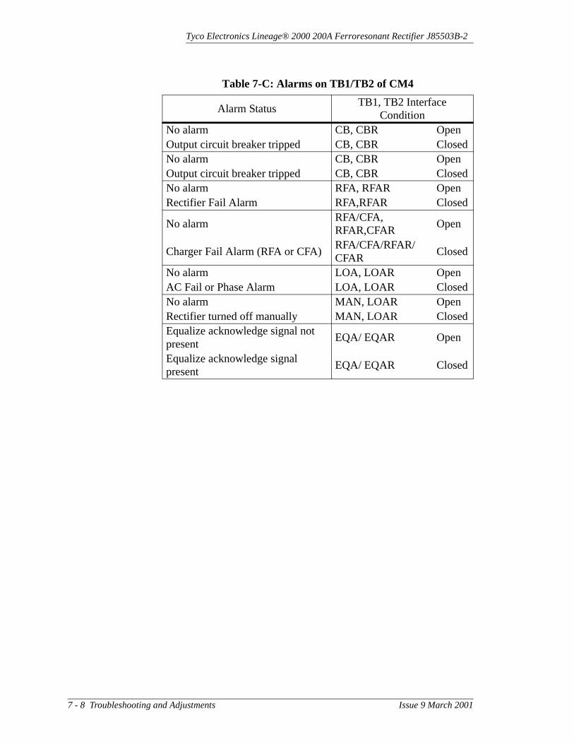
Tyco Electronics Lineage® 2000 200A Ferroresonant Rectifier J85503B-2
Table 7-C: Alarms on TB1/TB2 of CM4
Alarm StatusTB1, TB2 Interface
ConditionNo alarm CB, CBR OpenOutput circuit breaker tripped CB, CBR ClosedNo alarm CB, CBR OpenOutput circuit breaker tripped CB, CBR ClosedNo alarm RFA, RFAR OpenRectifier Fail Alarm RFA,RFAR Closed
No alarmRFA/CFA, RFAR,CFAR
Open
Charger Fail Alarm (RFA or CFA)RFA/CFA/RFAR/CFAR
Closed
No alarm LOA, LOAR OpenAC Fail or Phase Alarm LOA, LOAR ClosedNo alarm MAN, LOAR OpenRectifier turned off manually MAN, LOAR ClosedEqualize acknowledge signal not present
EQA/ EQAR Open
Equalize acknowledge signal present
EQA/ EQAR Closed
7 - 8 Troubleshooting and Adjustments Issue 9 March 2001

Tyco Electronics Lineage® 2000 200A Ferroresonant Rectifier J85503B-2
Table 7-D: Controls on TB1/TB2 of CM4
Control Status TB1/TB2 Interface ConditionNo controlRectifier restart initiated
Open circuit between RS, RSRMomentary short applied to RS, RSR
No controlRectifier shuts downRectifier turns On after being off
Open circuit between TR, TRRShort applied between TR, TRRShort removed from TR, TRR
No controlRectifier shuts downRectifier off
Open short between HV, TRRShort applied between HV, TRRShort removed from HV, TRR
No controlRectifier in equalize modeRectifier in float after being in equalize
Open circuit between EQL, EQLRShort applied between EQL. EQLRShort removed from EQL, EQLR
No control 48V rectifier turns on48V rectifier shuts down after being On
Open circuit between RM48, TRRShort applied between RM48, TRRShort removed from RM48, TRR
No control 24V rectifier turns on24V rectifier shuts down after being On
Open circuit between RM24, TRRShort applied between RM24, TRRShort removed from RM24, TRR
Issue 9 March 2001 Troubleshooting and Adjustments 7 - 9

Tyco Electronics Lineage® 2000 200A Ferroresonant Rectifier J85503B-2
Table 7-E: Signals on TB3 of CM4
Alarm Status TB3 Interface ConditionNo test RFAT OpenRFA alarm generated without turning the rectifier off
RFAT Closed
No alarm ACF, ACFR OpenAC has failed ACF, ACFR ClosedNo alarm LCA, LCAR Open*Load share enable; output current less than 3 amperes
LCA, LCAR Closed
No alarm LSF, LSFR Open*Load share enabled; rectifier not load sharing
LSF, LSFR Closed
No connectionLS Standard Load Share not connected
ConnectionLS Standard Load Share connected (Must also be enabled via S1.9 on CM2)
No connectionNLS Special Application Load Share not connected
Connection
NLS Special Application Load Share not connected (Must also be enabled via S2.7 on CM4)
* Load sharing applies only to the -48V rectifier.
7 - 10 Troubleshooting and Adjustments Issue 9 March 2001
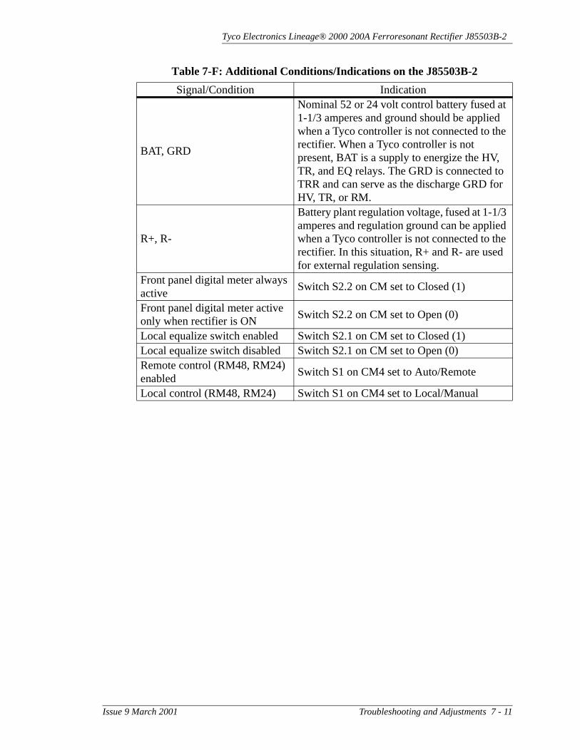
Tyco Electronics Lineage® 2000 200A Ferroresonant Rectifier J85503B-2
Table 7-F: Additional Conditions/Indications on the J85503B-2
Signal/Condition Indication
BAT, GRD
Nominal 52 or 24 volt control battery fused at 1-1/3 amperes and ground should be applied when a Tyco controller is not connected to the rectifier. When a Tyco controller is not present, BAT is a supply to energize the HV, TR, and EQ relays. The GRD is connected to TRR and can serve as the discharge GRD for HV, TR, or RM.
R+, R-
Battery plant regulation voltage, fused at 1-1/3 amperes and regulation ground can be applied when a Tyco controller is not connected to the rectifier. In this situation, R+ and R- are used for external regulation sensing.
Front panel digital meter always active
Switch S2.2 on CM set to Closed (1)
Front panel digital meter active only when rectifier is ON
Switch S2.2 on CM set to Open (0)
Local equalize switch enabled Switch S2.1 on CM set to Closed (1)Local equalize switch disabled Switch S2.1 on CM set to Open (0)Remote control (RM48, RM24) enabled
Switch S1 on CM4 set to Auto/Remote
Local control (RM48, RM24) Switch S1 on CM4 set to Local/Manual
Issue 9 March 2001 Troubleshooting and Adjustments 7 - 11

Tyco Electronics Lineage® 2000 200A Ferroresonant Rectifier J85503B-2
Adjustments This section includes procedures to check fuses (Clear RFA and FA), calibrate the meter, adjust the current limit, and set the internal selective high voltage shutdown (ISHVSD) for rectifiers without controllers. It may be necessary to remove the rectifier from service before completing these procedures.
Clear RectifierFailure Alarm
(RFA)
A fuse alarm (FA) may be present with the RFA alarm.
1. Observe and record the status of the fuses in the plant controller. If the controller has an efficiency algorithm, disable this feature.
2. Turn the rectifier Power switch Off.
3. If any of the following fuses are blown, remove the rectifier from service and replace fuse(s) with one of the same type and capacity.
– Alarm fuses F1, F2, and F3 on CM1– Output filter capacitor fuses F1, F2, F3, F4, F5.
4. Restore the rectifier to service.
5. If the rectifier started, minor alarm retired on controller, and the rectifier RFA light extinguished, then the RFA problem has been cleared. Otherwise, continue with the following procedures.
The rectifier voltage may be too high.
1. Observe and record the rectifier output voltage, Rect V, and plant float voltage, Plt V. The rectifier voltage is normally greater than the plant voltage by an amount equal to the lead drop between rectifier and batteries, less than 2 volts. Adjusting the plant voltage makes a corresponding adjustment in the rectifier voltage.
2. If the rectifier output voltage is greater than the plant float voltage by more than the expected lead drop, then use the following procedures:
a. Holding the meter selector switch in the Plt V position, turn the Float Adj potentiometer counterclockwise to lower the output voltage to the correct value.
7 - 12 Troubleshooting and Adjustments Issue 9 March 2001

Tyco Electronics Lineage® 2000 200A Ferroresonant Rectifier J85503B-2
b. If the rectifier Float Adj potentiometer can be used to adjust the voltage to the correct level, the RFA problem has been cleared. Otherwise, continue with the following procedures.
3. If the rectifier output voltage is less than the plant voltage and/or all rectifiers shut down, then use the following procedures.
a. If the CM2 board has not been replaced, then replace it at this time.
b. If the rectifier started, minor alarm retired on controller, and the rectifier RFA light extinguished, then the RFA problem has been cleared. Otherwise, continue with the following procedures.
4. If replacing the CM2 board does not clear the problem, then the outputs from T1 and T2 are probably unbalanced. Try the following:
a. Check the wiring to the thyristors (see Figure 8-1).
b. Check for defective thyristors. If defective, replace.
5. Verify that the controller’s high voltage shutdown circuit is operating properly (see the controller manual).
Clear Fuse Alarm(FA)
1. If the circuit breaker (CB1) is tripped, restore the rectifier to service.
2. If CB1 did not trip, check alarm fuses F1, F2, and F3 on CM1. These fuses are accessible by opening the door of the rectifier. CM1 is near the output filter capacitors.
3. If the F2 or F3 alarm fuse is blown, check for possible trouble and replace the fuse.
4. If the F1, F2, F3, F4, or F5 capacitor fuse or F1 alarm fuse on CM1 is blown, check for a shorted output capacitor. Remove the rectifier from service to replace any shorted capacitor and/or blown fuse.
Issue 9 March 2001 Troubleshooting and Adjustments 7 - 13

Tyco Electronics Lineage® 2000 200A Ferroresonant Rectifier J85503B-2
Calibrate CM3Digital Meter
Calibration is not feasible unless the test meter has an accuracy of ± 0.02 percent or better.
1. Loosen the locking screws and open the front door of the rectifier.
2. Locate the CM3 digital meter board on the inside of the front door.
WarningExercise extreme care when removing the CM3 board from the support standoffs.
The CM3 board can be calibrated without removing the board from the support standoffs.
3. Locate the R15 potentiometer on the meter board (see Figure 7-1). R15 is easily accessible on the component side of the board.
4. Adjust the load so that the rectifier delivers approximately 100 amperes, 50% of its rated current capacity.
5. Connect a DMM, set on the dc millivolt scale, across the 329 test points E25/E26. See Figure 6-2.
6. Observe the DMM and record the rectifier’s shunt voltage. The shunt is rated 250A/50mV=5A/mV, which means that each millivolt of voltage drop across the shunt indicates 5A of output current.
7. Convert the DMM shunt voltage reading to amperes. For example, if the DMM reads 20mV, then 20mV x 5A/mV = 100A of output current.
8. Compare the amperes calculated in Step 7 with the digital display of the meter while the switch is in the AMPS position. If the digital display is not between ±2% ±2A of the amperes calculated in Step 7, calibrate the CM3 card via its R15 potentiometer.
Table 7-G provides digital meter tolerances.
Table 7-G: Digital Meter Tolerance
Switch Position ToleranceRect V ± 0.1 volt
7 - 14 Troubleshooting and Adjustments Issue 9 March 2001

Tyco Electronics Lineage® 2000 200A Ferroresonant Rectifier J85503B-2
Adjust CurrentLimit
Off Line Adjustment: Use the Current Limit Test (Off Line) to verify that the current limit circuit needs adjustment, before continuing with this procedure.
Amps ± 2.5% of reading ± 2 amperes** To compare, measure the shunt voltage. 1mV of shunt voltage indicates
5 amperes of output current. For example, the shunt voltage should be 40 mV at full load (200 amperes). At 125% of full load (250 amperes), the shunt voltage should be 50 mV.
Table 7-G: Digital Meter Tolerance
Switch Position Tolerance
Figure 7-1: Adjustment Potentiometer on CM3
Digital Meter Potentiometer
Issue 9 March 2001 Troubleshooting and Adjustments 7 - 15

Tyco Electronics Lineage® 2000 200A Ferroresonant Rectifier J85503B-2
In steps (4) and (5) of the Current Limit Test in Section 6, if Vout is not within the required range, adjust R88 on CM2 (see Figure 6-3) until a correct voltage reading is obtained.
On Line Adjustment: Use the Current Limit Test (On Line), Section 6, to verify that the current limit circuit needs adjustment, before continuing with this procedure.
1. Hold the Rect Test switch in the full load (FL) position and observe the output current.
2. If the output current is not within 200-202A, hold the Rect Test switch in the full load (FL) position and adjust the current limit potentiometer R88 on CM2, (see Figure 6-3), until the rectifier delivers 200-202A.
WarningThe rectifier is designed to provide 200 amperes. If the current limit is set beyond this rating, the unit may overheat, and its useful life may be severely shortened.
ISHVSD in Plants Without a Controller
To avoid overvoltage conditions on the actual battery plant loads, perform this procedure with the rectifier disconnected from the battery. A portable test load that can supply at least 220A, 10 percent above the rectifier’s current rating, is required.
1. Connect the test load as specified in Section 6. Then restore ac power to the rectifier.
2. Turn the Power switch On.
3. Turn the CB1 circuit breaker On.
4. Adjust test load to 220A or greater. Read load current on control panel meter.
5. Open switch contacts S3.7 and S3.8 on CM2.
6. Adjust the Float Adj potentiometer to obtain a rectifier voltage of 55.0 (29.0) ± 0.6 volts. Read voltage on control panel meter by holding meter switch in Rect V position. The rectifier should shut down.
7. Decrease the load to less than 2 percent and restart the rectifier. The rectifier should start and operate normally. If
7 - 16 Troubleshooting and Adjustments Issue 9 March 2001

Tyco Electronics Lineage® 2000 200A Ferroresonant Rectifier J85503B-2
the rectifier does not operate properly, refer to “Diagnostics” section.
8. Turn on dip switch S3.7 on CM2, restart the rectifier, and adjust the load to at least 10 percent, 20A.
Optional: To verify proper operation of the ISHVSD circuit, do the following:
a. Adjust the Float Adj potentiometer to obtain 56 (29.5) ± 0.5 volts. Read voltage on control panel meter by holding meter switch in the Rect V position. The rectifier should shut down.
b. Open switch contact S3.7, close switch contact S3.8, and restart rectifier.
c. Adjust the Float Adj potentiometer to obtain 57 (30.0) ±0.5 volts. Read voltage on control panel meter by holding meter switch in the Rect V position. The rectifier should shut down.
d. Close switch contact S3.7, and restart rectifier.
e. Adjust the Float Adj potentiometer to obtain 58 (30.5) ±0.5 volts. Read voltage on control panel meter by holding meter switch in the Rect V position. The rectifier should shut down.
9. Set ISHVSD to desired level.
10. Remove ac power to the rectifier at the ac service panel, and disconnect the test load.
11. Reconnect the rectifier to the battery.
Issue 9 March 2001 Troubleshooting and Adjustments 7 - 17

Tyco Electronics Lineage® 2000 200A Ferroresonant Rectifier J85503B-2
Restore Rectifier to Service
1. Set the ac supply and rectifier controls as shown in Table 7-H.
2. If the rectifier voltage was NOT at the desired float voltage before it was turned off, rotate the Float Adj potentiometer fully counterclockwise.
3. At the ac service panel, install the ac fuses or turn the ac input circuit breaker On.
4. To bring the rectifier into service:
a. Turn the rectifier Power switch On. The green Power LED must light. Wait 10 seconds.
b. Hold the meter selector switch in the Rect V position, and use a small screwdriver to turn the Float Adj potentiometer clockwise until the digital meter reads approximately battery voltage.
c. Turn the rectifier Power switch Off and immediately (within 5 seconds) turn circuit breaker CB1 on (up).
5. At the rectifier, connect the control cable connector J5A.
6. At the plant controller, install the REG fuse associated with the rectifier that is being restored to service.
7. Turn the rectifier Power switch On.
8. Close the rectifier front door and secure the locking screws.
Table 7-H: Control Settings Prior to Restoring a Rectifier to Service
Controls Position/StatusAssociated ac circuit breaker or fuses at the ac service distribution panel
Off or fuses removed and holders tagged “Out of Service”
Rectifier Power switch Off (down)Rectifier CB1 circuit breaker Off (down)Rectifier REG fuse in the plant controller
Removed
7 - 18 Troubleshooting and Adjustments Issue 9 March 2001

Tyco Electronics Lineage® 2000 200A Ferroresonant Rectifier J85503B-2
9. Adjust the rectifier to float voltage per Section 6.
10. If the rectifier is installed in a microprocessor-controlled plant that has an efficiency algorithm feature, enable this feature. (See the controller manual for instructions).
Preventive Maintenance
We recommend that all maintenance be done OFF LINE, with all ac input and dc bus voltages disconnected from the rectifier being serviced. Follow the instructions in “Disconnecting a Rectifier” at the beginning of this section. At 12-month intervals, check torque on various connections, such as ac input and dc output connectors. See Tables 8-A and 8-B for torque requirements. OBSERVE SAFETY PRECAUTIONS IF WORKING IN A LIVE PLANT.
Check calibration of the rectifier’s digital meter.
Issue 9 March 2001 Troubleshooting and Adjustments 7 - 19


Tyco Electronics Lineage® 2000 200A Ferroresonant Rectifier J85503B-2
8 Replacing Components and Circuit Modules
General Considerations for Replacing Components
Only disassembly procedures are given in this section. Some points are common to all rectifier disassembly work.
Reinstallation procedures are usually the exact reverse of removal procedures (i.e., follow the removal procedures in reverse order to reinstall the component). Specific instructions are given when this does not apply exactly, or where special considerations or precautions must be taken during reinstallation. Applicable portions of Section 5, Installation, may be helpful. Portions of Section 6, Testing, can be used after reinstallation to verify proper operation of the rectifier.
NoteRead all of the considerations below before using the rectifier disassembly procedures.
• Take proper precautions against accidental personal injury or damage to equipment. Observe warnings given in Section 4, Safety, in addition to the following admonishment before undertaking any disassembly or reinstallation procedure on a rectifier.
DANGERThe following procedures MUST be performed only on a rectifier completely disconnected from the plant battery buses, AND with no input from the ac service panel connected to the rectifier. The plant control cable, J5A must also be disconnected from the CM4 board.
Issue 9 March 2001 Replacing Components and Circuit Modules 8 - 1

Tyco Electronics Lineage® 2000 200A Ferroresonant Rectifier J85503B-2
• The ac service and dc battery buses can be safely disconnected from the rectifier by following the steps in Section 7, “Disconnecting a Rectifier.” All work must be done carefully because you are working with live cables at battery bus potentials and current capabilities. The disconnected charge battery and charge ground connectors must be taped adequately to prevent them from contacting each other or any other metal surface. Alternatively, the dc battery cables from the rectifier can be disconnected at the plant charge battery and charge ground buses.
• Always make note of the lead connection points (termination points) before unsoldering or disconnecting them to insure trouble-free reinstallation. This includes potentiometer leads, or the solderless, quick-disconnect type connections used on circuit boards, relays, inductors, transformers, and wire bundles.
• Always disconnect quick-disconnect connections by pulling straight apart with pliers to avoid bending or breaking the tabs. Do not pull on wire. Always remember to save hardware, thermal pads, and other items in a convenient place for reassembly.
• DC capacitors can be examined to see if they have “blown” (i.e., vented) due to voltage breakdown failure. A small hole in the capacitor top, called a “blowhole,” is plugged in a new or good capacitor, but is empty (blown out) in a failed unit. Some capacitor blowholes cannot be viewed directly until removed or almost removed from the rectifier. A dental-type mirror aids in viewing these capacitors' blowholes before disassembly. Tyco recommends that all dc capacitors in a rectifier be replaced whenever any one of them blows.
• Most component removals are straightforward and obvious. Therefore, these procedures can be used as a guide by qualified service personnel, rather than as step-by-step procedures. For example, you may prefer to remove a part not called for in order to make more room for access to a component being replaced.
Tables 8-A and 8-B provide the reassembly torquing requirements for the electrical and mechanical connections in the rectifier. Torque values are given in inch-pounds or foot-pounds and Newton-meters. Use these values unless otherwise directed in the procedures.
8 - 2 Replacing Components and Circuit Modules Issue 9 March 2001

Tyco Electronics Lineage® 2000 200A Ferroresonant Rectifier J85503B-2
General notes for Table 8-A:
• Slotted machine screws should be the pan-head type.• Slotted machine and hex cap screws should be SAE Grade 2
steel or equivalent.• Socket cap screws should have 100,000 psi minimum
tensile strength.• Locking means is only required for connections subject to
vibration. Belville-type washers or jam nuts are preferred.• Ferrous screws and washers should have a corrosion
protective finish.• For tapped copper bars less than 1/4-inch thick, use slotted
No. 8, No. 10, or 1/4-inch machine screws to minimize applicable torque. When larger size screws are required, provide captive-type steel nuts or reduce torque.
• Torque recommendations are also suitable for all non-ferrous fasteners, except aluminum.
• Where the application permits, use hex cap screws.
Table 8-A: Minimum Torque for Electrical Connections
Screw Size
Torque Values in In-Lb (or Ft-Lb)/Nm
Wire Connections Head Tightened Nut Tightened
Slotted Machine
Hex /Socket Cap
Slotted Machine
Hex /Socket Cap
Slotted Machine/ Hex
CapSocket Cap
In-Lb Nm In-Lb Nm In-Lb Nm In-Lb Nm In-Lb Nm In-Lb Nm
8-32 15 /2 15 2 19 2 19 2 19 2 23 2.3
10-24 21 2.5 21 2.5 27 3 27 3 27 3 33 4
1/4-20 50 5.5 50 5.5 65 8 65 8 65 8 80 9
5/16-18 - - 100 11 - - 135 15 135 15 165 19
3/8-16 - - 108 20 - - 240 27 240 27 290 33
7/16-14 - - 280 32 - - 385 44 385 44 465 55
1/2-13 - - 500 56 - - 585 66 585 66 710 80
5/8-11 - - (71) 96 - - (97) 131 (97) 131 (118) 160
3/4-10 - - (125) 170 - - (172) 233 (172) 233 (209) 283
Issue 9 March 2001 Replacing Components and Circuit Modules 8 - 3

Tyco Electronics Lineage® 2000 200A Ferroresonant Rectifier J85503B-2
Replacing Components
DANGERThe following procedures MUST be performed only on a rectifier completely disconnected from the plant battery buses, AND with no input from the ac service panel connected to the rectifier. The plant control cable, J5A should also be disconnected from the CM4 board.
1. Remove the rectifier from service following the procedure in Section 7, “Disconnecting a Rectifier.”
2. After replacing components, restore the rectifier to service following the procedure in Section 7, “Restore Rectifier to Service.”
3. Remove plastic shields where necessary to access components in the J85503B-2 rectifier.
4. Refer to Figures 2-3 and 8-1 for component locations.
Table 8-B: Torque and Minimum Yield Strength Values for Mechanical Connections (Using Hex Head Cap
Screws)
Cap Screw Diameter (Inch)
Min. Yield Strength
Torque
Ft-Lb UNRC
Nm
1/4 57,000 6 8
3/16 57,000 12 16
3/8 57,000 22 30
7/16 57,000 35 47
1/2 57,000 54 73
9/16 57,000 77 104
5/8 57,000 107 145
3/4 57,000 190 257
7/8 36,000 193 261
1 36,000 290 393
1-1/8 36,000 410 556
1-1/4 36,000 580 786
1-3/8 36,000 760 1030
1-1/2 36,000 1010 1370
8 - 4 Replacing Components and Circuit Modules Issue 9 March 2001

Tyco Electronics Lineage® 2000 200A Ferroresonant Rectifier J85503B-2
Thyristors(Q1, Q2)
1. Remove the wires attached to the thyristor. Note their position for reinstallation. The T4013NK thyristors, originally in the rectifier, use a beryllium ceramic. If the case is cracked, the manufacturer (Semiconductors Ltd., A Raytheon Company) recommends the component be handled with gloves, placed in a plastic bag, and sealed before discarding. The replacement part does not use a beryllium ceramic.
Figure 8-1: Component Locations
DC Capacitors(Optional)
DC Inductor L4Behind CircuitBreaker(Optional)
DiodesCR1 to CR4on Heat Sink
DC Capacitors
ThyristorsQ1 and Q2
DC Inductor L3
Main TransformerBehind Cover Plate
AC InductorsL1 and L2and AC CapacitorsBehind Heat Sink
Issue 9 March 2001 Replacing Components and Circuit Modules 8 - 5

Tyco Electronics Lineage® 2000 200A Ferroresonant Rectifier J85503B-2
2. Remove the two nuts that secure the thyristor to the heat sink. Save the nuts and the thermal pad from under the thyristor.
3. When reinstalling a new thyristor, use the hardware and thermal pad (DP102 comcode 403208242) saved in Step (2). Note that the small gate terminal always faces down. Torque the mounting nuts to 10 in-lb. Reconnect the wires to the new thyristor.
Diode Heat SinkAssemblies
1. Remove the nuts securing the pigtail of the diode to be replaced from the power transformer.
2. Use a meter with a diode test function (or measure the forward and backward resistances of the diode) to determine if the diode is good. A good diode should measure at least 50 ohms in both directions, and one direction should measure at least 50 times the other. The larger resistance is the back resistance, and the smaller is the forward resistance. Most diodes that fail do so by shorting (i.e. they will measure shorted or almost shorted in both directions).
3. If the diode checked bad, replace it. If the diode checked good, reinstall it.
4. Remove the nut on the back side of the diode. Save the thermal pad and nut. Cut cable tie securing the pigtail lead.
5. Reinstall diode with thermal pad. Dress pigtail lead away from any sharp corners. Torque diode nut to 300 in-lbs. Torque pigtail connection to transformers to 65 in-lb. Reinstall cable ties.
DC Capacitors(C7 through C12)
DANGERDC capacitors may be charged even with power disconnected from the rectifier. If filter capacitor fuses have blown, capacitors will be charged. Always check all of the dc capacitor terminals (observe polarity) with a voltmeter before performing this procedure, and discharge capacitors safely, if necessary. Wait at least 5 minutes after shutting down ac and CB1 before working on capacitors or associated buswork.
8 - 6 Replacing Components and Circuit Modules Issue 9 March 2001

Tyco Electronics Lineage® 2000 200A Ferroresonant Rectifier J85503B-2
1. DC Capacitors C5 through C9 are located behind the capacitor bus bars. The bus bars are mounted directly to the capacitors by the capacitor terminal screws. In order to remove a capacitor, remove fuse board CM1, the capacitor terminal screws, mounting screws, and the screw supporting the fuse assembly. Note that this completely frees the capacitor bus bar in question.
2. Remove the capacitor from its clamp by pulling toward you on the capacitor.
3. Replace the capacitor by pushing it into the clamp with the positive terminal toward the inside.
NoteAll output capacitors should be replaced if any are being replaced.
4. Replace the negative bus bar. Tighten the mounting screws first and then the capacitor terminal screws.
5. Replace the fuse assembly. Replace fuse if required.
CB1 CircuitBreaker
1. Remove the output cables to the rectifier.
2. Remove the bolts securing the input bus bar to the circuit breaker.
3. Support the breaker and remove the four screws securing the breaker to the side upright. Note that there are two alarm connections attached to the rear of the breaker. Remove these once the breaker is free.
4. Reinstall in reverse order.
DC Inductor(L3, L4)
NoteBefore replacing a dc inductor (L3 or L4), remove the circuit breaker.
1. Remove the electrical connection of the inductor to be replaced.
Issue 9 March 2001 Replacing Components and Circuit Modules 8 - 7

Tyco Electronics Lineage® 2000 200A Ferroresonant Rectifier J85503B-2
2. While supporting the weight of the inductor, remove all four of the mounting nuts that secure it to the frame. Reinstall in reverse order.
Contactor Relay(K1)
1. Remove all six of the heavy gauge (input and output) wires from K1.
2. Remove the five smaller gauge wires from K1 and identify their position for reinstallation.
3. Remove the three mounting screws to free K1 from the rear wall.
4. Install the new relay in the reverse order. Torque to 25 in-lbs.
AC Inductors(L1, L2)
1. Remove the cables and wires from both terminals of the inductor.
2. While supporting the weight of the inductor, remove the inductor from the rectifier.
3. Install the new inductor in the reverse order.
AC Capacitors(C1 - C6,
C13 and C14)
1. Remove the quick-disconnect receptacles from the capacitor and note their positions.
2. Remove the screws securing the capacitor clamp and capacitor to the mounting plate.
3. Loosen the clamp on the capacitor and remove.
4. Reinstall the capacitor in the reverse order.
MainTransformers
(T1, T2)
1. Remove the rectifier from the line up and lay it on its back.
2. Remove all of the cables from the transformers.
3. To access the transformer mounting screws, remove the kickplate (five screws) from the bottom of the rectifier frame and side plates.
8 - 8 Replacing Components and Circuit Modules Issue 9 March 2001

Tyco Electronics Lineage® 2000 200A Ferroresonant Rectifier J85503B-2
4. Remove the four transformer mounting nuts, from under the T1/T2 mounting bracket, that secure the transformer.
5. While supporting the transformer with adequate lifting equipment (at least 1000 lb), lift the transformer outward.
6. Reinstall the new transformer in the reverse order.
Handling Circuit Modules
The following guidelines describe an electrostatic discharge (ESD) prevention method that is consistent with the proper handling and protection of circuit packs in a central office or outside plant environment. These guidelines satisfy the minimum requirements for all three ESD-sensitive classifications (I, II, III). All circuit packs in these classes are handled in the same manner, regardless of sensitivity. Factory packaging provides shielding in the rare instances when it is necessary.
Electrostatic Discharge WarningGrounded antistatic wrist straps must be worn for all circuit pack handling. The alligator clip connector of the wrist strap must be connected to a bare metal frame ground. The wrist strap must contact the skin and is not to be worn over clothing. At least once every week of use, verify that the resistance between the wrist strap and its connector plug is 1 milliohm ±10%. If a static-sensitive pack has already been found faulty, do not ignore requirements for handling static-sensitive packs. Continued mishandling may create other, more serious, problems with the pack.
• Assume all circuit packs containing electronic (solid-state) components can be damaged by ESD.
• When handling circuit packs (storing, inserting, removing, etc.) or when working on the backplane, always use the appropriate grounding procedure: either a wrist strap connected to ground or, when standing, a heel strap with a grounded dissipative floor mat.
• A grounded person must never hand an unprotected circuit pack to an ungrounded person. A static discharge from the ungrounded person through the circuit pack to the grounded person could cause an electrostatic discharge failure. All persons and equipment at a work location must be at the same common ground potential to be static safe.
Issue 9 March 2001 Replacing Components and Circuit Modules 8 - 9

Tyco Electronics Lineage® 2000 200A Ferroresonant Rectifier J85503B-2
• Handle all circuit packs by the faceplate or latch and by the top and bottom outermost edges. Never touch the components, conductors, or connector pins.
• Do not rub or wipe circuit packs to clean them unless you and the circuit pack are at the same ground potential.
• Observe warning labels on bags and cartons. Whenever possible, do not remove circuit packs from antistatic bags or cartons until ready to insert into the rectifier. Otherwise, open all circuit packs at a static-safe work position with wrist straps and dissipative table mats.
• Upon removal from the rectifier, immediately put circuit packs into antistatic packages. Always store and transport circuit packs in antistatic packaging. Shielding is not required unless specified.
• Keep all static-generating materials away from all circuit packs. These materials include common plastics such as food wrappers, clear plastic bags, styrofoam containers, packing material, drinking cups, notebooks, and nonconductive plastic solder suckers. The insulation on small hand tools does not represent a static hazard.
• Keep adhesive tape (Scotch, masking, etc.) away from static-sensitive devices.
• When soldering static-sensitive semiconductor devices, the soldering iron must be grounded to the work table which must also be earth grounded.
• Do not wax the equipment aisles in central offices.• Whenever possible, maintain relative humidity above the
20-percent level.
Replacing Circuit Modules
This procedure gives instructions for replacing the circuit modules.
WarningMinimize electrostatic discharge when handling circuit modules. Do not connect or disconnect circuit modules with voltages present or equipment damage may occur. AC voltages may be present when the rectifier Power switch is Off.
CM1 Fuse Board 1. Turn the rectifier Power switch Off.
2. Turn the rectifier CB1 circuit breaker Off (down).
8 - 10 Replacing Components and Circuit Modules Issue 9 March 2001

Tyco Electronics Lineage® 2000 200A Ferroresonant Rectifier J85503B-2
3. At the ac service panel supplying power to the rectifier, remove the input fuses assigned to the rectifier, or turn the circuit breaker Off.
4. At the plant controller, remove the REG fuse associated with the rectifier.
5. At the rectifier, loosen the locking screws and open the door.
6. Measure the voltage on each of the C5 through C9 capacitors. Discharge to below 20 volts before proceeding.
CautionSupport the CM1 fuse board with your hands when connecting and disconnecting the cables, or damage to the board may result. Do NOT disconnect cables by pulling the cable.
7. Disconnect control cable connector J5A from the CM4 board by unlatching first, then pulling the connector.
8. Remove all cables from CM1 by unlatching first, then pulling the cable connector.
9. Remove CM1 from its four support standoffs by using a small flat-bladed screwdriver to push in the latches on each standoff.
10. Position the new CM1 over the four support standoffs. Verify that each latch snaps and locks in place.
11. Reconnect all cables that were disconnected in step (7).
12. If the rectifier is to be restored to service, refer to Section 7, “Restore Rectifier to Service.”
CM2 ControlBoard
Minimize electrostatic discharge when handling circuit modules. Observe all warnings in Section 4, Safety.
1. Turn the rectifier Power switch Off.
2. Turn the rectifier CB1 circuit breaker off (down).
Issue 9 March 2001 Replacing Components and Circuit Modules 8 - 11

Tyco Electronics Lineage® 2000 200A Ferroresonant Rectifier J85503B-2
3. At the ac service panel supplying power to the rectifier, remove the input fuses assigned to the rectifier, or turn the circuit breaker off.
4. At the plant controller, remove the fuse REG fuse associated with the rectifier.
5. At the rectifier, loosen the locking screws and open the door.
CautionSupport the CM2 control board with your hands when connecting and disconnecting the cables, or damage to the board may result. DO NOT disconnect cables by pulling the cable.
6. Disconnect control cable connector J5A from the CM4 board by unlatching first, then pulling the connector.
7. Disconnect JT2, JT3, J3A, J4, J5, J6, and J7 connecting cables from CM2.
8. Remove CM2 from the six support standoffs by using a small flat-bladed screwdriver to push in the latches on each standoff.
9. Position the new CM2 board over the six standoffs. Verify that each latch snaps and locks in place.
10. Reconnect JT2, JT3, J3A, J4, J5, J6, and J7 connecting cables to CM2.
11. If the rectifier is to be restored to service, refer to Section 7, “Restore Rectifier to Service.”
CM3 DigitalMeter Board
Minimize electrostatic discharge when handling circuit modules. Observe all warnings in Section 4, Safety.
1. Turn the rectifier Power switch Off.
2. Turn the rectifier CB1 circuit breaker off (down).
3. At the ac service panel supplying power to the rectifier, remove the input fuses assigned to the rectifier, or turn the circuit breaker Off.
8 - 12 Replacing Components and Circuit Modules Issue 9 March 2001

Tyco Electronics Lineage® 2000 200A Ferroresonant Rectifier J85503B-2
4. At the plant controller, remove the fuse REG fuse associated with the rectifier.
5. At the rectifier, loosen the locking screws and open the door.
CautionSupport the CM3 control board with your hands when connecting and disconnecting the cables, or damage to the board may result. DO NOT disconnect cables by pulling the cable.
6. Disconnect control cable connector J5A from the CM4 board by unlatching first, then pulling the connector.
7. Disconnect the connecting cables from CM3.
8. Remove CM3 from the two support standoffs by using a small flat-bladed screwdriver to push in the latches on each standoff. Remove the one screw holding CM3 in place.
9. Position the new CM3 board over the two standoffs. Replace the screw. Verify that each latch snaps and locks in place.
10. Reconnect connecting cables to CM3.
11. Check calibration of rectifier meter per Section 7, “Calibrate CM3 Digital Meter.”
12. If the rectifier is to be restored to service, refer to Section 7, “Restore Rectifier to Service.”
CM4 InterfaceBoard
Minimize electrostatic discharge when handling circuit modules. Observe all warnings in Section 4, Safety.
1. Turn the rectifier Power switch Off.
2. Turn the rectifier CB1 circuit breaker Off (down).
3. At the ac service panel supplying power to the rectifier, remove the input fuses assigned to the rectifier, or turn the circuit breaker Off.
4. At the plant controller, remove the fuse REG fuse associated with the rectifier.
Issue 9 March 2001 Replacing Components and Circuit Modules 8 - 13

Tyco Electronics Lineage® 2000 200A Ferroresonant Rectifier J85503B-2
5. At the rectifier, loosen the locking screws and open the door.
CautionSupport the CM4 control board with your hands when connecting and disconnecting the cables, or damage to the board may result. DO NOT disconnect cables by pulling the cable.
6. Disconnect control cable connector J5A from the CM4 board by unlatching first, then pulling the connector.
7. Disconnect the connecting cables from CM4.
8. Remove CM4 from the support standoffs by using a small flat-bladed screwdriver to push in the latches on each standoff.
9. Position the new CM4 board over the standoffs. Verify that each latch snaps and locks in place.
10. Reconnect connecting cables to CM4.
11. If the rectifier is to be restored to service, refer to Section 7, “Restore Rectifier to Service.”
CM5 or CM6Snubber Board
1. Remove the quick-disconnect connectors from the board.
2. Push in on the plastic locking tabs to free the board.
3. Remove any screws holding the board in place.
4. Reinstall in reverse order.
CM7Transformer
Board
Minimize electrostatic discharge when handling circuit modules. Observe all warnings in Section 4, Safety.
1. Turn the rectifier Power switch Off.
2. Turn the rectifier CB1 circuit breaker Off (down).
3. At the ac service panel supplying power to the rectifier, remove the input fuses assigned to the rectifier, or turn the circuit breaker Off.
8 - 14 Replacing Components and Circuit Modules Issue 9 March 2001

Tyco Electronics Lineage® 2000 200A Ferroresonant Rectifier J85503B-2
4. At the plant controller, remove the fuse REG fuse associated with the rectifier.
5. At the rectifier, loosen the locking screws and open the door.
CautionSupport the CM7 control board with your hands when connecting and disconnecting the cables, or damage to the board may result. DO NOT disconnect cables by pulling the cable.
6. Disconnect control cable connector J5A from the CM4 board by unlatching first, then pulling the connector.
7. Disconnect the connecting cables from CM7.
8. Remove CM7 from any support standoffs by using a small flat-bladed screwdriver to push in the latches on each standoff. Remove the two screws holding CM7 in place.
9. Position the new CM7 board over the two screw standoffs. Verify that each latch snaps and locks in place. Restore the two screws.
10. Reconnect connecting cables to CM7.
11. If the rectifier is to be restored to service, refer to Section 7, “Restore Rectifier to Service.”
Issue 9 March 2001 Replacing Components and Circuit Modules 8 - 15


Tyco Electronics Lineage® 2000 200A Ferroresonant Rectifier J85503B-2
9 Product Warranty
A. Seller warrants to Customer only, that:
1. As of the date title to Products passes, Seller will have the right to sell, transfer, and assign such Products and the title conveyed by Seller shall be good;
2. Upon shipment, Seller’s Manufactured Products will be free from defects in material and workmanship, and will conform to Seller’s specifications or any other agreed-upon specification referenced in the order for such Product;
3. With respect to Vendor items, Seller, to the extent permitted, does hereby assign to Customer the warranties given to Seller by its Vendor of such Vendor Items, such assignment to be effective upon Customer's acceptance of such Vendor Items. With respect to Vendor items recommended by Seller in its specifications for which the Vendor’s warranty cannot be assigned to Customer, or if assigned, less than Sixty (60) days remain of the Vendor’s warranty or warranty period when the Vendor’s items are shipped to Customer or when Seller submits its notice of completion of installation if installed by Seller, Seller warrants that such Vendor's items will be free from defects in material and workmanship on the date of shipment to Customer. In such an event, the applicable Warranty Period will be sixty (60) days.
B. The Warranty Period listed below is applicable to Seller’s Manufactured Products furnished pursuant to this Agreement, unless otherwise stated:
Issue 9 March 2001 Product Warranty 9 - 1

Tyco Electronics Lineage® 2000 200A Ferroresonant Rectifier J85503B-2
C. If, under normal and proper use during the applicable Warranty Period, a defect or nonconformity is identified in a Product and Customer notifies Seller in writing of such defect or nonconformity promptly after Customer discovers such defect or nonconformity, and follows Seller’s instructions regarding return of defective or nonconforming Products, Seller shall, at its option attempt first to repair or replace such Product without charge at its facility or, if not feasible, provide a refund or credit based on the original purchase price and installation charges if installed by Seller. Where Seller has elected to repair a Seller’s Manufactured Product (other than Cable and Wire Products) which has been installed by Seller and Seller ascertains that the Product is not readily returnable for repair, Seller will repair the Product at Customer’s site.
With respect to Cable and Wire Products manufactured by Seller which Seller elects to repair but which are not readily returnable for repair, whether or not installed by Seller, Seller at its option, may repair the cable and Wire Products at Customer's site.
D. If Seller has elected to repair or replace a defective Product, Customer shall have the option of removing and reinstalling or having Seller remove and reinstall the defective or nonconforming Product. The cost of the removal and the reinstallation shall be borne by Customer. With respect to Cable and Wire Products, Customer has the further responsibility, at its expense, to make the Cable and Wire Products accessible for repair or replacement and to restore the site. Products returned for repair or replacement will be accepted by Seller only in accordance with its instructions
Warranty PeriodProduct Type New Product Repaired Product
or Part*
Central Office Power Equipment 24 Months 6 Months
* The Warranty Period for a repaired Product or part thereof is as listed or, in the case of Products under Warranty, is the period listed or the unexpired term of the new Product Warranty Period, whichever is longer.
** The Warranty Period for Products ordered for Use in Systems or equipment Manufactured by and furnished by Seller is that of the initial Systems or equipment.
9 - 2 Product Warranty Issue 9 March 2001

Tyco Electronics Lineage® 2000 200A Ferroresonant Rectifier J85503B-2
and procedures for such returns. The transportation expense associated with returning such Product to Seller shall be borne by Customer. Seller shall pay the cost of transportation of the repair or replacing Product to the destination designated by Customer within the Territory.
E. The defective or nonconforming Products or parts which are replaced shall become Seller’s property.
F. If Seller determines that a Product for which warranty service is claimed is not defective or nonconforming, Customer shall pay Seller all costs of handling, inspecting, testing, and transportation and, if applicable, traveling and related expenses.
G. Seller makes no warranty with respect to defective conditions or nonconformities resulting from actions of anyone other than Seller or its subcontractors, caused by any of the following: modifications, misuse, neglect, accident, or abuse; improper wiring, repairing, splicing, alteration, installation, storage, or maintenance; use in a manner not in accordance with Seller’s or Vendor’s specifications or operating instructions, or failure of Customer to apply previously applicable Seller modifications and corrections. In addition, Seller makes no warranty with respect to Products which have had their serial numbers or month and year of manufacture removed, altered, or with respect to expendable items, including, without limitation, fuses, light bulbs, motor brushes, and the like.
THE FOREGOING WARRANTIES ARE EXCLUSIVE AND ARE IN LIEU OF ALL OTHER EXPRESS AND IMPLIED WARRANTIES, INCLUDING BUT NOT LIMITED TO WARRANTIES OF MERCHANTABILITY AND FITNESS FOR A PARTICULAR PURPOSE. CUSTOMER’S SOLE AND EXCLUSIVE REMEDY SHALL BE SELLER’S OBLIGATION TO REPAIR, REPLACE, CREDIT, OR REFUND AS SET FORTH ABOVE IN THIS WARRANTY.
© 2001 Tyco Electronics Corporation, Harrisburg, PA.All International Rights ReservedPrinted in U.S.A.
Issue 9 March 2001 Product Warranty 9 - 3