Lucent Technologies Lineage 2000 600 Ampere, -48 Volt ... · PDF file600 Ampere, -48 Volt...
164
Product Manual J85500L-1 Select Code 167-790-047 Comcode 106979073 Issue 5 January 1998 Lucent Technologies Lineage ® 2000 600 Ampere, -48 Volt Global Power System Notice: Every effort was made to ensure that the information in this document was complete and accurate at the time of printing. However, information is subject to change. © 1998 Lucent Technologies All Rights Reserved Printed in U.S.A.
-
Upload
phungkhuong -
Category
Documents
-
view
217 -
download
2
Transcript of Lucent Technologies Lineage 2000 600 Ampere, -48 Volt ... · PDF file600 Ampere, -48 Volt...
t
.
Product ManualJ85500L-1
Select Code 167-790-047Comcode 106979073Issue 5January 1998
Lucent TechnologiesLineage® 2000
600 Ampere, -48 VolGlobal Power System
Notice:Every effort was made to ensure that the information in this document was complete and accurate at the time of printingHowever, information is subject to change.
© 1998 Lucent TechnologiesAll Rights ReservedPrinted in U.S.A.
Lucent Technologies Lineage® 2000 Global Power System J85500L-1
- 2
- 3
4
7
8
9
Table of Contents
1 IntroductionGeneral Information 1 - 1Technical Support 1 - 2
USA, Canada, Puerto Rico, and the US Virgin Islands 1Central and South America 1 - 2Europe, Middle East, and Africa 1 - 3Asia Pacific Region 1 - 3
Product Repair and Return 1 - 3USA, Canada, Puerto Rico, and the US Virgin Islands 1Central and South America 1 - 3Europe, Middle East, and Africa 1 - 3Asia Pacific Region 1 - 3
Customer Service 1 - 3
2 Product DescriptionSpecifications 2 - 1
Electrical 2 - 1Physical and Thermal 2 - 2
Features 2 - 2Typical Battery Plant Description 2 - 3Global Power System Description 2 -
Rectifier Cabinet 2 - 4Supplemental Cabinet 2 - 6
Global Power System Modules 2 - Rectifier 2 - 7Controller 2 - 15CP5 Fuse Board 2 - 30Batteries 2 - 35AC Distribution 2 - 36DC Distribution 2 - 39Fuse/Circuit Breaker Alarm Module 2 - 47Battery Fuse Disconnect Panel 2 - 4Off-Line Equalize Panel 2 - 48Appearance Packages 2 - 4Boost Charge Panel 2 - 49Off-Line Equalize Panel 2 - 51
Issue 5 January 1998 Table of Contents - 1
Lucent Technologies Lineage® 2000 Global Power System J85500L-1
4
1 - 2
12
- 5
- 8
3
9
99
Front Panel Indicators 2 - 52
3 OrderingOrdering Information 3 - 1Supplementary Components 3 -Documentation 3 - 4
4 SafetySafety Statements 4 - Warning Statements And Safety Symbols 4
5 InstallationGeneral 5 - 1Installation Tools and Test Equipment 5 - Unpacking, Handling, and Frame Installation 5 - Cable Routing Strategy 5 - 3Connecting Main Rectifier Cabinet to Supplemental
Distribution Cabinet 5 - 4Connecting AC to the Global Power System 5 Installing a Rectifier 5 - 6Disconnecting a Rectifier 5 - 6Initial Start-up and Checkout 5 - 7
Electrical Testing for Rectifiers 5 - 7Background Information 5 - 7Selection of Internal Selective High Voltage
Shutdown Level 5 - 7Selection of Backup High Voltage Shutdown Level 5Enabling/Disabling of Load Sharing 5 - 8Initial Power-up and Adjustment 5 - 8
Performance Testing 5 - 11No Load Testing (NL) 5 - 12Full Load Testing (FL) 5 - 12Lamp Test 5 - 13
Adding an RSA to an Operating Plant 5 - 1Controller and Low Voltage Disconnect Setup,
Wiring, and Test 5 - 17Hardware Setup 5 - 17Operating Voltage 5 - 18Equalize Enable/Disable 5 - 18Automatic Restart Enable/Disable 5 - 1Ammeter Scale 5 - 19Battery on Discharge Threshold 5 - 1High Voltage Shutdown Thresholds 5 - 1
2 - Table of Contents Issue 5 January 1998
Lucent Technologies Lineage® 2000 Global Power System J85500L-1
9
0
3
5369
1
1 - 2 24
Rectifier Restart Group Isolation 5 - 20Basic Controller Wiring (CP1) 5 - 20
Alarm Outputs 5 - 23Alarm Inputs 5 - 23Control Inputs 5 - 24Miscellaneous Outputs 5 - 25
Microprocessor Controller (CP2) and Datalogger Board (CP3) Wiring 5 - 27
Circuit Pack Installation 5 - 27Acceptance Testing 5 - 28
Meter Calibration 5 - 28Battery on Discharge Alarm Test 5 - 2Float/Equalize Control Test 5 - 30High Voltage Shutdown/Restart Test 5 - 3Fuse Alarm Tests 5 - 32Remote On/Off (TR Signal) Test 5 - 3Bulk Ringer Alarm Test 5 - 34Low Voltage Battery Disconnect Test 5 - 3Boost Charge Panel (BCP) Wiring and Test 5 - Off-Line Equalize Panel (OLE) Wiring and Test 5 - 3
Battery Connection 5 - 42Adding a Load Circuit 5 - 43Adding a Distribution Panel 5 - 44AC Monitoring 5 - 47
AC Monitoring Setup 5 - 47Controller Programming for AC Monitoring 5 - 48
Shunt Monitoring 5 - 51Shunt Monitoring Setup 5 - 51Controller Programming for Shunt Monitoring 5 - 5
Installing Side Covers 5 - 52Installing Thermal Compensation Unit in Existing
Plant 5 - 59Installation Procedure 5 - 59Test Procedure 5 - 63
6 Spare Parts and MaintenanceRecommended Spare Parts 6 -Rectifier and Rectifier Shelf Assembly Field Maintenance 6
Fan Maintenance and Replacement 6 -Required Test Equipment 6 - Replacing the Rectifier 6 - 4
Troubleshooting 6 - 4Rectifier 6 - 4Controller 6 - 4
Low Voltage Disconnect Circuitry 6 - 22
Issue 5 January 1998 Table of Contents - 3

Lucent Technologies Lineage® 2000 Global Power System J85500L-1
223
Red LVD OPEN LED Lit 6 - 22Yellow LVD FAIL LED Lit 6 - 22LVD/Fuse Board (CP5) Replacement Procedure 6 -LVD/R Contactor Replacement 6 - 2
7 Product Warranty
4 - Table of Contents Issue 5 January 1998
Lucent Technologies Lineage® 2000 Global Power System J85500L-1
3
- 7
9
7
7
2
32
5
8
List of Figures
Figure 2-1: Block Diagram of a Typical Battery Plant 2 -
Figure 2-2: Global Power System J85500L-1 Rectifier Cabinet 2 - 5
Figure 2-2A: Global Power System J85500L-1 Supplemental Cabinet 2 - 6
Figure 2-3: Rectifier and Rectifier Shelf Assembly 2
Figure 2-4: Typical Signal Flow Between Rectifiers and Controller 2 - 8
Figure 2-5: Rectifier DIP Switch Settings 2 -
Figure 2-6: Rectifier Front Panel Location of Operating Controls and Displays 2 - 11
Figure 2-7: ECS Controller Block Diagram 2 - 16
Figure 2-8: Top View of ECS Controller 2 - 1
Figure 2-9: CP1 Jumper and Switch Locations 2 - 1
Figure 2-10: Controller DIP Switch Settings 2 - 2
Figure 2-11: Controller Front Panel 2 - 28
Figure 2-12: LVD/Fuse Board (CP5) Jumper Locations 2 -
Figure 2-13: Fuse Designation and Function for LVD/Fuse Board (CP5) 2 - 32
Figure 2-14: LVD/Fuse Board with Thermal Compensation Circuitry (BMD1) Switch Location 2 - 3
Figure 2-15: AC Distribution Scheme - Wye Configuration (L1) 2 - 37
Figure 2-15A: AC Distribution Scheme - Delta Configuration (L20) 2 - 37
Figure 2-16: AC Wiring to Rectifier Shelves 2 - 3
Issue 5 January 1998 List of Figures - 1
Lucent Technologies Lineage® 2000 Global Power System J85500L-1
9
2
4
6
3
2
6
6
3
6
Figure 2-17: Distribution Bus Bar Scheme 2 - 3
Figure 2-18: LVD Contactor List 2 with Battery Fuse Disconnect Panel List E 2 - 41
Figure 2-18A: LVD Contactor List 2 without Battery Fuse Disconnect Panel List E 2 - 4
Figure 2-19: Location of DC Distribution Panels 2 - 4
Figure 2-20: EBB1 Alarm Module 2 - 46
Figure 2-21: ECK1 Battery Fuse Alarm Board 2 - 4
Figure 2-22: Connecting Multiple EBB1 Alarm Modules 2 - 47
Figure 2-23: Boost Charge and OLE Panel 2 - 5
Figure 5-1: J85500L-1 GPS Cabinet Footprint 5 -
Figure 5-2: Floor-Mounting Details 5 - 3
Figure 5-3: Top View of Cabinet 5 - 4
Figure 5-4: Rectifier Shelf Installation 5 - 14
Figure 5-5: Rectifier Locations in J85500L-1 5 - 1
Figure 5-6: Typical Alarm Applications 5 - 24
Figure 5-7: Typical Alarm Wiring 5 - 26
Figure 5-8: Installing the EBB1 Alarm Module 5 - 4
Figure 5-9: Side Covers for Cabinet 5 - 5
Figure 5-10: Battery Thermal Compensation Control Unit Faceplate 5 - 54
Figure 5-11: Door Assembly 5 - 54
Figure 5-12: Placement of Thermistors in VR Battery Stand 5 - 55
Figure 5-13: Placement of Control Unit in Framework 5 - 5
Figure 5-14: 216A Control Unit and Terminal Block Base Assembly 5 - 57
Figure 5-15: Temperature Sensor Connections to Terminal Block Assembly 5 - 58
2 - List of Figures Issue 5 January 1998
Lucent Technologies Lineage® 2000 Global Power System J85500L-1
1
5
6
7
8
9
Figure 6-1: Fan Replacement 6 - 3
Figure 6-2.1: Rectifier Troubleshooting Flowchart (Sheet 1 of 4) 6 - 5
Figure 6-2.2: Rectifier Troubleshooting Flowchart (Sheet 2 of 4) 6 - 6
Figure 6-2.3: Rectifier Troubleshooting Flowchart (Sheet 3 of 4) 6 - 7
Figure 6-2.4: Rectifier Troubleshooting Flowchart (Sheet 4 of 4) 6 - 8
Figure 6-3: Office Alarms Received 6 - 1
Figure 6-4.1: 113B Control Unit Has Lost Power (Sheet 1 of 3) 6 - 12
Figure 6-4.2: 113B Control Unit Has Lost Power (Sheet 2 of 3) 6 - 13
Figure 6-4.3: 113B Control Unit Has Lost Power (Sheet 3 of 3) 6 - 14
Figure 6-5.1: Verify Controller Alarms (Sheet 1 of 5) 6 - 1
Figure 6-5.2: Verify Controller Alarms (Sheet 2 of 5) 6 - 1
Figure 6-5.3: Verify Controller Alarms (Sheet 3 of 5) 6 - 1
Figure 6-5.4: Verify Controller Alarms (Sheet 4 of 5) 6 - 1
Figure 6-5.5: Verify Controller Alarms (Sheet 5 of 5) 6 - 1
Figure 6-6: Display Is Not Lit 6 - 20
Figure 6-7: Meter Out of Calibration 6 - 21
Issue 5 January 1998 List of Figures - 3
Lucent Technologies Lineage® 2000 Global Power System J85500L-1
2
12
2
- 4
3
8
2
- 1
- 9
10
10
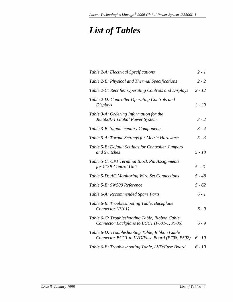
List of Tables
Table 2-A: Electrical Specifications 2 - 1
Table 2-B: Physical and Thermal Specifications 2 -
Table 2-C: Rectifier Operating Controls and Displays 2 -
Table 2-D: Controller Operating Controls and Displays 2 - 29
Table 3-A: Ordering Information for the J85500L-1 Global Power System 3 -
Table 3-B: Supplementary Components 3
Table 5-A: Torque Settings for Metric Hardware 5 -
Table 5-B: Default Settings for Controller Jumpers and Switches 5 - 18
Table 5-C: CP1 Terminal Block Pin Assignments for 113B Control Unit 5 - 21
Table 5-D: AC Monitoring Wire Set Connections 5 - 4
Table 5-E: SW500 Reference 5 - 6
Table 6-A: Recommended Spare Parts 6
Table 6-B: Troubleshooting Table, Backplane Connector (P101) 6 - 9
Table 6-C: Troubleshooting Table, Ribbon Cable Connector Backplane to BCC1 (P601-1, P706) 6
Table 6-D: Troubleshooting Table, Ribbon Cable Connector BCC1 to LVD/Fuse Board (P708, P502) 6 -
Table 6-E: Troubleshooting Table, LVD/Fuse Board 6 -
Issue 5 January 1998 List of Tables - 1
Lucent Technologies Lineage® 2000 Global Power System J85500L-1
he
inet
e,
net lant
fy
in
I) 00 ble
h
ac ls,
1 Introduction
General Information
This product manual (Select Code 167-790-047) describes tLineage® 2000 J85500L-1 Global Power System (GPS). Thisbattery plant operates from a nominal 208/240-volt ac, 50/60-hertz source. It offers a 600-ampere capacity per cabwith a nominal -48-volt output.
The J85500L-1 GPS is designed as a compact and complettotally integrated energy system package. It contains ac distribution, rectifiers, a controller, and dc fuse distribution, which can all be configured in one standard equipment cabior expanded into a supplementary distribution cabinet. The phas a modular front-access design for ease of installation, growth, and maintenance. This modular design architectureallows the system to grow in capacity and functionality to satisa broad range of applications around the world.
The J85500L-1 Global Power System was designed for usethe international telecommunications market. The design complies with European Technical Standards Institute (ETSstandards. The cabinet is 2200 mm high with a footprint of 6mm wide by 600 mm deep. Metric hardware is used to assemeach system component.
The basic system consists of charge/discharge bus bars witoptional low voltage battery disconnect/reconnect; an ECS controller; two rectifier shelf assemblies, each capable of connecting three -48-volt, 50-ampere switchmode rectifiers;distribution; and space for installing dc distribution fuse panea battery fuse disconnect panel, or two additional rectifier shelves.
Issue 5 January 1998 Introduction 1 - 1

Lucent Technologies Lineage® 2000 Global Power System J85500L-1
ere
ses.
gger.
d
in s the
and
s.
s ical
n via
ed
ld ur
The supplemental cabinet provides space for additional dc distribution panels, a battery fuse disconnect panel, and offline-equalize capabilities.
Plant output current is increased by adding -48-volt, 50-amprectifiers to the rectifier shelf assemblies. DC distribution is increased by adding fuse panels equipped with DIN fuse baTwo optional circuit packs are available, one to add microprocessor-based features and another to add a datalo
The J85500L-1 GPS is compatible with virtually all flooded anvalve-regulated batteries that float within the range of 48 through 58 volts. In addition, the plant is capable of operatingthe batteryless mode, making it suitable for those applicationwhere battery backup is not necessary or is achieved throughuse of an uninterrupted power supply (UPS).
This manual includes a general product description, basic features and options, ordering information, and engineering installation information. The main emphasis will be to familiarize the user with each major component in the systemand provide step-by-step installation and start-up procedure
Technical Support
Technical support for Lucent Technologies equipment is available to customers around the world.
USA, Canada,Puerto Rico, and
the US VirginIslands
On a post-sale basis, during the Product Warranty period, our Technical Support telephone number 1-800-CAL RTAC (1-800-225-7822) provides coverage during normal busineshours. Product Specialists are available to answer your technquestions and assist in troubleshooting problems. For out-of-hours EMERGENCIES, the 800 number will put you itouch with a Regional Technical Assistance Center Engineerour 24 hour a day, 7 day per week Help Desk.
When Technical Support is required in the Post-Warranty Period, the service may be billable unless you hold an extendwarranty or contractual agreement.
Central andSouth America
If you need product technical support, contact your local FieSupport/Regional Technical Assistance Center or contact yo
1 - 2 Introduction Issue 5 January 1998

Lucent Technologies Lineage® 2000 Global Power System J85500L-1
ific
ld ur ific
ld ur ific
t is
s
on.
on.
on.
on,
als,
sales representative who will be happy to discuss your specneeds.
Europe, MiddleEast, and Africa
If you need product technical support, contact your local FieSupport/Regional Technical Assistance Center or contact yosales representative who will be happy to discuss your specneeds.
Asia PacificRegion
If you need product technical support, contact your local FieSupport/Regional Technical Assistance Center or contact yosales representative who will be happy to discuss your specneeds.
Product Repair and Return
Repair and return service for Lucent Technologies equipmenavailable to customers around the world.
USA, Canada,Puerto Rico, and
the US VirginIslands
For information on returning of products for repair, customermay call 1-800-255-1402 for assistance.
Central andSouth America
If you need to return a product for repair, your sales representative will be happy to discuss your individual situati
Europe, MiddleEast, and Africa
If you need to return a product for repair, your sales representative will be happy to discuss your individual situati
Asia PacificRegion
If you need to return a product for repair, your sales representative will be happy to discuss your individual situati
Customer Service
For customer service, any other product or service informatior for additional copies of this manual or other Lucent Technologies documents, call 1-800-THE-1PWR (1-800-843-1797). Specify the select code number for manuor drawing number for drawings. Contact your regional customer service organization or sales representative for information regarding spare parts.
Issue 5 January 1998 Introduction 1 - 3
Lucent Technologies Lineage® 2000 Global Power System J85500L-1
2 Product Description
Specifications
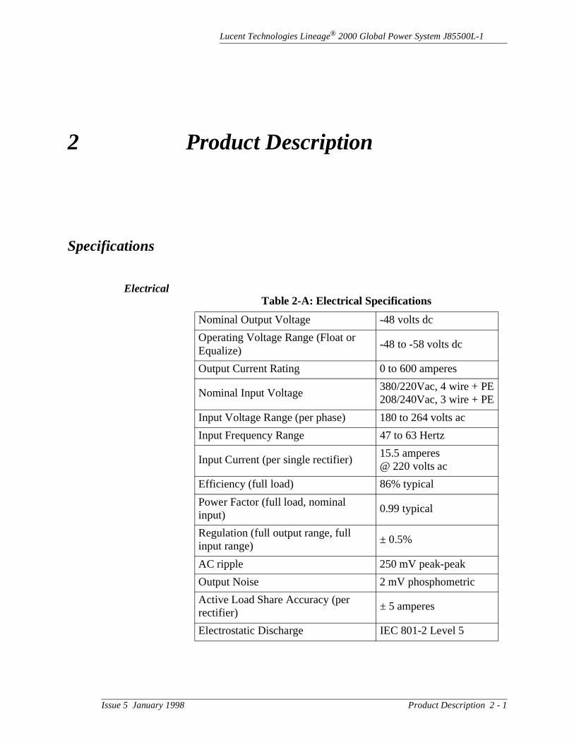
ElectricalTable 2-A: Electrical Specifications
Nominal Output Voltage -48 volts dc
Operating Voltage Range (Float or Equalize)
-48 to -58 volts dc
Output Current Rating 0 to 600 amperes
Nominal Input Voltage380/220Vac, 4 wire + PE208/240Vac, 3 wire + PE
Input Voltage Range (per phase) 180 to 264 volts ac
Input Frequency Range 47 to 63 Hertz
Input Current (per single rectifier)15.5 amperes @ 220 volts ac
Efficiency (full load) 86% typical
Power Factor (full load, nominal input)
0.99 typical
Regulation (full output range, full input range)
± 0.5%
AC ripple 250 mV peak-peak
Output Noise 2 mV phosphometric
Active Load Share Accuracy (per rectifier)
± 5 amperes
Electrostatic Discharge IEC 801-2 Level 5
Issue 5 January 1998 Product Description 2 - 1
Lucent Technologies Lineage® 2000 Global Power System J85500L-1
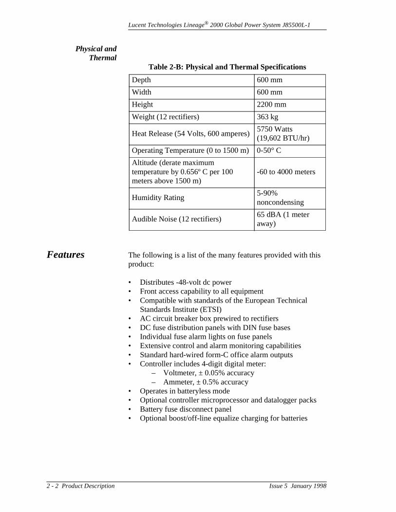
Physical andThermal
Features The following is a list of the many features provided with thisproduct:
• Distributes -48-volt dc power• Front access capability to all equipment• Compatible with standards of the European Technical
Standards Institute (ETSI)• AC circuit breaker box prewired to rectifiers• DC fuse distribution panels with DIN fuse bases• Individual fuse alarm lights on fuse panels• Extensive control and alarm monitoring capabilities• Standard hard-wired form-C office alarm outputs• Controller includes 4-digit digital meter:
– Voltmeter, ± 0.05% accuracy– Ammeter, ± 0.5% accuracy
• Operates in batteryless mode• Optional controller microprocessor and datalogger packs• Battery fuse disconnect panel• Optional boost/off-line equalize charging for batteries
Table 2-B: Physical and Thermal Specifications
Depth 600 mm
Width 600 mm
Height 2200 mm
Weight (12 rectifiers) 363 kg
Heat Release (54 Volts, 600 amperes)5750 Watts (19,602 BTU/hr)
Operating Temperature (0 to 1500 m) 0-50° C
Altitude (derate maximum temperature by 0.656º C per 100 meters above 1500 m)
-60 to 4000 meters
Humidity Rating5-90% noncondensing
Audible Noise (12 rectifiers)65 dBA (1 meter away)
2 - 2 Product Description Issue 5 January 1998
Lucent Technologies Lineage® 2000 Global Power System J85500L-1
it rm rs
ry
In ight
ws:
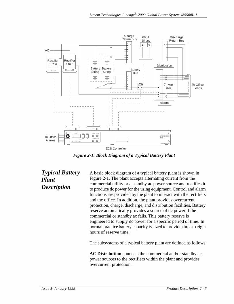
Typical Battery Plant Description
A basic block diagram of a typical battery plant is shown in Figure 2-1. The plant accepts alternating current from the commercial utility or a standby ac power source and rectifiesto produce dc power for the using equipment. Control and alafunctions are provided by the plant to interact with the rectifieand the office. In addition, the plant provides overcurrent protection, charge, discharge, and distribution facilities. Battereserve automatically provides a source of dc power if the commercial or standby ac fails. This battery reserve is engineered to supply dc power for a specific period of time. normal practice battery capacity is sized to provide three to ehours of reserve time.
The subsystems of a typical battery plant are defined as follo
AC Distribution connects the commercial and/or standby acpower sources to the rectifiers within the plant and providesovercurrent protection.
Figure 2-1: Block Diagram of a Typical Battery Plant
AC
Rectifier1 to 3
Rectifier4 to 6
BatteryString
BatteryString
BatteryBus
LVD ChargeBus
Alarms
FOR ESD WRIST STRAP
Distribution
DischargeReturn Bus
ChargeReturn Bus
600AShunt
OUTPUT VOLTS FLOAT
EOAMPS
NORMV
BD MJF
RFA
SWI
LINEAGE 2000
ECSµP
ACF
MNF
EO
Lucent Technologies
To OfficeLoads
To OfficeAlarms
ECS Controller
Issue 5 January 1998 Product Description 2 - 3

Lucent Technologies Lineage® 2000 Global Power System J85500L-1
vel sing
, ant.
r
the
t, , as he
.
tes ch
,
ery
e top
Rectifiers convert an ac source voltage into the dc voltage lerequired to charge and float the batteries and to power the uequipment.
Controller provides the local and remote control, monitoringand diagnostic functions required to administer the battery pl
Batteries provide energy storage for an uninterrupted powerfeed to the using equipment during loss of ac input or rectifiefailure.
DC Distribution provides overcurrent protection, connectionpoints for the using equipment, and bus bars to interconnectrectifiers, batteries, plant shunt and dc distribution.
Global Power System Description
The Global Power System Model J85500L-1 rectifier cabineshown in Figure 2-2, provides power for the using equipmentwell as float and recharge capability for the battery reserve. Tplant operates from a nominal 208/240Vac, 50/60Hz sourceNominal dc output is 48 volts with a 600-ampere total systemcapacity. The Global Power System’s modular design facilitainstallation and growth by using a basic building block approato solving the power needs of telecommunication customersaround the world.
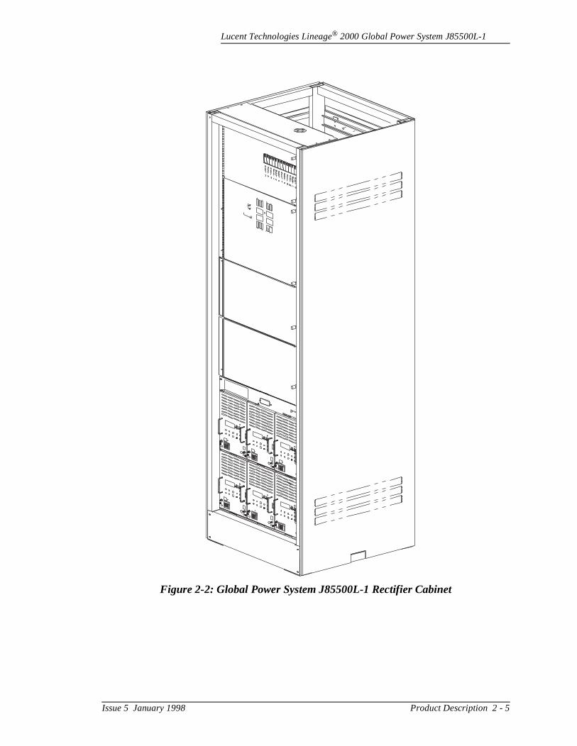
Rectifier Cabinet The rectifier cabinet accommodates up to twelve Lineage® 2000 SR series 48-volt, 50-ampere rectifiers, a Lineage® 2000 ECS controller, dc fuse distribution panels, ac circuit breaker boxbattery fuse disconnect panel, and a low voltage disconnect/reconnect feature. The ac circuit breaker box is located at the top of the cabinet, followed by space for threecustomer selected modules, which might include either additional rectifier shelves, dc distribution panels, or the battfuse disconnect panel. The ECS controller and two rectifier shelves are located in the bottom portion of the cabinet. Connections to the charge/discharge bus bars are made at thof the cabinet behind the ac circuit breaker box.
2 - 4 Product Description Issue 5 January 1998
Lucent Technologies Lineage® 2000 Global Power System J85500L-1
Figure 2-2: Global Power System J85500L-1 Rectifier Cabinet
Issue 5 January 1998 Product Description 2 - 5
Lucent Technologies Lineage® 2000 Global Power System J85500L-1
, ine l, lize
e
SupplementalCabinet
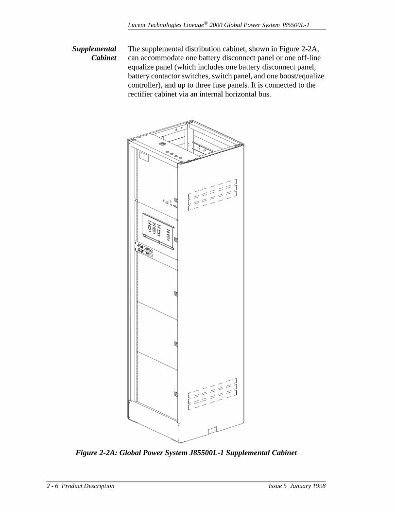
The supplemental distribution cabinet, shown in Figure 2-2Acan accommodate one battery disconnect panel or one off-lequalize panel (which includes one battery disconnect panebattery contactor switches, switch panel, and one boost/equacontroller), and up to three fuse panels. It is connected to threctifier cabinet via an internal horizontal bus.
Figure 2-2A: Global Power System J85500L-1 Supplemental Cabinet
2 - 6 Product Description Issue 5 January 1998
Lucent Technologies Lineage® 2000 Global Power System J85500L-1
r tes
the e
re
ent s the
ded
Global Power System Modules
The following paragraphs provide descriptions of the GlobalPower System modules.
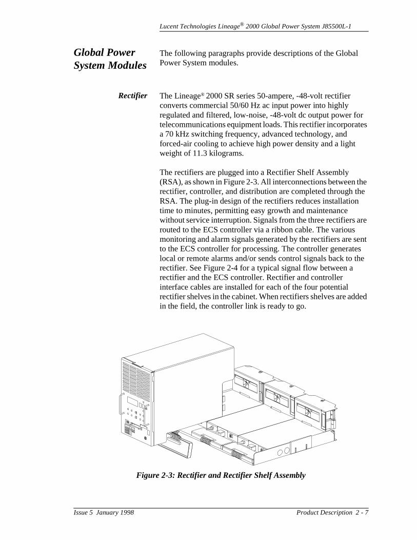
Rectifier The Lineage® 2000 SR series 50-ampere, -48-volt rectifier converts commercial 50/60 Hz ac input power into highly regulated and filtered, low-noise, -48-volt dc output power fotelecommunications equipment loads. This rectifier incorporaa 70 kHz switching frequency, advanced technology, and forced-air cooling to achieve high power density and a light weight of 11.3 kilograms.
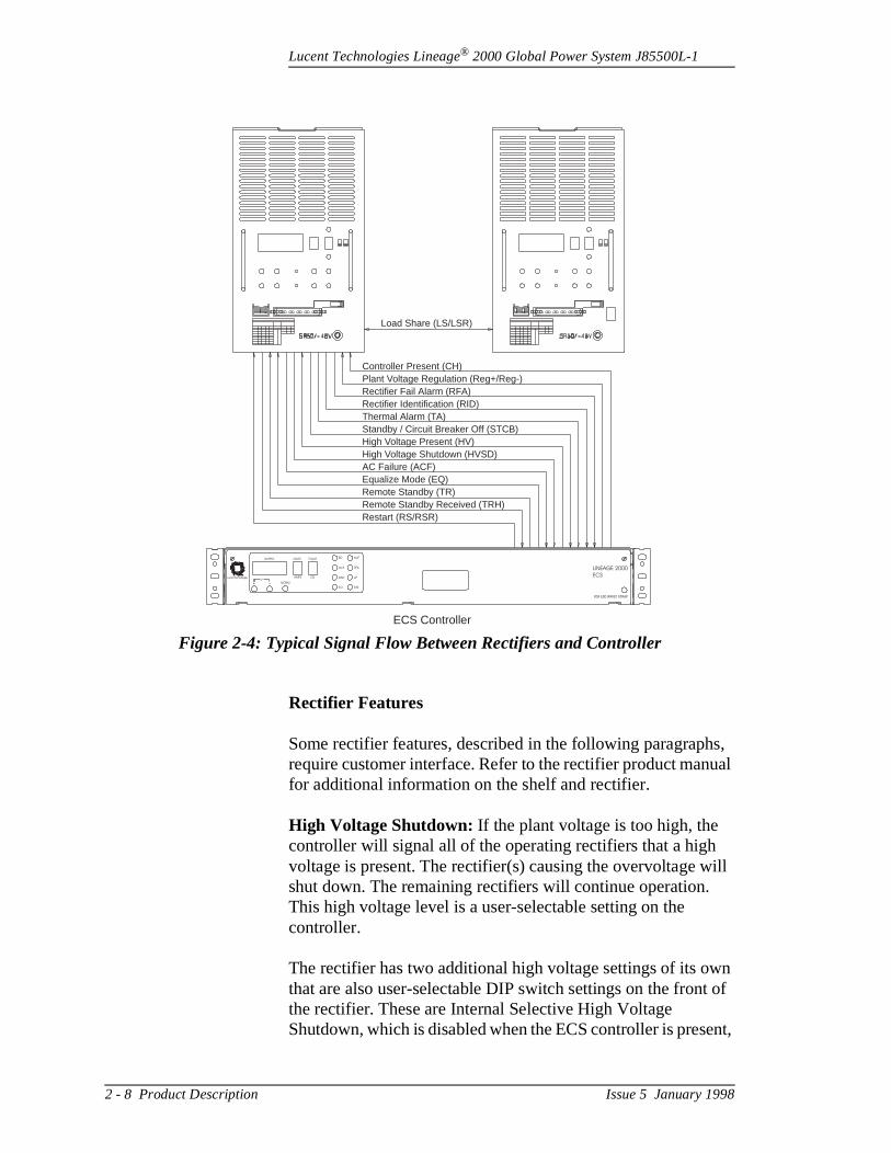
The rectifiers are plugged into a Rectifier Shelf Assembly (RSA), as shown in Figure 2-3. All interconnections between rectifier, controller, and distribution are completed through thRSA. The plug-in design of the rectifiers reduces installationtime to minutes, permitting easy growth and maintenance without service interruption. Signals from the three rectifiers arouted to the ECS controller via a ribbon cable. The various monitoring and alarm signals generated by the rectifiers are sto the ECS controller for processing. The controller generatelocal or remote alarms and/or sends control signals back to rectifier. See Figure 2-4 for a typical signal flow between a rectifier and the ECS controller. Rectifier and controller interface cables are installed for each of the four potential rectifier shelves in the cabinet. When rectifiers shelves are adin the field, the controller link is ready to go.
Figure 2-3: Rectifier and Rectifier Shelf Assembly
Issue 5 January 1998 Product Description 2 - 7
Lucent Technologies Lineage® 2000 Global Power System J85500L-1
s, ual
ill
n t of
ent,
Rectifier Features
Some rectifier features, described in the following paragraphrequire customer interface. Refer to the rectifier product manfor additional information on the shelf and rectifier.
High Voltage Shutdown: If the plant voltage is too high, the controller will signal all of the operating rectifiers that a high voltage is present. The rectifier(s) causing the overvoltage wshut down. The remaining rectifiers will continue operation. This high voltage level is a user-selectable setting on the controller.
The rectifier has two additional high voltage settings of its owthat are also user-selectable DIP switch settings on the fronthe rectifier. These are Internal Selective High Voltage Shutdown, which is disabled when the ECS controller is pres
Figure 2-4: Typical Signal Flow Between Rectifiers and Controller
Controller Present (CH)Plant Voltage Regulation (Reg+/Reg-)Rectifier Fail Alarm (RFA)Rectifier Identification (RID)Thermal Alarm (TA)Standby / Circuit Breaker Off (STCB)High Voltage Present (HV)High Voltage Shutdown (HVSD)AC Failure (ACF)Equalize Mode (EQ)Remote Standby (TR)Remote Standby Received (TRH)Restart (RS/RSR)
Load Share (LS/LSR)
FOR ESD WRIST STRAP
OUTPUT VOLTS FLOAT
EOAMPS
NORMV
BD MJF
RFA
SWI
LINEAGE 2000
ECSµP
ACF
MNF
EO
Lucent Technologies
ECS Controller
2 - 8 Product Description Issue 5 January 1998
Lucent Technologies Lineage® 2000 Global Power System J85500L-1
cy
a e
r.
e
e
ad fier ture of is
.)
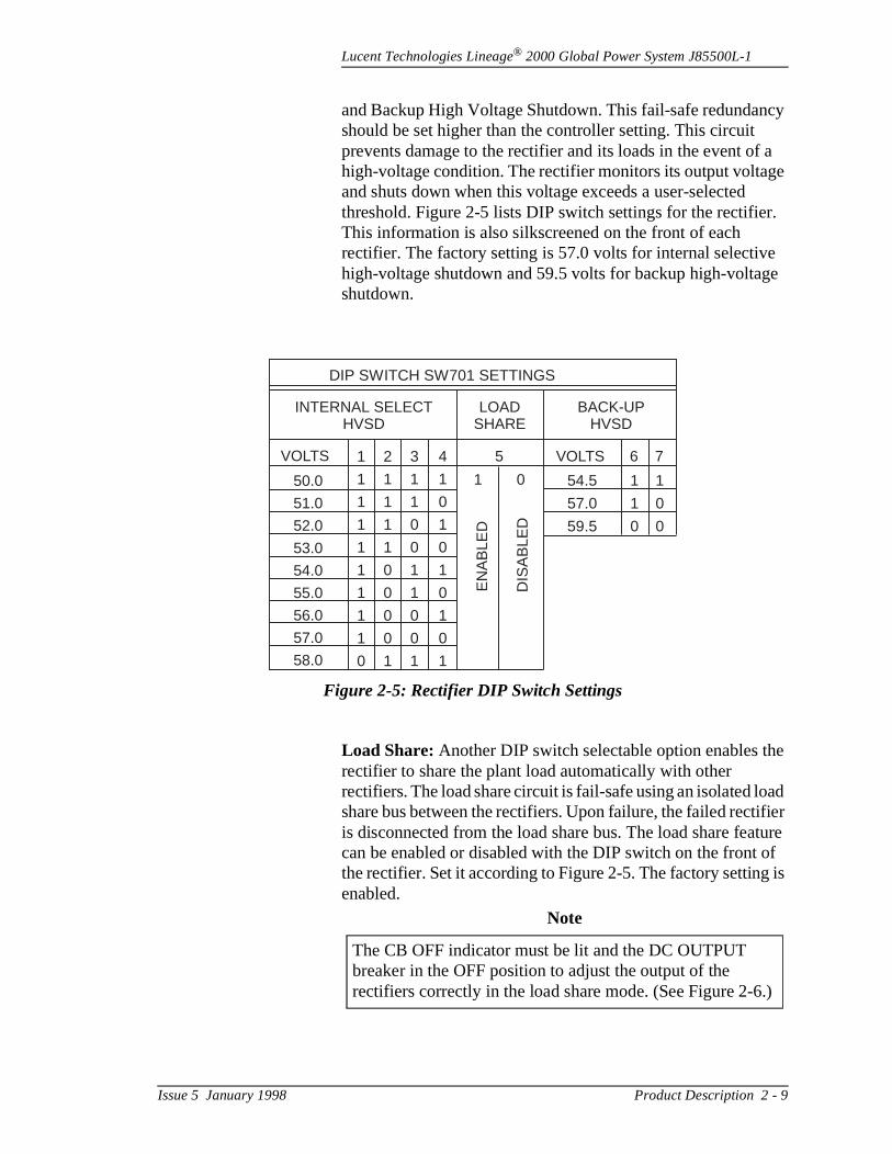
and Backup High Voltage Shutdown. This fail-safe redundanshould be set higher than the controller setting. This circuit prevents damage to the rectifier and its loads in the event ofhigh-voltage condition. The rectifier monitors its output voltagand shuts down when this voltage exceeds a user-selected threshold. Figure 2-5 lists DIP switch settings for the rectifieThis information is also silkscreened on the front of each rectifier. The factory setting is 57.0 volts for internal selectivehigh-voltage shutdown and 59.5 volts for backup high-voltagshutdown.
Load Share: Another DIP switch selectable option enables threctifier to share the plant load automatically with other rectifiers. The load share circuit is fail-safe using an isolated loshare bus between the rectifiers. Upon failure, the failed rectiis disconnected from the load share bus. The load share feacan be enabled or disabled with the DIP switch on the front the rectifier. Set it according to Figure 2-5. The factory settingenabled.
Figure 2-5: Rectifier DIP Switch Settings
DIP SWITCH SW701 SETTINGS
INTERNAL SELECTHVSD
BACK-UPHVSD
LOADSHARE
VOLTS VOLTS 6 75
50.0
51.0
52.0
53.0
54.0
55.0
56.0
57.0
58.0
1
1
1
1
1
1
1
1
1
0
2
1
1
1
1
0
0
0
0
1
3
1
1
0
0
1
1
0
0
1
4
1
0
1
0
1
0
1
0
1
54.5
57.0
59.5
1 1
1 0
0 0
1 0E
NA
BLE
D
DIS
AB
LED
Note
The CB OFF indicator must be lit and the DC OUTPUT breaker in the OFF position to adjust the output of the rectifiers correctly in the load share mode. (See Figure 2-6
Issue 5 January 1998 Product Description 2 - 9

Lucent Technologies Lineage® 2000 Global Power System J85500L-1
, . A
t s
nal
ly
e he
s
oint. fore n e
Equalize: The rectifier, in conjunction with the ECS controllercan charge batteries at higher voltages than the float voltageseparate potentiometer allows the equalize voltage to be seindependently of the float voltage. A front-panel LED indicatewhen the rectifier is in equalize mode.
Rectifier Test: A front panel switch is provided for automatically raising or lowering the output voltage of the rectifiers a small amount to test operation.
Lamp Test: This circuit allows the front panel display and LEDs to be tested. When the unit is in STBY and the NL/FL switch is pressed in either direction, all front panel LEDs andmeter segments will activate.
RFA (Rectifier Failure Alarm) Indicator: An RFA alarm provides both a local and visual indication of failure and a sigto the controller. An RFA is generated by the following:
– high voltage shutdown– thermal alarm– rectifier fuse alarm or circuit breaker overcurrent
operation
AC Fail Alarm: An ac input voltage of less than approximate170 Vrms causes an alarm to be issued to the controller.
Transfer (TR): The rectifier may be placed in the standby modby an externally generated signal. The rectifier will remain in tstandby mode until the removal of that signal.
Thermal Alarm (TA): The rectifier is fan cooled to increase itreliability. High temperatures caused by fan failure or other conditions cause a thermal alarm to be issued.
DC Output Breaker: A circuit breaker is provided to protect the rectifier from malfunction and overcurrent. It may also beused to disconnect the rectifier from the battery.
Test Jacks: Two sets of test jacks are provided. One set measures the plant voltage at the remote regulation sense pThe other set measures the voltage internal to the rectifier bethe dc output circuit breaker. When the circuit breaker is opeand the rectifier is on but disconnected from the local bus, threctifier output voltage can be adjusted without affecting theplant voltage.
2 - 10 Product Description Issue 5 January 1998
Lucent Technologies Lineage® 2000 Global Power System J85500L-1
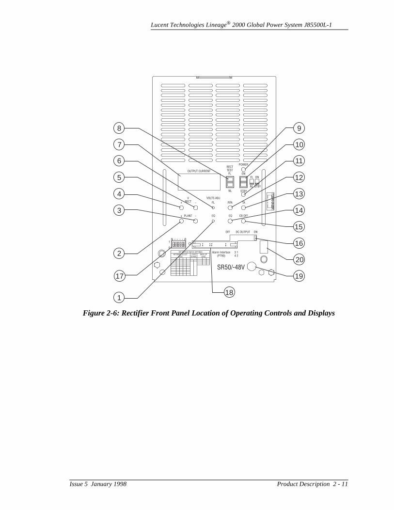
Figure 2-6: Rectifier Front Panel Location of Operating Controls and Displays
OUTPUT CURRENT
RECTTEST
FL
POWER
ONFL ON
STBY
STBY
NL
NL
VOLTS ADJ
FL RFA TA
CB OFF
OFF DC OUTPUT ON
Alarm Interface(P790)
1
0
DIP SWITCH SW701 SETTINGS
INTERNAL SELECTHVSD
BACK UPHVSD
LOADSHARE
3 14 2
SR50/-48V
EQEQPLANT
VRECT
98
107
116
125
134
143
2
1
15
16
20
1917
18
Issue 5 January 1998 Product Description 2 - 11
Lucent Technologies Lineage® 2000 Global Power System J85500L-1
wn e
f
8
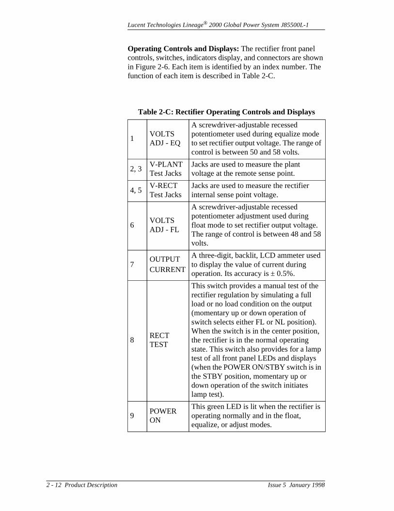
Operating Controls and Displays: The rectifier front panel controls, switches, indicators display, and connectors are shoin Figure 2-6. Each item is identified by an index number. Thfunction of each item is described in Table 2-C.
Table 2-C: Rectifier Operating Controls and Displays
1VOLTS ADJ - EQ
A screwdriver-adjustable recessed potentiometer used during equalize modeto set rectifier output voltage. The range ocontrol is between 50 and 58 volts.
2, 3V-PLANT Test Jacks
Jacks are used to measure the plant voltage at the remote sense point.
4, 5V-RECT Test Jacks
Jacks are used to measure the rectifier internal sense point voltage.
6VOLTS ADJ - FL
A screwdriver-adjustable recessed potentiometer adjustment used during float mode to set rectifier output voltage. The range of control is between 48 and 5volts.
7OUTPUTCURRENT
A three-digit, backlit, LCD ammeter usedto display the value of current during operation. Its accuracy is ± 0.5%.
8RECT TEST
This switch provides a manual test of therectifier regulation by simulating a full load or no load condition on the output (momentary up or down operation of switch selects either FL or NL position). When the switch is in the center position,the rectifier is in the normal operating state. This switch also provides for a lamptest of all front panel LEDs and displays (when the POWER ON/STBY switch is in the STBY position, momentary up or down operation of the switch initiates lamp test).
9POWER ON
This green LED is lit when the rectifier is operating normally and in the float, equalize, or adjust modes.
2 - 12 Product Description Issue 5 January 1998
Lucent Technologies Lineage® 2000 Global Power System J85500L-1
r
s
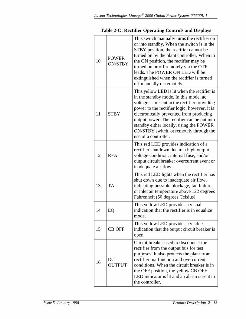
10POWER ON/STBY
This switch manually turns the rectifier onor into standby. When the switch is in theSTBY position, the rectifier cannot be turned on by the plant controller. When inthe ON position, the rectifier may be turned on or off remotely via the OTR leads. The POWER ON LED will be extinguished when the rectifier is turned off manually or remotely.
11 STBY
This yellow LED is lit when the rectifier is in the standby mode. In this mode, ac voltage is present in the rectifier providingpower to the rectifier logic; however, it is electronically prevented from producing output power. The rectifier can be put intostandby either locally, using the POWERON/STBY switch, or remotely through theuse of a controller.
12 RFA
This red LED provides indication of a rectifier shutdown due to a high output voltage condition, internal fuse, and/or output circuit breaker overcurrent event oinadequate air flow.
13 TA
This red LED lights when the rectifier hasshut down due to inadequate air flow, indicating possible blockage, fan failure, or inlet air temperature above 122 degreeFahrenheit (50 degrees Celsius).
14 EQThis yellow LED provides a visual indication that the rectifier is in equalize mode.
15 CB OFFThis yellow LED provides a visible indication that the output circuit breaker isopen.
16DC OUTPUT
Circuit breaker used to disconnect the rectifier from the output bus for test purposes. It also protects the plant from rectifier malfunction and overcurrent conditions. When the circuit breaker is in the OFF position, the yellow CB OFF LED indicator is lit and an alarm is sent tothe controller.
Table 2-C: Rectifier Operating Controls and Displays
Issue 5 January 1998 Product Description 2 - 13
Lucent Technologies Lineage® 2000 Global Power System J85500L-1
L-1
ly
r a
d. as
h all
the
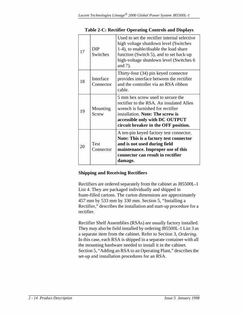
Shipping and Receiving Rectifiers
Rectifiers are ordered separately from the cabinet as J85500List 4. They are packaged individually and shipped in foam-filled cartons. The carton dimensions are approximate457 mm by 533 mm by 330 mm. Section 5, “Installing a Rectifier,” describes the installation and start-up procedure forectifier.
Rectifier Shelf Assemblies (RSAs) are usually factory installeThey may also be field installed by ordering J85500L-1 List 3a separate item from the cabinet. Refer to Section 3, Ordering. In this case, each RSA is shipped in a separate container witthe mounting hardware needed to install it in the cabinet. Section 5, “Adding an RSA to an Operating Plant,” describes set-up and installation procedures for an RSA.
17DIP Switches
Used to set the rectifier internal selective high voltage shutdown level (Switches 1-4), to enable/disable the load share function (Switch 5), and to set back-up high-voltage shutdown level (Switches 6 and 7).
18 Interface Connector
Thirty-four (34) pin keyed connector provides interface between the rectifier and the controller via an RSA ribbon cable.
19 Mounting Screw
5 mm hex screw used to secure the rectifier to the RSA. An insulated Allen wrench is furnished for rectifier installation. Note: The screw is accessible only with DC OUTPUT circuit breaker in the OFF position.
20Test Connector
A ten-pin keyed factory test connector. Note: This is a factory test connector and is not used during field maintenance. Improper use of this connector can result in rectifier damage.
Table 2-C: Rectifier Operating Controls and Displays
2 - 14 Product Description Issue 5 January 1998
Lucent Technologies Lineage® 2000 Global Power System J85500L-1
sic . It tus
log or he
ol r
re .
ith d dc l.
ller
e
d t
t
Controller Basic Configuration and Options
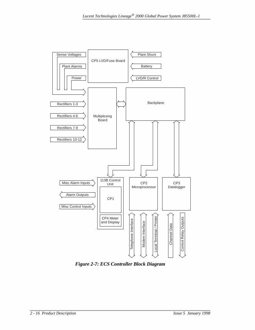
The ECS controller performs the centralized monitoring, control, and reporting functions for the battery plant. The baECS controller can monitor and control up to twelve rectifiersalso provides a single interface point for power alarm and stareporting.
A block diagram of the controller is shown in Figure 2-7. Thebasic configuration of the controller consists of the 113B anacontrol unit plugged into a backplane, with expansion slots fthe optional microprocessor and datalogger circuit modules. Trequired fuse board is located outside the controller.
The 113B Control Unit consists of two circuit packs, the contrboard (CP1) and the display board (CP4). Switch and jumpelocations on CP1 are shown in Figure 2-9.
The optional microprocessor board (CP2) is equipped with apowerful 16-bit microprocessor. It adds sophisticated firmwafeatures such as remote communications, alarm history, andstatistics. This board is available as List 5 or 7 on J85500L-1List 7 is the same as List 5, but with the addition of a voice response feature.
The optional datalogger board (CP3) is used in conjunction wthe microprocessor option to provide general purpose ac anvoltage, current and transducer monitoring, and relay controThis board is available as List 8 on J85500L-1.
The required fuse board (CP5) provides fusing for the controand rectifier sense leads, and also provides a low voltage detection circuit for monitoring the optional low voltage disconnect/reconnect contactor. The CP5 Fuse Board will bdiscussed in detail in a later paragraph.
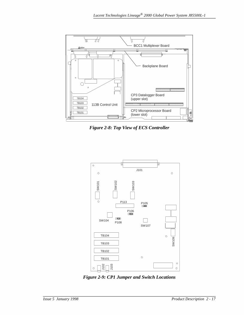
Figure 2-8 is a top view of the ECS controller. The chassis isequipped with a rectifier multiplexing circuit pack (BCC1) anthe standard analog control unit (113B Control Unit) pluggedinto a backplane, with expansion slots for two optional circuipacks.
For additional information on the optional microprocessor controller board (CP2), datalogger board (CP3), and voice response option, refer to the ECS Controller Options ProducManual, 167-790-109.
Issue 5 January 1998 Product Description 2 - 15
Lucent Technologies Lineage® 2000 Global Power System J85500L-1
Figure 2-7: ECS Controller Block Diagram
Sense Voltages
Plant Alarms
Power
Rectifiers 1-3
Rectifiers 4-6
Rectifiers 10-12
Rectifiers 7-9
CP5 LVD/Fuse Board
MultiplexingBoard
Backplane
Plant Shunt
Battery
LVD/R Control
Misc Alarm Inputs
Alarm Outputs
Misc Control Inputs
CP1
113B ControlUnit
CP4 Meterand Display
CP2Microprocessor
CP3Datalogger
Tele
phon
eIn
terf
ace
Mod
emIn
terf
ace
Loca
l Ter
min
al/ P
rinte
r
Cha
nnel
Dat
a
Con
trol
Rel
ayO
utpu
ts
2 - 16 Product Description Issue 5 January 1998
Lucent Technologies Lineage® 2000 Global Power System J85500L-1
Figure 2-8: Top View of ECS Controller
CP2 Microprocessor Board(lower slot)
CP3 Datalogger Board(upper slot)
113B Control Unit
Backplane Board
BCC1 Multiplexer Board
TB104
TB103
TB102
TB101
Figure 2-9: CP1 Jumper and Switch Locations
J101
P105P113
P106
P108
TB104
TB103
TB102
TB101
J102
J103
SW104
SW107
SW
109
SW
101
SW
102
SW
103
Issue 5 January 1998 Product Description 2 - 17
Lucent Technologies Lineage® 2000 Global Power System J85500L-1
og
ted ge.
n loss
o
r
ge eir
t of
f s O lly this d to
of s
Controller Functions
The controller equipped with the rectifier multiplexing circuit pack and the 113B Control Unit performs the traditional analcontrol functions described in the paragraphs that follow:
Operating Voltage: The controller is powered by the plant dcvoltage and may be used in 24V or 48V plants. It may be powered from either positive ground systems (e.g., -48V) ornegative ground systems (e.g., +24V). Movable jumpers locaon the backplane are positioned according to the plant voltaThese jumpers are factory set for 48 volts.
Batteryless Operation: The ECS controller is suitable for telecommunications power plants with or without batteries. Ibatteryless plants, the loss of ac power causes an immediateof dc power to the controller. When ac power is restored, theECS controller, in an unpowered state, allows the rectifiers tautomatically restart.
Rectifier Sense Leads: Separately fused sense leads run fromthe external fuse board (CP5) to the rectifiers via the rectifiemultiplexing circuit pack (BCC1). These leads are not interrupted when the 113B Control Unit is removed. The rectifiers use the sense leads to maintain the plant bus voltaindependent of any load-dependent voltage drop between thoutput terminals and the bus.
Office Alarm Contacts and Alarm Battery Supply: Alarm contacts are provided on the 113B Control Unit that may beconnected to the office alarm system by the installer. Each secontacts is a Form-C or transfer-type; i.e., a combination of normally open and normally closed contacts with one side oeach in common. The normally open contact is referred to a(other applications may call this the NO contact), the normaclosed contact is referred to as C (other applications may callthe NC contact), and the common or return contact is referreas R (other applications may call this the C contact). Each
Important
When the controller loses power, it also loses the ability todetect alarm conditions in the plant. To prevent the danger unreported alarms, all power major and power minor alarmare automatically issued when the controller is powered down.
2 - 18 Product Description Issue 5 January 1998

Lucent Technologies Lineage® 2000 Global Power System J85500L-1
of
e a
les
the
s ir of
are r a
le red to rm d is
an ary n the
Form-C set is isolated. An alarm set is provided for each typealarm condition, as follows:
– AC Failure (ACF)– Major Fuse Failure (MJF)– Minor Fuse Failure (MNF)– High Voltage (HV)– Battery on Discharge (low voltage) (BD)– Low Voltage Battery Disconnect (LV)
In addition, alarms that are classified as Major or Minor causgroup of general-purpose major or minor alarms, as follows:
– Power Major - Visible (PMJV)– Power Major - Audible (PMJA)– Power Major - External (PMJE)– Power Minor - Visible (PMNV)– Power Minor - Audible (PMNA)– Power Minor - External (PMNE)
The alarm state is the “normal” state; i.e., when an alarm condition exists, a closure exists between the “C” and “R” poand an open exists between the “O” and “R” poles.
Each set of contacts can be in the non-alarm state only whencontrol unit is powered and the corresponding alarm is not present. When an alarm occurs or when the control unit losepower, each closed pair of contacts opens and each open pacontacts closes. Terminal blocks TB102, TB103, and TB104 assigned to the various alarm outputs. Refer to Table 5-C folist of terminal block pin assignments.
Alarm Battery Supply (ABS) and a ground return are availabon one of the terminal blocks (TB101). These pins may be wiby the installer to one or more alarms on the terminal blocksdrive alarm lamps, buzzers, or remote relays in the office alasystem. ABS is the same voltage as the plant bus voltage anseparately fused on the external fuse board.
Adjustable Battery on Discharge Alarm: If rectifier output is insufficient to supply the load current for any reason (such asac power failure), the battery reserve will provide the necesscurrent. Such a battery discharge can be detected by a drop iplant bus voltage. Whenever the plant voltage drops below apreselected threshold, the controller issues a Battery on Discharge alarm (BD) and lights a red LED on the controller
Issue 5 January 1998 Product Description 2 - 19

Lucent Technologies Lineage® 2000 Global Power System J85500L-1
e nce hen ly.
or D
y . A ge
r by e e
oad,
sted e
.
us.
s. r
ller
to , so
s a rs be n a e,
front panel. This alarm threshold is typically set to indicate thonset of battery discharge to allow enough time for maintenapersonnel to respond before battery reserve is exhausted. Wa BD alarm occurs, service is not usually affected immediateHowever, since attention is required in a limited time, BD is considered a MAJOR alarm. Therefore, all three Power Majalarm groups are issued to the office alarm system when a Boccurs.
It should be noted here that a BD alarm does not necessarilindicate that rectifier output current has been lost or reducedBD alarm can be caused by misadjusted rectifier output voltaduring otherwise normal operation. It can also be caused bycurrent overload on normally functioning rectifiers.
The voltage threshold for the BD alarm is selected by the usesetting a group of DIP switches on the 113B Control Unit. Thsetpoint is typically at least 1 volt below the plant float voltagfor nominal 48-volt plant systems. This threshold avoids nuisance alarms due to component tolerances, variations in land other transient conditions.
The actual BD threshold settings that may be selected are lion a label on the controller. Figure 2-10 is a replication of thlabel. The range of available settings is based on the most common battery float voltage for 24-volt and 48-volt systems
Adjustable Selective High Voltage Shutdown: The controller is equipped to detect a high voltage condition on the plant bSuch a high voltage condition is typically caused by lightning-induced transients on the commercial ac power lineA rectifier failure might, however, cause an individual rectifieto increase its output voltage. To prevent high voltage from damaging the connected telecommunications load, the controwill shut down rectifiers that deliver high voltage power.
When the controller detects an increase in the plant voltageabove a preset threshold, it immediately issues an HV alarmthe external alarm system. HV is considered a MAJOR alarmall Power Major alarm groups are also issued.
When reporting the alarm, the controller simultaneously sendshutdown signal to all rectifiers. Since the outputs of all rectifieare paralleled in the plant, their output voltages are forced tothe same. Their output currents, however, may vary widely. Ihigh-voltage condition caused by an individual rectifier failur
2 - 20 Product Description Issue 5 January 1998
Lucent Technologies Lineage® 2000 Global Power System J85500L-1
er he ed
g
e
e
by .
oat set
int
ate
to the ge he
ld HV ng en
the failed rectifier will be supplying more current than any othrectifier. When the high voltage shutdown signal is sent by tcontroller, the rectifier supplying the most current (i.e., the failrectifier) will shut down, causing the plant voltage to drop to normal and the HV alarm to retire. All other rectifiers will remain on. If a high-voltage condition exists without an individual rectifier failure (e.g., because of an incorrect settinof the HV-threshold DIP switches or lightning-induced high voltage) the rectifier with the highest output current will shutdown, but the HV condition will remain. The rectifier with thehighest output current of those remaining on will shut down next, but again the HV condition will remain. This will continuuntil all rectifiers have shut down. Although it is a sequential shutdown of rectifiers, the timing is very fast and it will appear as if all rectifiers have shut down simultaneously. The detection of the high-voltage condition and the sending of thshutdown signal are functions of the controller, while the selection of the rectifier with the highest output current for shutdown is a function of the rectifiers.
The high voltage shutdown threshold voltage should be set the user to a prescribed margin above the plant float voltageThis margin is typically 1.5 volts for nominal 48-volt battery plants. Since voltage fluctuations are greater in batteryless plants, the shutdown margin is typically set at 3 volts above flin 48-volt batteryless plants. The actual threshold voltage is with a group of DIP switches on the 113B Control Unit. DIP switches provide a visual verification of the shutdown set poat all times.
For plants configured with the float/equalize feature, a separhigh voltage shutdown threshold is used when the plant is inequalize mode. A separate group of DIP switches are used select the HV shutdown threshold for equalize mode. When plant is switched from float to equalize, the equalize high voltashutdown threshold becomes effective immediately. When tplant is switched from equalize to float, the equalize high-voltage shutdown threshold remains effective for 2-4 minutes, after which the float high-voltage shutdown threshobecomes effective. This delay is necessary to avoid nuisancealarms and shutdowns that would occur if the float thresholdbecame effective while the battery voltage was slowly droppifrom the equalize voltage to the float voltage. This feature isbasically transparent in normal plant operation, but could bemisinterpreted as a failure in the HV detection circuit if not takinto account during acceptance testing or troubleshooting.
Issue 5 January 1998 Product Description 2 - 21
Lucent Technologies Lineage® 2000 Global Power System J85500L-1
f inal s
.
itch ed, t sor ins hen V he
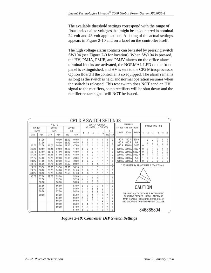
The available threshold settings correspond with the range ofloat and equalize voltages that might be encountered in nom24-volt and 48-volt applications. A listing of the actual settingappears in Figure 2-10 and on a label on the controller itself
The high voltage alarm contacts can be tested by pressing swSW104 (see Figure 2-9 for location). When SW104 is pressthe HV, PMJA, PMJE, and PMJV alarms on the office alarmterminal blocks are activated, the NORMAL LED on the fronpanel is extinguished, and HV is sent to the CP2 MicroprocesOption Board if the controller is so equipped. The alarm remaas long as the switch is held, and normal operation resumes wthe switch is released. This test switch does NOT send an Hsignal to the rectifiers, so no rectifiers will be shut down and trectifier restart signal will NOT be issued.
Figure 2-10: Controller DIP Switch Settings
CP1 DIP SWITCH SETTINGSSWITCH POSITION
(0 = OPEN, 1 = CLOSED)
THIS PRODUCT CONTAINS ELECTROSTATICSENSITIVE DEVICES. INSTALLATION AND
MAINTENANCE PERSONNEL SHALL USE ANESD GROUND STRAP TO PREVENT DAMAGE.
–1 –1
150 A300 A600 A
300 A600 A
1200 A
600 AN/A
2400
25mV 50mV 100mV
101
101
101
101
001
110
111
111
110
001
001
110
010
011
100
46.0046.5047.00
47.5048.0048.50
24.5025.0025.50
50.5051.0051.50
25.2525.7526.25
52.5053.0053.50
26.2526.7527.25
27.7528.2528.75
29.2529.7530.25
55.5056.0056.50
28.2528.7529.25
53.5054.0054.50
27.5028.0028.50
50.5051.0051.50
52.0052.5053.00
55.0055.5056.00
57.0057.5058.00
58.5059.0059.50
56.5057.0057.50
53.5054.0054.50
55.0055.5056.00
58.0058.5059.00
59.5060.00
56.5057.0057.50
60.00
30.75 29.75
54.0054.5055.00
26.7527.2527.75
52.0052.5053.00
26.0026.5027.00
49.0049.5050.00
23.0023.5024.00
49.0049.5050.00
51.0051.5052.00 24.7525.75
110
111
111
111
111
111
111
111
111
100
111
111
111
111
111
111
111
111
111
000
000
000
000
000
000
000
000
000
100
010
000
000
000
000
000
010
010
011
011
011
100
110
001
000
000
1000 A1300 A2000 A
2000 A2600 A4000 A
4000 A5200 A8000 A
3000 A4000 A
6000 A8000 A
N/AN/A
10
00
00
00
00
00
* ECS BATTERY PLANTS USE A 50mV Shunt
846885804
CAUTION
000
101
010
000
100
100
100
100
–2 –2–3 –3–4 –4–5 –5–6
–624V24V 24V 24V 48V48V 48V 48V
SW 103–SW 102–SW 101–
HV/EQ HV/FL BD
AMPERES
SW 109 – METER SHUNTSWITCH POSITION
2 - 22 Product Description Issue 5 January 1998

Lucent Technologies Lineage® 2000 Global Power System J85500L-1
s art ay the
res. d 9. . In re in e
fect ller onal t s the
tart
or nt e ill
es his o
d a on
or ee n
one he
Automatic Rectifier Restart: A high voltage shutdown from the controller is typically followed by an automatic restart signal. When the controller detects that one or more rectifierhave responded to its HV signal by shutting down, there is a3- to 5-second delay, after which the controller issues a restsignal to all rectifiers. Rectifiers that have shut down may or mnot respond to the restart signal, depending on the nature offailure.
The restart signal consists of two sets of clean contact closuOne set of closures is connected to rectifiers 1, 2, 3, 7, 8, anThe other set is connected to rectifiers 4, 5, 6, 10, 11, and 12this way, different types of rectifiers with restart circuits that aotherwise incompatible may be combined (in groups of six) one plant. Different rectifier types may not be mixed within ongroup of six rectifiers.
After the controller issues the restart closures, they stay in effor the next 4 to 6 minutes and then they reopen. The controdoes not issue a new restart signal in response to any additihigh voltage events in that 4- to 6-minute period. The timeouperiod is intended to prevent multiple shutdown/restart cycleduring heavy lightning storms, which would otherwise stress power equipment.
Rectifiers that have not shut down are not affected by the ressignal from the controller and continue to run normally. Rectifiers that have restarted in response to the signal will resume normal operation unless lightning activity continues unless they are actually faulty units. In either case, if the plavoltage goes high again during the 4- to 6-minute timeout, thshutdown signal (see previous section) will be reissued but wnot be followed by an automatic restart.
The 4- to 6-minute timer may be reset manually before it timout by pressing switch SW107 (see Figure 2-9 for location). Tmay be desirable during testing of the restart circuit. See alsSection 5, “Acceptance Testing.” The timer will also reset anrestart will be issued if the controller loses power for any reas(e.g., if controller fuses are removed).
The automatic restart function may be disabled by the user installer by moving a jumper strap on the basic controller. (SSection 5, “Hardware Setup,” for this procedure.) This functioshould be disabled for batteryless plants equipped with only rectifier. In such an application, the controller loses power if t
Issue 5 January 1998 Product Description 2 - 23

Lucent Technologies Lineage® 2000 Global Power System J85500L-1
the e e ier.
es
ncy in to rm
f a
r e,
t as an F
or or a y to ng
s
s. se he
rectifier is shut down and, in the process, issues a restart. Ifone rectifier shuts down again, the cycle will repeat, since thcontroller will again lose power. To prevent a possibly infinitcycle of shutdown and restart, the automatic restart functionshould be disabled for batteryless plants with only one rectif
Rectifier Fail Alarm: Whenever a rectifier fail signal is received by the controller from any rectifier, the controller issua rectifier fail alarm (RFA) to the office alarm system and a yellow LED lights on the controller front panel.
A loss of one or more rectifiers is not necessarily an emergeunless the plant voltage starts to drop and the batteries begdischarge. Rectifier Fail is, therefore, treated as a MINOR alaby the controller, which issues all three sets of Power Minoroffice alarms in addition to the separate RFA alarm. If loss orectifier output causes the plant voltage to drop significantly,BD alarm is issued, which is a MAJOR alarm condition.
If a failed rectifier is successfully restarted, either manually oautomatically, or if it disconnected from the controller interfacthe RFA LED will extinguish and the associated alarms will retire.
AC Fail Alarm: The AC Fail Alarm is intended to indicate thaac input power to at least one rectifier has disappeared or hdropped below a minimum voltage. This alarm is provided asisolated transfer contact for the office alarm systems. An ACalarm also lights a yellow LED on the front panel of the controller.
Since users may classify the loss of ac power as either a maja minor alarm condition, ACF does not automatically result inPower Major or Power Minor alarm. The user or installer mahardwire parallel the ACF alarm to the desired Power Alarmgive loss of ac the proper priority. See Section 5 for alarm wiridetails.
Major and Minor Fuse Alarms: The controller monitors all fuse and circuit breaker protection devices in the plant for operation. Each blown fuse or tripped circuit breaker is classified as either a MAJOR or MINOR alarm. MAJOR fuseor circuit breakers protect service-affecting circuits, basic controller circuits, and alarm circuits that report major alarmLoss of any other circuit protectors are treated as MINOR fualarms. Examples of MAJOR fuses include load fuses and t
2 - 24 Product Description Issue 5 January 1998

Lucent Technologies Lineage® 2000 Global Power System J85500L-1
n
nt
ted ice nor cks
uit r to s
al ry
g
r
Alarm Battery Supply (ABS) fuse. Rectifier regulation fuses, othe other hand, are MINOR fuses.
A red MJF LED on the controller front panel lights in the eveof a Major Fuse Alarm. Similarly, a yellow MNF LED lights following a Minor Fuse Alarm. Fuse alarms cause the associaPower Major and Power Minor alarms to be issued to the offalarm system. In addition, separate Major Fuse Alarm and MiFuse Alarm transfer contacts are provided to the office alarmsystem. See Section 5 for alarm designations on terminal bloTB102-TB104.
Open Battery String Protection and Alarm: In a plant equipped with battery string disconnects, the disconnect circbreakers on each battery string may be wired to the controlleindicate when they are open. The open breaker signal occurwhen a battery string breaker is tripped manually or electronically. The Open String alarm (OS) is passed as a separate alarm to CP2 (optional microprocessor controller board).
If the OS signal is wired directly to the controller alarm terminblocks, it will generate a Minor Fuse Alarm whenever a battestring is open. Alternatively, OS may be hardwired to the auxiliary major fuse alarm input on the external fuse board.
Front Panel Status Indicators: Light-emitting diodes (LEDs) are located on the controller front panel to indicate the alarmstatus of the battery plant. Yellow LEDs indicate the followinconditions, including (but not restricted to) Power MINOR alarms:
– Minor Fuse Alarm (MNF)– Rectifier Fail (RFA)– AC Fail (ACF)– Equalize On (EQ)– Microprocessor Alarm (See also ECS Controller
Options Product Manual, 167-790-109)– Datalogger Alarm (DLA) (See also ECS Controlle
Options Product Manual, 167-790-109)
Red LEDs indicate the following Power MAJOR alarms:
– Battery on Discharge (BD)– Major Fuse Alarm (MJF)
Issue 5 January 1998 Product Description 2 - 25

Lucent Technologies Lineage® 2000 Global Power System J85500L-1
the
e for
cts . A
is
a
ds er
nt. d by ale
.
r's nt eld l
ted ers be
d
When no alarms are present and the controller is powered, green NORM LED lights to indicate normal operation. The Equalize LED (EQ) may light when the NORM LED is on, sincequalize is not considered an alarm condition. See Section 5more information on the Equalize function.
Front Panel Meter: A four-digit, backlit liquid-crystal display is located on the front panel. A switch next to the display seleeither the plant voltage or the plant load current to be showncalibration potentiometer (R407) is provided inside the controller for fine adjustment of the plant voltmeter. (See Section 5, “Meter Calibration,” for additional details.) When thswitch is set in the AMPS position, the display indicates the plant load current in amperes. This current is measured withcalibrated shunt located in the dc distribution return bus.
The load current display has a total of four digits. For plant loaof 999A or less, such as the Global Power System, the jump(P401) on the CP4 display board is factory set to display a decimal point (xxx.x).
Selectable Ammeter Scale: The controller has a selectable ammeter scale for monitoring the plant shunt of the battery plaThe ammeter scale for a particular plant shunt size is selecteDIP switch SW109 on the 113B Control Unit. Refer to Figure2-9. The plant shunt in the Global Power System has a full scrating of 50 millivolts at the maximum plant current rating of 600 amperes. SW109 is set by the factory for this shunt size
Front Panel Test Jacks: Test points are provided on the frontpanel so that the plant voltage may be checked with the usemeter. However, the accuracy of the LCD voltmeter on the fropanel, at 0.05%, is better than that available with most hand-hmeters. The test points are current-limited against accidentashort-circuits by test probes.
Rectifier Sequence Control Interface: When the battery plant's ac power is backed up by an engine alternator of limicapacity, it is often necessary to control the number of rectifion-line during a commercial ac outage. To avoid stalling theengine during start up or overloading it at steady-state, it maynecessary to turn off rectifiers temporarily until the engine comes up to speed. This operation of turning rectifiers off anback on during engine start up is called Rectifier Sequence Control.
2 - 26 Product Description Issue 5 January 1998

Lucent Technologies Lineage® 2000 Global Power System J85500L-1
als
ther nce ith
See
her
th o n a
e
d
s s. n. is
he s the
The ECS controller may be connected to the four output signTR1, TR2, TR3, and TR4 provided by a Rectifier Sequence Controller, such as Lucent Technologies Model J87339A-1. These signals are used to turn off rectifiers or groups of rectifiers.
Sequence control is typically part of the ac engine system rathan part of the dc battery plant system. The Rectifier SequeController is often outside the battery plant and interfaces wthe rectifiers through the battery plant controller.
The controller equipped with CP2 is capable of Rectifier Sequence Control without an external sequence controller. (ECS Controller Options Product Manual, 167-790-109.)
The TR signal input to the controller may also be used for oton/off control of rectifiers by an external control device. (SeeECS Controller Options Product Manual, 167-790-109.)
Float/Equalize Control: The rectifiers are capable of battery equalize charging in addition to normal float charging. The equalize feature may be used to recharge flooded-type (i.e.,non-sealed) batteries after a discharge more quickly than wiconventional float charging. Some battery manufacturers alsrecommend equalize charging to equalize cell voltages withistring after a discharge.
The controller has several methods of controlling the equalizfunction in plants that are so equipped.
Hardware Disable: A movable jumper strap on the 113B Control Unit may be used to disable the equalize function anlock the plant in float mode. This is especially important for plants equipped with sealed-type or valve-regulated batterieand for plants powering equipment sensitive to high voltageBatteryless plants also have no need for the equalize functioThe controller is always shipped with equalize disabled by thjumper to prevent accidental misapplication of the equalize feature. See Section 5, “Hardware Setup,” for details.
Local Manual Control: A momentary toggle switch on the controller front panel may be used to switch the rectifiers in tplant from float mode to equalize mode and back again. Thicontrol is disabled when equalize is hardware disabled with jumper described above.
Issue 5 January 1998 Product Description 2 - 27
Lucent Technologies Lineage® 2000 Global Power System J85500L-1
ze
re oller
ple, an
L
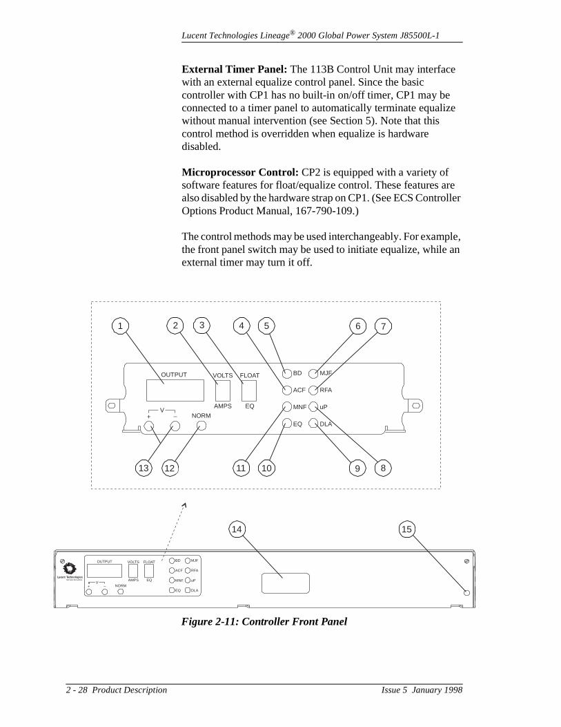
External Timer Panel: The 113B Control Unit may interface with an external equalize control panel. Since the basic controller with CP1 has no built-in on/off timer, CP1 may be connected to a timer panel to automatically terminate equaliwithout manual intervention (see Section 5). Note that this control method is overridden when equalize is hardware disabled.
Microprocessor Control: CP2 is equipped with a variety of software features for float/equalize control. These features aalso disabled by the hardware strap on CP1. (See ECS ContrOptions Product Manual, 167-790-109.)
The control methods may be used interchangeably. For examthe front panel switch may be used to initiate equalize, whileexternal timer may turn it off.
Figure 2-11: Controller Front Panel
1514
OUTPUT VOLTS
AMPS
FLOAT
EQ
BD
ACF
MNF
EQ
MJF
RFA
uP
DLANORM
V+ _
OUTPUT VOLTS
AMPS
FLOAT
EQ
BD
ACF
MNF
EQ
MJF
RFA
uP
DLANORM
V+ _
13 12 11 10 89
6 74 52 31
ucent TechnologiesBell Labs Innovations
2 - 28 Product Description Issue 5 January 1998
Lucent Technologies Lineage® 2000 Global Power System J85500L-1
d in
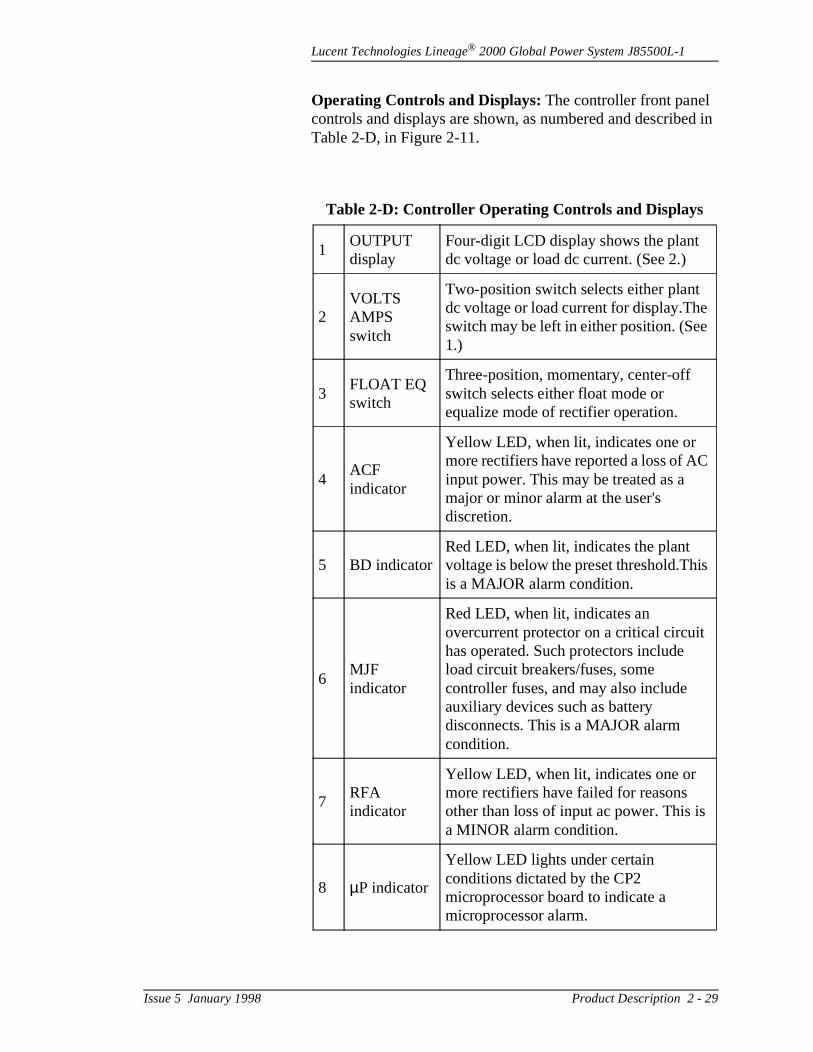
Operating Controls and Displays: The controller front panel controls and displays are shown, as numbered and describeTable 2-D, in Figure 2-11.
Table 2-D: Controller Operating Controls and Displays
1OUTPUT display
Four-digit LCD display shows the plant dc voltage or load dc current. (See 2.)
2VOLTS AMPS switch
Two-position switch selects either plant dc voltage or load current for display.Theswitch may be left in either position. (See1.)
3 FLOAT EQ switch
Three-position, momentary, center-off switch selects either float mode or equalize mode of rectifier operation.
4ACF indicator
Yellow LED, when lit, indicates one or more rectifiers have reported a loss of ACinput power. This may be treated as a major or minor alarm at the user's discretion.
5 BD indicatorRed LED, when lit, indicates the plant voltage is below the preset threshold.Thisis a MAJOR alarm condition.
6MJF indicator
Red LED, when lit, indicates an overcurrent protector on a critical circuit has operated. Such protectors include load circuit breakers/fuses, some controller fuses, and may also include auxiliary devices such as battery disconnects. This is a MAJOR alarm condition.
7RFA indicator
Yellow LED, when lit, indicates one or more rectifiers have failed for reasons other than loss of input ac power. This isa MINOR alarm condition.
8 µP indicator
Yellow LED lights under certain conditions dictated by the CP2 microprocessor board to indicate a microprocessor alarm.
Issue 5 January 1998 Product Description 2 - 29
Lucent Technologies Lineage® 2000 Global Power System J85500L-1
se er nd lant a
wer for ,
t
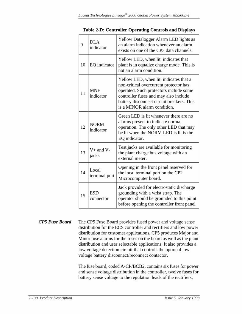
CP5 Fuse Board The CP5 Fuse Board provides fused power and voltage sendistribution for the ECS controller and rectifiers and low powdistribution for customer applications. CP5 produces Major aMinor fuse alarms for the fuses on the board as well as the pdistribution and user selectable applications. It also provideslow voltage detection circuit that controls the optional low voltage battery disconnect/reconnect contactor.
The fuse board, coded A-CP/BCB2, contains six fuses for poand sense voltage distribution in the controller, twelve fusesbattery sense voltage to the regulation leads of the rectifiers
9DLA indicator
Yellow Datalogger Alarm LED lights as an alarm indication whenever an alarm exists on one of the CP3 data channels.
10 EQ indicatorYellow LED, when lit, indicates that plant is in equalize charge mode. This is not an alarm condition.
11MNF indicator
Yellow LED, when lit, indicates that a non-critical overcurrent protector has operated. Such protectors include some controller fuses and may also include battery disconnect circuit breakers. This is a MINOR alarm condition.
12NORM indicator
Green LED is lit whenever there are no alarms present to indicate normal operation. The only other LED that may be lit when the NORM LED is lit is the EQ indicator.
13V+ and V- jacks
Test jacks are available for monitoring the plant charge bus voltage with an external meter.
14Local terminal port
Opening in the front panel reserved for the local terminal port on the CP2 Microcomputer board.
15ESD connector
Jack provided for electrostatic discharge grounding with a wrist strap. The operator should be grounded to this poinbefore opening the controller front panel
Table 2-D: Controller Operating Controls and Displays
2 - 30 Product Description Issue 5 January 1998

Lucent Technologies Lineage® 2000 Global Power System J85500L-1
e
rm 01)
and ads ing
t
ller e he 9.
.
ens,
518
its
for
or
an two ant
with pins of
s
three fuses for user-defined low-power distribution, and threspare fuse holders. A twelve position terminal block is also available for connection to external major and minor fuse alainputs and for connection to the three low-power distributionfuses. See Figure 2-12 and Table 5-C for terminal block (TB5designations.
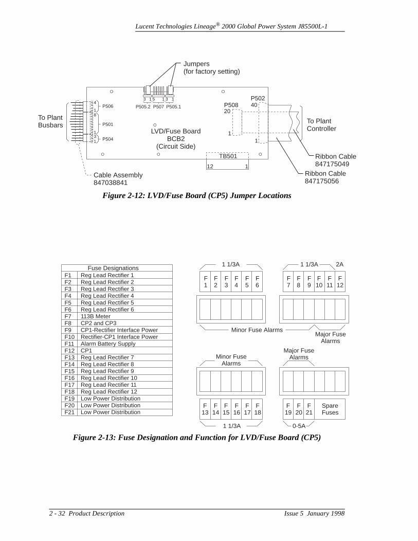
Power/Sense Voltage Fusing: The LVD/Fuse Board has up to18 fuses to distribute power and sense voltages. F501-F506F513-F518 provide battery sense voltage to the regulation leof the rectifiers. F507 provides power and plant voltage sensto the meter circuits of the 113B Control Unit and optional circuit pack CP2. F508 provides power to the optional circuipacks CP2 and CP3. F509 provides power to the rectifier interface circuits on CP1. F510 provides power to the controinterface circuits on the rectifiers. F511 provides power to thABS leads of the 113B Control Unit. F512 provides power to tcircuitry on the 113B Control unit not powered by F507 or F50The LVD/Fuse Board designations F501 through F524 correspond to fuse positions 1 - 24 as shown in Figure 2-13
Major/Minor Fuse Alarms: The LVD/Fuse Board provides Major and Minor Fuse Alarms to the controller. A Major FuseAlarm is generated when F510, F511, F512 or F521-F523 opwhen a plant distribution fuse opens, or when TB501-2 or TB501-4 is tied to the plant voltage. A Minor Fuse Alarm is generated when any one of the fuses F501-F509 or F513-Fopens, when TB501-3 or TB501-5 is connected to the plant voltage, or when one or both of the low voltage detection circuattempts to open the LVD contactor (either under normal operation or in a fault situation; see the following paragraph further details).
Low Voltage Detection for Disconnect/Reconnect Contactor: The LVD/Fuse Board provides sensing of the plant voltage fuse in controlling the low voltage disconnect/reconnect contactor in the battery plant. Although the actual contactor isoptional feature of the battery plant, the sensing circuits andassociated alarms are standard on all controllers. There aresense circuits on the LVD/Fuse Board, configured in a redundfashion so that both circuits must sense a low voltage beforeopening the contactor. P505.1 and P505.2 provide the user a choice of two disconnect voltages. Placing jumpers across 1 and 2 of P505.1 and P505.2 provides a disconnect voltage42.5 volts for 48-volt plants, while placing the jumpers acrospins 2 and 3 provides a disconnect voltage of 40.5 volts.
Issue 5 January 1998 Product Description 2 - 31
Lucent Technologies Lineage® 2000 Global Power System J85500L-1
ToBu
le
Figure 2-12: LVD/Fuse Board (CP5) Jumper Locations
To PlantController
Plantsbars
Cable Assembly847038841
LVD/Fuse BoardBCB2
(Circuit Side)TB501
112
P508P502
20
1
40
1
Jumpers(for factory setting)
Ribbon Cable847175056
Ribbon Cab847175049
3 1 5 1 3 1
P505.2P506
P501
P504
P505.1P5074
18
131
Figure 2-13: Fuse Designation and Function for LVD/Fuse Board (CP5)
Fuse DesignationsF1F2F3F4F5F6F7F8F9F10F11F12F13F14F15F16F17F18F19F20F21
Reg Lead Rectifier 1Reg Lead Rectifier 2Reg Lead Rectifier 3Reg Lead Rectifier 4Reg Lead Rectifier 5Reg Lead Rectifier 6113B MeterCP2 and CP3CP1-Rectifier Interface PowerRectifier-CP1 Interface PowerAlarm Battery SupplyCP1Reg Lead Rectifier 7Reg Lead Rectifier 8Reg Lead Rectifier 9Reg Lead Rectifier 10Reg Lead Rectifier 11Reg Lead Rectifier 12Low Power DistributionLow Power DistributionLow Power Distribution
F1
F7
F2
F8
F3
F9
F4
F10
F13
F16
F19
F5
F11
F14
F17
F20
F6
F12
F15
F18
F21
SpareFuses
1 1/3A 0-5A
Minor FuseAlarms
Major FuseAlarms
Major FuseAlarms
Minor Fuse Alarms
1 1/3A 1 1/3A 2A
2 - 32 Product Description Issue 5 January 1998
Lucent Technologies Lineage® 2000 Global Power System J85500L-1
ia
es
t L e
ll
ent the he ed
r. the
it
ys
e and
suit
e at
se
Information on the state of the detection circuits is provided vtwo LEDs, connections to the controller's Minor Fuse Alarm circuits, and a Form-C contact closure available on the 113BControl Unit. When one or both of the detection circuits sensa low voltage, or if one of the detection circuits fails so that iappears to have detected a low voltage, the yellow LVD/FAILED will illuminate and a Minor Fuse Alarm will be sent to thcontroller. If the battery plant is equipped with the LVD disconnect/reconnect contactor, the red LVD/OPEN LED wiilluminate when the contactor is open either during normal operation when a low voltage is detected or in the unlikely evof a contactor failure. A Form-C contact closure available on 113B Control Unit will also show the status of the contactor. Tred LVD/OPEN LED and Form-C contact closure are powerfrom the battery side of the contactor, while the yellow LVD/FAIL LED is powered from the load side of the contactoIf the rectifiers are powered down and the contactor is open,red LVD/OPEN LED will be illuminated, the yellow LVD/FAIL LED will not be illuminated, the Form-C contact closure will show the contactor as open, and a Minor Fuse Alarm will begiven because the 113B Control Unit sends all alarms whenloses power.
In battery plants without a contactor, the red LVD/OPEN LEDwill never illuminate and the Form-C contact closure will alwashow the non-existent contactor as open.
Low Power Distribution: The LVD/Fuse Board may provide low power distribution for customer applications. Plant voltagis supplied to TB501, pins 6, 7, and 8 via fuses F519, F520, F521 respectively. These three fuses come factory equippedwith 5-ampere ratings. Lower ampacity fuses may be used toparticular applications. Typical applications include remote monitoring systems, alarm indicator panels, temperature transducers, or any other equipment that requires plant voltag
Caution
The two jumpers must be set for the same threshold. Eachjumper sets the threshold for one of the two redundant sencircuits. If the jumpers are set for different thresholds, the lower threshold will actually control the contactor since bothcircuits must sense a low voltage before opening the contactor.
Issue 5 January 1998 Product Description 2 - 33
Lucent Technologies Lineage® 2000 Global Power System J85500L-1
rm
F524. ere uses t e
) in
ius . ). 67°
s 6
e
° F
to ill ed.
t
itor
low ampacities. If any of these fuses opens, a Major Fuse Alais generated.
Spare Fuses: The LVD/Fuse Board also provides holders forthree spare fuses. These fuses are labeled F522, F523, and The holders come equipped from the factory with 1-1/3 amprated fuses. These may be replaced with any ampere rating fthat a customer prefers for a particular application. Note thathese fuse holders are not connected to plant power or to thcontroller's alarm circuitry.
Thermal (Slope/Step) Compensation Feature: The 216A ECS Thermal Compensation Unit, used in conjunction with the BMD1 LVD/R Fuse Board circuit pack, provides reduction inplant voltage for measured temperatures above 77° F (25° Ca slope plus step manner. See Figure 2-14.
The BMD1 reduces the plant voltage 72mV per degree Celsfor a maximum of 2.0Vdc below the uncompensated voltageThe compensation will stop at approximately 127.4° F (53° CFor temperatures higher than 127.4° F (53° C) but less than 1F (75° C), a constant voltage drop of 2.0Vdc below the uncompensated voltage will be maintained. For temperaturehigher than 167° F (75° C) the plant voltage will be reducedvolts below the uncompensated 77° F (25° C) voltage.
The plant voltage will be raised 4.0Vdc when the temperaturreturns to 149° F (65° C). A green indicator will illuminate toreflect an active module. A yellow indicator will illuminate to reflect temperatures above 127.4° F (53° C) and will blink toreflect temperatures above 167° F (75° C).
The 216A Thermal Compensation Unit also has the ability toincrease the plant voltage for sensor temperatures below 77(25° C).
The plant voltage will be increased 72mV per degree Celsiusa maximum of 2.0Vdc above the float voltage. The BMD1 wbe shipped from the factory with this margining feature disabl
The 216A Thermal Compensation Unit will accept up to eighthermistors (two per battery string). Up to five 216A modulescan be daisy-chained together, which gives the ability to monup to 20 battery strings.
2 - 34 Product Description Issue 5 January 1998
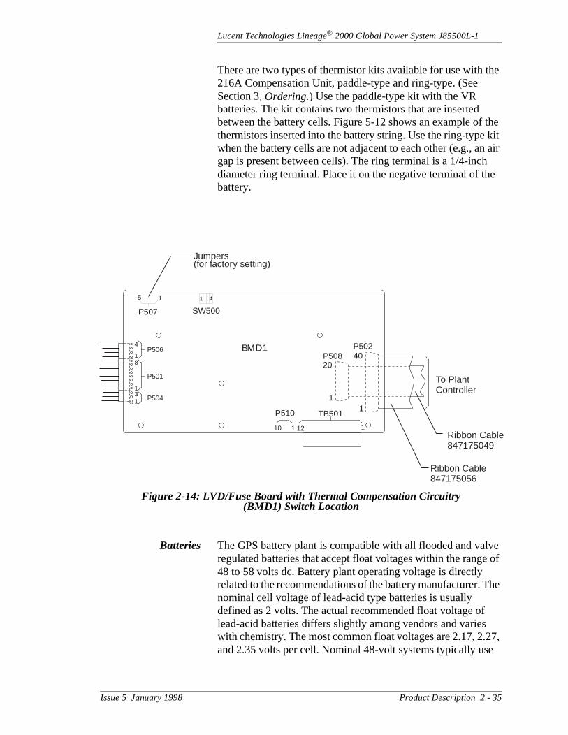
Lucent Technologies Lineage® 2000 Global Power System J85500L-1
he
the kit n air e
ve e of
The
27, e
There are two types of thermistor kits available for use with t216A Compensation Unit, paddle-type and ring-type. (See Section 3, Ordering.) Use the paddle-type kit with the VR batteries. The kit contains two thermistors that are inserted between the battery cells. Figure 5-12 shows an example ofthermistors inserted into the battery string. Use the ring-typewhen the battery cells are not adjacent to each other (e.g., agap is present between cells). The ring terminal is a 1/4-inchdiameter ring terminal. Place it on the negative terminal of thbattery.
Batteries The GPS battery plant is compatible with all flooded and valregulated batteries that accept float voltages within the rang48 to 58 volts dc. Battery plant operating voltage is directly related to the recommendations of the battery manufacturer. nominal cell voltage of lead-acid type batteries is usually defined as 2 volts. The actual recommended float voltage oflead-acid batteries differs slightly among vendors and varieswith chemistry. The most common float voltages are 2.17, 2.and 2.35 volts per cell. Nominal 48-volt systems typically us
Figure 2-14: LVD/Fuse Board with Thermal Compensation Circuitry (BMD1) Switch Location
SW500P507
P510 TB501
112110
5 1 1 4
BMD1
Jumpers(for factory setting)
P506
P501
P504
4
18
131
To PlantController
P508P502
20
1
40
1
Ribbon Cable847175056
Ribbon Cable847175049
Issue 5 January 1998 Product Description 2 - 35

Lucent Technologies Lineage® 2000 Global Power System J85500L-1
to m
r the es ac
AC
, 4, kers
and A er us
the ll
nd
24-cell battery strings for float voltages that range from 52.0856.40 volts per string. The float voltage per string, the minimustring voltage at the end of discharge, and the maximum charging voltage per string must be provided by the battery vendor in order to properly configure the battery plant.
AC Distribution The ac distribution assembly consists of an ac circuit breakebox prewired to each rectifier in the system, terminations for commercial ac, and ac voltage and current monitoring devicfor monitoring ac status via the ECS controller (L1 only). The distribution schemes are shown in Figures 2-15 and 2-15A.
The L1 configuration consists of an ac circuit breaker box located at the top of the cabinet that is equipped with twelvecircuit breakers, earth ground, and neutral connection points.power is sourced from a 380/220V, 50/60Hz wye derived service (line to neutral, 4-wire + PE). Line 1 feeds breakers 17, 10; Line 2 feeds breakers 2, 5, 8, 11; and Line 3 feeds brea3, 6, 9, 12. Each circuit breaker is prewired to one rectifier position on a rectifier shelf.
The L20 configuration consists of an ac circuit breaker box located at the top of the cabinet equipped with earth ground phase 1(R), 2(S), 3(T) connection points, and a two-pole 30circuit breaker wired to each rectifier in the cabinet. AC powis sourced from 208/240Vac, 50-60Hz, three-phase, delta plprotective earth ground (3-wire + PE). All ac wiring to the shelves is enclosed in channels that run along both sides ofcabinet. Snap-on covers may be removed to access or instawiring to each of the shelves. Wiring is 10 gauge (2.5mm) acolor coded for easy reference as follows:
Earth Ground Green/YellowNeutral BlueLine 1 BrownLine 2 BlackLine 3 Black/White
2 - 36 Product Description Issue 5 January 1998
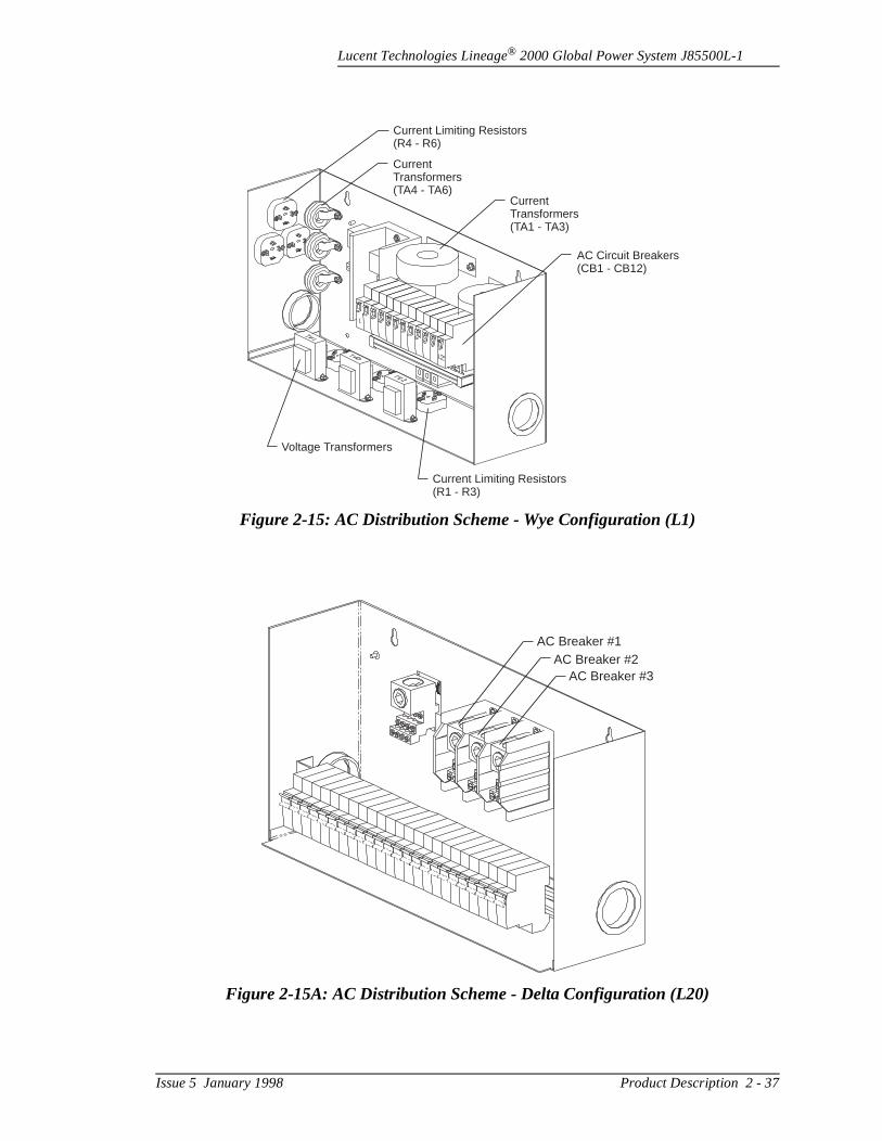
Lucent Technologies Lineage® 2000 Global Power System J85500L-1
Figure 2-15: AC Distribution Scheme - Wye Configuration (L1)
CurrentTransformers(TA4 - TA6)
CurrentTransformers(TA1 - TA3)
AC Circuit Breakers(CB1 - CB12)
Current Limiting Resistors(R1 - R3)
Current Limiting Resistors(R4 - R6)
Voltage Transformers
Figure 2-15A: AC Distribution Scheme - Delta Configuration (L20)
AC Breaker #1AC Breaker #2
AC Breaker #3
Issue 5 January 1998 Product Description 2 - 37
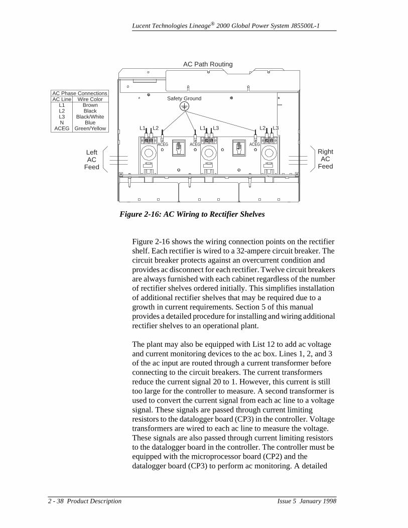
Lucent Technologies Lineage® 2000 Global Power System J85500L-1
ier he ers ber
n
al
ge 3 re
ill r is age
ge e. tors be
Figure 2-16 shows the wiring connection points on the rectifshelf. Each rectifier is wired to a 32-ampere circuit breaker. Tcircuit breaker protects against an overcurrent condition andprovides ac disconnect for each rectifier. Twelve circuit breakare always furnished with each cabinet regardless of the numof rectifier shelves ordered initially. This simplifies installatioof additional rectifier shelves that may be required due to a growth in current requirements. Section 5 of this manual provides a detailed procedure for installing and wiring additionrectifier shelves to an operational plant.
The plant may also be equipped with List 12 to add ac voltaand current monitoring devices to the ac box. Lines 1, 2, andof the ac input are routed through a current transformer befoconnecting to the circuit breakers. The current transformers reduce the current signal 20 to 1. However, this current is sttoo large for the controller to measure. A second transformeused to convert the current signal from each ac line to a voltsignal. These signals are passed through current limiting resistors to the datalogger board (CP3) in the controller. Voltatransformers are wired to each ac line to measure the voltagThese signals are also passed through current limiting resisto the datalogger board in the controller. The controller mustequipped with the microprocessor board (CP2) and the datalogger board (CP3) to perform ac monitoring. A detailed
Figure 2-16: AC Wiring to Rectifier Shelves
AC LineL1L2L3N
ACEG
Wire ColorBrownBlack
Black/WhiteBlue
Green/Yellow
AC Phase Connections
LeftAC
Feed
RightAC
Feed
AC Path Routing
ACEG ACEG ACEG
Safety Ground
L1 L1 L2L2 L3 L3
2 - 38 Product Description Issue 5 January 1998
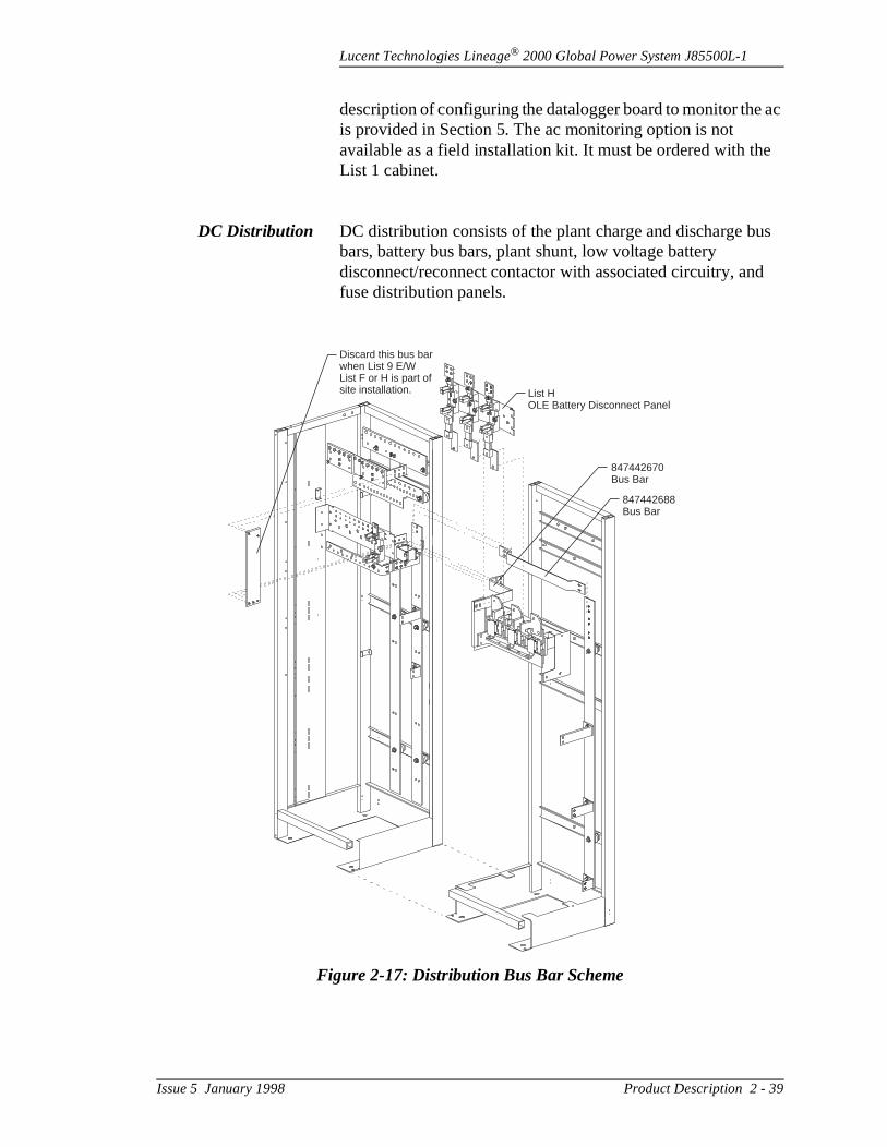
Lucent Technologies Lineage® 2000 Global Power System J85500L-1
ac
e
us
d
description of configuring the datalogger board to monitor theis provided in Section 5. The ac monitoring option is not available as a field installation kit. It must be ordered with thList 1 cabinet.
DC Distribution DC distribution consists of the plant charge and discharge bbars, battery bus bars, plant shunt, low voltage battery disconnect/reconnect contactor with associated circuitry, anfuse distribution panels.
Figure 2-17: Distribution Bus Bar Scheme
Discard this bus barwhen List 9 E/WList F or H is part ofsite installation. List H
OLE Battery Disconnect Panel
847442670Bus Bar
847442688Bus Bar
Issue 5 January 1998 Product Description 2 - 39

Lucent Technologies Lineage® 2000 Global Power System J85500L-1
h)
e fuse
e ac
per at on
us.
arge
or g ttery ,
ons.
a
of ly
e ers lts
Distribution Bus Bars: Figure 2-17 shows the busing schemefor the plant. The copper bus bars (plated with a solder finisused in the Global Power System are sized to provide a 600-ampere current carrying capacity.
Two sets of bus bars extend vertically along the back of the rectifier cabinet. The charge bus (-48 volt) is on the right sidand the charge return bus is on the left. Rectifier shelves and panels connect directly to these buses as shown.
Cabling from batteries is terminated to the battery bus and charge return bus located at the top of the cabinet behind thbox. The charge return bus is equipped with twelve M10 connection points designed to accommodate single hole copcrimp lug connectors. Battery return cabling (+) is terminatedthis bus. The battery bus is equipped with ten M10 connectipoints. Battery cabling is terminated to this bus.
The discharge return bus is sized to accept the load return cabling from each fuse distribution panel. This bus is locatedbelow the charge return bus. There are twenty-eight M8 connection points and twelve M10 connection points on this b
The supplemental cabinet, shown in Figure 2-17, has one chbus extending vertically along the back of the cabinet. It is connected back through to the charge return bus via an interconnecting horizontal bus bar. Fuse panels or battery disconnect panels connect directly to the buses as shown.
The Global Power System offers several additional options fconnecting batteries to the system. These include connectindirectly to the plant buses as discussed, connecting to the bafuse-disconnect panel located in the top distribution positionand the use of a low voltage battery disconnect/reconnect contactor. These options are discussed in the following secti
Plant Shunt: A current shunt is a sensing device that providesmillivolt signal proportional to the current flowing through it. The millivolt-to-ampere ratio of the shunt is the dc resistancethe shunt (in milliohms) that is thermally stable and accurateknown.
The current shunt in the J85500L-1 is connected between thcharge return bus and the discharge return bus. It is used tomeasure the total current supplied to the load from the rectifiand/or batteries. The shunt has a full scale rating of 50 millivo
2 - 40 Product Description Issue 5 January 1998
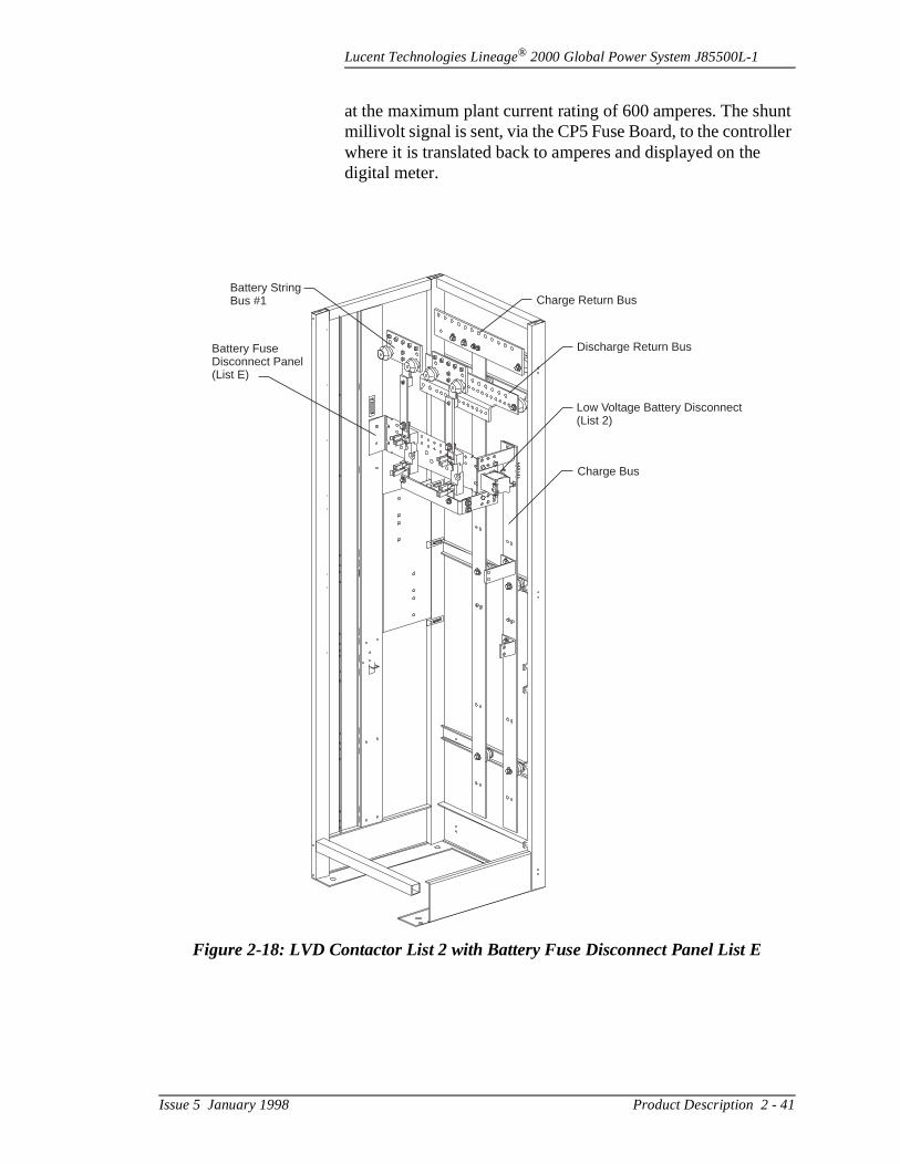
Lucent Technologies Lineage® 2000 Global Power System J85500L-1
unt ler
at the maximum plant current rating of 600 amperes. The shmillivolt signal is sent, via the CP5 Fuse Board, to the controlwhere it is translated back to amperes and displayed on thedigital meter.
Figure 2-18: LVD Contactor List 2 with Battery Fuse Disconnect Panel List E
Battery StringBus #1
Battery FuseDisconnect Panel(List E)
Charge Return Bus
Discharge Return Bus
Low Voltage Battery Disconnect(List 2)
Charge Bus
Issue 5 January 1998 Product Description 2 - 41
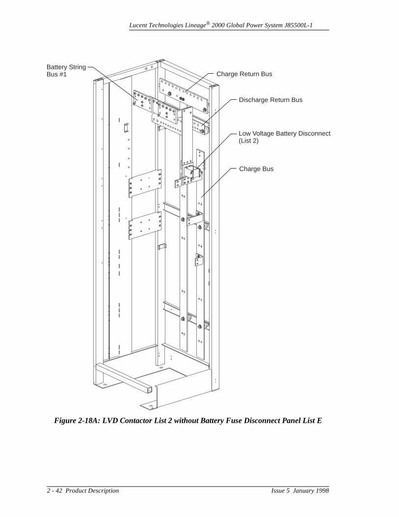
Lucent Technologies Lineage® 2000 Global Power System J85500L-1
Figure 2-18A: LVD Contactor List 2 without Battery Fuse Disconnect Panel List E
Battery StringBus #1 Charge Return Bus
Discharge Return Bus
Low Voltage Battery Disconnect(List 2)
Charge Bus
2 - 42 Product Description Issue 5 January 1998
Lucent Technologies Lineage® 2000 Global Power System J85500L-1
the ic
This the
ave from ad
and
e
own
se
P5 wer
the
s. ing
n n
tor
Low Voltage Battery Disconnect/Reconnect (LVD/R) Feature: To prevent costly damage due to deep discharges,J85500L-1 List 1 may be equipped with an optional automatbattery disconnect feature. The LVD/R contactor is used to either connect or disconnect the charge bus and battery bus.disconnect is designed to isolate batteries from the load whenplant voltage reaches the lowest usable battery voltage. Thedisconnect level is below the operating range of most load equipment, in which case service to the load would already hbeen lost. The disconnect does not separate the load circuits the rectifiers, enabling the rectifiers to begin powering the loas soon as ac power is restored.
List 2 provides a 600-ampere contactor and interconnectionhardware for installing the contactor between the battery bus the charge bus. There are two methods for installing the contactor. If the battery fuse-disconnect panel is ordered, thcontactor is installed as shown in Figure 2-18. If there is no battery fuse-disconnect panel, the contactor is installed as shin Figure 2-18A.
The LVD/R contactor is controlled by circuitry on the CP5 FuBoard. The LVD circuit on CP5 monitors the battery bus voltage. When the voltage drops below a preset level, the CFuse Board senses the low voltage condition and removes pofrom the contactor. This opens the connection between the charge bus and battery bus, disconnecting the batteries fromrectifiers and the load. The user has the choice of setting thedisconnect threshold voltage at either 40.5 volts or 42.5 voltWhen the contactor is open and the rectifiers are not deliverpower, the controller is unpowered as well. In this state, the controller displays and LEDs are extinguished and various alarms are issued to the alarm reporting center.
The red LVD OPEN and yellow LVD FAIL LEDs are located othe top dc distribution panel door. The red LVD OPEN LED othe CP5 Fuse Board lights whenever the contactor is open, during a normal disconnect or in the unlikely event of a contacfailure. The LVD sensing circuitry on CP5 is redundant. A failure of either voltage detector circuit lights the yellow LVDFAIL LED but the contactor will stay closed. A Fuse Alarm Minor (MNF) is issued when an LVD circuit fails, lighting a yellow LED on the controller front panel and sending PowerMinor (PMN) alarms to the reporting center.
Issue 5 January 1998 Product Description 2 - 43
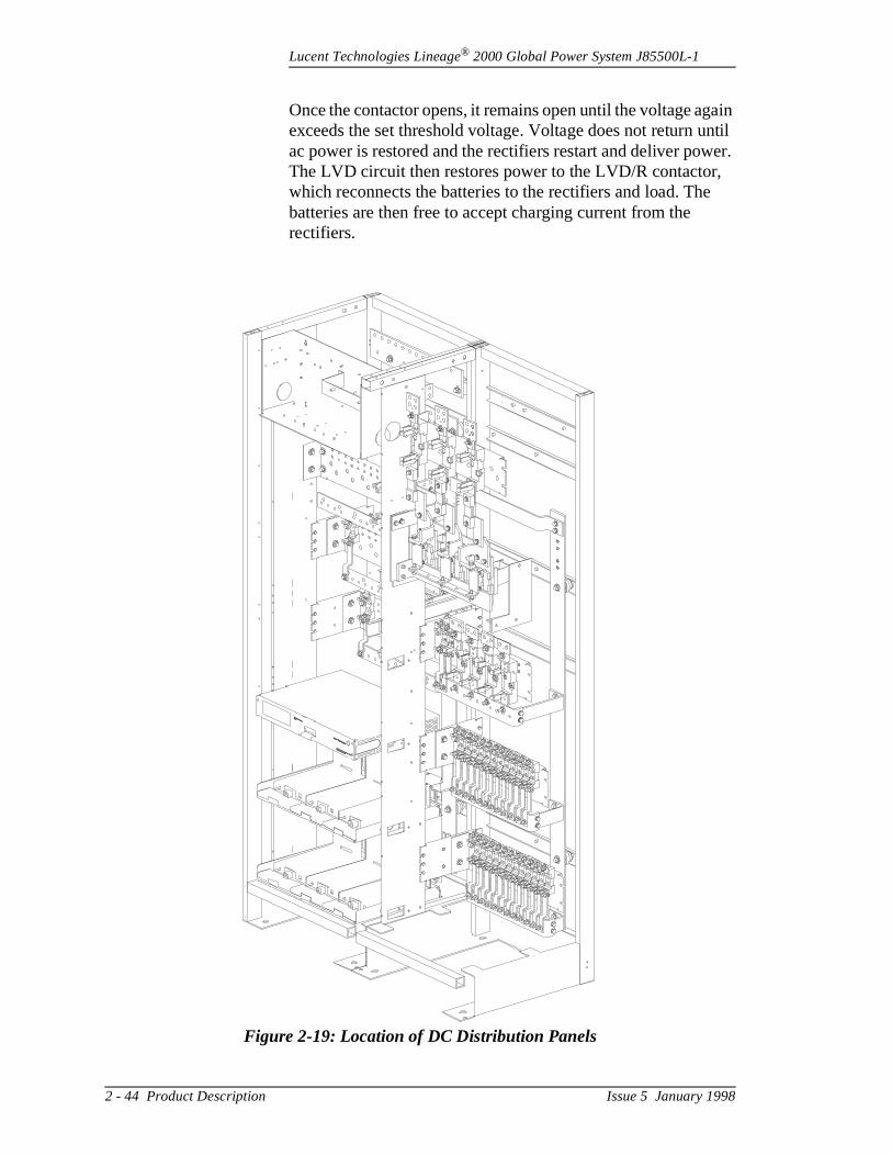
Lucent Technologies Lineage® 2000 Global Power System J85500L-1
gain ntil er.
,
Once the contactor opens, it remains open until the voltage aexceeds the set threshold voltage. Voltage does not return uac power is restored and the rectifiers restart and deliver powThe LVD circuit then restores power to the LVD/R contactorwhich reconnects the batteries to the rectifiers and load. Thebatteries are then free to accept charging current from the rectifiers.
Figure 2-19: Location of DC Distribution Panels
LINEAGE 2000
ECS
LINEAGE 2000
ECS
Lucent Technologies
Lucent Technologies
CONTAINS STATIC SENSITIVE DEVICES
USE ESD WRIST STRAP
CONTAINS STATIC SENSITIVE DEVICES
USE ESD WRIST STRAP
2 - 44 Product Description Issue 5 January 1998
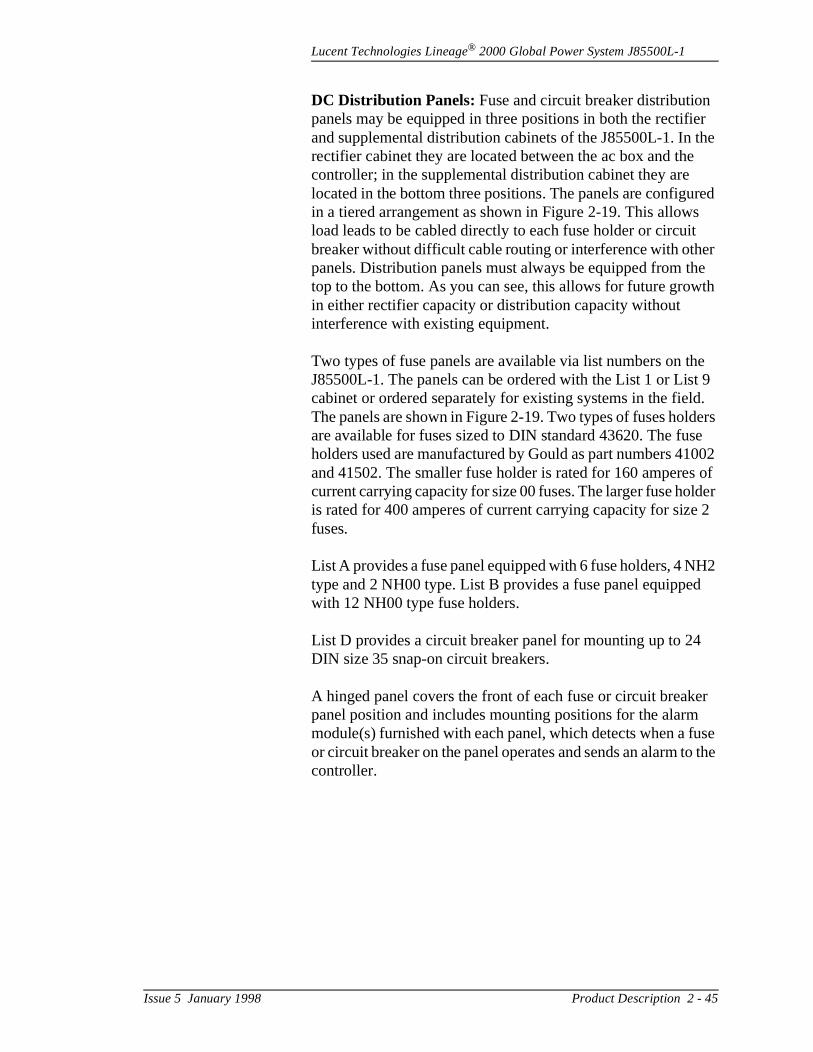
Lucent Technologies Lineage® 2000 Global Power System J85500L-1
er the
red s t r e th
e t 9 d. ers e 002
s of lder 2
H2 d
er use o the
DC Distribution Panels: Fuse and circuit breaker distributionpanels may be equipped in three positions in both the rectifiand supplemental distribution cabinets of the J85500L-1. In rectifier cabinet they are located between the ac box and thecontroller; in the supplemental distribution cabinet they are located in the bottom three positions. The panels are configuin a tiered arrangement as shown in Figure 2-19. This allowload leads to be cabled directly to each fuse holder or circuibreaker without difficult cable routing or interference with othepanels. Distribution panels must always be equipped from thtop to the bottom. As you can see, this allows for future growin either rectifier capacity or distribution capacity without interference with existing equipment.
Two types of fuse panels are available via list numbers on thJ85500L-1. The panels can be ordered with the List 1 or Liscabinet or ordered separately for existing systems in the fielThe panels are shown in Figure 2-19. Two types of fuses holdare available for fuses sized to DIN standard 43620. The fusholders used are manufactured by Gould as part numbers 41and 41502. The smaller fuse holder is rated for 160 amperecurrent carrying capacity for size 00 fuses. The larger fuse hois rated for 400 amperes of current carrying capacity for sizefuses.
List A provides a fuse panel equipped with 6 fuse holders, 4 Ntype and 2 NH00 type. List B provides a fuse panel equippewith 12 NH00 type fuse holders.
List D provides a circuit breaker panel for mounting up to 24DIN size 35 snap-on circuit breakers.
A hinged panel covers the front of each fuse or circuit breakpanel position and includes mounting positions for the alarmmodule(s) furnished with each panel, which detects when a for circuit breaker on the panel operates and sends an alarm tcontroller.
Issue 5 January 1998 Product Description 2 - 45
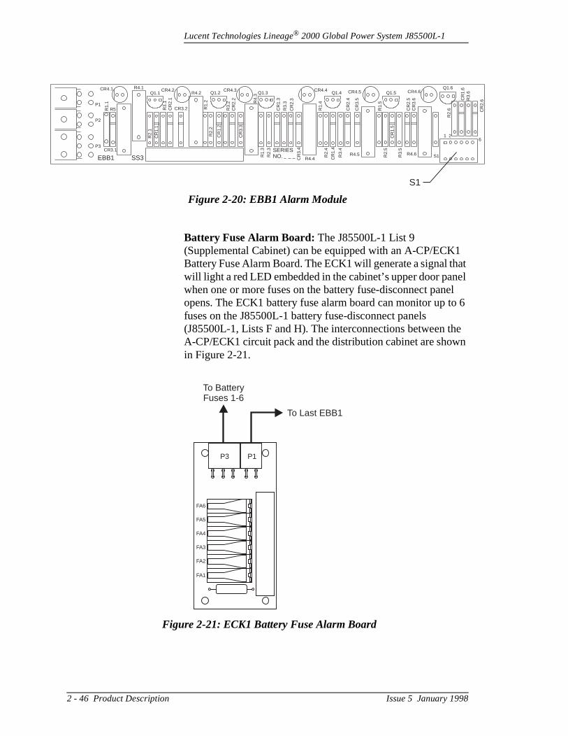
Lucent Technologies Lineage® 2000 Global Power System J85500L-1
1 at el
el o 6
he n
6
CR
2.6
Battery Fuse Alarm Board: The J85500L-1 List 9 (Supplemental Cabinet) can be equipped with an A-CP/ECKBattery Fuse Alarm Board. The ECK1 will generate a signal thwill light a red LED embedded in the cabinet’s upper door panwhen one or more fuses on the battery fuse-disconnect panopens. The ECK1 battery fuse alarm board can monitor up tfuses on the J85500L-1 battery fuse-disconnect panels (J85500L-1, Lists F and H). The interconnections between tA-CP/ECK1 circuit pack and the distribution cabinet are showin Figure 2-21.
Figure 2-20: EBB1 Alarm Module
CR4.1 R4.1
P1
P2
P3
EBB1 SS3CR3.1
R1.
1R5
R2.
1
R3.
1
CR
1.1
CR
2.1
Q1.1CR4.2
R4.2
CR3.2
Q1.2
R1.
2
R3.
2C
R2.
2
CR4.3 CR4.4 CR4.5
R2.
2
CR
1.2
CR
3.3
R1.
3R
2.3 SERIES
NO. CR
3.4
R4.
3 Q1.3 Q1.4
CR
1.3
R3.
3
CR
2.3
R4.4
R2.
4
R3.
4
CR
1.4
R4.5
R1.
4
CR
2.4
CR
3.5
R1.
5
Q1.5
CR
2.5
CR
3.6
CR4.6
R2.
5
CR
1.5
R3.
5
R4.6 S1
Q1.6
1 2
R3.
6
R2.
6
CR
1.6
S1
Figure 2-21: ECK1 Battery Fuse Alarm Board
P1P3
FA6
FA5
FA4
FA3
FA2
FA1
To Last EBB1
To BatteryFuses 1-6
2 - 46 Product Description Issue 5 January 1998
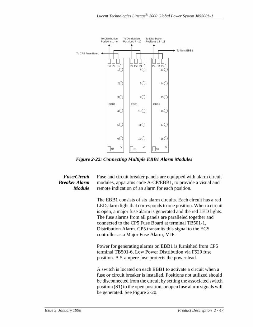
Lucent Technologies Lineage® 2000 Global Power System J85500L-1
uit d
ed uit hts.
a ld itch will
Fuse/CircuitBreaker Alarm
Module
Fuse and circuit breaker panels are equipped with alarm circmodules, apparatus code A-CP/EBB1, to provide a visual anremote indication of an alarm for each position.
The EBB1 consists of six alarm circuits. Each circuit has a rLED alarm light that corresponds to one position. When a circis open, a major fuse alarm is generated and the red LED ligThe fuse alarms from all panels are paralleled together and connected to the CP5 Fuse Board at terminal TB501-1, Distribution Alarm. CP5 transmits this signal to the ECS controller as a Major Fuse Alarm, MJF.
Power for generating alarms on EBB1 is furnished from CP5terminal TB501-6, Low Power Distribution via F520 fuse position. A 5-ampere fuse protects the power lead.
A switch is located on each EBB1 to activate a circuit when fuse or circuit breaker is installed. Positions not utilized shoube disconnected from the circuit by setting the associated swposition (S1) to the open position, or open fuse alarm signals be generated. See Figure 2-20.
Figure 2-22: Connecting Multiple EBB1 Alarm Modules
EBB1 EBB1 EBB1
S1 S1 S1
P3 P3 P3P2 P2 P2P1 P1 P11
2
3
4
5
6
7
8
9
10
11
12
13
14
15
16
17
18
To Next EBB1To CP5 Fuse Board
To DistributionPositions 1 - 6
To DistributionPositions 7 - 12
To DistributionPositions 13 - 18
Issue 5 January 1998 Product Description 2 - 47
Lucent Technologies Lineage® 2000 Global Power System J85500L-1
or
n
e
y and
ated ars ery n to by f
ped res nts.
et.
rge
be
ic ure
are 630 ing
tal
The List A fuse panel requires one EBB1 circuit module. TheList B requires two; the List D requires four. A six-pin connecton the EBB1 provides the input signal from each holder. Thefour pin connectors provide ground from the discharge returbus, power from CP5 (TB501-6) to the circuit, and the fuse alarm signal to CP5 (TB501-1). When multiple EBB1s are connected together, they are simply interconnected from onboard to the next as shown in Figure 2-22.
Battery FuseDisconnect Panel
The other option for terminating battery cabling is to a batterfuse-disconnect panel. The panels are furnished with Lists E F. List E is located in the top distribution panel of the main rectifier cabinet. This panel is designed for terminating two strings of batteries. Each string is connected to a bus bar locat the top of the cabinet behind the ac box. These two bus bare each equipped with five M10 connection points. The battis bused across a 600-ampere current monitoring shunt dowa fuse holder on the panel. The fuse holder is manufacturedGould as part number 41602 and is rated for 630 amperes ocurrent carrying capacity for size 3 fuses.
List F terminates three strings of batteries. The panel is equipwith three Gould 41602 type fuse holders rated at 630 ampefor size 3 fuses and three 600-ampere current monitoring shuIt is located at the top of the supplemental distribution cabin
From the fuse holders, the battery is bused to the vertical chabus of the main cabinet. The shunts may be wired to the datalogger board (CP3) in the controller. The controller mustequipped with the microprocessor board (CP2) and the datalogger board (CP3) to perform this monitoring. The “BasConfiguration and Options” paragraph describes the procedfor configuring the datalogger board (CP3) to perform shuntmonitoring.
Off-LineEqualize Panel
List H terminates three strings of batteries with an off-line equalize feature. The fuse panel and associated equipment equipped with three Gould 41602 type fuse holders rated at amperes for size 3 fuses, three 600-ampere current monitorshunts, and three 1200-ampere battery transfer contactor switches. It is also located at the top of the List 9 supplemendistribution cabinet. See Figure 2-19.
2 - 48 Product Description Issue 5 January 1998
Lucent Technologies Lineage® 2000 Global Power System J85500L-1
ign, ct are and
ched the ac List ted
P)
oost
ing
er d
the the
turn
lize
re
nal
AppearancePackages
The Global Power System cabinet is an open framework deswhich allows easy access for installation personnel to connecabling and equipment to the cabinet. Side and rear covers required to enclose the plant after installation. Both the side rear covers are ordered as List 10. If both a rectifier and supplemental distribution cabinet are present, only two side covers and two rear covers are required. Plastic clips are attato the sides of the cabinet. The side cover is then hooked ontoclips. The List 1 and List 9 cabinets have doors covering theand dc distribution. Center-opening doors may be ordered as11 to provide an aesthetically pleasing look for systems locain high visibility areas. These doors are similar in style and appearance to the doors used on the 5ESS switch system.
Boost ChargePanel
The J85500L-1 Group H includes a boost charge panel (BCthat is mounted in the supplemental distribution cabinet, as shown in Figure 2-2A and Figure 2-23. Boost charging is a system feature since the load and all batteries receive the bcharge voltage. The BCP activates the boost mode of the rectifiers through the plant controller to reduce battery chargtime after a discharge. (The boost mode of the rectifier is indicated with an LED labeled EQ; labels are provided to covthe EQ with BST (see “Boost Charge Panel (BCP) Wiring anTest” in Section 5.)
The BCP may be operated in a manual, timed manual, or automatic mode. In the manual modes, the operator selectsduration of the boost charge and activates the system. Whentime period has elapsed, the BCP signals the controller to rethe rectifiers to float mode. For the automatic mode, the BCPmonitors the plant controller for a battery on discharge (BD)status. The BCP times the BD period and activates the equamode depending on the length of the BD. Again, the systemreturns to the float mode after the specified boost period.
Boost Charge Unit Feature Summary:
• The BCP operates with the Galaxy, CCS, MCS, or ECS family of Lucent Technologies controllers, the 400-ampeferroresonant rectifier, and all switch mode rectifiers.
• The BCP has the ability to accept a Reserve On-Line sig(RO) from the engine and prevent the rectifiers from operating in the boost mode while the battery plant is onengine.
Issue 5 January 1998 Product Description 2 - 49

Lucent Technologies Lineage® 2000 Global Power System J85500L-1
it
ual set
s
.
n.
o
d
• The BCP has the ability to accept both the Power Minor (PMN) and Power Major (PMJ) alarms and prevent the rectifiers from operation in the boost mode.
• Failure of the BCP will disable the boost feature. If the unis in the boost charge mode when it fails, it will force all rectifiers back to “float.”
• Boost charge can be initiated either by automatic or manmeans. The operational parameters of the panel can beon the unit.
Front Panel Indications:
• A yellow LED labeled “Bst” lights whenever the BCP sendthe signal for the plant to go into the boost mode.
• A green LED labeled NORMAL lights whenever the BCPis either in the boost mode or the float mode.
• A red LED labeled FAIL lights when the BCP has failed. When the red LED lights, the green LED does not.
Front Panel Switches:
• A three-position, momentary switch that, when operated,will place the plant in either the float or boost mode.
• A twelve-position rotary switch labeled “Boost Time (Hours)” performs the manual and timed boost functions
Programming Switches:
• A four-position DIP switch, labeled “Option,” is located onthe rear of the unit. Positioning the first DIP switch in theON position disables the auto-boost function. For the auto-boost mode, this switch must be in the OFF positioPositioning the second DIP switch in the ON position allows for +24-volt boost charge operation. The other twpositions are not used.
• An eight-position DIP switch labeled “Constant” is locateon the rear of the unit. Placing a single switch in the ONposition will set “N” to the corresponding number for thefollowing algorithm: e.g., if DIP switch 6 is on, the boosttime will be six times as long as the period during whichthe batteries were on discharge.
2 - 50 Product Description Issue 5 January 1998

Lucent Technologies Lineage® 2000 Global Power System J85500L-1
cks
e
ing s trol rns
sed. lant he
ng
he r d in d in
BOOST TIME = (BD TIME) x N
where N = 1, 2, 3, 4, 5, 6, 7, or 8
Input Signals and Output Signals:
The BCP has three connectorized, screw-down terminal blolocated in the back of the unit.
• Terminal TB1 is for the input power.
• Terminal TB2 is for the input signals: Battery on Discharg(BD), Power Minor (PMN) and Power Major (PMJ) alarms, and Reserve On-Line (RO) status.
• Terminal TB3 is for the output signals listed below:
– BCP Fail – BCP ON– BCP OFF– Remote Monitor
Off-LineEqualize Panel
The J85500L-1 Group H also includes an off-line equalize (OLE) panel that is mounted in the supplemental distributioncabinet (refer to Figure 2-2A and Figure 2-23). The OLE monitors the battery switches and a designated off-line chargrectifier switch for off-line indicators. Once the OLE determinethat the battery and rectifier are ready, the OLE assumes conof the rectifier and activates the equalize mode. The OLE retuthe rectifier to the float mode after the selected time has elapThe operator reconnects the battery and the rectifier to the pbus and the plant controller resumes control of the rectifier. Tplant controller still receives any alarms from the rectifier durithe process.
Off-line equalize requires communication among the plant controller, the rectifiers, and the supplemental distribution cabinet. To provide off-line equalize, a specially equipped rectifier shelf is required that contains a contactor switch in tleft rectifier slot. This contactor switch allows the third rectifieto be switched between the load bus and the OLE bus locatethe supplemental distribution cabinet. The batteries must beconnected through the battery fuse disconnect panel containethe List H equipment. This connects the batteries through a 1200-ampere battery transfer contactor that can be switched
Issue 5 January 1998 Product Description 2 - 51

Lucent Technologies Lineage® 2000 Global Power System J85500L-1
a
CS
om
he
se
dy
s off
od or
from the battery bus to the OLE bus. When the rectifier and battery string are switched to the off-line position, the OLE isactivated.
Equalize Panel Features:
• The equalize panel operates with Lucent Technologies Econtrollers and the 364A switchmode rectifiers.
• The equalize function can only be initiated if the battery string and the designated rectifier have been isolated frthe load.
• The equalize panel is used to interface the controller to tdesignated equalize rectifier in the plant. As such, the equalize panel will:
– Provide the rectifier with a voltage, via the remote senleads, to allow the rectifier output to increase to the desired equalize voltage.
– Manage the signal flow between the rectifier and the controller during the equalize period.
– Time the equalize period.
– Provide equalize control and status to the field maintenance personnel.
Front PanelIndicators
• A yellow LED labeled BIE (Battery In Equalize) indicatesthat a battery string has been placed “off line” and is reafor Off-Line Equalization.
• A yellow LED labeled RIE (Rectifier In Equalize) indicatethat the designated rectifier of the plant has been takenline and is available for equalize charging of the batterystring in BIE.
• A yellow LED labeled “Eql” indicates that a string of batteries is being equalized via the designated equalizerectifier of the plant.
• A yellow LED labeled ETO indicates that a battery stringwas placed in the equalize mode for a specific time periand that time period has expired. That battery string cannow be placed back on line and another string equalizedthe rectifier can be placed back into “normal” service.
2 - 52 Product Description Issue 5 January 1998
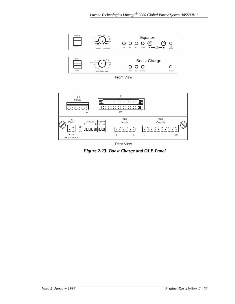
Lucent Technologies Lineage® 2000 Global Power System J85500L-1
Figure 2-23: Boost Charge and OLE Panel
Equalize
Equalize Time (Hours)Float
128
4
48
4440
1620
24
28
3236
BIE RIE Eql ETO EqlBus
EqlAdjust
Equalize
Boost Charge
Fail Bst Normal Reset
42
Manual
22
2018
68
10
12
1416
Boost Time (Hours)
Boost
Float
TB4Inputs
1 6
P2
P3
TB3Outputs
TB2Inputs
1 6 1 10
TB1Power
-48 or +24 VDC
On
Off
Constant Option1 8 1 4
Front View
Rear View
Issue 5 January 1998 Product Description 2 - 53
Lucent Technologies Lineage® 2000 Global Power System J85500L-1
re.
20 CS
ars, at
g the r ery es er of ” the
mer e and
ide ist
put, l nd
3 Ordering
Ordering Information
Table 3-A provides a summary of the J85500L-1 List structuA detailed description of each of the options on the Global Power System is presented in Section 2.
The J85500L-1 is ordered with List (L) numbers. Lists 1 and are the main lists that provide the cabinet equipped with an Econtroller, two rectifier shelves, charge and discharge bus bplant shunt, and ac circuit breaker box. List 9 is a main list thprovides a supplementary distribution cabinet. The remaininlists are supplementary lists that can be ordered in addition tomain lists to customize the system to meet specific customerequirements. For example, List 2 provides a low voltage battdisconnect/reconnect feature for a List 1 cabinet, List 3 providan additional rectifier shelf, List 10 provides a side or rear covfor the cabinet, List 11 provides a set of front center openingdoors and Lists A, B, and E provide distribution panels. Eachthese Lists may be ordered separately or as “Equipped With(E/W) items. This means that they are ordered in addition to main list and will be installed at the factory. If these lists are ordered as separate items, they will be shipped to the custoin separate containers for assembly during installation. SomLists are always ordered separately. Lists 4, 5, 7, 8, K1, K2, K3 provide equipment that is plugged into a system during installation or as add-on kits to an operational system. List 4furnishes a rectifier. Lists 5, 7, and 8 provide feature enhancement boards for the controller, Lists K1 and K2 provkits to modify a fuse panel with additional fuse holders, and LK3 provides a kit to add off-line equalize to a system. As an example, to order a system equipped with delta derived ac in10W-voltage disconnect, CP2 controller circuit pack, thermacompensation, one fuse panel with four NH2 fuse holders, aoff-line equalize, the following would be ordered:
Issue 5 January 1998 Ordering 3 - 1
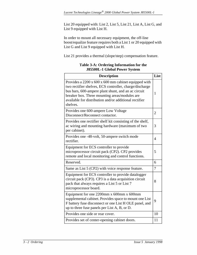
Lucent Technologies Lineage® 2000 Global Power System J85500L-1
d
ith
e.
List 20 equipped with: List 2, List 5, List 21, List A, List G, anList 9 equipped with List H.
In order to mount all necessary equipment, the off-line boost/equalize feature requires both a List 1 or 20 equipped wList G and List 9 equipped with List H.
List 21 provides a thermal (slope/step) compensation featur
Table 3-A: Ordering Information for the J85500L-1 Global Power System
Description List
Provides a 2200 x 600 x 600 mm cabinet equipped with two rectifier shelves, ECS controller, charge/discharge bus bars, 600-ampere plant shunt, and an ac circuit breaker box. Three mounting areas/modules are available for distribution and/or additional rectifier shelves.
1
Provides one 600-ampere Low Voltage Disconnect/Reconnect contactor.
2
Provides one rectifier shelf kit consisting of the shelf, ac wiring and mounting hardware (maximum of two per cabinet).
3
Provides one -48-volt, 50-ampere switch mode rectifier.
4
Equipment for ECS controller to provide microprocessor circuit pack (CP2). CP2 provides remote and local monitoring and control functions.
5
Reserved. 6
Same as List 5 (CP2) with voice response feature. 7
Equipment for ECS controller to provide datalogger circuit pack (CP3). CP3 is a data acquisition circuit pack that always requires a List 5 or List 7 microprocessor board.
8
Equipment for one 2200mm x 600mm x 600mm supplemental cabinet. Provides space to mount one List F battery fuse disconnect or one List H OLE panel, and up to three fuse panels per List A, B, or D.
9
Provides one side or rear cover. 10
Provides set of center-opening cabinet doors. 11
3 - 2 Ordering Issue 5 January 1998
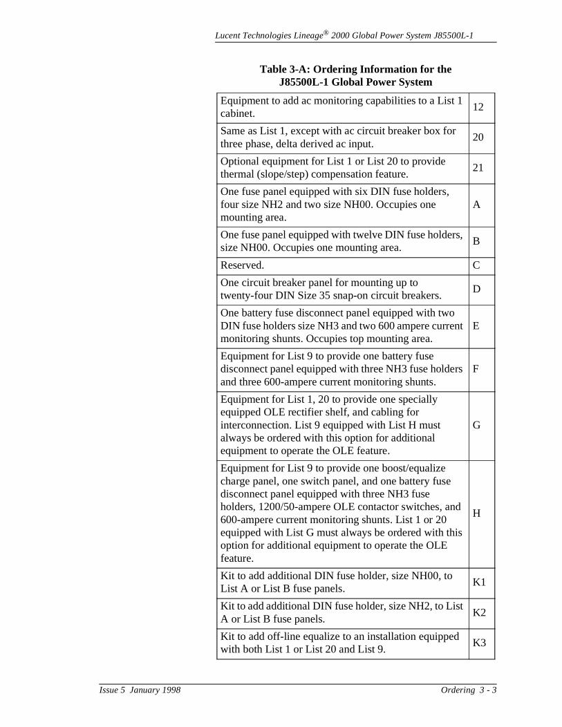
Lucent Technologies Lineage® 2000 Global Power System J85500L-1
Equipment to add ac monitoring capabilities to a List 1 cabinet.
12
Same as List 1, except with ac circuit breaker box for three phase, delta derived ac input.
20
Optional equipment for List 1 or List 20 to provide thermal (slope/step) compensation feature.
21
One fuse panel equipped with six DIN fuse holders, four size NH2 and two size NH00. Occupies one mounting area.
A
One fuse panel equipped with twelve DIN fuse holders, size NH00. Occupies one mounting area.
B
Reserved. C
One circuit breaker panel for mounting up to twenty-four DIN Size 35 snap-on circuit breakers.
D
One battery fuse disconnect panel equipped with two DIN fuse holders size NH3 and two 600 ampere current monitoring shunts. Occupies top mounting area.
E
Equipment for List 9 to provide one battery fuse disconnect panel equipped with three NH3 fuse holders and three 600-ampere current monitoring shunts.
F
Equipment for List 1, 20 to provide one specially equipped OLE rectifier shelf, and cabling for interconnection. List 9 equipped with List H must always be ordered with this option for additional equipment to operate the OLE feature.
G
Equipment for List 9 to provide one boost/equalize charge panel, one switch panel, and one battery fuse disconnect panel equipped with three NH3 fuse holders, 1200/50-ampere OLE contactor switches, and 600-ampere current monitoring shunts. List 1 or 20 equipped with List G must always be ordered with this option for additional equipment to operate the OLE feature.
H
Kit to add additional DIN fuse holder, size NH00, to List A or List B fuse panels.
K1
Kit to add additional DIN fuse holder, size NH2, to List A or List B fuse panels.
K2
Kit to add off-line equalize to an installation equipped with both List 1 or List 20 and List 9.
K3
Table 3-A: Ordering Information for the J85500L-1 Global Power System
Issue 5 January 1998 Ordering 3 - 3

Lucent Technologies Lineage® 2000 Global Power System J85500L-1
f ion
is
Supplementary Components
Documentation This document (Select Code 167-790-047) is part of a set odocumentation developed to assist engineering and installatpersonnel. Additional product information includes the following:
Battery Plant
J85500L-1 Assembly and Ordering DrawingED-83130-30 AC Distribution DrawingED-83131-30 DC Distribution DrawingT-83167-30 Wiring DrawingSD-83167-01 Schematic Drawing
Supplementary information on the ECS controller, Lineage® 2000 SR series rectifier, and Rectifier Shelf Assembly (RSA)in the following documents.
ECS Controller
J85501D-2 Assembly DrawingSD-82669-02 Schematic Drawing167-790-033 Product Manual167-790-109 Optional Circuit Pack Product Manual
SR Series Rectifiers and Rectifier Shelf Assembly
J85702B-2 Assembly DrawingJ85702F-1 Assembly DrawingT-82668-30 Wiring DrawingSD-82668-01 Schematic Drawing167-790-117 Product Manual
Table 3-B: Supplementary Components
Description Comcode
Thermistor Kit, Paddles 847618048
Thermistor Kit, Rings 847618063
3 - 4 Ordering Issue 5 January 1998
Lucent Technologies Lineage® 2000 Global Power System J85500L-1
. nal
rea
in
ces.
d tor
.
to
s or
4 Safety
Safety Statements
Please read and follow all safety instructions and warnings before installing, maintaining, or repairing the power systemReference the individual module product manuals for additiosafety statements specific to the modules.
This document is intended to be grounded (earthed) in accordance with all applicable local codes.
Install only in restricted access areas (dedicated equipment rooms, equipment closets, or the like) in accordance with allapplicable local codes.
This equipment is to be used in controlled environments (an awhere the humidity is maintained at levels that cannot causecondensation on the equipment, the contaminating dust is controlled, and the steady-state ambient temperature is withthe range specified).
This equipment must not be installed over combustible surfa
For all installations, the appropriate connector is to be applieonly to the correct size conductor as specified by the connecmanufacturer using only the connector manufacturer's recommended tooling or tooling approved for that connector
If the proper connector for the country of installation is not provided, obtain appropriate connectors and follow manufacturer's and all local requirements for proper connections. All national and local rules and regulations arebe followed when making field connections.
Torque electrical connections to the values specified on labelin the product documentation.
Issue 5 January 1998 Safety 4 - 1
Lucent Technologies Lineage® 2000 Global Power System J85500L-1
e in he
s.
will
t be
ent
.5 ust
r e
Battery input cables must be dressed to avoid damage to thinsulation (caused by routing around sharp edges or routed areas where wires could get pinched) and undue stress on tconnectors.
The short circuit current capability of the battery input to thedistribution panel must not exceed 10,000 amperes.
AC branch circuits to this equipment must be protected witheither fuses or circuit breakers in accordance with local codeRefer to the equipment ratings to assure rating of equipment not exceed 80% of the value of the protector chosen.
An accessible ac disconnect/protection device to remove acpower from the equipment in the event of an emergency musprovided. This device must open all poles and be connectedtogether.
When connecting to 3-wire plus neutral supply systems, theneutral is to be reliably earthed at the supply; i.e., this equipmis not intended to be connected to IT supply systems.
Internal relays have contacts rated at no more than 60Vdc, 0amperes. Any external circuits connected to internal relays mbe limited to this rating.
Side and back covers must be installed over open areas afteinstallation or servicing. Front doors and covers must also bkept in place.
Warning Statements And Safety Symbols
This symbol identifies the need to refer to the equipment instructions for important information.
4 - 2 Safety Issue 5 January 1998
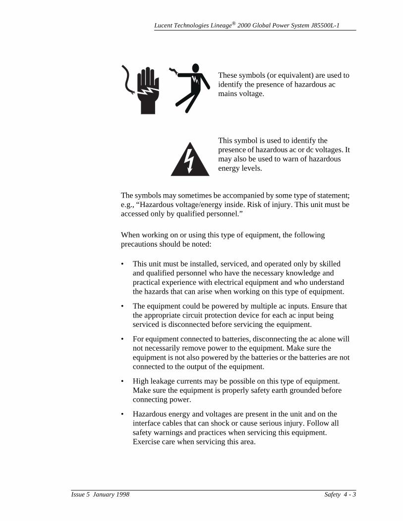
Lucent Technologies Lineage® 2000 Global Power System J85500L-1
It
ent; e
t.
at
ill
not
These symbols (or equivalent) are used toidentify the presence of hazardous ac mains voltage.
This symbol is used to identify the presence of hazardous ac or dc voltages. may also be used to warn of hazardous energy levels.
The symbols may sometimes be accompanied by some type of stateme.g., “Hazardous voltage/energy inside. Risk of injury. This unit must baccessed only by qualified personnel.”
When working on or using this type of equipment, the following precautions should be noted:
• This unit must be installed, serviced, and operated only by skilled and qualified personnel who have the necessary knowledge and practical experience with electrical equipment and who understandthe hazards that can arise when working on this type of equipmen
• The equipment could be powered by multiple ac inputs. Ensure ththe appropriate circuit protection device for each ac input being serviced is disconnected before servicing the equipment.
• For equipment connected to batteries, disconnecting the ac alone wnot necessarily remove power to the equipment. Make sure the equipment is not also powered by the batteries or the batteries areconnected to the output of the equipment.
• High leakage currents may be possible on this type of equipment. Make sure the equipment is properly safety earth grounded beforeconnecting power.
• Hazardous energy and voltages are present in the unit and on theinterface cables that can shock or cause serious injury. Follow all safety warnings and practices when servicing this equipment. Exercise care when servicing this area.
Issue 5 January 1998 Safety 4 - 3
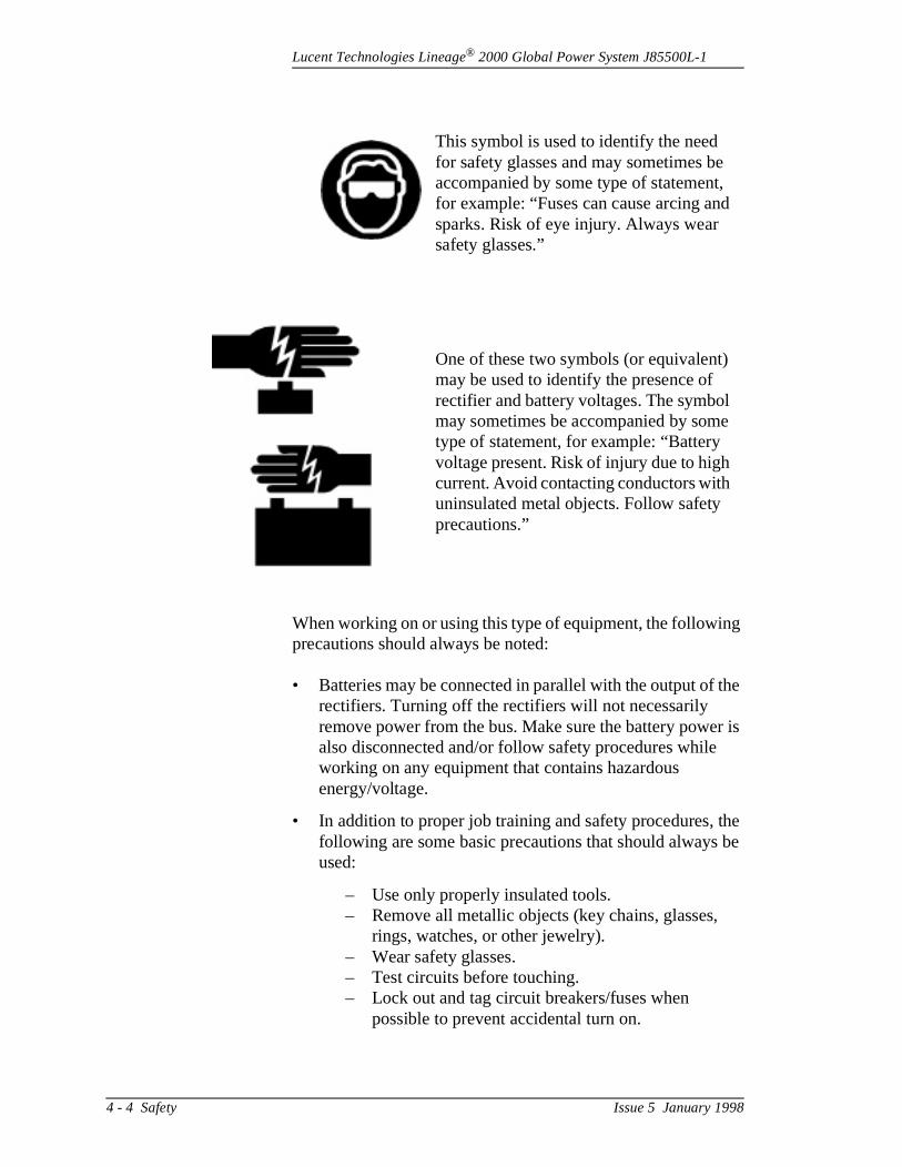
Lucent Technologies Lineage® 2000 Global Power System J85500L-1
g
he
r is
he be
When working on or using this type of equipment, the followinprecautions should always be noted:
• Batteries may be connected in parallel with the output of trectifiers. Turning off the rectifiers will not necessarily remove power from the bus. Make sure the battery powealso disconnected and/or follow safety procedures while working on any equipment that contains hazardous energy/voltage.
• In addition to proper job training and safety procedures, tfollowing are some basic precautions that should alwaysused:
– Use only properly insulated tools.– Remove all metallic objects (key chains, glasses,
rings, watches, or other jewelry).– Wear safety glasses. – Test circuits before touching.– Lock out and tag circuit breakers/fuses when
possible to prevent accidental turn on.
This symbol is used to identify the need for safety glasses and may sometimes beaccompanied by some type of statement,for example: “Fuses can cause arcing andsparks. Risk of eye injury. Always wear safety glasses.”
One of these two symbols (or equivalent) may be used to identify the presence of rectifier and battery voltages. The symbolmay sometimes be accompanied by sometype of statement, for example: “Battery voltage present. Risk of injury due to high current. Avoid contacting conductors with uninsulated metal objects. Follow safety precautions.”
4 - 4 Safety Issue 5 January 1998
Lucent Technologies Lineage® 2000 Global Power System J85500L-1
n e
id
– Be aware of potential hazards before servicing equipment.
– Identify exposed hazardous electrical potentials oconnectors, wiring, etc. (note the condition of thescircuits, especially wiring).
– Use care when removing or replacing covers; avocontacting circuits.
These symbols are used to identify the safety earth ground or bonding point for the equipment.
Issue 5 January 1998 Safety 4 - 5

Lucent Technologies Lineage® 2000 Global Power System J85500L-1
l to ts,
er st be gh o be t.
m,
t
5 Installation
General This section outlines a sequence for installation of the GlobaPower System. A suggested test sequence is also providedcheck the integrity of the installation effort. Upgrades, retrofiand replacement of equipment are also discussed.
To improve shipping and handling, the rectifiers and controllcircuit packs CP2 and CP3 are packaged separately and muplugged into the system during the installation process. Thounot discussed in this manual, the battery subsystem must alsassembled by the installer and connected to the battery plan
Installation Tools and Test Equipment
• Material handling equipment to unload cabinet at site, remove from shipping container, and set in final position [Minimum lifting capacity of 800 lb (363 kg)]
• Drill to bore holes for floor anchors (12 mm anchors provided)
• Cable racks and associated hardware• Input and output cables and terminal lugs• Common electrician’s hand tools, including jeweler’s
screwdriver, electrical tape, wire cutters, and strippers• Insulated 5 mm Allen wrench key (provided with cabinet)• 1/2-inch Allen wrench (provided with cabinet)• Proper crimping tools and dies for connectors• Common mechanic’s hand tools, including flat blade
screwdriver, socket and torque wrenches for 8 mm, 13 m17 mm, and 19 mm bolts, and a crowbar for uncrating
• M8 and M10 bolts, washers, and lockwashers to connecbattery leads and load return leads to the plant busbars
• DMM (Digital Multimeter) with at least 0.05% accuracy onthe dc scale
• Load Box - 50 amperes at 48 volts
Issue 5 January 1998 Installation 5 - 1
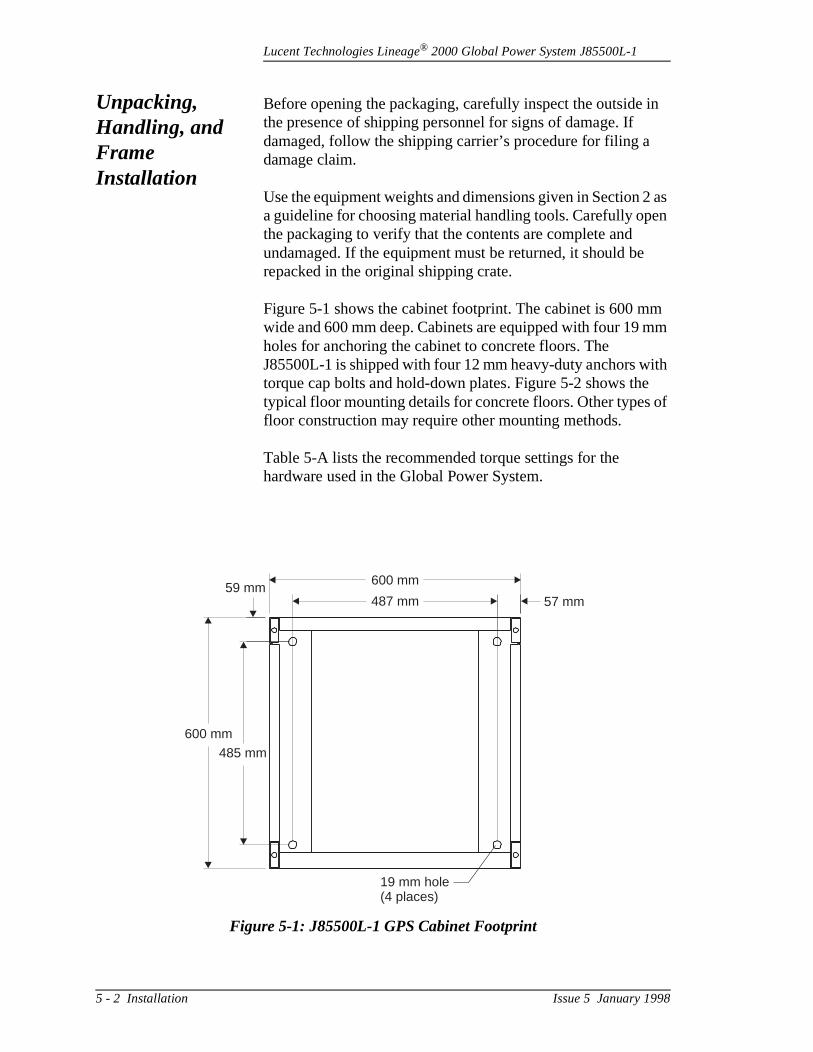
Lucent Technologies Lineage® 2000 Global Power System J85500L-1
in
2 as en
m mm
ith
of
Unpacking, Handling, and Frame Installation
Before opening the packaging, carefully inspect the outside the presence of shipping personnel for signs of damage. If damaged, follow the shipping carrier’s procedure for filing a damage claim.
Use the equipment weights and dimensions given in Section a guideline for choosing material handling tools. Carefully opthe packaging to verify that the contents are complete and undamaged. If the equipment must be returned, it should berepacked in the original shipping crate.
Figure 5-1 shows the cabinet footprint. The cabinet is 600 mwide and 600 mm deep. Cabinets are equipped with four 19 holes for anchoring the cabinet to concrete floors. The J85500L-1 is shipped with four 12 mm heavy-duty anchors wtorque cap bolts and hold-down plates. Figure 5-2 shows thetypical floor mounting details for concrete floors. Other typesfloor construction may require other mounting methods.
Table 5-A lists the recommended torque settings for the hardware used in the Global Power System.
Figure 5-1: J85500L-1 GPS Cabinet Footprint
57 mm
600 mm
600 mm
487 mm
485 mm
59 mm
19 mm hole(4 places)
5 - 2 Installation Issue 5 January 1998
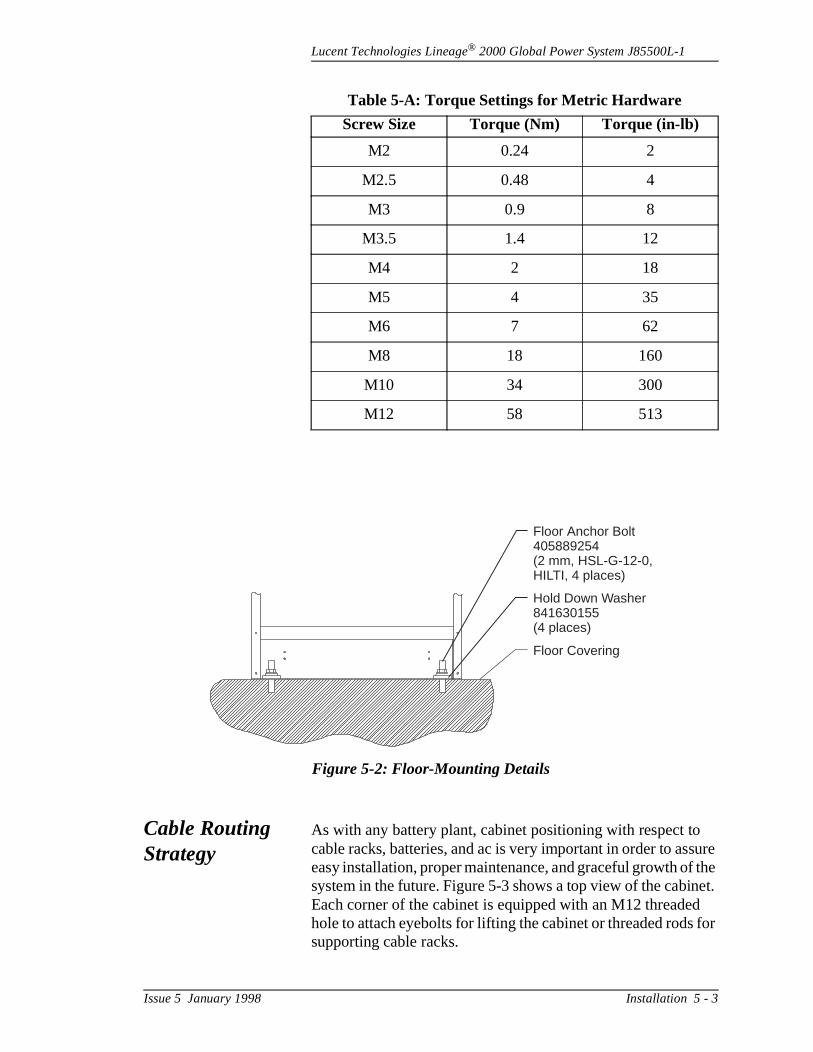
Lucent Technologies Lineage® 2000 Global Power System J85500L-1
sure the et.
d for
Cable Routing Strategy
As with any battery plant, cabinet positioning with respect tocable racks, batteries, and ac is very important in order to aseasy installation, proper maintenance, and graceful growth ofsystem in the future. Figure 5-3 shows a top view of the cabinEach corner of the cabinet is equipped with an M12 threadehole to attach eyebolts for lifting the cabinet or threaded rodssupporting cable racks.
Table 5-A: Torque Settings for Metric Hardware
Screw Size Torque (Nm) Torque (in-lb)
M2 0.24 2
M2.5 0.48 4
M3 0.9 8
M3.5 1.4 12
M4 2 18
M5 4 35
M6 7 62
M8 18 160
M10 34 300
M12 58 513
Figure 5-2: Floor-Mounting Details
Floor Anchor Bolt405889254(2 mm, HSL-G-12-0,HILTI, 4 places)
Hold Down Washer841630155(4 places)
Floor Covering
Issue 5 January 1998 Installation 5 - 3
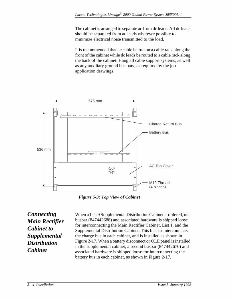
Lucent Technologies Lineage® 2000 Global Power System J85500L-1
ads
the ong well
ne ose e ts lled and e
The cabinet is arranged to separate ac from dc leads. All dc leshould be separated from ac leads wherever possible to minimize electrical noise transmitted to the load.
It is recommended that ac cable be run on a cable rack alongfront of the cabinet while dc leads be routed to a cable rack althe back of the cabinet. Hang all cable support systems, as as any auxiliary ground bus bars, as required by the job application drawings.
Connecting Main Rectifier Cabinet to Supplemental Distribution Cabinet
When a List 9 Supplemental Distribution Cabinet is ordered, obusbar (847442688) and associated hardware is shipped lofor interconnecting the Main Rectifier Cabinet, List 1, and thSupplemental Distribution Cabinet. This busbar interconnecthe charge bus in each cabinet, and is installed as shown inFigure 2-17. When a battery disconnect or OLE panel is instain the supplemental cabinet, a second busbar (847442670) associated hardware is shipped loose for interconnecting thbattery bus in each cabinet, as shown in Figure 2-17.
Figure 5-3: Top View of Cabinet
575 mm
536 mm
Charge Return Bus
Battery Bus
AC Top Cover
M12 Thread(4 places)
5 - 4 Installation Issue 5 January 1998

Lucent Technologies Lineage® 2000 Global Power System J85500L-1
s
f
g
r
h
d
d
Connecting AC to the Global Power System
The procedure for wiring ac to the Global Power System is afollows.
1. Open door of ac circuit breaker box located at the top othe cabinet.
2. Install conduit to top of ac circuit breaker box by removinthe proper size knockout. Top of box can be removed toease removal of knockout.
3. Run wires through conduit and into the ac circuit breakebox.
4. Terminate Earth Ground and Neutral (wye configurationonly) to appropriate distribution blocks using the 1/2-incAllen wrench furnished with the cabinet.
5. Terminate Lines 1, 2, and 3 to appropriate taps.
6. Check that all rectifier circuit breakers are turned off (down) before applying main ac power.
7. Turn main ac circuit breaker on.
8. Use an ac voltmeter to check that proper ac voltage is present.
9. Close door to ac circuit breaker box.
10. Proceed to paragraph “Installing a Rectifier.”
Warning
Hazardous ac voltage. Extreme caution should be exercisewhen performing this procedure.
Note
If system is equipped with List 12, AC Monitor Circuit Lines1, 2, and 3 must be run through transformers TA1, TA2, anTA3, respectively, located behind the circuit breakers. See paragraph “AC Monitoring Setup and Controller Programming.”
Issue 5 January 1998 Installation 5 - 5
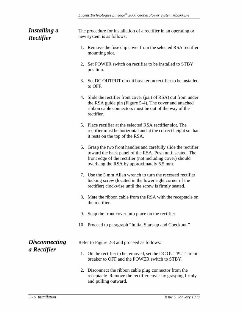
Lucent Technologies Lineage® 2000 Global Power System J85500L-1
ier
d
r
hat
ier e
r
on
uit
y
Installing a Rectifier
The procedure for installation of a rectifier in an operating ornew system is as follows:
1. Remove the fuse clip cover from the selected RSA rectifmounting slot.
2. Set POWER switch on rectifier to be installed to STBY position.
3. Set DC OUTPUT circuit breaker on rectifier to be installeto OFF.
4. Slide the rectifier front cover (part of RSA) out from undethe RSA guide pin (Figure 5-4). The cover and attachedribbon cable connectors must be out of the way of the rectifier.
5. Place rectifier at the selected RSA rectifier slot. The rectifier must be horizontal and at the correct height so tit rests on the top of the RSA.
6. Grasp the two front handles and carefully slide the rectiftoward the back panel of the RSA. Push until seated. Thfront edge of the rectifier (not including cover) should overhang the RSA by approximately 6.5 mm.
7. Use the 5 mm Allen wrench to turn the recessed rectifielocking screw (located in the lower right corner of the rectifier) clockwise until the screw is firmly seated.
8. Mate the ribbon cable from the RSA with the receptacle the rectifier.
9. Snap the front cover into place on the rectifier.
10. Proceed to paragraph “Initial Start-up and Checkout.”
Disconnecting a Rectifier
Refer to Figure 2-3 and proceed as follows:
1. On the rectifier to be removed, set the DC OUTPUT circbreaker to OFF and the POWER switch to STBY.
2. Disconnect the ribbon cable plug connector from the receptacle. Remove the rectifier cover by grasping firmland pulling outward.
5 - 6 Installation Issue 5 January 1998
Lucent Technologies Lineage® 2000 Global Power System J85500L-1
w
m
ly st d.
ers n,
on
ell he
is
re
be ller
ob
3. Insert the 5 mm Allen wrench in the rectifier locking screopening. Turn the locking screw counterclockwise until the screw turns freely.
4. Grasp the front panel handles and slide/pull rectifier frothe RSA.
Initial Start-up and Checkout
This paragraph describes the testing procedure for both newinstalled or replacement rectifiers. The rectifier installation temust be performed after controller tests have been completeOccasional references will be made to tables and figures in Section 2.
ElectricalTesting for
Rectifiers
The following procedures can be used to verify that the rectifiare working either after initial installation, subsequent additioor replacement of a rectifier. For troubleshooting and diagnostics, refer to Section 6. Those unfamiliar with the function of rectifier controls and indicators should read Secti2.
BackgroundInformation
Voltage required to operate the indicators on the rectifier, as was some of the relays, is derived from the ac input voltage. Tac voltage is available to these circuits whenever ac serviceavailable to the rectifier.
Selection ofInternal Selective
High VoltageShutdown Level
The rectifier Internal Selective High Voltage Shutdown featuis disabled when a controller is present since the controller provides this feature. However, this voltage level should still set correctly to avoid false shutdowns in the event the contro
Note
Due to energy storage in the rectifier, the front panel LEDs will remain lit for approximately one minute after removal ofac voltage. No hazardous voltages exist on the rectifier terminals during this time.
DANGER
Before turning on any rectifier, be sure that the associated framework and cable rack are properly grounded per local jinstructions and code requirements.
Issue 5 January 1998 Installation 5 - 7

Lucent Technologies Lineage® 2000 Global Power System J85500L-1
el e to
on 5.
ier
e al o
to
bled
w y).
:
t
.
is removed for maintenance, repair, or replacement. This levshould be set at least 1.5 volts above the normal float voltagavoid false shutdowns. See Figure 2-6 for location of DIP switches. Set the DIP switches according to the table printedthe face of the rectifier. This table is reproduced in Figure 2-
Selection ofBackup High
VoltageShutdown Level
The backup high-voltage shutdown circuit protects the rectifand its loads in the event of a high-voltage condition. The rectifier shuts down when its output voltage exceeds a user-selected threshold programmed by DIP switches in therectifier. These DIP switches are set in the factory to shut threctifier down when output voltages reach 59.5 ±0.5 volts, atypical value for telecommunications rectifiers. Two additionDIP switch settings are provided to increase user flexibility. Treduce the HVSD threshold below the value typical of telecommunications rectifiers, set the DIP switches accordingFigure 2-5.
Enabling/Disabling of
Load Sharing
The load share feature of the rectifier can be enabled or disathrough DIP switch position 5 located on the front of the rectifier. Set it according to Figure 2-5. The factory setting isenabled.
Initial Power-upand Adjustment
Set the ac supply and rectifier controls as follows:
• Associated ac circuit breaker ON at the ac circuit breaker box at the top of the cabinet
• Rectifier POWER switch to STBY and DC OUTPUTcircuit breaker lever to OFF
1. Insure the controller is set for the rectifier to be enabledand in float mode (refer to paragraph “Controller and LoVoltage Disconnect Setup, Wiring, and Test” if necessar
2. Verify that only the following LEDs are lit on the rectifierPOWER STBY, CB OFF.
3. At the rectifier, set the POWER switch to ON. Verify thaonly the following LEDs are lit: POWER ON, CB OFF. Check that the OUTPUT CURRENT display reads 00.0
5 - 8 Installation Issue 5 January 1998
Lucent Technologies Lineage® 2000 Global Power System J85500L-1
n in ld r
F
ter nd
s
,
er
:
T en
4. Connect the DMM to the PLANT (+) and (-) test jacks othe rectifier. If batteries are present or if other rectifiers the plant are ON and adjusted properly, the meter shouread the proper plant voltage. If there are no batteries oother rectifiers ON, the meter should read zero.
5. Connect DMM to the RECT (+) and (-) test jacks. The meter reading represents the rectifier output voltage produced with the DC OUTPUT circuit breaker in the OFposition. (See Notes below.) Using a jeweler’s screwdriver, adjust the VOLTS ADJ - FL potentiometer until the desired plant voltage level is obtained. The mereading should match the value read at the PLANT (+) a(-) test jacks.
6. Repeat Steps 2-5 for all rectifiers to be put on line at thitime.
7. If the plant is not to be configured for equalize operationproceed to Step 16.
8. At the controller, put the rectifier in equalize mode. (Refto paragraph “Equalize Enable/Disable.”)
9. At the rectifier, verify that only the following LEDs are litPOWER ON, CB OFF, EQ. Check that the OUTPUT CURRENT display reads 00.0.
Note
If the LED’s status is not as specified, refer to Section 6 fortroubleshooting help.
Note
If plant voltage is present, the voltage appearing at the RECtest jacks is never less than 1.5V below the plant voltage, evwith the rectifier turned off. When adjusting the rectifier, it may take many turns before the voltage at the rectifier test jacks begins to change. At this time do not close the DC OUTPUT circuit breaker.
Issue 5 January 1998 Installation 5 - 9
Lucent Technologies Lineage® 2000 Global Power System J85500L-1
n in ld r
he
ter nd
ine
e
t,
or
T en
10. Connect the DMM to the PLANT (+) and (-) test jacks othe rectifier. If batteries are present or if other rectifiers the plant are ON and adjusted properly, the meter shouread the proper plant voltage. If there are no batteries oother rectifiers ON, the meter should read zero.
11. Connect the DMM to the RECT (+) and (-) test jacks. Tmeter reading represents the rectifier output voltage produced with the DC OUT circuit breaker in the OFF position. (See Note below.) Adjust the VOLTS ADJ - EQpotentiometer using a jeweler’s screwdriver until the desired plant equalize voltage level is obtained. The mereading should match the value read at the PLANT (+) a(-) test jacks.
12. Repeat Steps 9 through 11 for all rectifiers to be put on lat this time.
13. Set the DC OUTPUT circuit breaker on all rectifiers to bput on line to the ON position. Verify that the CB-OFF LED is extinguished. If the plant is delivering load currenverify that all on-line rectifiers are delivering current (if not, see Note below). In addition, for plants configured fload sharing, verify that the plant load is divided amongthe rectifiers within specifications (10% of rating) as indicated on the rectifier OUTPUT CURRENT display.
14. Verify that only the EQ and ON LEDs are lit on each rectifier put on line.
Note
If the LED’s status is not as specified, refer to Section 6 fortroubleshooting help.
Note
If plant voltage is present, the voltage appearing at the RECtest jacks is never less than 1.5V below the plant voltage, evwith the rectifier turned off. When adjusting the rectifier, it may take many turns before the voltage at the rectifier test jacks begins to change. At this time do not close the DC OUTPUT circuit breaker.
5 - 10 Installation Issue 5 January 1998
Lucent Technologies Lineage® 2000 Global Power System J85500L-1
e
g g,
n
be ith
on
t a
.”
15. Return the rectifiers to float mode by setting the appropriate controller switch.
16. Set the DC OUTPUT circuit breaker on all rectifiers to bput on line to the ON position. If the plant is delivering load current, verify that all on-line rectifiers are deliverincurrent. In addition, for plants configured for load sharinverify that the plant load is divided among the rectifiers within 10 amperes as indicated on the rectifier OUTPUTCURRENT display.
17. Verify that only the ON LED is lit on each rectifier put oline.
Performance Testing
When load sharing is disabled, it is perfectly normal for one rectifier to be fully loaded and another producing no current.However, the following tests can be done to insure that all rectifiers are capable of producing current. These tests mayperformed when the plant is in float or equalize mode and wthe rectifiers in or out of loadshare mode.
Note
• Because of the sharing of the dc bus between rectifiers an RSA, a rectifier’s RECT test points may read higher than the PLANT test points although the rectifier is not producing any current.
• In some operational instances, the OUTPUT CURRENTdisplay on a rectifier may read 00.0 amperes. This in nomalfunction condition. It signifies that another rectifier is taking all the load. Refer to paragraph “Full Load Testing
Note
If the LED’s status is not as specified, refer to Section 6 fortroubleshooting help.
Note
If the LED’s status is not as specified, refer to Section 6 fortroubleshooting help.
Issue 5 January 1998 Installation 5 - 11
Lucent Technologies Lineage® 2000 Global Power System J85500L-1
ed
n.
gs
CT
L
st
t l
n.
gs
T
d. ith o
No Load Testing(NL)
This test is typically done on rectifiers that have load share disabled. This test can be performed on a rectifier that is producing any output current.This test should not be performon a plant consisting of only one rectifier.
1. Press and hold the RECT TEST switch in the NL positio
2. Observe that the reading on the OUTPUT CURRENT display of the rectifier decreases in value and the readinon the other rectifiers increase.
3. If the rectifier’s current does not decrease when the RETEST switch is in the NL position, turn the applicable potentiometer (FL or EQ) fully counterclockwise. If the rectifier is still producing a disproportionate amount of current, press and hold the RECT TEST switch in the Nposition. If the rectifier’s current does not decrease, replace the rectifier according to procedures outlined inparagraphs “Installing a Rectifier and “Disconnecting a Rectifier.” If the rectifier’s current does decrease, readjuits output according to the procedures outlined in paragraph “Initial Start-up and Checkout.”
Full LoadTesting (FL)
This test can be performed on a rectifier producing no outpucurrent although the other rectifiers on line are producing fuloutput current. This test should not be performed on plants consisting of only one rectifier.
1. Press and hold the RECT TEST switch in the FL positio
2. Observe that the reading on the OUTPUT CURRENT display of the rectifier increases in value and the readinon the other rectifiers decrease.
3. If the rectifier’s current does not increase when the RECTEST switch is in the FL position, turn the applicable
Note
It is normal for rectifiers not in load share to share load veryunevenly; it is also possible that the rectifiers are misadjusteRectifiers not running in load share mode can be adjusted wthe circuit breaker closed. Rectifiers may also be adjusted sthat some carry the majority of the load with remaining unitsfunctioning as hot spares.
5 - 12 Installation Issue 5 January 1998
Lucent Technologies Lineage® 2000 Global Power System J85500L-1
T t
s
l
use
n
or
potentiometer (FL or EQ) fully clockwise. If the rectifier isstill producing no current, press and hold the RECT TESswitch in the FL position. If the rectifier’s current does noincrease, replace the rectifier according to procedures outlined in paragraphs “Installing a Rectifier” and “Disconnecting a Rectifier.” If the rectifier’s current doesdecrease, readjust its output according to the procedureoutlined in paragraph “Initial Start-up and Checkout.”
Lamp Test The following test may be used to determine if all front paneLEDs and the display are functioning properly.
1. Place the rectifier in the STBY mode.
2. Press the NL/FL switch in either direction.
3. While the NL/FL switch is pressed, all front panel LEDsshould be illuminated and the meter should light and display -1888.
Adding an RSA to an Operating Plant
DANGER
Hazardous dc currents are present. These currents may caserious burns or death. To minimize risk:
1. Only persons trained and experienced in the installatioof power equipment should perform this installation.
2. The tasks should be performed only in the sequence given.
3. Use insulated tools. Remove rings, watch, and other jewelry.
4. Before contacting any uninsulated conductor surfaces,always use a voltmeter to ensure that either no voltagethe expected voltage is present.
Issue 5 January 1998 Installation 5 - 13
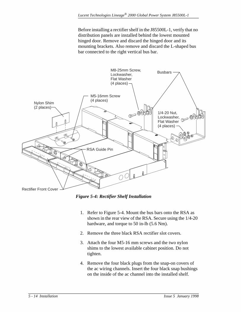
Lucent Technologies Lineage® 2000 Global Power System J85500L-1
o
us
s 20
f gs
Re
Before installing a rectifier shelf in the J85500L-1, verify that ndistribution panels are installed behind the lowest mounted hinged door. Remove and discard the hinged door and its mounting brackets. Also remove and discard the L-shaped bbar connected to the right vertical bus bar.
1. Refer to Figure 5-4. Mount the bus bars onto the RSA ashown in the rear view of the RSA. Secure using the 1/4-hardware, and torque to 50 in-lb (5.6 Nm).
2. Remove the three black RSA rectifier slot covers.
3. Attach the four M5-16 mm screws and the two nylon shims to the lowest available cabinet position. Do not tighten.
4. Remove the four black plugs from the snap-on covers othe ac wiring channels. Insert the four black snap bushinon the inside of the ac channel into the installed shelf.
Figure 5-4: Rectifier Shelf Installation
Busbars
Nylon Shim(2 places)
M5-16mm Screw(4 places)
1/4-20 Nut,Lockwasher,Flat Washer(4 places)
M8-25mm Screw,Lockwasher,Flat Washer(4 places)
ctifier Front Cover
RSA Guide Pin
5 - 14 Installation Issue 5 January 1998

Lucent Technologies Lineage® 2000 Global Power System J85500L-1
tact
rs ).
t or
t
te
:
e e
o
5. Place the RSA in the cabinet, above the four mounting screws and lower into position. The shims should be positioned between the rectifier and the cabinet.
6. Push the RSA back so that the RSA bus bars make conwith the cabinet bus bars at the back of the cabinet.
7. Secure the RSA bus bars to the vertical cabinet bus bausing M8-25 mm hardware. Torque to 160 in-lb (18 Nm
8. Secure the four M5-16 mm screws using a small sockewrench. Torque to 35 in-lb (4 Nm).
9. The J85500L-1 is factory wired with ribbon cables from the controller to each RSA slot. Locate and connect thecable to the RSA interface connector located on the righrear of the RSA.
10. The rectifier positions should be numbered in the J85500L-1 from right to left and from bottom to top to correspond to the locations assigned to rectifiers by thecontroller software. See Figure 5-5. Apply the appropriarectifier labels to the face of the rectifier front cover.
11. Remove the snap-on covers of the left and right ac channels from the installed shelf up to the ac box.
12. Verify that all unused ac circuit breakers are in the open(down) position.
13. The 847001195 cable assembly includes the wiring required to connect ac to the shelf. Wiring is 10 gauge (2.5 mm2) and color coded for easy reference as follows
Earth Ground Green/YellowNeutral BlueLine 1 BrownLine 2 BlackLine 3 Black/White
14. Route wiring for rectifier positions 7, 10, and 11 down thright channel and rectifier positions 8, 9, and 12 down thleft channel as required. Route ac wiring into rectifier shelves through the black snap bushings and connect tshelf as shown in Figure 2-16. AC wiring should be completed for all rectifier positions on the shelf.
Issue 5 January 1998 Installation 5 - 15
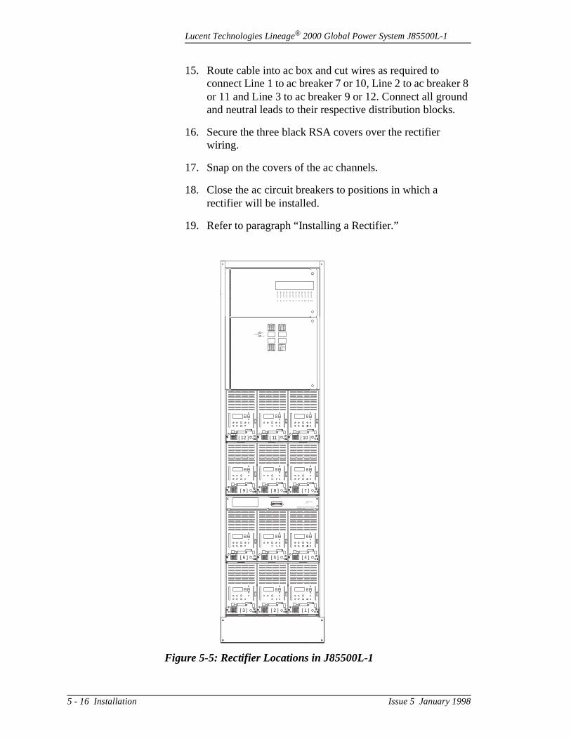
Lucent Technologies Lineage® 2000 Global Power System J85500L-1
r 8 nd
15. Route cable into ac box and cut wires as required to connect Line 1 to ac breaker 7 or 10, Line 2 to ac breakeor 11 and Line 3 to ac breaker 9 or 12. Connect all grouand neutral leads to their respective distribution blocks.
16. Secure the three black RSA covers over the rectifier wiring.
17. Snap on the covers of the ac channels.
18. Close the ac circuit breakers to positions in which a rectifier will be installed.
19. Refer to paragraph “Installing a Rectifier.”
Figure 5-5: Rectifier Locations in J85500L-1
RECT
1
RECT
2
RECT
3
RECT
4
RECT
5
RECT
6
RECT
7
RECT
8
RECT
9
RECT
10
RECT
11
RECT
12
LVD/R
LOAD
FAIL
OPEN
RECT
1
METER
CP2&3
CP1
CP1
RB
ABS
BAT
PWR
RECT
7
RECT
2
RECT
8
RECT
3
RECT
9
RECT
4
RECT
10
RECT
5
RECT
11
RECT
6
RECT
12
SPAREFUSES
1 1/3A
1 1/3A
1 1/3A
5A MAX
2A
[ 12 ]
[ 9 ]
[ 6 ]
[ 3 ]
[ 11 ]
[ 8 ]
[ 5 ]
[ 2 ]
[ 10 ]
[ 7 ]
[ 4 ]
[ 1 ]
LINEAGE 2000ECS
CONTAINSSTATIC SENSITIVE DEVICESUSE WRIST STRAP
5 - 16 Installation Issue 5 January 1998
Lucent Technologies Lineage® 2000 Global Power System J85500L-1
be re
t to
et ill ult t
rs
s.
Controller and Low Voltage Disconnect Setup, Wiring, and Test
Hardware Setup
There are jumper straps located on the backplane, the 113BControl Unit (CP1), and the LVD/Fuse Board (CP5) that mustset properly before powering the controller. These jumpers aset at the factory with proper settings for the Global Power System. Please note that all jumpers are numbered from righleft.
In addition to the jumpers, several DIP switches should be sbefore applying power. Incorrect switch settings, however, wnot damage the unit. Table 5-B summarizes the factory defasettings for user selectable options. Open the controller fronpanel and pull out the drawer.
Caution
Circuit packs can be damaged by static electricity. Operatoshould always wear a grounded wrist strap plugged into thecontroller front panel when touching or handling circuit packs.
Caution
Applying power to the controller when jumper straps are improperly arranged may damage the controller circuit pack
Issue 5 January 1998 Installation 5 - 17
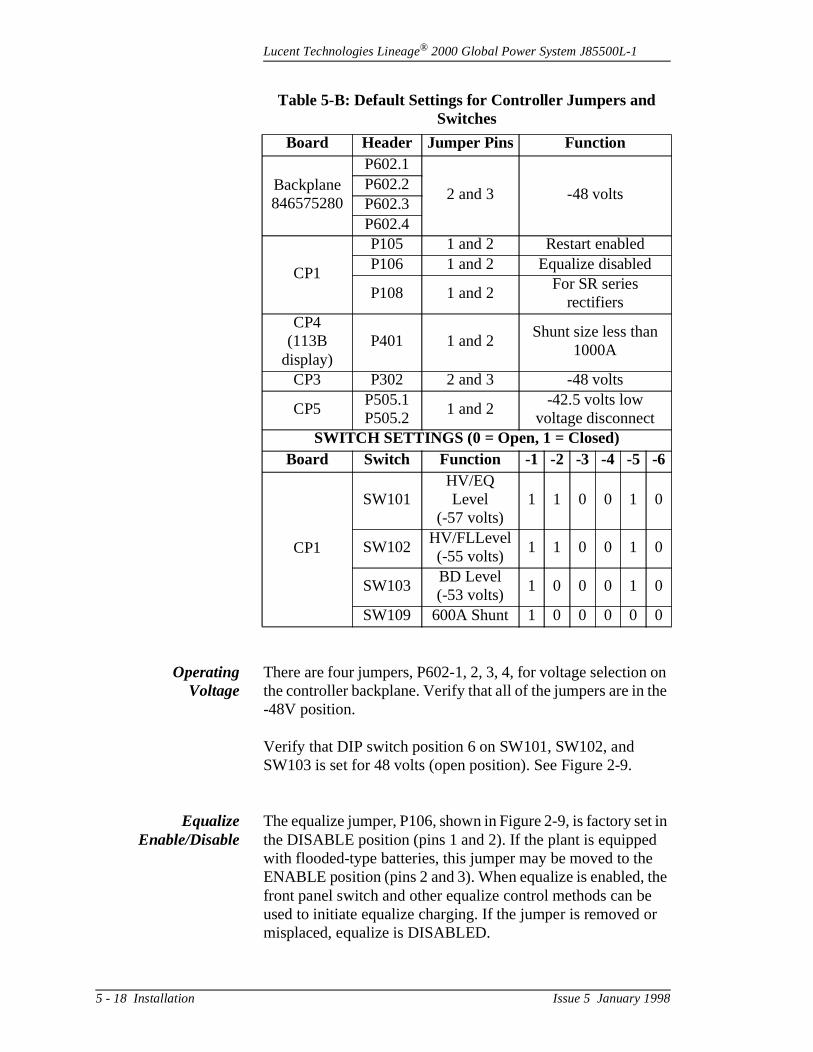
Lucent Technologies Lineage® 2000 Global Power System J85500L-1
on he
t in
the e r
OperatingVoltage
There are four jumpers, P602-1, 2, 3, 4, for voltage selectionthe controller backplane. Verify that all of the jumpers are in t-48V position.
Verify that DIP switch position 6 on SW101, SW102, and SW103 is set for 48 volts (open position). See Figure 2-9.
EqualizeEnable/Disable
The equalize jumper, P106, shown in Figure 2-9, is factory sethe DISABLE position (pins 1 and 2). If the plant is equippedwith flooded-type batteries, this jumper may be moved to theENABLE position (pins 2 and 3). When equalize is enabled, front panel switch and other equalize control methods can bused to initiate equalize charging. If the jumper is removed omisplaced, equalize is DISABLED.
Table 5-B: Default Settings for Controller Jumpers and Switches
Board Header Jumper Pins Function
Backplane846575280
P602.1
2 and 3 -48 voltsP602.2P602.3P602.4
CP1
P105 1 and 2 Restart enabledP106 1 and 2 Equalize disabled
P108 1 and 2For SR series
rectifiersCP4
(113B display)
P401 1 and 2Shunt size less than
1000A
CP3 P302 2 and 3 -48 volts
CP5P505.1P505.2
1 and 2-42.5 volts low
voltage disconnectSWITCH SETTINGS (0 = Open, 1 = Closed)
Board Switch Function -1 -2 -3 -4 -5 -6
CP1
SW101HV/EQ Level
(-57 volts)1 1 0 0 1 0
SW102HV/FLLevel(-55 volts)
1 1 0 0 1 0
SW103BD Level(-53 volts)
1 0 0 0 1 0
SW109 600A Shunt 1 0 0 0 0 0
5 - 18 Installation Issue 5 January 1998
Lucent Technologies Lineage® 2000 Global Power System J85500L-1
on ller For be
rent ere ale. the nd
ch er ely
is ”).
olts al ed ing
AutomaticRestart
Enable/Disable
The restart jumper, P105, is factory set in the ENABLE positi(pins 1 and 2). See Figure 2-9. This setting allows the controto attempt to restart rectifiers after a high voltage shutdown. one rectifier plant without battery reserve, the jumper shouldmoved to the DISABLE position (pins 2 and 3). Manual intervention will be required to restart the rectifier in such anapplication.
Ammeter Scale DIP switch SW109 is used to select the scale for the plant curmeter. The Global Power System is equipped with a 600-ampplant shunt and the controller preset to the proper ammeter scUse the label on the CP1 cover plate or Figure 2-10 to checkDIP switch settings versus the plant shunt rating. Verify thatposition 1 on SW109 is closed and that positions 2, 3, 4, 5, a6 are open.
Battery onDischargeThreshold
The voltage threshold for the BD alarms is set with DIP switSW103. (See Figure 2-9.) Refer to the label on the CP1 covplate or Figure 2-10 for the DIP switch setting for the desiredalarm threshold. The recommended threshold is approximat1.0 volt below the float voltage for nominal 48-volt plants.
High VoltageShutdown
Thresholds
The controller is equipped with two separate high voltage shutdown thresholds. The first is used during normal float operation. The second threshold is used when the plant is inequalize mode. The float shutdown is set with DIP switch SW102 on CP1. (See Figure 2-9.) The equalize shutdown iscontrolled by settings on DIP switch SW101 on CP1. The equalize shutdown level does not need to be set if equalize hardware disabled (see paragraph “Equalize Enable/DisableThe recommended shutdown levels are approximately 1.0 vabove operating voltage for nominal 48-volt plants. The actuoperating voltages in float and equalize modes are determinby the battery manufacturer’s recommendations and by anyrestrictions imposed by the load equipment. The factory settis -57 volts.
Caution
If the P105 jumper is removed or lost, the automatic restartfunction is DISABLED.
Issue 5 January 1998 Installation 5 - 19

Lucent Technologies Lineage® 2000 Global Power System J85500L-1
be ross
es
re. he
05.2 .5
er
all
4)
t
Rectifier RestartGroup Isolation
The Global Power System is equipped with all SR-series rectifiers, and the controller’s two restart signals should not isolated from each other. Jumper P108 should be placed acpins 1 & 2.
Low Voltage Disconnect Threshold (Optional)
The LVD/Fuse Board (CP5), illustrated in Figure 2-12, providboth controller power fusing and the low voltage battery disconnect/reconnect function. The latter is an optional featuIf the plant is not equipped with an LVD contactor as part of tplant distribution (List 2), the disconnect feature of the LVD/Fuse Board is not relevant. If the plant is equipped withlow voltage disconnect/reconnect, the disconnect voltage threshold must be selected by placing jumpers J505.1 and J5across pins 1 and 2 for 42.5 ±0.5 volts or pins 2 and 3 for 40±0.5 volts. The disconnect voltage is factory set at 42.5 ±0.5volts.
Basic Controller Wiring (CP1)
Each circuit pack in the controller may require connection tosystems outside the power plant or to other parts of the powsystem. The user must provide these connections. This paragraph addresses the wiring of the CP1 controller circuitpack.
The installer wiring associated with the basic controller is connected to four removable terminal blocks on the 113B Control Unit. The types of signals on these terminal blocks finto four categories:
• Alarm Outputs (BD, HV, ACF, LV, MJF, MNF, PMJs, andPMNs)
• Alarm Inputs (RMJ, RMN, and OS)• Control Inputs (TEQ, TEL, TF/ER, and TRs)• Miscellaneous Outputs (ABS and DG)
Three of the four terminal blocks (TB102, TB103, and TB10are assigned to the various office alarm outputs from the
Caution
If jumper P108 is removed or lost, the restart signals are isolated. In this configuration all SR-series rectifiers may noself-restart after HV shutdown.
5 - 20 Installation Issue 5 January 1998
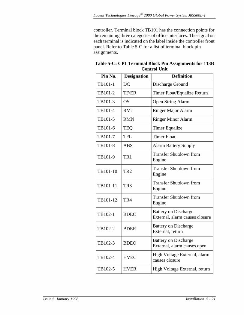
Lucent Technologies Lineage® 2000 Global Power System J85500L-1
or l on nt
controller. Terminal block TB101 has the connection points fthe remaining three categories of office interfaces. The signaeach terminal is indicated on the label inside the controller fropanel. Refer to Table 5-C for a list of terminal block pin assignments.
Table 5-C: CP1 Terminal Block Pin Assignments for 113B Control Unit
Pin No. Designation Definition
TB101-1 DC Discharge Ground
TB101-2 TF/ER Timer Float/Equalize Return
TB101-3 OS Open String Alarm
TB101-4 RMJ Ringer Major Alarm
TB101-5 RMN Ringer Minor Alarm
TB101-6 TEQ Timer Equalize
TB101-7 TFL Timer Float
TB101-8 ABS Alarm Battery Supply
TB101-9 TR1Transfer Shutdown from Engine
TB101-10 TR2Transfer Shutdown from Engine
TB101-11 TR3Transfer Shutdown from Engine
TB101-12 TR4Transfer Shutdown from Engine
TB102-1 BDECBattery on Discharge External, alarm causes closure
TB102-2 BDERBattery on Discharge External, return
TB102-3 BDEOBattery on Discharge External, alarm causes open
TB102-4 HVECHigh Voltage External, alarm causes closure
TB102-5 HVER High Voltage External, return
Issue 5 January 1998 Installation 5 - 21
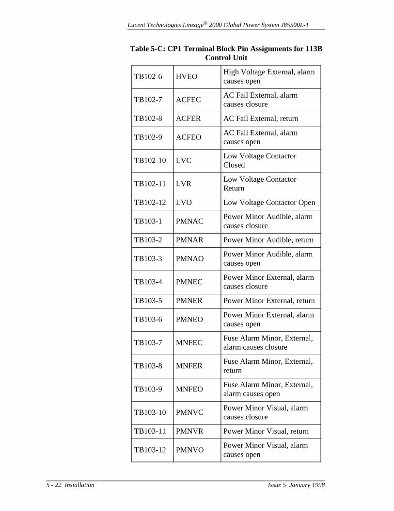
Lucent Technologies Lineage® 2000 Global Power System J85500L-1
TB102-6 HVEOHigh Voltage External, alarm causes open
TB102-7 ACFECAC Fail External, alarm causes closure
TB102-8 ACFER AC Fail External, return
TB102-9 ACFEOAC Fail External, alarm causes open
TB102-10 LVCLow Voltage Contactor Closed
TB102-11 LVRLow Voltage Contactor Return
TB102-12 LVO Low Voltage Contactor Open
TB103-1 PMNACPower Minor Audible, alarm causes closure
TB103-2 PMNAR Power Minor Audible, return
TB103-3 PMNAOPower Minor Audible, alarm causes open
TB103-4 PMNECPower Minor External, alarm causes closure
TB103-5 PMNER Power Minor External, return
TB103-6 PMNEOPower Minor External, alarm causes open
TB103-7 MNFECFuse Alarm Minor, External, alarm causes closure
TB103-8 MNFERFuse Alarm Minor, External, return
TB103-9 MNFEOFuse Alarm Minor, External, alarm causes open
TB103-10 PMNVCPower Minor Visual, alarm causes closure
TB103-11 PMNVR Power Minor Visual, return
TB103-12 PMNVOPower Minor Visual, alarm causes open
Table 5-C: CP1 Terminal Block Pin Assignments for 113B Control Unit
5 - 22 Installation Issue 5 January 1998
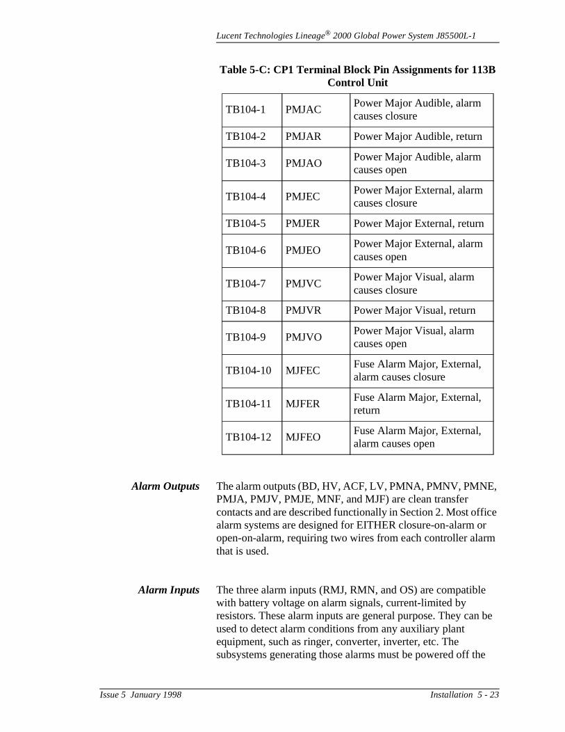
Lucent Technologies Lineage® 2000 Global Power System J85500L-1
ice r m
be
e
Alarm Outputs The alarm outputs (BD, HV, ACF, LV, PMNA, PMNV, PMNE,PMJA, PMJV, PMJE, MNF, and MJF) are clean transfer contacts and are described functionally in Section 2. Most offalarm systems are designed for EITHER closure-on-alarm oopen-on-alarm, requiring two wires from each controller alarthat is used.
Alarm Inputs The three alarm inputs (RMJ, RMN, and OS) are compatiblewith battery voltage on alarm signals, current-limited by resistors. These alarm inputs are general purpose. They canused to detect alarm conditions from any auxiliary plant equipment, such as ringer, converter, inverter, etc. The subsystems generating those alarms must be powered off th
TB104-1 PMJACPower Major Audible, alarm causes closure
TB104-2 PMJAR Power Major Audible, return
TB104-3 PMJAOPower Major Audible, alarm causes open
TB104-4 PMJECPower Major External, alarm causes closure
TB104-5 PMJER Power Major External, return
TB104-6 PMJEOPower Major External, alarm causes open
TB104-7 PMJVCPower Major Visual, alarm causes closure
TB104-8 PMJVR Power Major Visual, return
TB104-9 PMJVOPower Major Visual, alarm causes open
TB104-10 MJFECFuse Alarm Major, External, alarm causes closure
TB104-11 MJFERFuse Alarm Major, External, return
TB104-12 MJFEOFuse Alarm Major, External, alarm causes open
Table 5-C: CP1 Terminal Block Pin Assignments for 113B Control Unit
Issue 5 January 1998 Installation 5 - 23
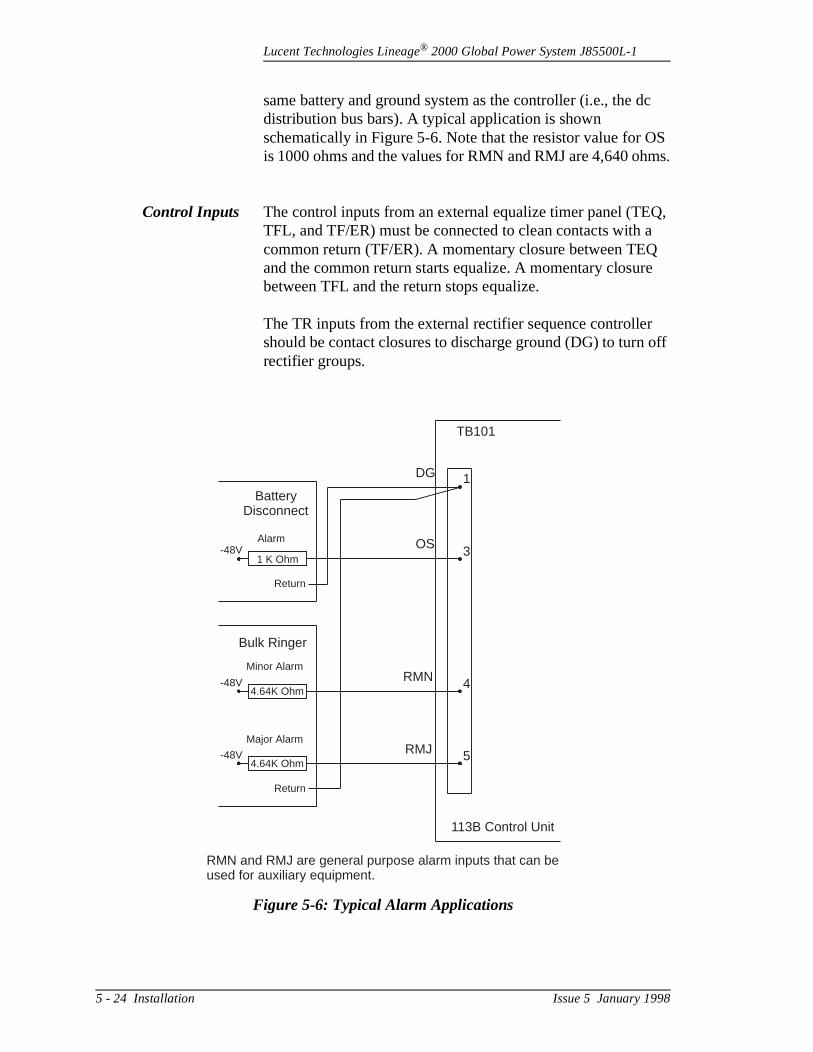
Lucent Technologies Lineage® 2000 Global Power System J85500L-1
c
S ms.
Q, a
e
r off
same battery and ground system as the controller (i.e., the ddistribution bus bars). A typical application is shown schematically in Figure 5-6. Note that the resistor value for Ois 1000 ohms and the values for RMN and RMJ are 4,640 oh
Control Inputs The control inputs from an external equalize timer panel (TETFL, and TF/ER) must be connected to clean contacts with common return (TF/ER). A momentary closure between TEQand the common return starts equalize. A momentary closurbetween TFL and the return stops equalize.
The TR inputs from the external rectifier sequence controlleshould be contact closures to discharge ground (DG) to turnrectifier groups.
Figure 5-6: Typical Alarm Applications
BatteryDisconnect
-48V
-48V
-48V
Alarm
Minor Alarm
Major Alarm
1 K Ohm
Return
Return
4.64K Ohm
4.64K Ohm
Bulk Ringer
DG
OS
RMN
RMJ
1
3
4
5
113B Control Unit
TB101
RMN and RMJ are general purpose alarm inputs that can beused for auxiliary equipment.
5 - 24 Installation Issue 5 January 1998

Lucent Technologies Lineage® 2000 Global Power System J85500L-1
e
ire ped
d.
the
s a
r l e
e.
e
), he e
f nd,
o
MiscellaneousOutputs
The miscellaneous signals are basically power (ABS) and ground (DG) to drive the office alarm system and some of thcontrol inputs to the controller.
The terminal blocks accept 22- to 24-gauge stranded wire. Wterminals are not used. The wire ends are stripped and clamdirectly in the terminal blocks. Multiconductor 24-gauge jacketed cable or 22-gauge twisted pair wire is recommende
1. Select the desired alarms and other signals. Determinetotal number of wires to be connected to the terminal blocks.
2. Select the configurations of cable and/or twisted pairs based on the number of signals that are to be directed agroup to different locations in the office.
3. Route the total wire bundle for CP1 through the openingon the left side of the chassis.
4. Allow for slack in the cable loop outside of the controlleso that the controller drawer will slide out freely to its fulextent. Approximately 8 inches (200 mm) of cable will bneeded.
5. Strip back the cable jacket(s), if present, approximatelyeight inches (200 mm) so that the individual wires reachtheir terminal block positions with no tension on any wir
6. Tape the ends of all extra (spare) wires that are not to bconnected during the initial installation.
7. Strip the remaining wires approximately 1/4-inch (5 mminsert in their respective terminal positions, and tighten tterminal block screws. Terminal blocks may be removedfrom the control unit for this step, if desired. Note that thterminal blocks are each polarized differently and are therefore not interchangeable.
8. Slide the drawer in and out to ensure that the amount ocable slack is adequate. When the desired length is foutie off the cable bundle with the wire ties and tie anchorpoints provided with the controller.
9. Connect Alarm Battery Supply and Discharge Ground talarm contacts as required to power the office alarms.
Issue 5 January 1998 Installation 5 - 25
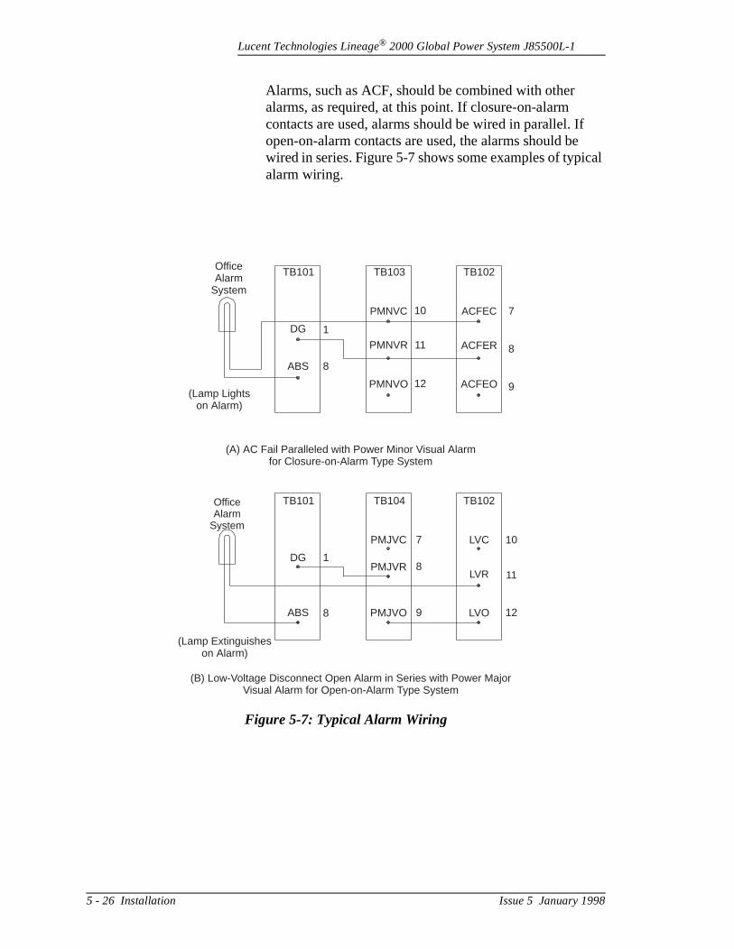
Lucent Technologies Lineage® 2000 Global Power System J85500L-1
cal
Alarms, such as ACF, should be combined with other alarms, as required, at this point. If closure-on-alarm contacts are used, alarms should be wired in parallel. Ifopen-on-alarm contacts are used, the alarms should bewired in series. Figure 5-7 shows some examples of typialarm wiring.
Figure 5-7: Typical Alarm Wiring
OfficeAlarm
System
OfficeAlarm
System
TB101
TB101
TB103
TB104
TB102
TB102
ACFEC
LVC
ACFER
LVR
ACFEO
LVO
PMNVO
PMJVO
PMNVR
PMJVR
PMNVC
PMJVC
DG
DG
ABS
ABS
(Lamp Lightson Alarm)
(Lamp Extinguisheson Alarm)
(A) AC Fail Paralleled with Power Minor Visual Alarmfor Closure-on-Alarm Type System
(B) Low-Voltage Disconnect Open Alarm in Series with Power MajorVisual Alarm for Open-on-Alarm Type System
8
8
1
1
10
7
11
8
12
9
9
12
8
11
7
10
5 - 26 Installation Issue 5 January 1998
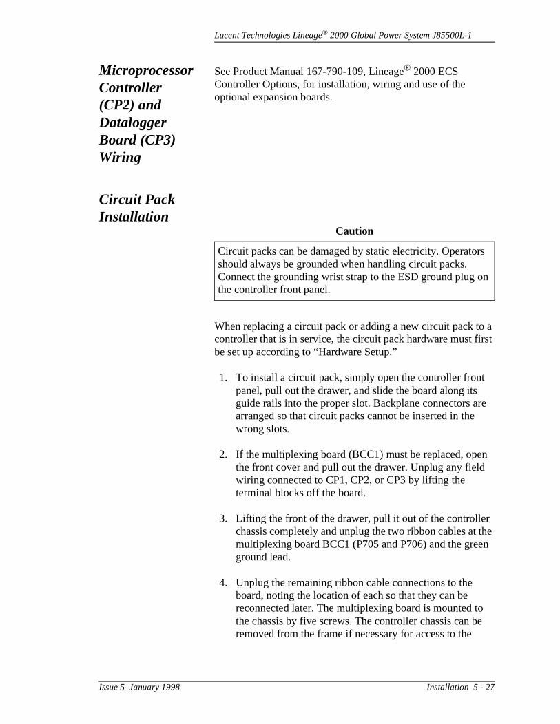
Lucent Technologies Lineage® 2000 Global Power System J85500L-1
a rst
re
n
the n
e
rs
n
Microprocessor Controller (CP2) and Datalogger Board (CP3) Wiring
See Product Manual 167-790-109, Lineage® 2000 ECS Controller Options, for installation, wiring and use of the optional expansion boards.
Circuit Pack Installation
When replacing a circuit pack or adding a new circuit pack tocontroller that is in service, the circuit pack hardware must fibe set up according to “Hardware Setup.”
1. To install a circuit pack, simply open the controller frontpanel, pull out the drawer, and slide the board along its guide rails into the proper slot. Backplane connectors aarranged so that circuit packs cannot be inserted in the wrong slots.
2. If the multiplexing board (BCC1) must be replaced, opethe front cover and pull out the drawer. Unplug any fieldwiring connected to CP1, CP2, or CP3 by lifting the terminal blocks off the board.
3. Lifting the front of the drawer, pull it out of the controllerchassis completely and unplug the two ribbon cables at multiplexing board BCC1 (P705 and P706) and the greeground lead.
4. Unplug the remaining ribbon cable connections to the board, noting the location of each so that they can be reconnected later. The multiplexing board is mounted tothe chassis by five screws. The controller chassis can bremoved from the frame if necessary for access to the
Caution
Circuit packs can be damaged by static electricity. Operatoshould always be grounded when handling circuit packs. Connect the grounding wrist strap to the ESD ground plug othe controller front panel.
Issue 5 January 1998 Installation 5 - 27

Lucent Technologies Lineage® 2000 Global Power System J85500L-1
and
ery ed ures ests
lip
ne
he y is ment
ted
board. Replace the board and reconnect ribbon cables ground wire as they were.
Acceptance Testing
The ECS controller is tested as a unit and as a part of a battplant system in the factory. This part of the manual is providfor those users who wish to repeat some of those test procedas part of the installation and turn-up process. Most of these tshould not be performed while the plant is powering active loads.
Test procedures:• Meter calibration• Battery on Discharge Alarm test*• Float/Equalize Control test• High Voltage Shutdown/Restart tests*• Fuse Alarm tests*• Remote ON/OFF (TR signal) test*• Ringer Alarm test*• Low Voltage Battery Disconnect test*
*These tests are not suitable for plants in service.
Test equipment required:• Dummy load - 50 amperes at 48 volts• Multimeter• Jeweler’s screwdriver• Flat-blade screwdriver• Blown fuse (Bussman GMT type)• Resistor, 4.64k ohm, 1 W minimum, 5%• Short length of 22- to 26-gauge wire
[4 inch (100 mm) maximum]• Power supply, adjustable 0-60 volts dc, 1 ampere, with c
leads.
Unless otherwise indicated in the test procedures, at least orectifier must be on line in batteryless plants.
Meter Calibration The controller voltmeter has an accuracy of 0.05% and a resolution of 1 digit. To accurately assess the calibration of tvoltmeter, an external meter with better than 0.05% accuracneeded. If such a meter is not available, only a rough assessof the controller meter calibration can be achieved. The controller meter is factory calibrated and should not be adjus
5 - 28 Installation Issue 5 January 1998
Lucent Technologies Lineage® 2000 Global Power System J85500L-1
TS
3.
nd
e e
in the field unless it is obviously outside the tolerance of theexternal meter.
If calibration is needed, set the meter select switch to the VOLposition. Adjust Potentiometer R407 on CP4 meter board.
Battery onDischarge Alarm
Test
1. Identify the BD threshold level set on DIP switch SW10
2. Turn off all rectifiers but one. Verify that the rectifier is delivering power and that only the NORM LED is lit on the controller.
3. Set the controller meter select switch to the VOLTS position and verify that the plant voltage is above the BDthreshold.
4. Adjust the dummy load to draw at least 5 amperes.
5. Adjust the rectifier output voltage down until the BD LEDon the controller lights. This should occur at the set threshold.
If Step 5 fails to produce the desired result, recheck theSW103 setting, raise the plant voltage back to normal, arepeat Step 5 by adjusting the rectifier voltage down slowly. Refer to Section 2 for voltage adjustment procedures.
6. With the BD alarm present, check with a multimeter or with the office alarm system (if connected) that the following alarms are present on the controller terminal blocks:
BDE, PMJE, PMJV, and PMJA
Note
This test cannot be performed on a live plant powering activloads. If possible, batteries should be disconnected from thplant to allow the plant voltage to be reduced easily.
Issue 5 January 1998 Installation 5 - 29

Lucent Technologies Lineage® 2000 Global Power System J85500L-1
he
ot
r
as
e
P1
e
f at
n
The terminal block positions are listed on a label inside tcontroller or see Table 5-C.
7. Slowly adjust the rectifier output voltage back up to normal, observing that the BD LED extinguishes at the correct voltage level within the specified tolerance. The green NORM LED should light when the BD LED goes out.
8. Check the office alarms on the CP1 terminal blocks to verify that no alarms are present.
Float/EqualizeControl Test
If the equalize function is disabled on CP1 or if the plant is nequipped with equalize-capable rectifiers, skip this test. Thedummy load is not required for this test.
1. Use the front panel switch to put the plant in equalize mode. Verify that the equalize LED lights on the controlleand that the rectifiers change to their equalize voltage settings. Readjust the equalize voltage of each rectifier,required. (Refer to Section 2 for voltage adjustment procedures.)
2. Return plant to float mode with the front panel switch. Thequalize LED should extinguish.
3. Momentarily short together pins 2 and 6 on TB101 on Cwith a piece of wire. This simulates an equalize initiationsignal from an external timer panel. Verify that the equalize LED lights and the rectifiers change to equalizmode.
4. Momentarily short pins 2 and 7 on TB101 with a piece owire. This should stop equalize and return the plant to flomode.
High VoltageShutdown/Restart
Test
1. Identify the HV shutdown threshold for float operation oDIP switch SW102. For best results, rectifiers should beset to Non-Load Share mode.
2. Turn on all rectifiers and adjust the dummy load so thateach rectifier delivers more than 10% of its full load current.
5 - 30 Installation Issue 5 January 1998
Lucent Technologies Lineage® 2000 Global Power System J85500L-1
he
V ut
s
d
o
3. Set the controller meter to read VOLTS, and verify that tgreen NORM indicator is the only LED that is lit on the controller.
4. At any one rectifier, slowly adjust its output voltage up until it shuts down. This should occur at the specified Hshutdown threshold. Verify that the correct rectifier is shdown.
5. Note that the NORM LED goes out and the yellow RFALED lights on the controller. If enough rectifier capacity inot still available to maintain the load, the red BD LED may also light.
6. Within ten (10) seconds of rectifier shutdown, the controller should automatically restart all rectifiers. The RFA LED should extinguish and the NORM LED shouldcome on.
7. Since one rectifier is adjusted high, the controller shoulissue another shutdown signal when the plant voltage again reaches the HV shutdown threshold.
8. After the second shutdown, the controller should NOT automatically attempt to restart rectifiers.
9. With the rectifier(s) shut down, check the office alarm terminal blocks to verify that the following alarms are present:
PMNE, PMNA, and PMNV
If the BD LED is also lit, the following alarms should alsbe present on the terminal blocks:
BDE, PMJE, PMJA, and PMJV
Note
In batteryless plants, if all rectifiers are shut down the controller loses power and will attempt to restart rectifiers more than just once. The user should disable the automaticrestart function in batteryless plants with only one rectifier. (See paragraph “Automatic Restart Enable/Disable.”)
Issue 5 January 1998 Installation 5 - 31

Lucent Technologies Lineage® 2000 Global Power System J85500L-1
le
e.
ch
st
n
ld o
ode.
tch
nt. n in
e
10. Readjust the misadjusted rectifier output voltage back down and restart any failed rectifiers manually (i.e., toggthe on/off switch). Once all rectifiers are back on line, perform the fine adjustment of the rectifier output voltag(Refer to Section 2 for voltage adjustment procedures.)
11. Verify that only the NORM LED is lit on the controller. Reset the restart timer in the controller by pressing switSW104, shown in Figure 2-9. This will prevent the controller from ignoring any HV shutdown that might occur in the next four to six minutes.
12. If the Float/Equalize function is disabled on CP1, this teis complete. If Float/Equalize is enabled, proceed with Step 13.
13. Identify the HV shutdown threshold for equalize operatioon DIP switch SW101.
14. Use the front panel switch to put the plant in equalize mode and verify that the EQ LED lights. This LED shoustay lit through the end of the test. The NORM LED is alslit at this point.
15. Repeat Steps 2 through 11 with the plant in equalize m
16. Return the plant to float mode using the front panel swion the controller.
Fuse Alarm Tests These tests may be performed with or without load on the plaNotice that F501-F524 correspond to positions 1-24 as showFigure 2-13.
1. Locate the LVD/Fuse Board. Insert a blown fuse in placof F501. The MNF (Minor Fuse Alarm) LED on the controller front panel should light and the NORM LED should go out. With a multimeter, verify that the followingoffice alarms are present on the appropriate terminal blocks on CP1:
MNFE, PMNE, PMNA, and PMNV
2. Replace the blown fuse with a good fuse. The alarms should retire and the MNF LED extinguish.
5 - 32 Installation Issue 5 January 1998

Lucent Technologies Lineage® 2000 Global Power System J85500L-1
2
nd
519
d
r.
o
3. Repeat Steps 1 and 2 for all minor fuses, including F50through F509 and F513 through F518, on the LVD/FuseBoard.
4. Replace F510 with a blown fuse. The MJF (Major FuseAlarm) LED should light, and the NORM LED should goout. Check the terminal blocks for the following major alarms:
MJFE, PMJE, PMJA, and PMJV
5. Reinsert the good fuse, and note that the alarms retire athat LEDs return to normal.
6. Repeat Steps 4 and 5 for major fuses F511, F512, and Fthrough F521.
7. For plants equipped with Battery String Disconnect Breakers Only, the Open String (OS) Alarm is hardwiredfrom the controller terminal blocks to an auxiliary fuse alarm input on the LVD/Fuse Board. If OS is wired into the LVD/Fuse Board, turn one disconnect breaker off toverify that the desired MJF or MNF alarm and associatepower alarms are issued. Turn the breaker back on andnote that the alarms retire.
8. Repeat Step 7 for each battery string disconnect breake
Remote On/Off(TR Signal) Test
1. Attach one end of a piece of wire to Discharge Ground (DG) on pin 1 of TB101 on CP1. This wire will be used tground the TR input signals to simulate a Rectifier Sequence Controller or other remote on/off device for controlling rectifiers.
2. Touch the free end of the wire, in turn, to each of the TRinputs on the terminal block pins listed below.
Verify that the listed rectifier or rectifiers turn off. When the wire is removed, the rectifier(s) should restart automatically. Disconnect the lead from both ends whenfinished.
Issue 5 January 1998 Installation 5 - 33
Lucent Technologies Lineage® 2000 Global Power System J85500L-1
ne is
ard,
0
m
he
en
TB101 Pin # Rectifier(s)
TR1 9 1, 5, 9TR2 10 2, 6, 10TR3 11 3, 7, 11TR4 12 4, 8, 12
Bulk RingerAlarm Test
This test involves connecting a lead with plant voltage from opoint to another on the controller terminal blocks. Although thvoltage is protected by the ABS fuse on the external fuse bocare should be taken to avoid touching and damaging components or printed wiring on CP1.
1. Connect one end of a 4640 ohm resistor to the Ringer Major Alarm input (RMJ) on pin 4 of TB101. Bend the free end clear of any metal parts (e.g., the chassis).
2. Attach one end of a piece of wire to the Alarm Battery Supply (ABS) on pin 8 of TB101.
3. Touch the free end of the wire to the free end of the 464ohm resistor. The NORM LED on the controller front panel should go out. With a multimeter or the office alarsystem, if connected, verify that the following major alarms are issued:
PMJE, PMJA, and PMJV
4. Disconnect the lead from the resistor and note that the alarms retire and the NORM LED turns on.
5. Remove the resistor from TB101 pin and connect it to tRinger Minor Alarm input (RMN) on pin 5 of TB101.
6. Touch the wire to the free end of the resistor. Again, theNORM LED should extinguish and the following power minor alarms should appear on the controller terminal blocks or office alarm system:
PMNE, PMNA, and PMNV
7. Disconnect the lead and the resistor from both ends whfinished. Close the controller front panel.
5 - 34 Installation Issue 5 January 1998

Lucent Technologies Lineage® 2000 Global Power System J85500L-1
ect
of 5
e e
, red
d
t the
e
. If
Low VoltageBattery
Disconnect Test
If the plant is not equipped with a low voltage battery disconncontactor, skip this test.
1. Disconnect all battery strings from the plant bus bars.
2. Turn off all but one of the rectifiers.
3. Check the locations of the jumpers P505.1 and P505.2.Place both jumpers across pins 1 and 2 for a threshold 42.5 ±0.5V or across pins 2 and 3 for a threshold of 40.±0.5V.
4. Using the front panel VOLTS ADJ FL adjustment of the“on” rectifier, lower the rectifier’s output voltage until thecontactor opens. By monitoring the voltage shown on thcontroller’s display, verify that the contactor opens in thvoltage range selected by jumpers P505.1 and P505.2.
5. After the contactor opens, temporarily place a shorting strap from the battery bus to the plant charging bus (i.e.across the contacts of the contactor) and verify that the LVD/OPEN LED on the LVD/Fuse Board is lit. The strapis required because the red LVD/OPEN LED normally receives its power from the battery. Verify that the BD anMNF LEDs on the controller’s front panel are also lit.
6. Adjust the “on” rectifier’s output voltage up until the contactor operates. This should occur within 0.5V of where the contact opened. Verify that the MNF LED extinguishes.
7. Reconnect the batteries to the plant bus bars and adjus“on” rectifier to its proper float voltage. The BD LED should extinguish.
Note
As the power supply voltage decreases and approaches thdisconnect threshold, the yellow LVD FAIL LED may light. This is normal and indicates that one part of the LVD circuithas reached its threshold before the other redundant circuitthe yellow LED lights within the disconnect tolerance and then the contactor opens, also within the tolerance, the lowvoltage battery disconnect circuit is functioning normally.
Issue 5 January 1998 Installation 5 - 35
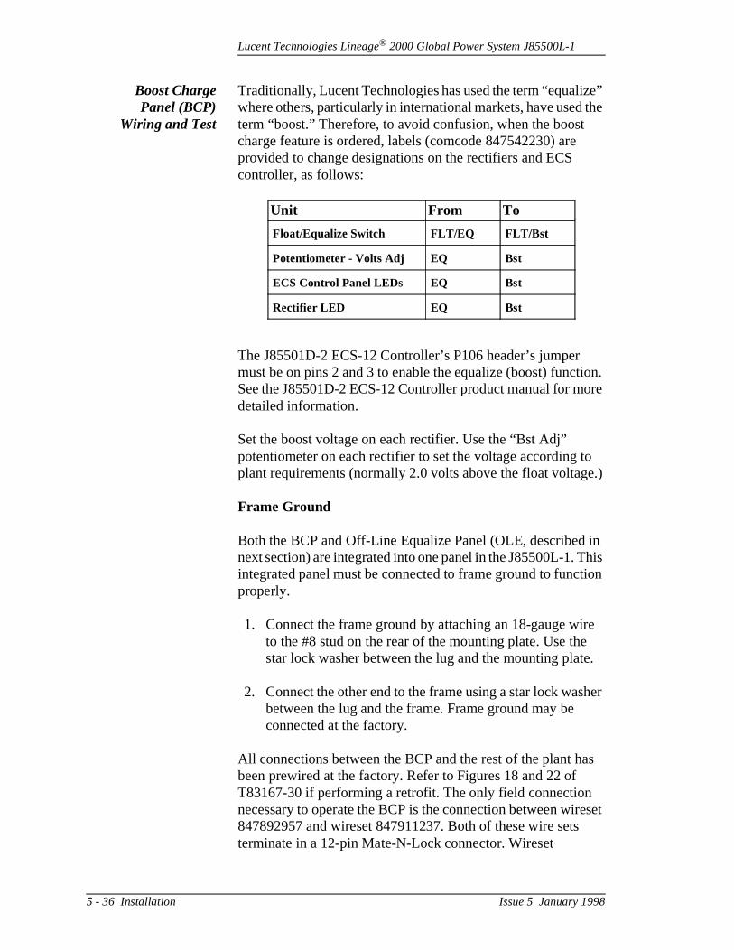
Lucent Technologies Lineage® 2000 Global Power System J85500L-1
e” the
ion. ore
to e.)
in his
tion
re
e.
her
as
eset
Boost ChargePanel (BCP)
Wiring and Test
Traditionally, Lucent Technologies has used the term “equalizwhere others, particularly in international markets, have usedterm “boost.” Therefore, to avoid confusion, when the boost charge feature is ordered, labels (comcode 847542230) areprovided to change designations on the rectifiers and ECS controller, as follows:
The J85501D-2 ECS-12 Controller’s P106 header’s jumper must be on pins 2 and 3 to enable the equalize (boost) functSee the J85501D-2 ECS-12 Controller product manual for mdetailed information.
Set the boost voltage on each rectifier. Use the “Bst Adj” potentiometer on each rectifier to set the voltage according plant requirements (normally 2.0 volts above the float voltag
Frame Ground
Both the BCP and Off-Line Equalize Panel (OLE, describednext section) are integrated into one panel in the J85500L-1. Tintegrated panel must be connected to frame ground to funcproperly.
1. Connect the frame ground by attaching an 18-gauge wito the #8 stud on the rear of the mounting plate. Use thestar lock washer between the lug and the mounting plat
2. Connect the other end to the frame using a star lock wasbetween the lug and the frame. Frame ground may be connected at the factory.
All connections between the BCP and the rest of the plant hbeen prewired at the factory. Refer to Figures 18 and 22 of T83167-30 if performing a retrofit. The only field connection necessary to operate the BCP is the connection between wir847892957 and wireset 847911237. Both of these wire setsterminate in a 12-pin Mate-N-Lock connector. Wireset
Unit From To
Float/Equalize Switch FLT/EQ FLT/Bst
Potentiometer - Volts Adj EQ Bst
ECS Control Panel LEDs EQ Bst
Rectifier LED EQ Bst
5 - 36 Installation Issue 5 January 1998
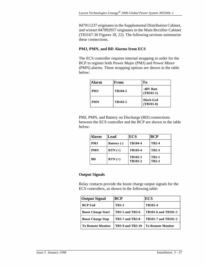
Lucent Technologies Lineage® 2000 Global Power System J85500L-1
et, net ize
e
le
ble
he
847911237 originates in the Supplemental Distribution Cabinand wireset 847892957 originates in the Main Rectifier Cabi(T83167-30 Figures 18, 22). The following sections summarthese connections.
PMJ, PMN, and BD Alarms from ECS
The ECS controller requires internal strapping in order for thBCP to register both Power Major (PMJ) and Power Minor (PMN) alarms. These strapping options are shown in the tabbelow:
PMJ, PMN, and Battery on Discharge (BD) connections between the ECS controller and the BCP are shown in the tabelow:
Output Signals
Relay contacts provide the boost charge output signals for tECS controllers, as shown in the following table:
Alarm From To
PMJ TB104-5-48V Batt (TB101-1)
PMN TB103-5Disch Grd (TB101-8)
Alarm Lead ECS BCP
PMJ Battery (-) TB104-4 TB2-4
PMN RTN (+) TB103-4 TB2-3
BD RTN (+)TB102-1TB102-2
TB2-1TB2-2
Output Signal BCP ECS
BCP Fail TB3-2 TB101-4
Boost Charge Start TB3-5 and TB3-6 TB101-6 and TB101-2
Boost Charge Stop TB3-7 and TB3-8 TB101-7 and TB101-2
To Remote Monitor TB3-9 and TB3-10 To Remote Monitor
Issue 5 January 1998 Installation 5 - 37
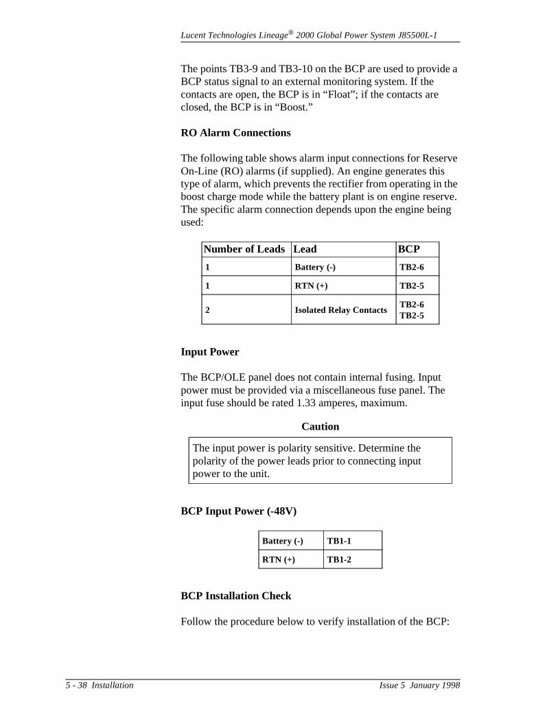
Lucent Technologies Lineage® 2000 Global Power System J85500L-1
e a
ve he rve. ng
e
The points TB3-9 and TB3-10 on the BCP are used to providBCP status signal to an external monitoring system. If the contacts are open, the BCP is in “Float”; if the contacts are closed, the BCP is in “Boost.”
RO Alarm Connections
The following table shows alarm input connections for ReserOn-Line (RO) alarms (if supplied). An engine generates thistype of alarm, which prevents the rectifier from operating in tboost charge mode while the battery plant is on engine reseThe specific alarm connection depends upon the engine beiused:
Input Power
The BCP/OLE panel does not contain internal fusing. Input power must be provided via a miscellaneous fuse panel. Thinput fuse should be rated 1.33 amperes, maximum.
BCP Input Power (-48V)
BCP Installation Check
Follow the procedure below to verify installation of the BCP:
Number of Leads Lead BCP
1 Battery (-) TB2-6
1 RTN (+) TB2-5
2 Isolated Relay ContactsTB2-6TB2-5
Caution
The input power is polarity sensitive. Determine the polarity of the power leads prior to connecting input power to the unit.
Battery (-) TB1-1
RTN (+) TB1-2
5 - 38 Installation Issue 5 January 1998

Lucent Technologies Lineage® 2000 Global Power System J85500L-1
8.
ld
e
l g to G25 and
fer
1. Set the OPTION switch SW1 to OFF, if the CONSTANTswitch is to be set.
2. Set the CONSTANT switch to a number between 1 and
3. Ensure that the “Boost Time” switch is in the MANUAL position.
4. Depress the RESET switch. Wait 10 seconds before continuing.
5. After 10 seconds, place the “Boost/Float” switch into the“boost” position and release. The following should happen:
a. The “Boost” (yellow) LED will light.
b. On the plant controller, the plant voltage reading shouincrease to the predetermined boost level.
6. Depress the “Boost/Float” switch to the FLOAT positionand release. The “Boost” LED should extinguish.
Note: If these things do not happen, review connections.
Off-LineEqualize Panel(OLE) Wiring
and Test
The off-line equalize feature for the J85500L-1 requires the following hardware, in addition to the OLE panel, in order tooperate correctly:
– J85702F-1 OLE Rectifier Shelf (always occupies the second position from the bottom)
– ED83131-30 G23 Battery Fuse Disconnect Panel– ED83131-30 G24 Battery Contactor Panel– ED83131-30 G25 Switch Panel
The J85702F-1 OLE Rectifier Shelf is a specially equipped rectifier shelf that allows the leftmost (position 6) rectifier to bswitched between the load bus and the equalize bus when abattery string is being equalized. The G23 Battery Fuse Disconnect Panel provides fused connections for the plant’sbattery strings, up to three. The G24 Battery Contactor Paneprovides three battery contactors that allow each battery strinbe switched between the load bus and the equalize bus. TheSwitch Panel provides the switches that actuate the rectifier battery contactors. All of this equipment is installed at the factory when a new plant is ordered with the OLE option. Re
Issue 5 January 1998 Installation 5 - 39
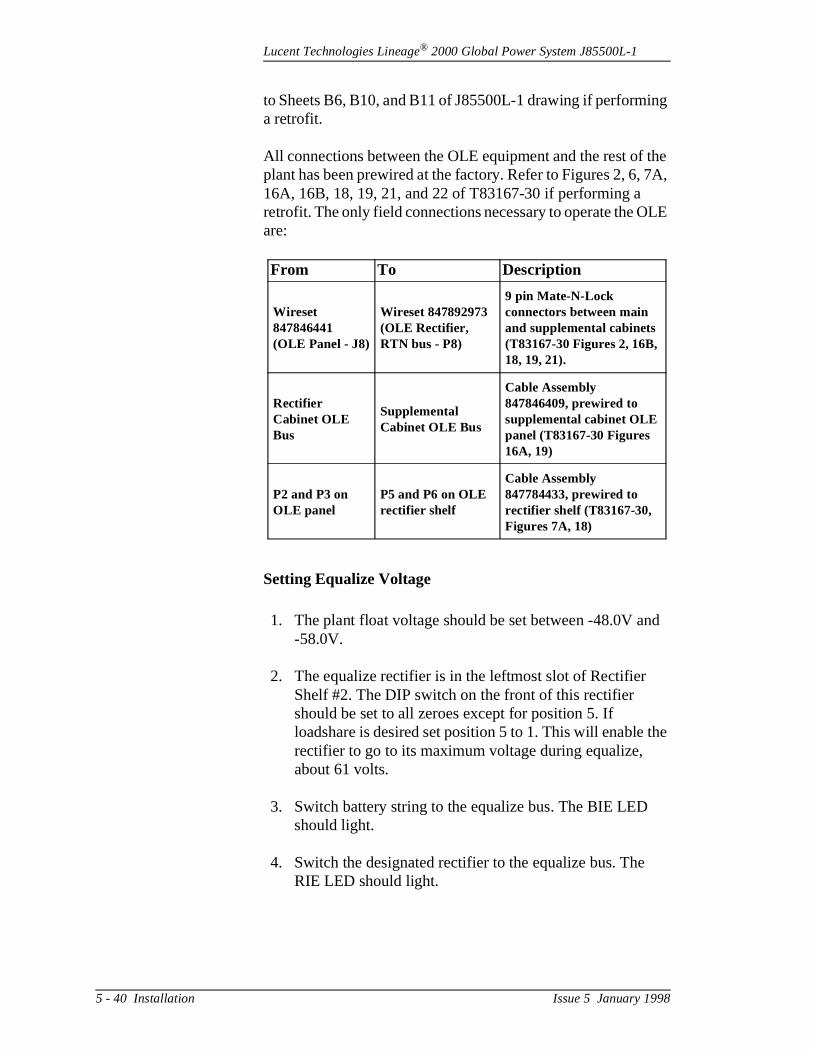
Lucent Technologies Lineage® 2000 Global Power System J85500L-1
ng
the 7A,
LE
d
the
to Sheets B6, B10, and B11 of J85500L-1 drawing if performia retrofit.
All connections between the OLE equipment and the rest of plant has been prewired at the factory. Refer to Figures 2, 6, 16A, 16B, 18, 19, 21, and 22 of T83167-30 if performing a retrofit. The only field connections necessary to operate the Oare:
Setting Equalize Voltage
1. The plant float voltage should be set between -48.0V an-58.0V.
2. The equalize rectifier is in the leftmost slot of Rectifier Shelf #2. The DIP switch on the front of this rectifier should be set to all zeroes except for position 5. If loadshare is desired set position 5 to 1. This will enable rectifier to go to its maximum voltage during equalize, about 61 volts.
3. Switch battery string to the equalize bus. The BIE LED should light.
4. Switch the designated rectifier to the equalize bus. TheRIE LED should light.
From To Description
Wireset 847846441 (OLE Panel - J8)
Wireset 847892973 (OLE Rectifier, RTN bus - P8)
9 pin Mate-N-Lock connectors between main and supplemental cabinets (T83167-30 Figures 2, 16B, 18, 19, 21).
Rectifier Cabinet OLE Bus
Supplemental Cabinet OLE Bus
Cable Assembly 847846409, prewired to supplemental cabinet OLE panel (T83167-30 Figures 16A, 19)
P2 and P3 on OLE panel
P5 and P6 on OLE rectifier shelf
Cable Assembly 847784433, prewired to rectifier shelf (T83167-30, Figures 7A, 18)
5 - 40 Installation Issue 5 January 1998
Lucent Technologies Lineage® 2000 Global Power System J85500L-1
ill ,
the
rn
all
e
us.h
ss
to
5. If these two steps are reversed, the BIE and RIE LEDs wflash alternately. Reset the rectifier and battery switchesthen restart the procedure.
6. Push the three-position switch toward the Equalize position. The “Eq1” LED should light.
7. Set the digital multimeter (DMM) to the appropriate DC voltage range and insert the probes into the test jacks ofOLE. Observe the voltage on the DMM and set the equalize voltage using a small slotted screw driver to tuthe “EQ1 Adjust” screw.
8. Depress the three-position Equalize switch to “Float.” Place the battery and rectifier back to normal operation;Equalize LEDs should extinguish.
OLE Installation Check Procedure
Follow the procedure below to verify installation of the Off-LinEqualize (OLE) Panel:
1. Start Equalize:
a. Switch battery string to be equalized to the equalize bb. Switch rectifier to equalize bus. (BIE and RIE will flas
if these two steps are reversed.)c. Set Equalize timer to desired position.d. Activate Equalize switch.
2. Stop Equalize:
a. Depress Equalize switch to “Float.”b. Monitor string voltage until string voltage is greater
than -58Vdc. (Voltages from -48Vdc to -57Vdc are greater than -58Vdc.
c. Switch rectifier to battery bus.d. If BIE and RIE are flashing, the equalization bus is le
than -58Vdc.e. If BIE and RIE are not flashing, switch battery string
battery bus.
3. Follow this procedure to equalize the remaining batterystrings.
Issue 5 January 1998 Installation 5 - 41

Lucent Technologies Lineage® 2000 Global Power System J85500L-1
re
e
ery
o n. ch
e
ys
Battery Connection
1. Remove all fuses from CP5 Fuse Board.
2. Confirm that the output circuit breakers of all rectifiers aopen.
3. Confirm that no fuses are inserted in the distribution fusholders.
4. Interconnect the battery strings as instructed by the battmanufacturer’s documentation.
5. Run all cables from the battery bus bar (- lead) and the return bus bar (+ lead) to the battery strings by first connecting them to the bus bars at the top of the batteryplant behind the ac box. Refer to Figure 2-17.
6. Terminate the cables from the battery plant bus bars ateach battery string according to the manufacturer’s documentation. Measure the resistance between the twends of any battery string to verify that the circuit is opeClose the last remaining part of the battery circuit on eastring (either intercell connector or disconnect breaker).
7. If the battery plant is equipped with a battery fuse disconnect panel (Lists E, F, H), install an NH3-size fusin both fuse holders. Fuse size should be determined byengineering based on battery size and rating.
8. Reinsert all fuses in CP5 Fuse Board. Match the fuse ratings and positions as indicated on the front panel.
DANGER
This procedure applies battery power to the battery plant. Before contacting any uninsulated conductor surfaces, alwause a voltmeter to insure that no voltage, or the expected voltage, is present.
5 - 42 Installation Issue 5 January 1998
Lucent Technologies Lineage® 2000 Global Power System J85500L-1
t re
the e
e
n ith
t
8 12 19
Adding a Load Circuit
1. Before installing load circuits, open the hinged doors covering the distribution fuse holders. Locate the EBB1alarm module(s) on the inside of the door and verify thaall alarm circuits are deactivated. (All dip switches, S1, aset to the open position.) The six position switch corresponds to the six red lights numbered from top to bottom.
2. Run paired leads (supply and return) to each load from distribution fuse holder and the discharge return bus. Thload supply leads are terminated at the fuse panels. NH2-size fuse holders are equipped with two M10 connection points for single hole connectors. Screws, lockwashers, and washers must be provided. NH00-sizfuse holders are equipped with M6 hardware. The load return leads are terminated at the battery plant to the discharge return bus bar located below the charge returbus bar at the top of the cabinet. This bus is equipped wtwelve M10 connection points and twenty-eight M8 connection points for single hole connectors. Hardwaremust be furnished.
3. Activate the alarm circuit for only the fuse position abouto be installed by closing the dip switch S1 on the EBB1
Note
The white indicators on F1 through F11 and F13 through F1represent a 1-1/3-ampere rating. The orange indicator on Frepresents a 2-ampere rating, and the green indicators on Fthrough F21 represent a 5-ampere rating.
DANGER
Battery voltage is present. Remove all jewelry and use onlyinsulated tools.
Caution
Alarms will be issued during the installation process. Notifythe alarm reporting center that alarms will be received.
Issue 5 January 1998 Installation 5 - 43

Lucent Technologies Lineage® 2000 Global Power System J85500L-1
e
nt
o
ors on . A n
:
8
alarm module that corresponds to that fuse position. Thred light should be illuminated and an alarm signal generated.
4. Install the required fuse for this position. The red light should extinguish and the alarm retire. If the fuse blowsimmediately on insertion, this may be due to inrush curreand does not necessarily indicate a fault condition. Addanother fuse. If the fuse blows again, check the wiring tthe load circuit.
5. When all load circuit additions are complete, close the distribution doors and notify the alarm reporting center.
Adding a Distribution Panel
The Global Power System (List 1) is equipped with hinged docovering each distribution position. When adding a distributipanel, always place the panel in the highest available positionbus bar connection is present for connecting each distributiopanel to the vertical charge bus (-48V). The following components should be furnished with each panel:
2 Mounting brackets8 M8 x 16mm screws2 M8 x 25mm screws10 M8 washers and lockwashers
EBB1 alarm module(s) as required4 Nylon standoffs per alarm module
The procedure for installing a distribution panel is as follows
1. Open hinged door of highest available distribution position.
2. Attach mounting brackets to cabinet using four M8 x 16 mm screws, lockwashers, and washers. Tighten to 1Nm (160 in-lb).
Caution
Before applying power to any individual load, follow the powering up instructions as provided in the associated loadequipment documentation.
5 - 44 Installation Issue 5 January 1998
Lucent Technologies Lineage® 2000 Global Power System J85500L-1
ers n nel o
8
to
r.
on
S1
le
ch
, a
to
3. Attach two M8 x 16 mm screws, lockwashers, and washto left mounting bracket. Do not tighten. Hang distributiopanel on left mounting bracket, making sure that the pabus contacts the plant bus bar on the outside. Attach twM8 x 16 mm screws, lockwashers, and washers to rightmounting bracket, securing the panel in place. Do not tighten.
4. Secure panel bus bar to plant bus bar with two M8 x 25 mm screws, lockwashers, and washers. Tighten to 1Nm (160 in-lb).
5. Secure panel to mounting brackets. Tighten four screws18 Nm (160 in-lb).
6. Remove alarm face plate located inside the hinged doo
7. Secure four nylon standoffs to the hinged door starting the left side. See Figure 5-9.
8. Snap EBB1 alarm module onto standoffs. Make sure allswitch positions are set to open position.
9. Repeat Steps 7 and 8 as required.
10. Attach wireset furnished with distribution panel to EBB1module(s) (six position connectors). Secure to wireset cable tie holders.
11. Alarm modules must be connected as shown in Figure 2-20. Attach the interconnection cable, which has been provided, with the panel from position P1 of alarm moduto position P2 of EBB1 alarm module located on the hinged door above. If this is the first distribution panel installed, this cable may be discarded. In this case, attathe connector from CP5 Fuse Board to position P1.
12. If more than one alarm module is provided with a panelsmall interconnection cable should also be provided. Connect this cable from connector P2 of the first EBB1 connector P1 of the second EBB1.
13. To insure proper operation of alarms, close one of the switch positions on the EBB1 module. A red light shouldappear on the module and the controller.
Issue 5 January 1998 Installation 5 - 45
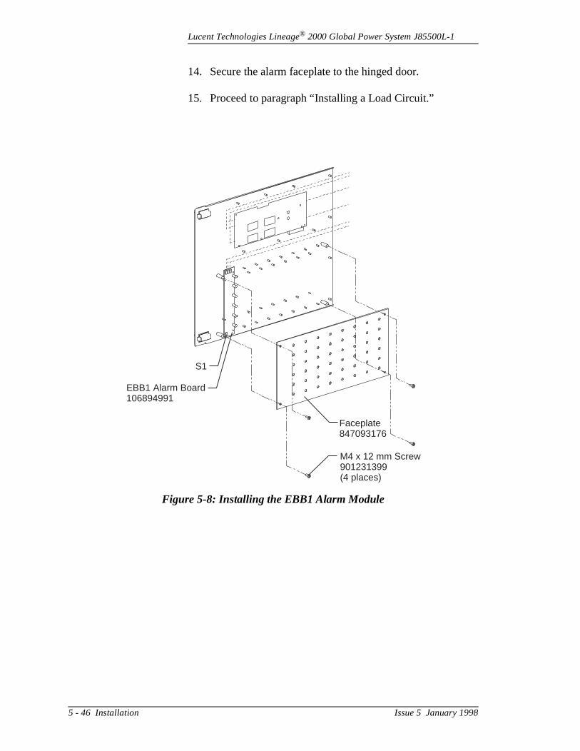
Lucent Technologies Lineage® 2000 Global Power System J85500L-1
14. Secure the alarm faceplate to the hinged door.
15. Proceed to paragraph “Installing a Load Circuit.”
Figure 5-8: Installing the EBB1 Alarm Module
S1
EBB1 Alarm Board106894991
Faceplate847093176
M4 x 12 mm Screw901231399(4 places)
5 - 46 Installation Issue 5 January 1998
Lucent Technologies Lineage® 2000 Global Power System J85500L-1
ht
be nt
al
d
AC Monitoring
AC MonitoringSetup
The procedure for setting up the AC Monitor Circuit is as follows:
1. Remove the snap-on covers from the right ac channel.
2. Open door to ac circuit breaker box.
3. Open controller door and pull out drawer.
4. Route the ac monitor interface wire set, comcode 847038882, from the ac circuit breaker box down the rigchannel and into the controller.
5. The wires are color-coded for easy reference and shouldterminated as shown on Table 5-D. Wires from the currelimiting resistor assemblies (R1-R6) in the ac box are equipped with pink plug-in connectors. The ac monitor interface wire set mates with these connectors. The interface wire set is terminated in the controller to terminblocks TB301 and TB302 on CP3 datalogger board.
6. Replace all snap-on covers on the right ac channel.
7. Close door to ac circuit breaker box.
Push in controller drawer and close the door.
Note
Both the Microprocessor (CP2) and the Datalogger Board (CP3) must be installed before the following procedure canbe followed.
Warning
Hazardous ac voltage. Extreme caution should be exercisewhen performing this procedure.
Issue 5 January 1998 Installation 5 - 47
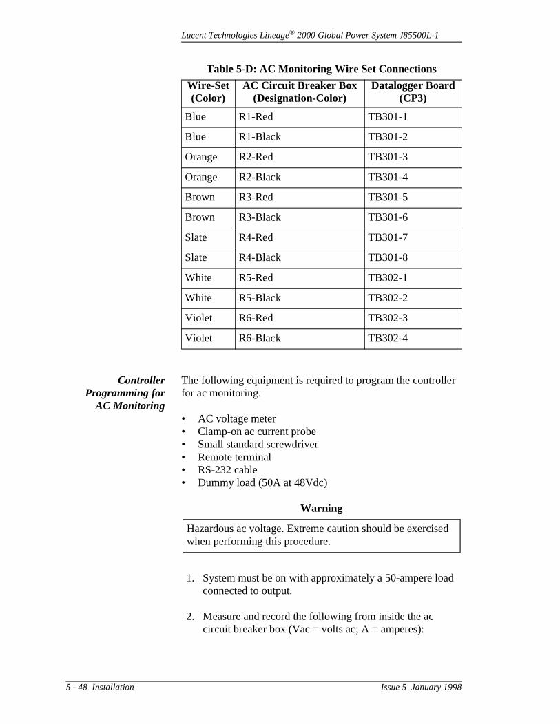
Lucent Technologies Lineage® 2000 Global Power System J85500L-1
r
d
d
ControllerProgramming for
AC Monitoring
The following equipment is required to program the controllefor ac monitoring.
• AC voltage meter• Clamp-on ac current probe• Small standard screwdriver• Remote terminal• RS-232 cable• Dummy load (50A at 48Vdc)
1. System must be on with approximately a 50-ampere loaconnected to output.
2. Measure and record the following from inside the ac circuit breaker box (Vac = volts ac; A = amperes):
Table 5-D: AC Monitoring Wire Set Connections
Wire-Set(Color)
AC Circuit Breaker Box(Designation-Color)
Datalogger Board(CP3)
Blue R1-Red TB301-1
Blue R1-Black TB301-2
Orange R2-Red TB301-3
Orange R2-Black TB301-4
Brown R3-Red TB301-5
Brown R3-Black TB301-6
Slate R4-Red TB301-7
Slate R4-Black TB301-8
White R5-Red TB302-1
White R5-Black TB302-2
Violet R6-Red TB302-3
Violet R6-Black TB302-4
Warning
Hazardous ac voltage. Extreme caution should be exercisewhen performing this procedure.
5 - 48 Installation Issue 5 January 1998
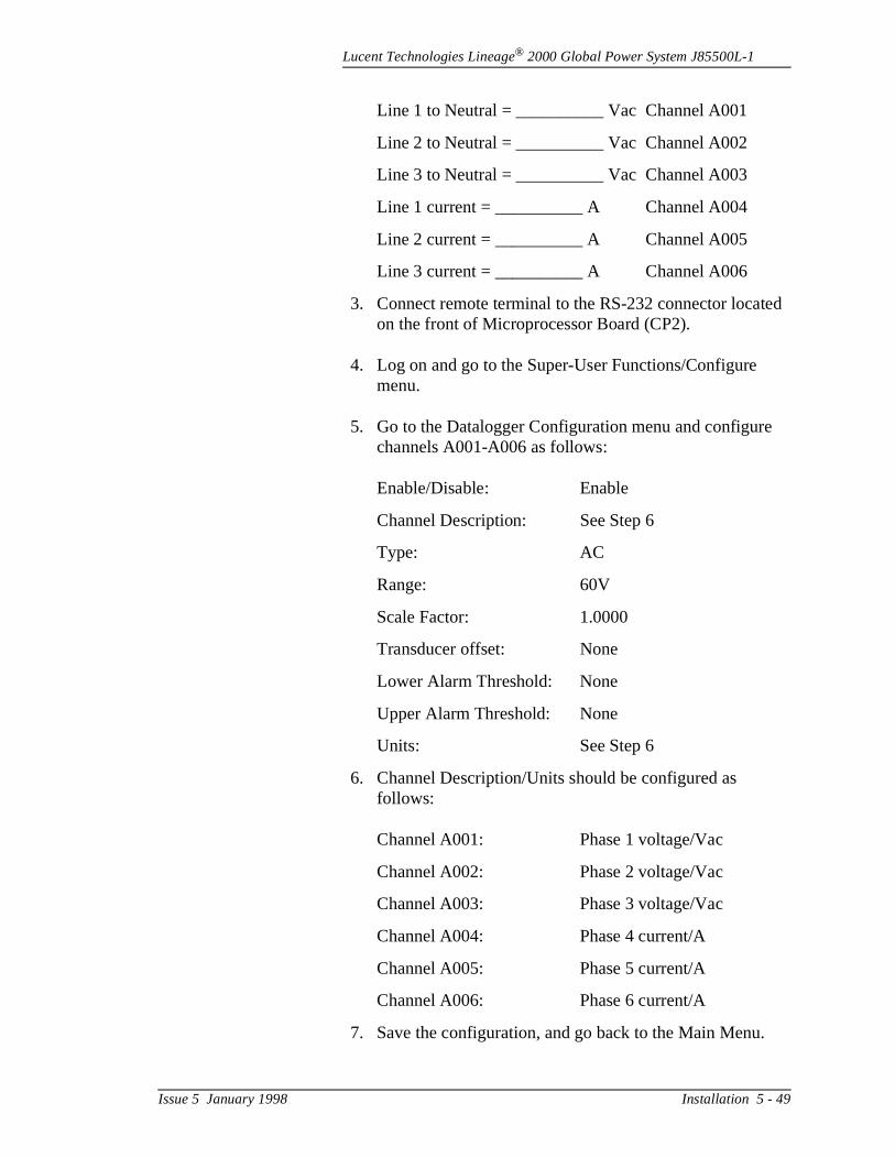
Lucent Technologies Lineage® 2000 Global Power System J85500L-1
ed
Line 1 to Neutral = __________ Vac Channel A001
Line 2 to Neutral = __________ Vac Channel A002
Line 3 to Neutral = __________ Vac Channel A003
Line 1 current = __________ A Channel A004
Line 2 current = __________ A Channel A005
Line 3 current = __________ A Channel A006
3. Connect remote terminal to the RS-232 connector locaton the front of Microprocessor Board (CP2).
4. Log on and go to the Super-User Functions/Configure menu.
5. Go to the Datalogger Configuration menu and configurechannels A001-A006 as follows:
Enable/Disable: Enable
Channel Description: See Step 6
Type: AC
Range: 60V
Scale Factor: 1.0000
Transducer offset: None
Lower Alarm Threshold: None
Upper Alarm Threshold: None
Units: See Step 6
6. Channel Description/Units should be configured as follows:
Channel A001: Phase 1 voltage/Vac
Channel A002: Phase 2 voltage/Vac
Channel A003: Phase 3 voltage/Vac
Channel A004: Phase 4 current/A
Channel A005: Phase 5 current/A
Channel A006: Phase 6 current/A
7. Save the configuration, and go back to the Main Menu.
Issue 5 January 1998 Installation 5 - 49
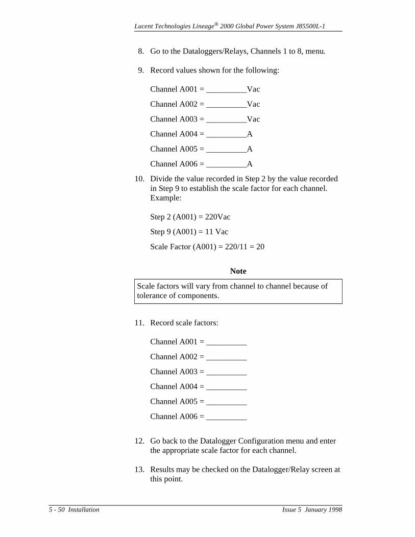
Lucent Technologies Lineage® 2000 Global Power System J85500L-1
ed
er
n at
8. Go to the Dataloggers/Relays, Channels 1 to 8, menu.
9. Record values shown for the following:
Channel A001 = __________Vac
Channel A002 = __________Vac
Channel A003 = __________Vac
Channel A004 = __________A
Channel A005 = __________A
Channel A006 = __________A
10. Divide the value recorded in Step 2 by the value recordin Step 9 to establish the scale factor for each channel. Example:
Step 2 (A001) = 220Vac
Step 9 (A001) = 11 Vac
Scale Factor (A001) = 220/11 = 20
11. Record scale factors:
Channel A001 = __________
Channel A002 = __________
Channel A003 = __________
Channel A004 = __________
Channel A005 = __________
Channel A006 = __________
12. Go back to the Datalogger Configuration menu and entthe appropriate scale factor for each channel.
13. Results may be checked on the Datalogger/Relay screethis point.
Note
Scale factors will vary from channel to channel because of tolerance of components.
5 - 50 Installation Issue 5 January 1998

Lucent Technologies Lineage® 2000 Global Power System J85500L-1
s
m the for ry
ght
ry
r
Shunt Monitoring
This procedure is for monitoring the two battery string shuntprovided with the List E battery fuse disconnect panel. The shunts have a full scale rating of 50 millivolts at the maximucurrent rating of 600 amperes. They are located at the top ofcabinet behind the ac box. The left fuse holder and shunt arebattery string 1. The right fuse holder and shunt are for battestring 2.
ShuntMonitoring Setup
1. Route two 18-gauge wires from each shunt down the riside of the cabinet to the controller.
2. Connect a black wire to the screw terminal on the battebus side of the shunts (top). Connect a red wire to the lower screw terminal of each shunt.
3. Open the controller door and pull out the drawer.
4. Terminate shunt wiring to terminal block TB302 on the CP3 datalogger board as follows:
Shunt Wire Color TB302 Pin
1 Black 5
1 Red 6
2 Black 7
2 Red 8
5. Push in the controller drawer and close the door.
ControllerProgramming forShunt Monitoring
The following equipment is required to program the controllefor shunt monitoring:
• Small standard screwdriver• Remote terminal• RS-232 cable
Note
Both the Microprocessor (CP2) and the Datalogger Board (CP3) must be installed before the following procedure canbe followed.
Issue 5 January 1998 Installation 5 - 51
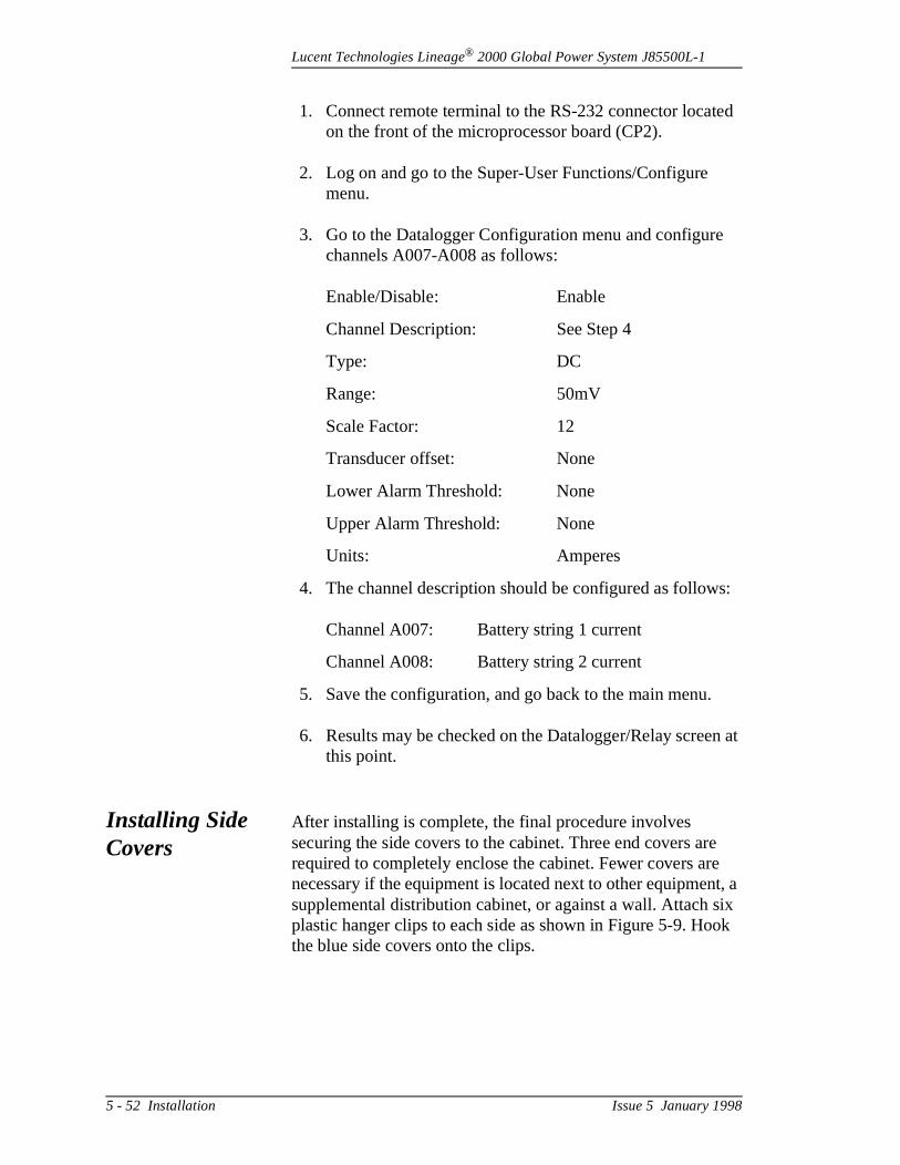
Lucent Technologies Lineage® 2000 Global Power System J85500L-1
ed
s:
n at
e e t, a ix ok
1. Connect remote terminal to the RS-232 connector locaton the front of the microprocessor board (CP2).
2. Log on and go to the Super-User Functions/Configure menu.
3. Go to the Datalogger Configuration menu and configurechannels A007-A008 as follows:
Enable/Disable: Enable
Channel Description: See Step 4
Type: DC
Range: 50mV
Scale Factor: 12
Transducer offset: None
Lower Alarm Threshold: None
Upper Alarm Threshold: None
Units: Amperes
4. The channel description should be configured as follow
Channel A007: Battery string 1 current
Channel A008: Battery string 2 current
5. Save the configuration, and go back to the main menu.
6. Results may be checked on the Datalogger/Relay screethis point.
Installing Side Covers
After installing is complete, the final procedure involves securing the side covers to the cabinet. Three end covers arrequired to completely enclose the cabinet. Fewer covers arnecessary if the equipment is located next to other equipmensupplemental distribution cabinet, or against a wall. Attach splastic hanger clips to each side as shown in Figure 5-9. Hothe blue side covers onto the clips.
5 - 52 Installation Issue 5 January 1998
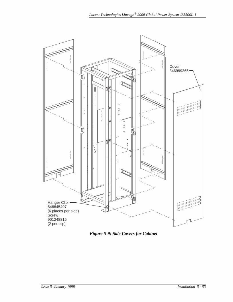
Lucent Technologies Lineage® 2000 Global Power System J85500L-1
Figure 5-9: Side Covers for Cabinet
Cover846999365
Hanger Clip846645497(6 places per side)Screw901248815(2 per clip)
Issue 5 January 1998 Installation 5 - 53
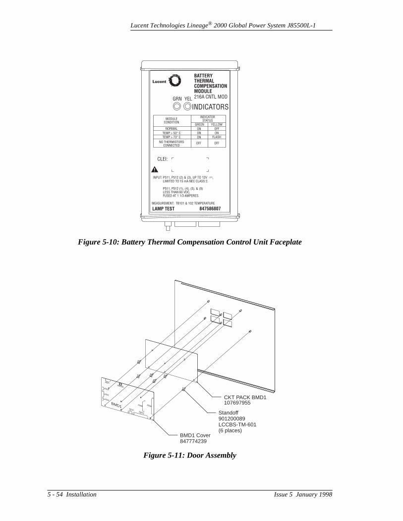
Lucent Technologies Lineage® 2000 Global Power System J85500L-1
Figure 5-10: Battery Thermal Compensation Control Unit Faceplate
BATTERY
THERMAL
COMPENSATION
MODULE
216A CNTL MODYEL
INDICATORSTATUS
GREEN
MODULECONDITION
NORMAL
TEMP > 53 C°TEMP > 73 C°
NO THERMISTORSCONNECTED
INPUT: P511, P512 (2) & (3), UP TO 12VLIMITED TO 15 mA NEC CLASS 2.
P511, P512 (1), (4), (5), & (9)LESS THAN 60 VDC,FUSED AT 1 1/3 AMPERES.
MEASUREMENT: TB101 & 102 TEMPERATURE
LAMP TEST 847586807
CLEI:
ON
ON ON
FLASH
OFFOFF
ON
YELLOW
OFF
GRN
INDICATORS
!
Lucent
Figure 5-11: Door Assembly
CKT PACK BMD1107697955
411
5
10 612
1
TB501
P510
P507SW500
BMD1
4
8
3
20
40
1
1
1
1
1
P502P508
P504
P501
P506
Standoff901200089LCCBS-TM-601(6 places)
BMD1 Cover847774239
5 - 54 Installation Issue 5 January 1998
Lucent Technologies Lineage® 2000 Global Power System J85500L-1
Figure 5-12: Placement of Thermistors in VR Battery Stand
BATTERY
THERMAL
COMPENSATION
MODULE
216A CNTL MODYEL
INDICATORSTATUS
GREEN
MODULECONDITION
NORMAL
TEMP > 53 C°TEMP > 73 C°
NO THERMISTORSCONNECTED
INPUT: P511, P512 (2) & (3), UP TO 12VLIMITED TO 15 mA NEC CLASS 2.
P511, P512 (1), (4), (5), & (9)LESS THAN 60 VDC,FUSED AT 1 1/3 AMPERES.
MEASUREMENT: TB101 & 102 TEMPERATURE
LAMP TEST 847586807
CLEI:
ON
ON ON
FLASH
OFFOFF
ON
YELLOW
OFF
GRN
INDICATORS
!
CU216A Thermal Compensation Module(Mounting Option 3)
See Fig. 5-14
P/O 847618048Thermistor Paddles
Lucent
Issue 5 January 1998 Installation 5 - 55
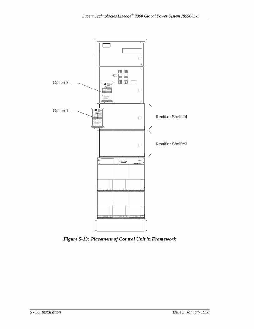
Lucent Technologies Lineage® 2000 Global Power System J85500L-1
Figure 5-13: Placement of Control Unit in Framework
LVD/R
LOAD
FAIL
OPEN
RECT
1
METER
CP2&3
CP1
CP1
RB
ABS
BAT
PWR
RECT
7
RECT
2
RECT
8
RECT
3
RECT
9
RECT
4
RECT
10
RECT
5
RECT
11
RECT
6
RECT
12
SPAREFUSES
1 1/3A
1 1/3A
1 1/3A
5A MAX
2A
BATTERY
THERMAL
COMPENSATION
MODULE
216A CNTL MODYEL
INDICATORSTATUS
GREEN
MODULECONDITION
NORMAL
TEMP > 53 C°TEMP > 73 C°
NO THERMISTORSCONNECTED
INPUT: P511, P512 (2) & (3), UP TO 12VLIMITED TO 15 mA NEC CLASS 2.
P511, P512 (1), (4), (5), & (9)LESS THAN 60 VDC,FUSED AT 1 1/3 AMPERES.
MEASUREMENT: TB101 & 102 TEMPERATURE
LAMP TEST 847586807
CLEI:
ON
ON ON
FLASH
OFFOFF
ON
YELLOW
OFF
GRN
INDICATORS
!
Lucent
Rectifier Shelf #4
Rectifier Shelf #3
Option 2
Option 1
5 - 56 Installation Issue 5 January 1998
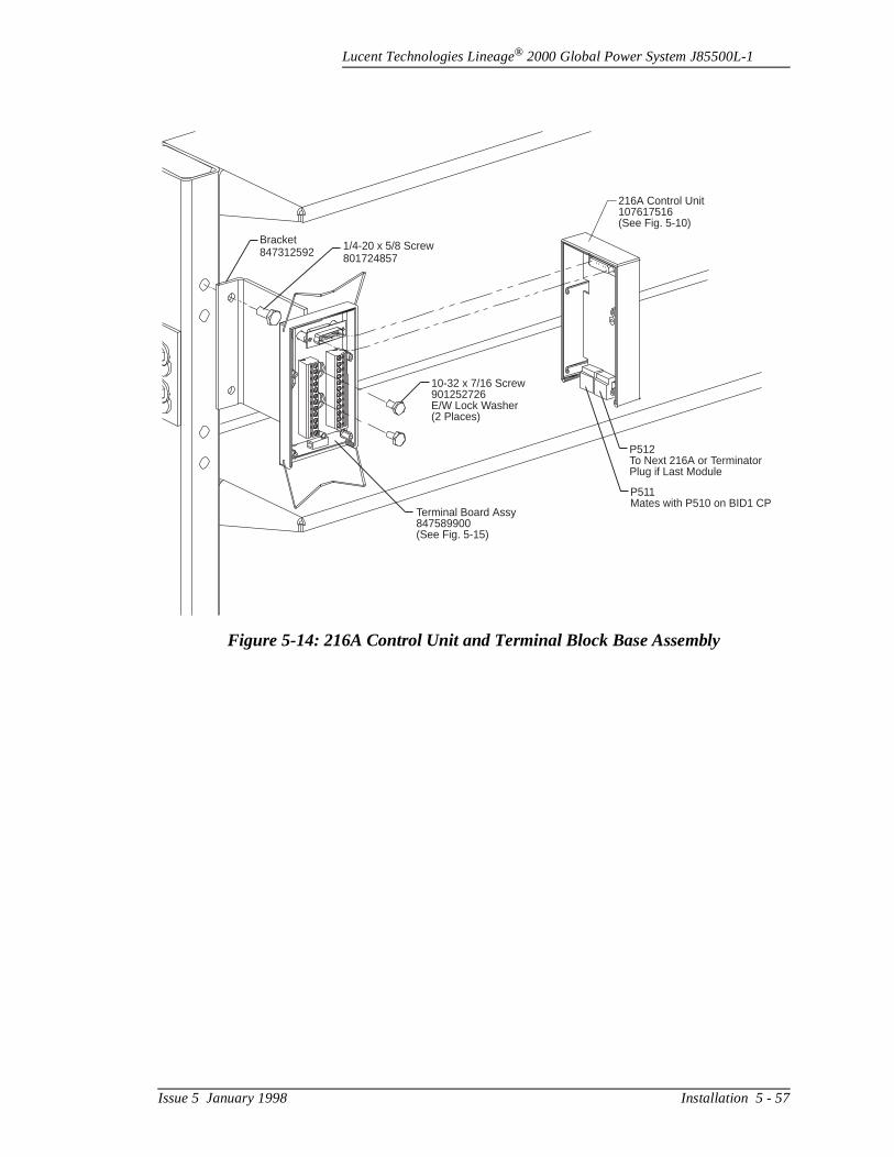
Lucent Technologies Lineage® 2000 Global Power System J85500L-1
Figure 5-14: 216A Control Unit and Terminal Block Base Assembly
1/4-20 x 5/8 Screw801724857
Bracket847312592
10-32 x 7/16 Screw901252726E/W Lock Washer(2 Places)
Terminal Board Assy847589900(See Fig. 5-15)
216A Control Unit107617516(See Fig. 5-10)
P512To Next 216A or TerminatorPlug if Last Module
P511Mates with P510 on BID1 CP
Issue 5 January 1998 Installation 5 - 57
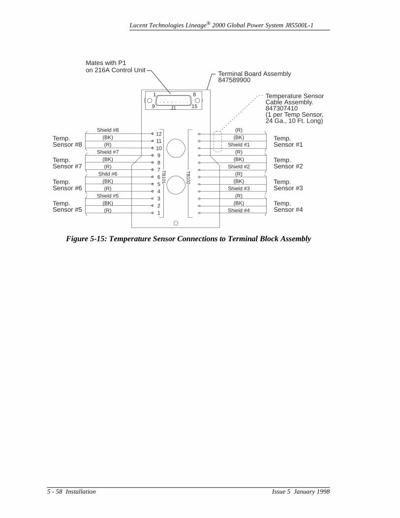
Lucent Technologies Lineage® 2000 Global Power System J85500L-1
Figure 5-15: Temperature Sensor Connections to Terminal Block Assembly
Mates with P1on 216A Control Unit
Terminal Board Assembly847589900
Temperature SensorCable Assembly.847307410(1 per Temp Sensor,24 Ga., 10 Ft. Long)
Temp.Sensor #1
Temp.Sensor #8
Temp.Sensor #2
Temp.Sensor #7
Temp.Sensor #3
Temp.Sensor #6
Temp.Sensor #4
Temp.Sensor #5
(R)(BK)
Shield #1(R)
(BK)Shield #2
(R)(BK)
Shield #3(R)
(BK)Shield #4
1 8
159 J1
Shield #8(BK)(R)
Shield #7(BK)(R)
Shild #6(BK)(R)
Shield #5(BK)(R)
121110987654321
TB
101
TB
102
5 - 58 Installation Issue 5 January 1998
Lucent Technologies Lineage® 2000 Global Power System J85500L-1
he ,
low
e e
2
e
ion
n d
he
Installing Thermal Compensation Unit in Existing Plant
The 216A ECS Thermal Compensation Unit described in Section 2 can be retrofitted into a J85500L-1 battery plant. TKit (Comcode 847774247) contains the circuit packs, wiringand hardware to monitor one string of batteries. The unit is shown in Figure 5-10. Read the instructions below before beginning, observe all the safety warnings and notes, and folthe instructions step by step.
Tools required:
• 5/16” Nutdriver• 7/16” Nutdriver• Jeweler’s Screwdriver• Wire Strippers (22 AWG)• Heat Gun
Observe all safety warnings and notes before beginning installation.
InstallationProcedure
1. For use with Lucent VR Batteries: Mount the VR Modulbracket to any one of the available x - 20 Pem-nuts in thbattery stand upright. Then attach the Terminal Block Assembly Base to the VR Module bracket with the 10-3screws provided. (See Figure 5-13.)
For use with alternate vendor batteries, three options arrecommended:
Option 1: Mount the VR Module bracket to the plant framework (List 1 or List 20) in an unused end rectifier position using the two 10-32 screws that have been provided. Consider further plant growth (rectifier shelves/rectifiers) before choosing this option. (See Opt1 on Figure 5-13.)
Option 2: Mount the 216A Control Unit on the distributiodoor panel (lower left corner) using the adhesive backeVelcro strips provided. Make sure the surface of the distribution door is clean before peeling the backing off t
Caution
Procedures in this section may cause power alarms to be issued temporarily. Notify the alarm reporting center beforestarting any replacement procedure to an operating plant.
Issue 5 January 1998 Installation 5 - 59

Lucent Technologies Lineage® 2000 Global Power System J85500L-1
s d
g r
x
s s
ll g
A)
re er
r
Velcro hooks and affixing to the distribution door. Makesure the back surface of the Terminal Block Assembly iclean before peeling the backing off the Velcro loops anaffixing to the Terminal Block Assembly. Mount the Terminal Block Assembly on the distribution door. Consider the protrusion of the 216 Control Unit before choosing this option. (See Option 2 on Figure 5-13.)
Option 3: Mount the 216A Control Unit on the battery stand (not the batteries) in any convenient location usineither the VR Module bracket and 1 or 2 10-32 screws ousing the Velcro strips. If the Velcro strips are used, affithe Velcro hooks to a clean surface on the battery standand the Velcro loops to the back of the Terminal Block Assembly (must be cleaned). Consider the distance between the battery plant and the battery stand before choosing this option. (See Option 3 on Figure 5-12.)
2. Temporarily insert the thermistors in the battery locationto be monitored. See Figure 5-12 for suggested locationbetween the Lucent VR Batteries. Dress the thermistor wire sets from the Terminal Block Assembly to the thermistors and cut to proper length. The thermistors wineed to be removed from the battery string during testinso do not secure them into place at this time.
3. Connect all thermistor wire sets (maximum = 8 per 216to terminal blocks TB101 and TB102 as shown in 5-15. The ambient temperature of the thermistor must be between 0° C (32° F) and 53° C (127.4° F) when the wiset is connected to the Terminal Block Assembly in ordfor the proper temperature to be sensed by the 216A Control Unit.
4. Mate the 216A Control Unit to the Terminal Block BaseAssembly. See Figure 5-14. Latch the two units togethewith the clips on the base.
5. Repeat steps 1 through 3 for additional battery strings.
6. Open distribution door.
7. Unplug the following connectors from the BCB2 LVD/Fuse Board. Leave the cables dressed.
5 - 60 Installation Issue 5 January 1998
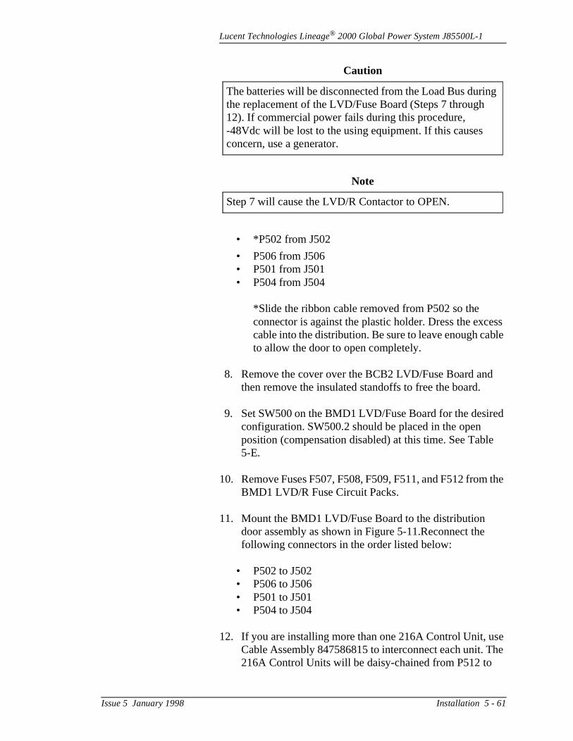
Lucent Technologies Lineage® 2000 Global Power System J85500L-1
ess ble
ed
the
se he
g
• *P502 from J502
• P506 from J506• P501 from J501• P504 from J504
*Slide the ribbon cable removed from P502 so the connector is against the plastic holder. Dress the exccable into the distribution. Be sure to leave enough cato allow the door to open completely.
8. Remove the cover over the BCB2 LVD/Fuse Board andthen remove the insulated standoffs to free the board.
9. Set SW500 on the BMD1 LVD/Fuse Board for the desirconfiguration. SW500.2 should be placed in the open position (compensation disabled) at this time. See Table5-E.
10. Remove Fuses F507, F508, F509, F511, and F512 fromBMD1 LVD/R Fuse Circuit Packs.
11. Mount the BMD1 LVD/Fuse Board to the distribution door assembly as shown in Figure 5-11.Reconnect the following connectors in the order listed below:
• P502 to J502• P506 to J506• P501 to J501• P504 to J504
12. If you are installing more than one 216A Control Unit, uCable Assembly 847586815 to interconnect each unit. T216A Control Units will be daisy-chained from P512 to
Caution
The batteries will be disconnected from the Load Bus durinthe replacement of the LVD/Fuse Board (Steps 7 through 12). If commercial power fails during this procedure, -48Vdc will be lost to the using equipment. If this causes concern, use a generator.
Note
Step 7 will cause the LVD/R Contactor to OPEN.
Issue 5 January 1998 Installation 5 - 61
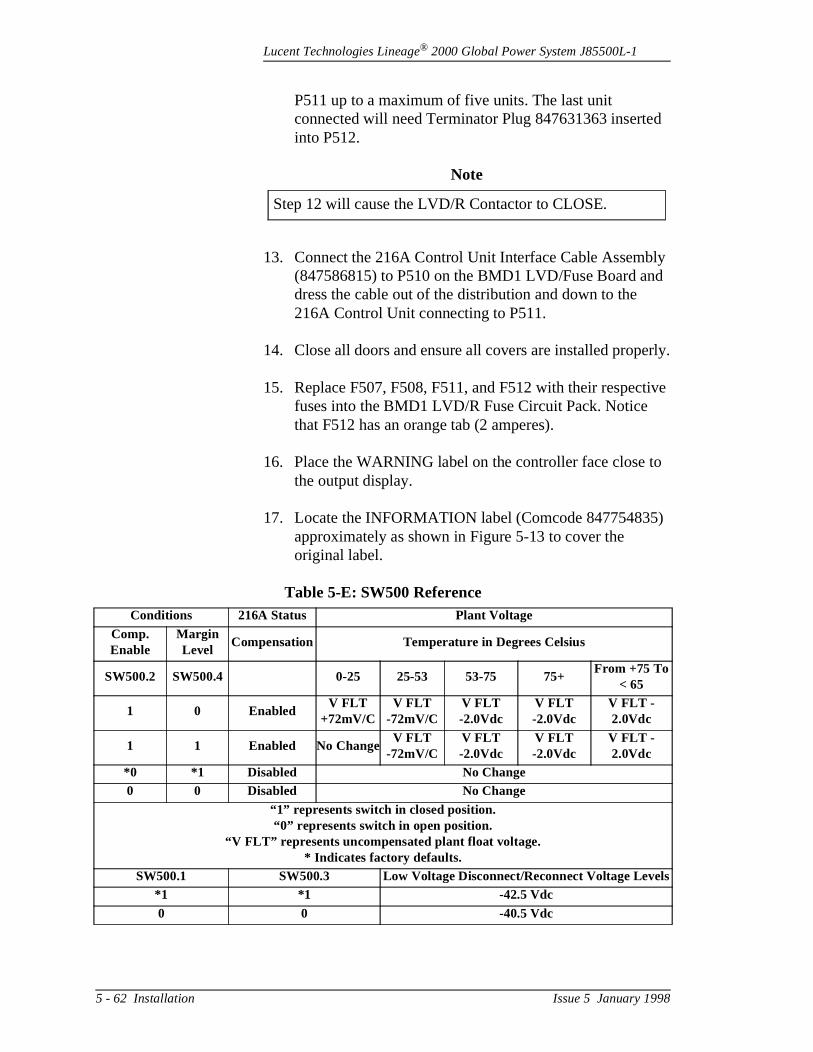
Lucent Technologies Lineage® 2000 Global Power System J85500L-1
d
ly d
erly.
tive
to
)
s
P511 up to a maximum of five units. The last unit connected will need Terminator Plug 847631363 inserteinto P512.
13. Connect the 216A Control Unit Interface Cable Assemb(847586815) to P510 on the BMD1 LVD/Fuse Board andress the cable out of the distribution and down to the 216A Control Unit connecting to P511.
14. Close all doors and ensure all covers are installed prop
15. Replace F507, F508, F511, and F512 with their respecfuses into the BMD1 LVD/R Fuse Circuit Pack. Notice that F512 has an orange tab (2 amperes).
16. Place the WARNING label on the controller face close the output display.
17. Locate the INFORMATION label (Comcode 847754835approximately as shown in Figure 5-13 to cover the original label.
Note
Step 12 will cause the LVD/R Contactor to CLOSE.
Table 5-E: SW500 ReferenceConditions 216A Status Plant Voltage
Comp. Enable
Margin Level
Compensation Temperature in Degrees Celsius
SW500.2 SW500.4 0-25 25-53 53-75 75+From +75 To
< 65
1 0 EnabledV FLT
+72mV/CV FLT
-72mV/CV FLT -2.0Vdc
V FLT -2.0Vdc
V FLT - 2.0Vdc
1 1 Enabled No ChangeV FLT
-72mV/CV FLT -2.0Vdc
V FLT -2.0Vdc
V FLT - 2.0Vdc
*0 *1 Disabled No Change0 0 Disabled No Change
“1” represents switch in closed position.“0” represents switch in open position.
“V FLT” represents uncompensated plant float voltage.* Indicates factory defaults.
SW500.1 SW500.3 Low Voltage Disconnect/Reconnect Voltage Level*1 *1 -42.5 Vdc0 0 -40.5 Vdc
5 - 62 Installation Issue 5 January 1998
Lucent Technologies Lineage® 2000 Global Power System J85500L-1
D1 ll
nit
CS
e
e
e
o g IP
Test Procedure
1. Open the distribution door and set SW500.2 on the BMLVD/R Fuse Circuit Pack to the closed position. This wienable the compensation feature. Close the distributiondoor.
2. Check to see that the green LED on the 216A Control Uis ON.
3. Verify that there are no alarms being generated on the EController.
4. Thermistors should be heated with INDIRECT air flow from a heat gun. Heat applied directly to the thermistor could cause damage.
5. The following steps should be observed:
• A minor fuse alarm (MNF) should be issued at approximately the same time that the yellow LED on th216A Control Unit is turned on which should correspond to a two-volt drop in the float voltage.
• A major fuse alarm (MJF) should be issued at the samtime as the yellow LED on the 216A Control Unit begins blinking. The six-volt drop will not be seen because the batteries will not discharge that quickly.
• The thermistors should be allowed to cool and then binserted and secured into the battery string.
• Verify there are no alarms present at this time.
Note
It is recommended to reset the BD alarm on the controller t3.0 Vdc below the float voltage. The HVSD level should bereset to 3.0 Vdc above the float voltage when the margininfeature is enabled. See J85500L-1 assembly drawing for Dswitch settings.
Issue 5 January 1998 Installation 5 - 63
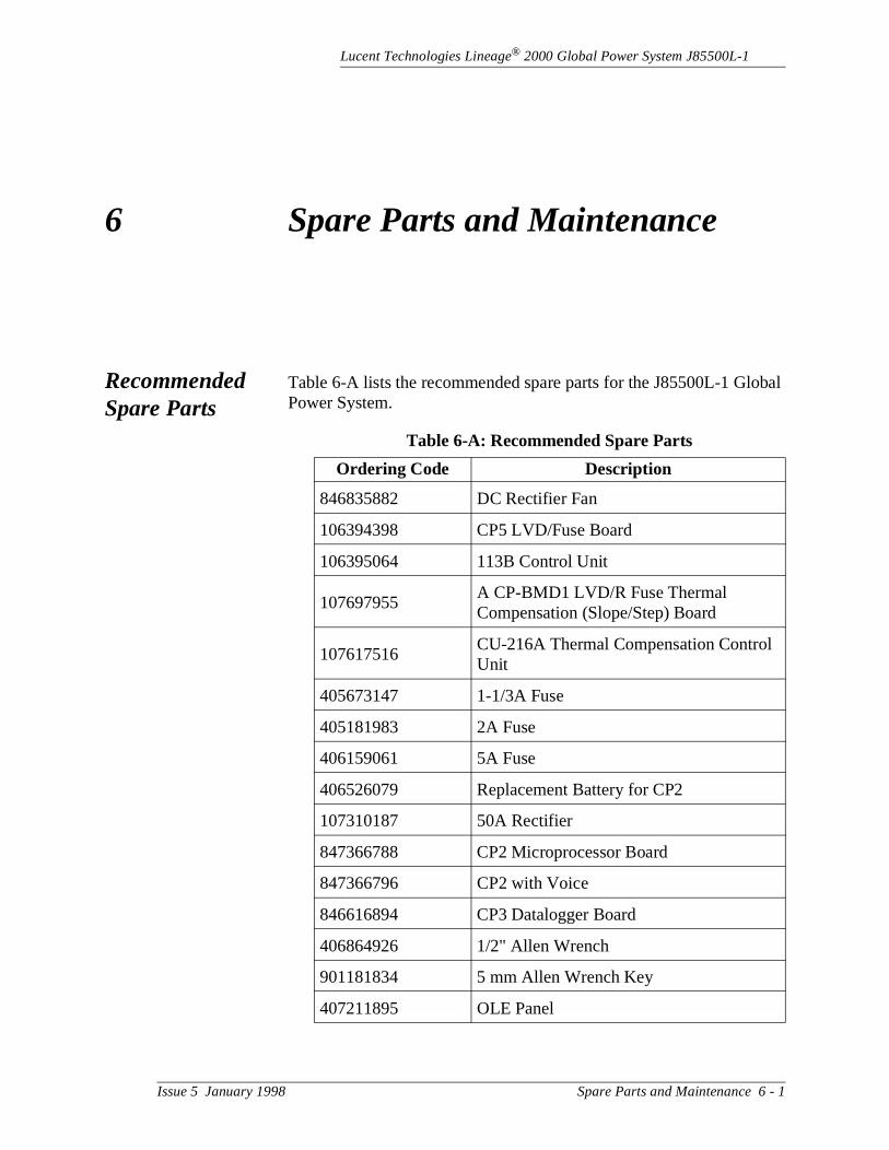
Lucent Technologies Lineage® 2000 Global Power System J85500L-1
obal
6 Spare Parts and Maintenance
Recommended Spare Parts
Table 6-A lists the recommended spare parts for the J85500L-1 GlPower System.
Table 6-A: Recommended Spare Parts
Ordering Code Description
846835882 DC Rectifier Fan
106394398 CP5 LVD/Fuse Board
106395064 113B Control Unit
107697955A CP-BMD1 LVD/R Fuse Thermal Compensation (Slope/Step) Board
107617516CU-216A Thermal Compensation Control Unit
405673147 1-1/3A Fuse
405181983 2A Fuse
406159061 5A Fuse
406526079 Replacement Battery for CP2
107310187 50A Rectifier
847366788 CP2 Microprocessor Board
847366796 CP2 with Voice
846616894 CP3 Datalogger Board
406864926 1/2" Allen Wrench
901181834 5 mm Allen Wrench Key
407211895 OLE Panel
Issue 5 January 1998 Spare Parts and Maintenance 6 - 1
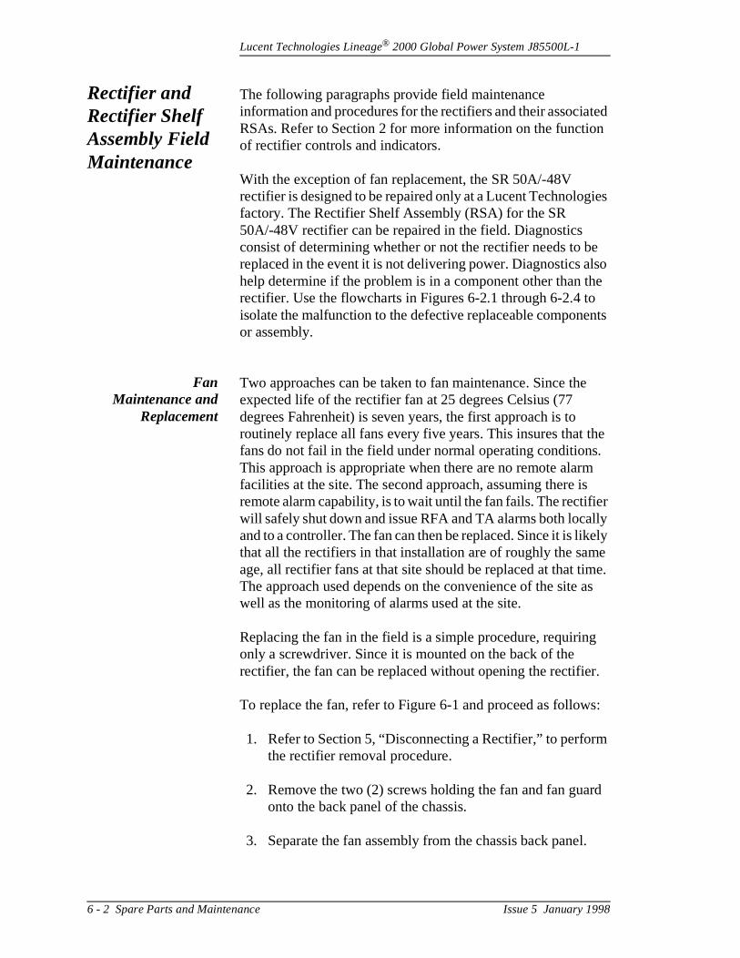
Lucent Technologies Lineage® 2000 Global Power System J85500L-1
ted n
ies
e lso he nts
e
he .
m s er lly ely e
me. as
g
r.
s:
m
rd
l.
Rectifier and Rectifier Shelf Assembly Field Maintenance
The following paragraphs provide field maintenance information and procedures for the rectifiers and their associaRSAs. Refer to Section 2 for more information on the functioof rectifier controls and indicators.
With the exception of fan replacement, the SR 50A/-48V rectifier is designed to be repaired only at a Lucent Technologfactory. The Rectifier Shelf Assembly (RSA) for the SR 50A/-48V rectifier can be repaired in the field. Diagnostics consist of determining whether or not the rectifier needs to breplaced in the event it is not delivering power. Diagnostics ahelp determine if the problem is in a component other than trectifier. Use the flowcharts in Figures 6-2.1 through 6-2.4 toisolate the malfunction to the defective replaceable componeor assembly.
FanMaintenance and
Replacement
Two approaches can be taken to fan maintenance. Since thexpected life of the rectifier fan at 25 degrees Celsius (77 degrees Fahrenheit) is seven years, the first approach is to routinely replace all fans every five years. This insures that tfans do not fail in the field under normal operating conditionsThis approach is appropriate when there are no remote alarfacilities at the site. The second approach, assuming there iremote alarm capability, is to wait until the fan fails. The rectifiwill safely shut down and issue RFA and TA alarms both locaand to a controller. The fan can then be replaced. Since it is likthat all the rectifiers in that installation are of roughly the samage, all rectifier fans at that site should be replaced at that tiThe approach used depends on the convenience of the sitewell as the monitoring of alarms used at the site.
Replacing the fan in the field is a simple procedure, requirinonly a screwdriver. Since it is mounted on the back of the rectifier, the fan can be replaced without opening the rectifie
To replace the fan, refer to Figure 6-1 and proceed as follow
1. Refer to Section 5, “Disconnecting a Rectifier,” to perforthe rectifier removal procedure.
2. Remove the two (2) screws holding the fan and fan guaonto the back panel of the chassis.
3. Separate the fan assembly from the chassis back pane
6 - 2 Spare Parts and Maintenance Issue 5 January 1998
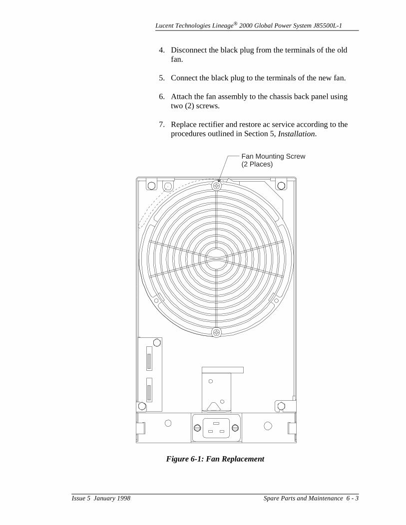
Lucent Technologies Lineage® 2000 Global Power System J85500L-1
g
4. Disconnect the black plug from the terminals of the old fan.
5. Connect the black plug to the terminals of the new fan.
6. Attach the fan assembly to the chassis back panel usintwo (2) screws.
7. Replace rectifier and restore ac service according to theprocedures outlined in Section 5, Installation.
Figure 6-1: Fan Replacement
Fan Mounting Screw(2 Places)
Issue 5 January 1998 Spare Parts and Maintenance 6 - 3
Lucent Technologies Lineage® 2000 Global Power System J85500L-1
g
ch
Required TestEquipment
Depending on the tests to be performed, one or more of thefollowing may be required.
• DMM (Digital Multimeter) Fluke 8060A or equivalent meter having .05% accuracy on dc scale
• Jeweler's Screwdriver for adjusting potentiometer.• 5mm Allen wrench for replacing rectifiers.
Replacing theRectifier
In the event the rectifier has to be replaced, follow the stepsoutlined in Section 5, Installation.
Troubleshooting
Rectifier Figures 6-2.1 through 6-2.2 are flowcharts for troubleshootinthe -48-volt, 50-ampere switchmode rectifier.
Controller This section contains four tables and five flowcharts for the purpose of troubleshooting the ECS-12 Controller, verifying controller alarms, and meter calibration. The flowcharts, whifollow the tables, are listed below.
A. Office Alarms Received Figure 6-3
B. 113B Control Unit Has Lost PowerFigures 6-4.1 through 6-4.3
C. Verify Controller AlarmsFigures 6-5.1 through 6-5.5
D. Display Is Not lit Figure 6-6
E. Meter Out of Calibration Figure 6-7
6 - 4 Spare Parts and Maintenance Issue 5 January 1998
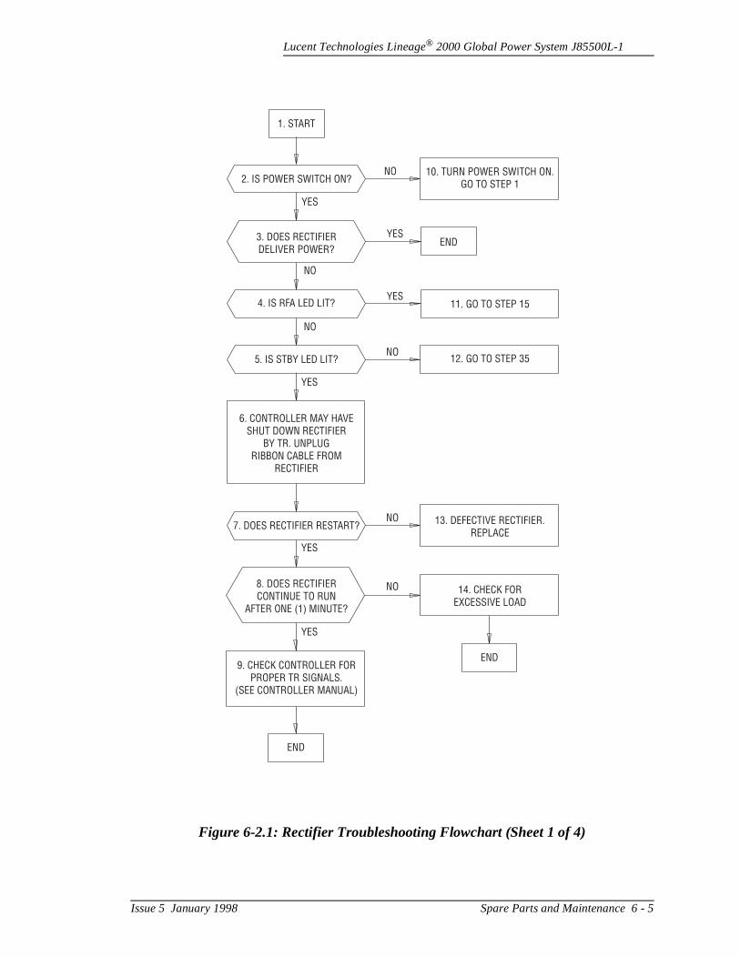
Lucent Technologies Lineage® 2000 Global Power System J85500L-1
Figure 6-2.1: Rectifier Troubleshooting Flowchart (Sheet 1 of 4)
1. START
3. DOES RECTIFIERDELIVER POWER?
4. IS RFA LED LIT?
5. IS STBY LED LIT?
2. IS POWER SWITCH ON?
7. DOES RECTIFIER RESTART?
8. DOES RECTIFIERCONTINUE TO RUN
AFTER ONE (1) MINUTE?
9. CHECK CONTROLLER FORPROPER TR SIGNALS.
(SEE CONTROLLER MANUAL)
END
END
6. CONTROLLER MAY HAVESHUT DOWN RECTIFIER
BY TR. UNPLUGRIBBON CABLE FROM
RECTIFIER
YES
YES
NO
NO
NO
NO
NO
NO
YES
YES
YES
YES
END
11. GO TO STEP 15
12. GO TO STEP 35
10. TURN POWER SWITCH ON.GO TO STEP 1
13. DEFECTIVE RECTIFIER.REPLACE
14. CHECK FOREXCESSIVE LOAD
Issue 5 January 1998 Spare Parts and Maintenance 6 - 5
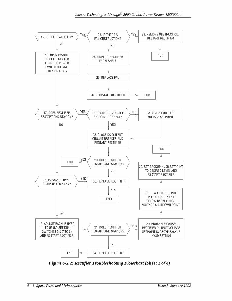
Lucent Technologies Lineage® 2000 Global Power System J85500L-1
Figure 6-2.2: Rectifier Troubleshooting Flowchart (Sheet 2 of 4)
15. IS TA LED ALSO LIT?
16. OPEN DC-OUTCIRCUIT BREAKERTURN THE POWERSWITCH OFF ANDTHEN ON AGAIN
17. DOES RECTIFIERRESTART AND STAY ON?
23. IS THERE AFAN OBSTRUCTION?
24. UNPLUG RECTIFIERFROM SHELF
25. REPLACE FAN
26. REINSTALL RECTIFIER
27. IS OUTPUT VOLTAGESETPOINT CORRECT?
28. CLOSE DC OUTPUTCIRCUIT BREAKER AND
RESTART RECTIFIER
29. DOES RECTIFIERRESTART AND STAY ON?
31. DOES RECTIFIERRESTART AND STAY ON?
18. IS BACKUP HVSDADJUSTED TO 59.5V?
19. ADJUST BACKUP HVSDTO 59.5V (SET DIP
SWITCHES 6 & 7 TO 0)AND RESTART RECTIFIER
30. REPLACE RECTIFIER
34. REPLACE RECTIFIER
22. SET BACKUP HVSD SETPOINTTO DESIRED LEVEL AND
RESTART RECTIFIER
21. READJUST OUTPUTVOLTAGE SETPOINT
BELOW BACKUP HIGHVOLTAGE SHUTDOWN POINT
20. PROBABLE CAUSE:RECTIFIER OUTPUT VOLTAGESETPOINT IS ABOVE BACKUP
HVSD SETTING
33. ADJUST OUTPUTVOLTAGE SETPOINT
32. REMOVE OBSTRUCTION.RESTART RECTIFIER
END
END
YES YES
NONO
NO
NO
NOYES
YES
YES
YES
YES
YES
NO
NO
END
END
END
END
6 - 6 Spare Parts and Maintenance Issue 5 January 1998
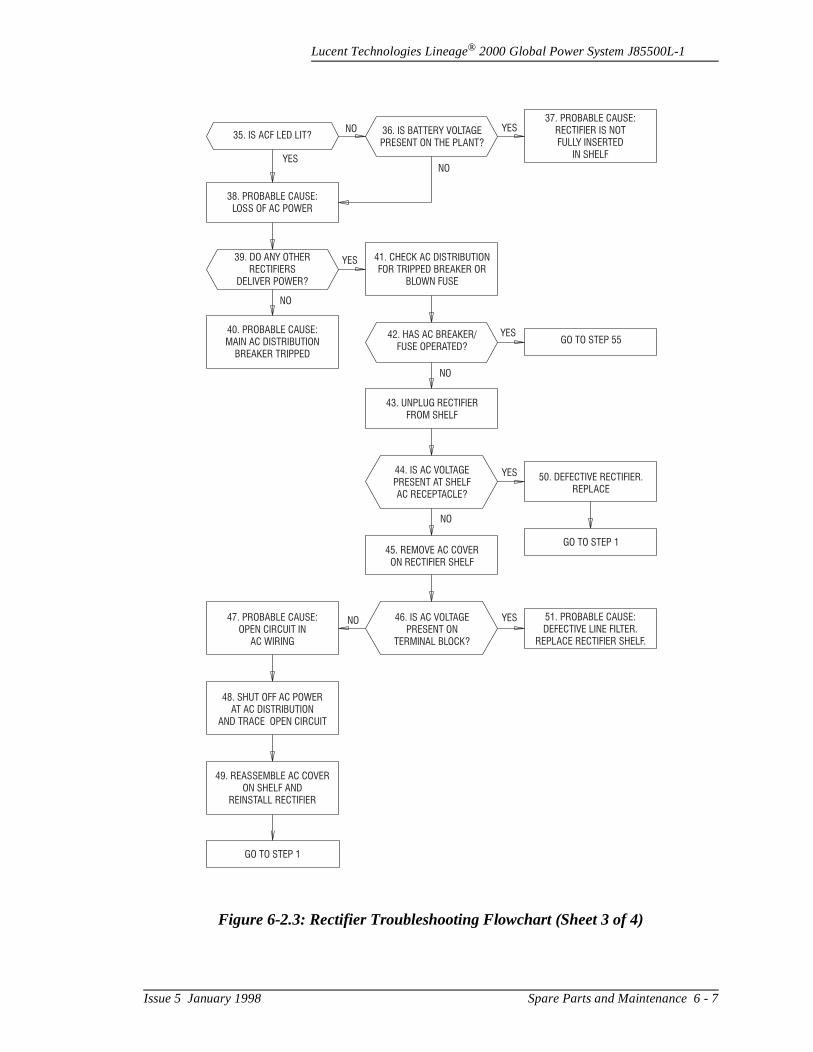
Lucent Technologies Lineage® 2000 Global Power System J85500L-1
Figure 6-2.3: Rectifier Troubleshooting Flowchart (Sheet 3 of 4)
35. IS ACF LED LIT?
38. PROBABLE CAUSE:
LOSS OF AC POWER
39. DO ANY OTHER
RECTIFIERS
DELIVER POWER?
40. PROBABLE CAUSE:
MAIN AC DISTRIBUTION
BREAKER TRIPPED
41. CHECK AC DISTRIBUTION
FOR TRIPPED BREAKER OR
BLOWN FUSE
42. HAS AC BREAKER/
FUSE OPERATED?
43. UNPLUG RECTIFIER
FROM SHELF
44. IS AC VOLTAGE
PRESENT AT SHELF
AC RECEPTACLE?
45. REMOVE AC COVER
ON RECTIFIER SHELF
46. IS AC VOLTAGE
PRESENT ON
TERMINAL BLOCK?
47. PROBABLE CAUSE:
OPEN CIRCUIT IN
AC WIRING
48. SHUT OFF AC POWER
AT AC DISTRIBUTION
AND TRACE OPEN CIRCUIT
49. REASSEMBLE AC COVER
ON SHELF AND
REINSTALL RECTIFIER
51. PROBABLE CAUSE:
DEFECTIVE LINE FILTER.
REPLACE RECTIFIER SHELF.
GO TO STEP 1
GO TO STEP 55
GO TO STEP 1
50. DEFECTIVE RECTIFIER.
REPLACE
36. IS BATTERY VOLTAGE
PRESENT ON THE PLANT?
37. PROBABLE CAUSE:
RECTIFIER IS NOT
FULLY INSERTED
IN SHELFYES
YES
NO
NO
YES
YES
NO
NO YES
YESNO
NO
Issue 5 January 1998 Spare Parts and Maintenance 6 - 7
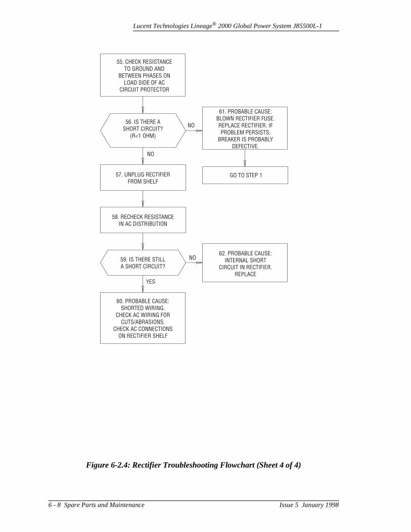
Lucent Technologies Lineage® 2000 Global Power System J85500L-1
Figure 6-2.4: Rectifier Troubleshooting Flowchart (Sheet 4 of 4)
55. CHECK RESISTANCETO GROUND AND
BETWEEN PHASES ONLOAD SIDE OF AC
CIRCUIT PROTECTOR
56. IS THERE ASHORT CIRCUIT?
(R<1 OHM)
57. UNPLUG RECTIFIERFROM SHELF
58. RECHECK RESISTANCEIN AC DISTRIBUTION
59. IS THERE STILLA SHORT CIRCUIT?
60. PROBABLE CAUSE:SHORTED WIRING.
CHECK AC WIRING FORCUTS/ABRASIONS.
CHECK AC CONNECTIONSON RECTIFIER SHELF
61. PROBABLE CAUSE:BLOWN RECTIFIER FUSE.REPLACE RECTIFIER. IFPROBLEM PERSISTS,
BREAKER IS PROBABLYDEFECTIVE.
62. PROBABLE CAUSE:INTERNAL SHORT
CIRCUIT IN RECTIFIER.REPLACE
GO TO STEP 1
NO
NO
NO
YES
6 - 8 Spare Parts and Maintenance Issue 5 January 1998
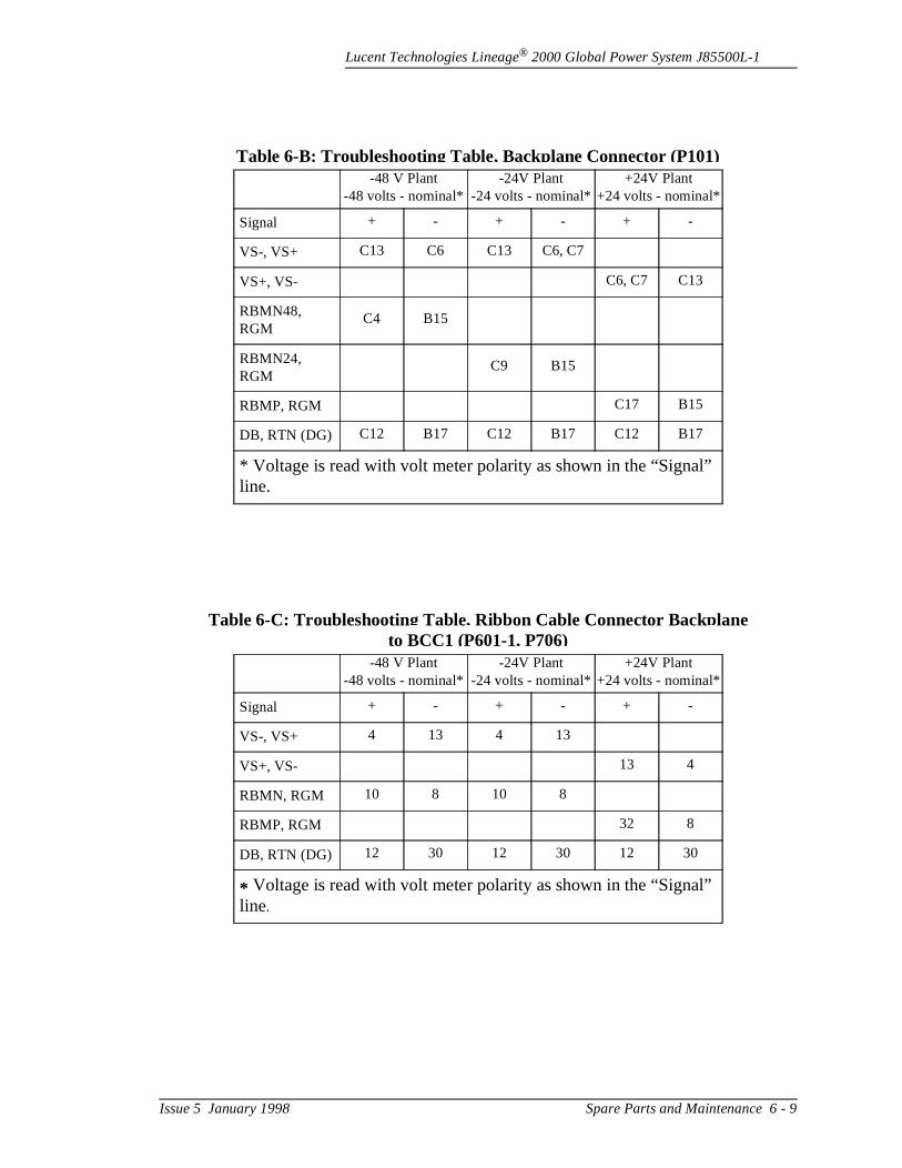
Lucent Technologies Lineage® 2000 Global Power System J85500L-1
Table 6-B: Troubleshooting Table, Backplane Connector (P101)-48 V Plant
-48 volts - nominal*-24V Plant
-24 volts - nominal*+24V Plant
+24 volts - nominal*
Signal + - + - + -
VS-, VS+ C13 C6 C13 C6, C7
VS+, VS- C6, C7 C13
RBMN48, RGM
C4 B15
RBMN24, RGM
C9 B15
RBMP, RGM C17 B15
DB, RTN (DG) C12 B17 C12 B17 C12 B17
* Voltage is read with volt meter polarity as shown in the “Signal” line.
Table 6-C: Troubleshooting Table, Ribbon Cable Connector Backplane to BCC1 (P601-1, P706)
-48 V Plant-48 volts - nominal*
-24V Plant -24 volts - nominal*
+24V Plant+24 volts - nominal*
Signal + - + - + -
VS-, VS+ 4 13 4 13
VS+, VS- 13 4
RBMN, RGM 10 8 10 8
RBMP, RGM 32 8
DB, RTN (DG) 12 30 12 30 12 30
* Voltage is read with volt meter polarity as shown in the “Signal” line.
Issue 5 January 1998 Spare Parts and Maintenance 6 - 9
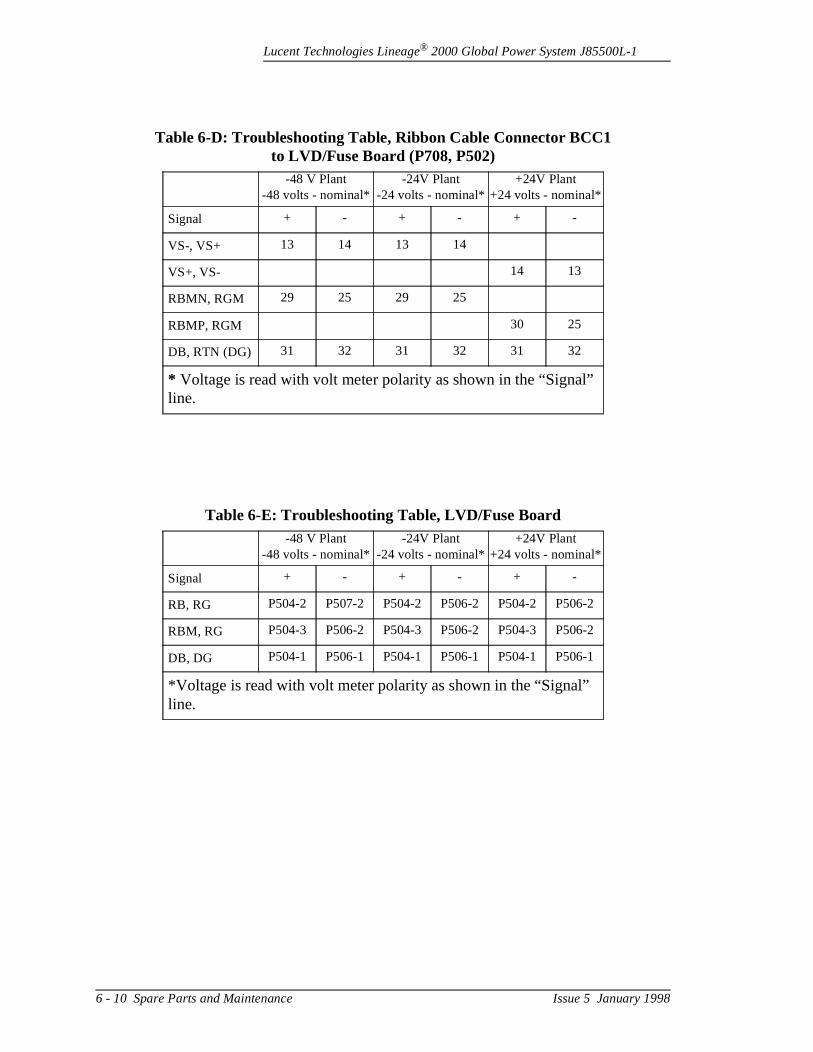
Lucent Technologies Lineage® 2000 Global Power System J85500L-1
Table 6-D: Troubleshooting Table, Ribbon Cable Connector BCC1 to LVD/Fuse Board (P708, P502)
-48 V Plant-48 volts - nominal*
-24V Plant -24 volts - nominal*
+24V Plant+24 volts - nominal*
Signal + - + - + -
VS-, VS+ 13 14 13 14
VS+, VS- 14 13
RBMN, RGM 29 25 29 25
RBMP, RGM 30 25
DB, RTN (DG) 31 32 31 32 31 32
* Voltage is read with volt meter polarity as shown in the “Signal” line.
Table 6-E: Troubleshooting Table, LVD/Fuse Board-48 V Plant
-48 volts - nominal*-24V Plant
-24 volts - nominal*+24V Plant
+24 volts - nominal*
Signal + - + - + -
RB, RG P504-2 P507-2 P504-2 P506-2 P504-2 P506-2
RBM, RG P504-3 P506-2 P504-3 P506-2 P504-3 P506-2
DB, DG P504-1 P506-1 P504-1 P506-1 P504-1 P506-1
*Voltage is read with volt meter polarity as shown in the “Signal” line.
6 - 10 Spare Parts and Maintenance Issue 5 January 1998
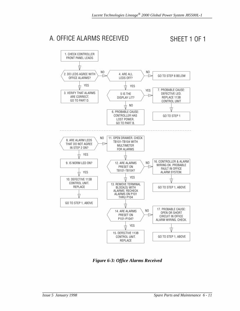
Lucent Technologies Lineage® 2000 Global Power System J85500L-1
Figure 6-3: Office Alarms Received
A. OFFICE ALARMS RECEIVED SHEET 1 OF 1
1. CHECK CONTROLLERFRONT PANEL LEADS
2. DO LEDS AGREE WITHOFFICE ALARMS?
3. VERIFY THAT ALARMSARE CORRECT.GO TO PART D.
5 IS THEDISPLAY LIT?
GO TO STEP 1
7. PROBABLE CAUSE:DEFECTIVE LED.REPLACE 113BCONTROL UNIT
6. PROBABLE CAUSE:CONTROLLER HAS
LOST POWER.GO TO PART B.
8. ARE ALARM LEDSTHAT DO NOT AGREE
IN STEP 2 ON?
9. IS NORM LED ON?
10. DEFECTIVE 113BCONTROL UNIT.
REPLACE
12. ARE ALARMSPRESET ON
TB101-TB104?
16. CONTROLLER & ALARMWIRING OK. PROBABLE
FAULT IN OFFICEALARM SYSTEM.
17. PROBABLE CAUSE:OPEN OR SHORT
CIRCUIT IN OFFICEALARM WIRING. CHECK.
14. ARE ALARMSPRESET ONP101-P104?
15. DEFECTIVE 113BCONTROL UNIT.
REPLACE
13. REMOVE TERMINALBLOCK(S) WITH
ALARMS. RECHECKALARMS ON P101
THRU P104
GO TO STEP 1, ABOVE
GO TO STEP 1, ABOVE
GO TO STEP 1, ABOVE
NO
YES
YES
YES
NO
NO
YES
11. OPEN DRAWER. CHECKTB101-TB104 WITH
MULTIMETERFOR ALARMS
NO
YES YES
YES
NO4. ARE ALLLEDS OFF?
GO TO STEP 8 BELOWNO
Issue 5 January 1998 Spare Parts and Maintenance 6 - 11
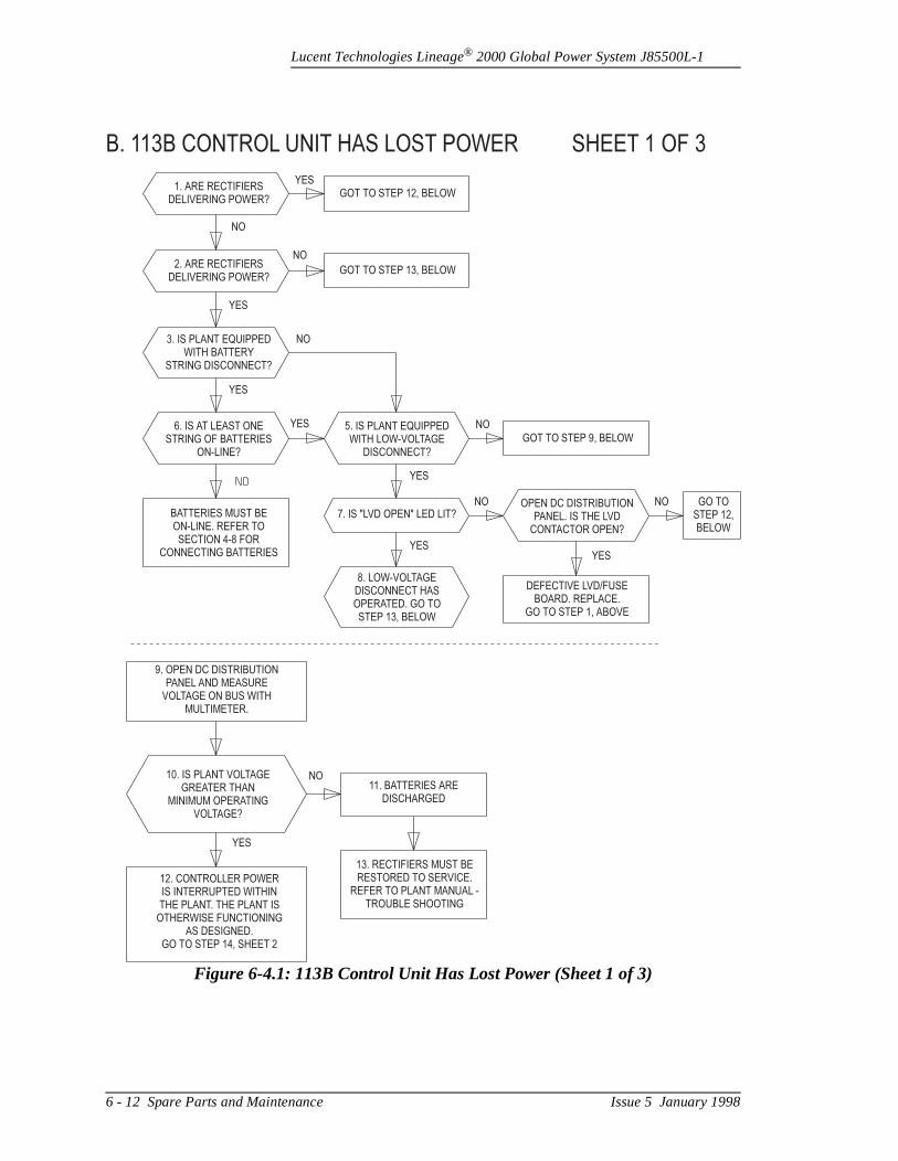
Lucent Technologies Lineage® 2000 Global Power System J85500L-1
Figure 6-4.1: 113B Control Unit Has Lost Power (Sheet 1 of 3)
B. 113B CONTROL UNIT HAS LOST POWER SHEET 1 OF 3
1. ARE RECTIFIERS
DELIVERING POWER?
2. ARE RECTIFIERS
DELIVERING POWER?
3. IS PLANT EQUIPPED
WITH BATTERY
STRING DISCONNECT?
6. IS AT LEAST ONE
STRING OF BATTERIES
ON-LINE?
BATTERIES MUST BE
ON-LINE. REFER TO
SECTION 4-8 FOR
CONNECTING BATTERIES
5. IS PLANT EQUIPPED
WITH LOW-VOLTAGE
DISCONNECT?
7. IS "LVD OPEN" LED LIT?
8. LOW-VOLTAGE
DISCONNECT HAS
OPERATED. GO TO
STEP 13, BELOW
9. OPEN DC DISTRIBUTION
PANEL AND MEASURE
VOLTAGE ON BUS WITH
MULTIMETER.
10. IS PLANT VOLTAGE
GREATER THAN
MINIMUM OPERATING
VOLTAGE?
11. BATTERIES ARE
DISCHARGED
13. RECTIFIERS MUST BE
RESTORED TO SERVICE.
REFER TO PLANT MANUAL -
TROUBLE SHOOTING
12. CONTROLLER POWER
IS INTERRUPTED WITHIN
THE PLANT. THE PLANT IS
OTHERWISE FUNCTIONING
AS DESIGNED.
GO TO STEP 14, SHEET 2
YES
NO
OPEN DC DISTRIBUTION
PANEL. IS THE LVD
CONTACTOR OPEN?
GO TO
STEP 12,
BELOW
DEFECTIVE LVD/FUSE
BOARD. REPLACE.
GO TO STEP 1, ABOVE
GOT TO STEP 13, BELOW
GOT TO STEP 9, BELOW
NO
NO NO
NO
NO
NO
YES
YES
YESYES
YES
YES
YES
GOT TO STEP 12, BELOW
6 - 12 Spare Parts and Maintenance Issue 5 January 1998
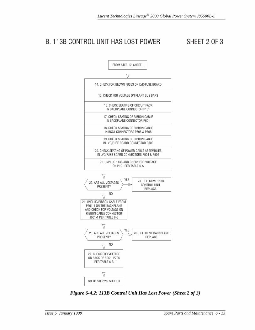
Lucent Technologies Lineage® 2000 Global Power System J85500L-1
Figure 6-4.2: 113B Control Unit Has Lost Power (Sheet 2 of 3)
B. 113B CONTROL UNIT HAS LOST POWER SHEET 2 OF 3
FROM STEP 12, SHEET 1
14. CHECK FOR BLOWN FUSES ON LVD/FUSE BOARD
15. CHECK FOR VOLTAGE ON PLANT BUS BARS
16. CHECK SEATING OF CIRCUIT PACK
IN BACKPLANE CONNECTOR P101
17. CHECK SEATING OF RIBBON CABLE
IN BACKPLANE CONNECTOR P601
18. CHECK SEATING OF RIBBON CABLE
IN BCC1 CONNECTORS P706 & P708
19. CHECK SEATING OF RIBBON CABLE
IN LVD/FUSE BOARD CONNECTOR P502
20. CHECK SEATING OF POWER CABLE ASSEMBLIES
IN LVD/FUSE BOARD CONNECTORS P504 & P506
21. UNPLUG 113B AND CHECK FOR VOLTAGE
ON P101 PER TABLE 6-A
22. ARE ALL VOLTAGES
PRESENT?
25. ARE ALL VOLTAGES
PRESENT?
27. CHECK FOR VOLTAGE
ON BACK OF BCC1, P706
PER TABLE 6-B
GO TO STEP 28, SHEET 3
26. DEFECTIVE BACKPLANE.
REPLACE.
24. UNPLUG RIBBON CABLE FROM
P601-1 ON THE BACKPLANE
AND CHECK FOR VOLTAGE ON
RIBBON CABLE CONNECTOR
J601-1 PER TABLE 6-B
23. DEFECTIVE 113B
CONTROL UNIT.
REPLACE.
YES
YES
NO
NO
Issue 5 January 1998 Spare Parts and Maintenance 6 - 13
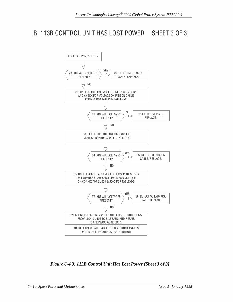
Lucent Technologies Lineage® 2000 Global Power System J85500L-1
Figure 6-4.3: 113B Control Unit Has Lost Power (Sheet 3 of 3)
B. 113B CONTROL UNIT HAS LOST POWER SHEET 3 OF 3
FROM STEP 27, SHEET 2
28. ARE ALL VOLTAGESPRESENT?
31. ARE ALL VOLTAGESPRESENT?
34. ARE ALL VOLTAGESPRESENT?
37. ARE ALL VOLTAGESPRESENT?
36. UNPLUG CABLE ASSEMBLIES FROM P504 & P506ON LVD/FUSE BOARD AND CHECK FOR VOLTAGEON CONNECTORS J504 & J506 PER TABLE 6-D
39. CHECK FOR BROKEN WIRES OR LOOSE CONNECTIONSFROM J504 & J506 TO BUS BARS AND REPAIR
OR REPLACE AS NEEDED.
40. RECONNECT ALL CABLES. CLOSE FRONT PANELSOF CONTROLLER AND DC DISTRIBUTION.
33. CHECK FOR VOLTAGE ON BACK OFLVD/FUSE BOARD P502 PER TABLE 6-C
32. DEFECTIVE BCC1.REPLACE.
29. DEFECTIVE RIBBONCABLE. REPLACE.
35. DEFECTIVE RIBBONCABLE. REPLACE.
38. DEFECTIVE LVD/FUSEBOARD. REPLACE.
YES
NO
NO
NO
NO
YES
YES
YES
30. UNPLUG RIBBON CABLE FROM P708 ON BCC1AND CHECK FOR VOLTAGE ON RIBBON CABLE
CONNECTOR J708 PER TABLE 6-C
6 - 14 Spare Parts and Maintenance Issue 5 January 1998
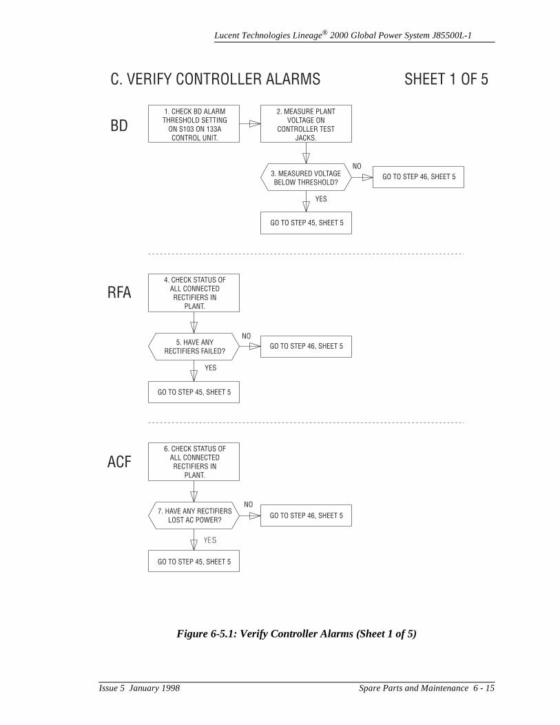
Lucent Technologies Lineage® 2000 Global Power System J85500L-1
Figure 6-5.1: Verify Controller Alarms (Sheet 1 of 5)
C. VERIFY CONTROLLER ALARMS
BD
RFA
ACF
SHEET 1 OF 5
1. CHECK BD ALARMTHRESHOLD SETTING
ON S103 ON 133ACONTROL UNIT.
4. CHECK STATUS OFALL CONNECTEDRECTIFIERS IN
PLANT.
6. CHECK STATUS OFALL CONNECTEDRECTIFIERS IN
PLANT.
5. HAVE ANYRECTIFIERS FAILED?
7. HAVE ANY RECTIFIERSLOST AC POWER?
2. MEASURE PLANTVOLTAGE ON
CONTROLLER TESTJACKS.
3. MEASURED VOLTAGEBELOW THRESHOLD?
GO TO STEP 46, SHEET 5
GO TO STEP 46, SHEET 5
GO TO STEP 46, SHEET 5
GO TO STEP 45, SHEET 5
GO TO STEP 45, SHEET 5
GO TO STEP 45, SHEET 5
NO
NO
NO
YES
YES
Issue 5 January 1998 Spare Parts and Maintenance 6 - 15
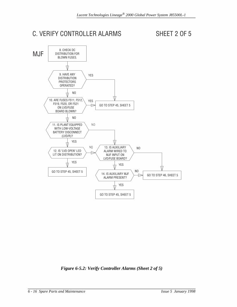
Lucent Technologies Lineage® 2000 Global Power System J85500L-1
Figure 6-5.2: Verify Controller Alarms (Sheet 2 of 5)
C. VERIFY CONTROLLER ALARMS
MJF
SHEET 2 OF 5
8. CHECK DCDISTRIBUTION FOR
BLOWN FUSES.
9. HAVE ANYDISTRIBUTIONPROTECTORSOPERATED?
10. ARE FUSES F511, F512,F519, F520, OR F521
ON LVD/FUSEBOARD BLOWN?
11. IS PLANT EQUIPPEDWITH LOW-VOLTAGE
BATTERY DISCONNECT(LVD/R)?
13. IS AUXILIARYALARM WIRED TO
MJF INPUT ONLVD/FUSE BOARD?
14. IS AUXILIARY MJFALARM PRESENT?
12. IS "LVD OPEN" LEDLIT ON DISTRIBUTION?
NO
NO
NO
NO
YES
YESYES
YES
YES
GO TO STEP 45, SHEET 5
GO TO STEP 46, SHEET 5GO TO STEP 45, SHEET 5
GO TO STEP 45, SHEET 5
YES
6 - 16 Spare Parts and Maintenance Issue 5 January 1998
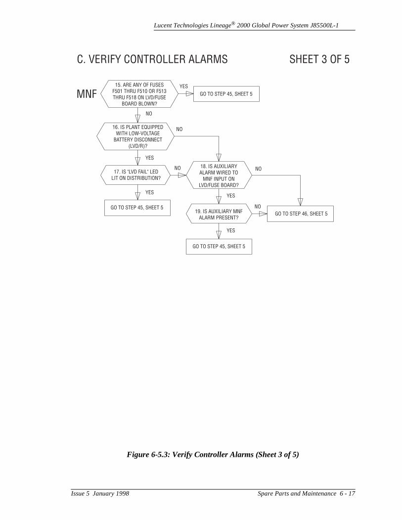
Lucent Technologies Lineage® 2000 Global Power System J85500L-1
Figure 6-5.3: Verify Controller Alarms (Sheet 3 of 5)
C. VERIFY CONTROLLER ALARMS
MNF
SHEET 3 OF 5
15. ARE ANY OF FUSESF501 THRU F510 OR F513THRU F518 ON LVD/FUSE
BOARD BLOWN?
16. IS PLANT EQUIPPEDWITH LOW-VOLTAGE
BATTERY DISCONNECT(LVD/R)?
17. IS "LVD FAIL" LEDLIT ON DISTRIBUTION?
18. IS AUXILIARYALARM WIRED TO
MNF INPUT ONLVD/FUSE BOARD?
19. IS AUXILIARY MNFALARM PRESENT?
GO TO STEP 45, SHEET 5
GO TO STEP 45, SHEET 5
GO TO STEP 45, SHEET 5
GO TO STEP 46, SHEET 5
YES
YES
YESYES
YES
NO
NONO
NO
NO
Issue 5 January 1998 Spare Parts and Maintenance 6 - 17
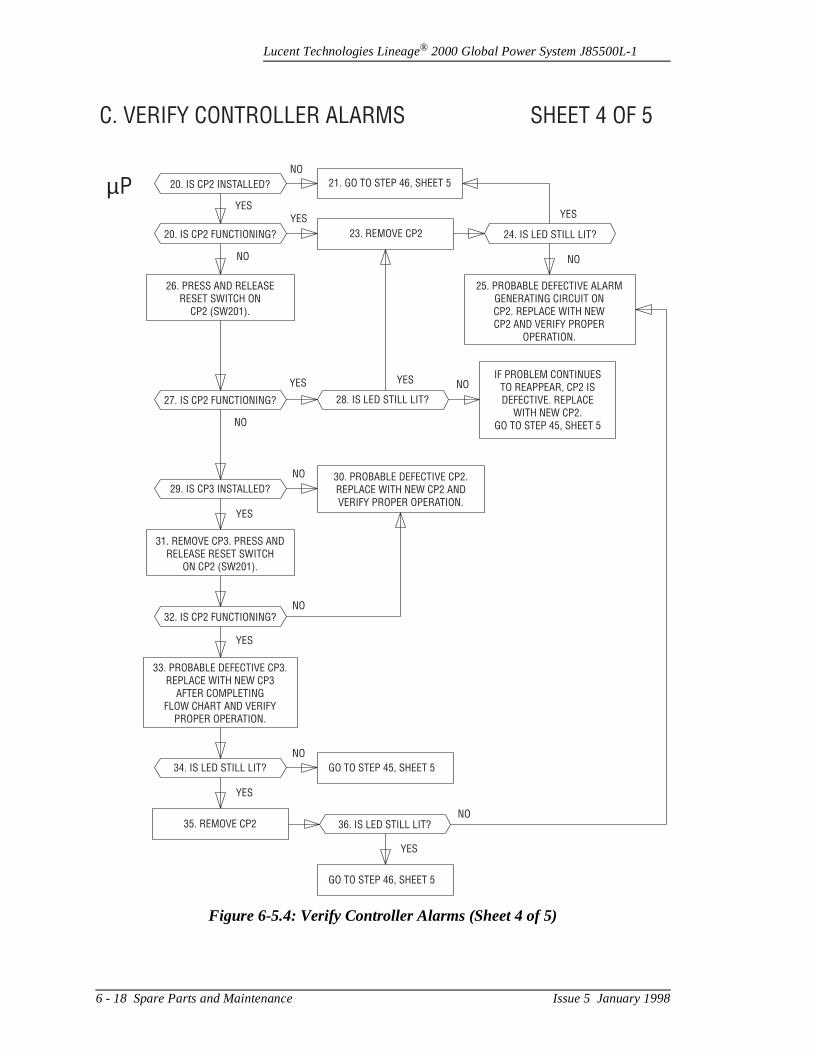
Lucent Technologies Lineage® 2000 Global Power System J85500L-1
Figure 6-5.4: Verify Controller Alarms (Sheet 4 of 5)
C. VERIFY CONTROLLER ALARMS
µP
SHEET 4 OF 5
20. IS CP2 INSTALLED?
NO
NO NO
NO
NO
NO
NO
NO
NO
YESYES
YES
YES
YES
YES
YESYES
YES
20. IS CP2 FUNCTIONING?
26. PRESS AND RELEASERESET SWITCH ON
CP2 (SW201).
25. PROBABLE DEFECTIVE ALARMGENERATING CIRCUIT ONCP2. REPLACE WITH NEWCP2 AND VERIFY PROPER
OPERATION.
IF PROBLEM CONTINUESTO REAPPEAR, CP2 ISDEFECTIVE. REPLACE
WITH NEW CP2.GO TO STEP 45, SHEET 5
27. IS CP2 FUNCTIONING?
32. IS CP2 FUNCTIONING?
33. PROBABLE DEFECTIVE CP3.REPLACE WITH NEW CP3
AFTER COMPLETINGFLOW CHART AND VERIFY
PROPER OPERATION.
29. IS CP3 INSTALLED?
31. REMOVE CP3. PRESS ANDRELEASE RESET SWITCH
ON CP2 (SW201).
30. PROBABLE DEFECTIVE CP2.REPLACE WITH NEW CP2 ANDVERIFY PROPER OPERATION.
21. GO TO STEP 46, SHEET 5
23. REMOVE CP2 24. IS LED STILL LIT?
28. IS LED STILL LIT?
34. IS LED STILL LIT?
36. IS LED STILL LIT?35. REMOVE CP2
GO TO STEP 45, SHEET 5
GO TO STEP 46, SHEET 5
6 - 18 Spare Parts and Maintenance Issue 5 January 1998
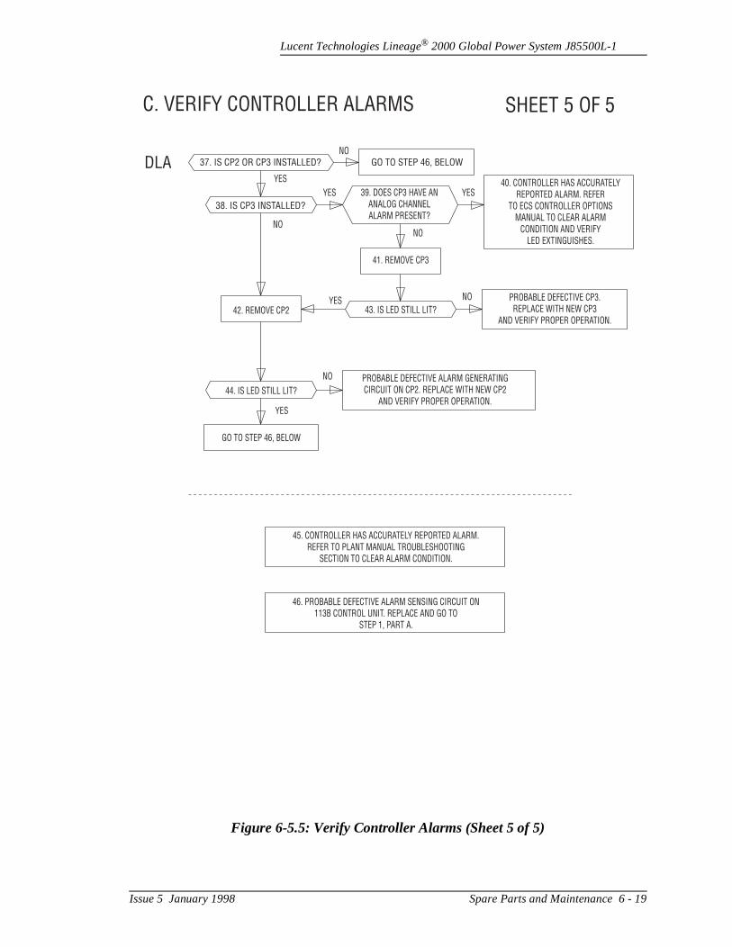
Lucent Technologies Lineage® 2000 Global Power System J85500L-1
Figure 6-5.5: Verify Controller Alarms (Sheet 5 of 5)
C. VERIFY CONTROLLER ALARMS
DLA
SHEET 5 OF 5
37. IS CP2 OR CP3 INSTALLED?
38. IS CP3 INSTALLED?
GO TO STEP 46, BELOW
39. DOES CP3 HAVE ANANALOG CHANNELALARM PRESENT?
41. REMOVE CP3
43. IS LED STILL LIT?
44. IS LED STILL LIT?
GO TO STEP 46, BELOW
PROBABLE DEFECTIVE CP3.REPLACE WITH NEW CP3
AND VERIFY PROPER OPERATION.
PROBABLE DEFECTIVE ALARM GENERATINGCIRCUIT ON CP2. REPLACE WITH NEW CP2
AND VERIFY PROPER OPERATION.
45. CONTROLLER HAS ACCURATELY REPORTED ALARM.REFER TO PLANT MANUAL TROUBLESHOOTING
SECTION TO CLEAR ALARM CONDITION.
46. PROBABLE DEFECTIVE ALARM SENSING CIRCUIT ON113B CONTROL UNIT. REPLACE AND GO TO
STEP 1, PART A.
YES
YES YES
YES
YES
NO
NO
NONO
NO
42. REMOVE CP2
40. CONTROLLER HAS ACCURATELYREPORTED ALARM. REFER
TO ECS CONTROLLER OPTIONSMANUAL TO CLEAR ALARM
CONDITION AND VERIFYLED EXTINGUISHES.
Issue 5 January 1998 Spare Parts and Maintenance 6 - 19
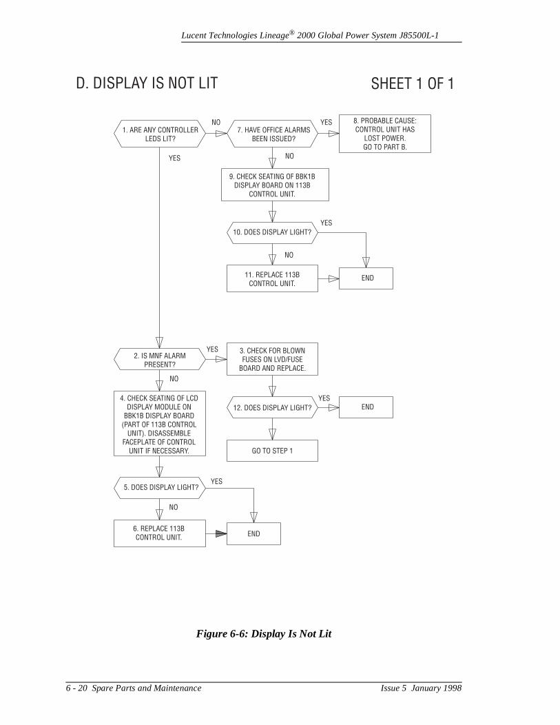
Lucent Technologies Lineage® 2000 Global Power System J85500L-1
Figure 6-6: Display Is Not Lit
D. DISPLAY IS NOT LIT SHEET 1 OF 1
1. ARE ANY CONTROLLERLEDS LIT?
7. HAVE OFFICE ALARMSBEEN ISSUED?
8. PROBABLE CAUSE:CONTROL UNIT HAS
LOST POWER.GO TO PART B.
9. CHECK SEATING OF BBK1BDISPLAY BOARD ON 113B
CONTROL UNIT.
10. DOES DISPLAY LIGHT?
11. REPLACE 113BCONTROL UNIT.
6. REPLACE 113BCONTROL UNIT.
2. IS MNF ALARMPRESENT?
3. CHECK FOR BLOWNFUSES ON LVD/FUSE
BOARD AND REPLACE.
12. DOES DISPLAY LIGHT?
GO TO STEP 1
5. DOES DISPLAY LIGHT?
4. CHECK SEATING OF LCDDISPLAY MODULE ON
BBK1B DISPLAY BOARD(PART OF 113B CONTROL
UNIT). DISASSEMBLEFACEPLATE OF CONTROL
UNIT IF NECESSARY.
END
END
END
NO
NO
NO
NO
YES
YES
YES
YES
YES
YES NO
6 - 20 Spare Parts and Maintenance Issue 5 January 1998
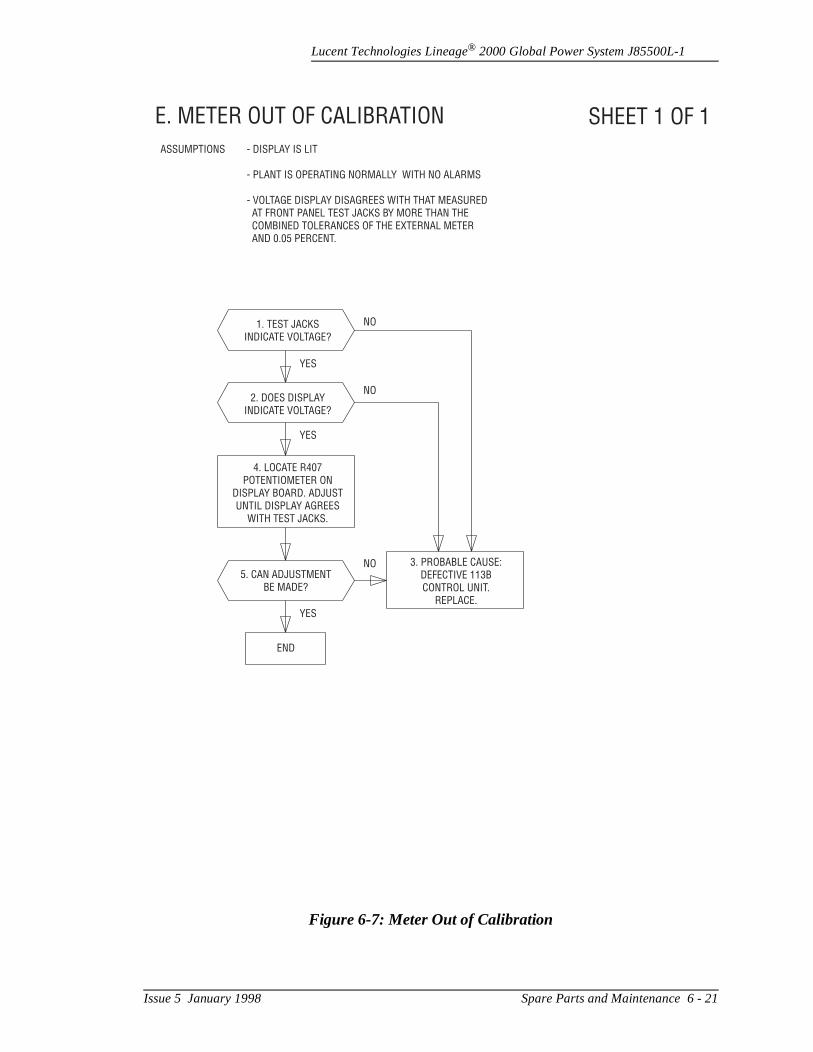
Lucent Technologies Lineage® 2000 Global Power System J85500L-1
Figure 6-7: Meter Out of Calibration
E. METER OUT OF CALIBRATION SHEET 1 OF 1
1. TEST JACKSINDICATE VOLTAGE?
ASSUMPTIONS - DISPLAY IS LIT
- PLANT IS OPERATING NORMALLY WITH NO ALARMS
- VOLTAGE DISPLAY DISAGREES WITH THAT MEASUREDAT FRONT PANEL TEST JACKS BY MORE THAN THECOMBINED TOLERANCES OF THE EXTERNAL METERAND 0.05 PERCENT.
2. DOES DISPLAYINDICATE VOLTAGE?
5. CAN ADJUSTMENTBE MADE?
END
3. PROBABLE CAUSE:DEFECTIVE 113BCONTROL UNIT.
REPLACE.
NO
NO
NO
YES
YES
YES
4. LOCATE R407POTENTIOMETER ON
DISPLAY BOARD. ADJUSTUNTIL DISPLAY AGREES
WITH TEST JACKS.
Issue 5 January 1998 Spare Parts and Maintenance 6 - 21
Lucent Technologies Lineage® 2000 Global Power System J85500L-1
is one
P5
.
to
Low Voltage Disconnect Circuitry
Red LVD OPENLED Lit
The Red LVD OPEN LED indicates that the LVD Contactor de-energized, i.e., open. The contactor may be open due toof four reasons:
1. Plant voltage is below the disconnect threshold.
2. The contactor has failed and must be replaced. See procedure below.
3. There is an open circuit in the wiring that powers the contactor. Check the cable assembly from CP5 to the contactor (see drawing T-83167-30).
4. Both redundant LVD sensing circuits have failed. The Ccircuit pack must be replaced. Follow “LVD/Fuse Board(CP5) Replacement Procedure.”
Yellow LVDFAIL LED Lit
The Yellow LVD FAIL LED indicates that one or both of the LVD circuits has attempted to open the contactor, but the contactor is closed. This may occur in two situations.
1. The plant voltage is right at the disconnect level and is within tolerances of the redundant detector circuits, but only one detector has operated. No action is required.
2. The LVD circuit has partially failed. Follow the “LVD/R Fuse Board (CP5) Fuse Board Replacement” procedure
LVD/Fuse Board(CP5)
ReplacementProcedure
A standard screwdriver is required for this procedure. (ReferFigure 2-13 and T-83167-30 drawing)
1. Open distribution panel.
6 - 22 Spare Parts and Maintenance Issue 5 January 1998

Lucent Technologies Lineage® 2000 Global Power System J85500L-1
se
ss
e
2. Unplug the following connectors from the LVD/Fuse Board (CP5). Leave the cables dressed.
– J502 from P502– J508 from P508– J506 from P506– J501 from P501– J504 from P504– Wires from TB501
3. Remove the 6 mounting screws.
4. Set jumpers J505.1 and J505.2 on replacement LVD/FuBoard (CP5), in the same positions as on the defective CP5, for the correct disconnect voltage.
5. Mount the replacement board to the distribution panel using the hardware from Step 3.
6. Reconnect the following connectors:
– J502 to P502– J508 to 508– J506 to P506– J501 to P501– J504 to P504– Wires to TB501
7. Close distribution panel.
LVD/RContactor
Replacement
Verify the following:
• Contactor coil has failed.• The contactor is open.• The rectifiers are carrying the load (off battery) with exce
capacity available for charging the batteries.• Battery string(s) are at a voltage below the rectifier voltag
in a state of partial or complete discharge.• LVD OPEN LED is lit on the distribution front panel.
Issue 5 January 1998 Spare Parts and Maintenance 6 - 23

Lucent Technologies Lineage® 2000 Global Power System J85500L-1
en
ify
d
Required Equipment:
– socket wrench with insulated handle– M13 socket
Procedure: (Refer to Figure 2-16 and T-83167-30 drawing)
1. Remove rectifier in position directly beneath LVD/R contactor (position 1), if present.
2. Open LVD/fuse panel door and unplug connector P501from J501 on LVD/Fuse Board (CP5). Leave cable dressed.
3. Disconnect and label the 5 quick connects from the contactor coil and auxiliary switch.
4. Unbolt and remove contactor (6 places).
5. Reconnect quick connect leads to new contactor and thmount new contactor using hardware from Step 4.
6. Plug P501 into J501 on LVD/Fuse Board (CP5) and verthat contactor closes.
7. Replace rectifier and turn on.
8. Close LVD/fuse panel door and verify that LVD FAIL anLVD OPEN lights are not lit.
6 - 24 Spare Parts and Maintenance Issue 5 January 1998

Lucent Technologies Lineage® 2000 Global Power System J85500L-1
the title
ch
ies of
e if r's e f
cts
7 Product Warranty
A. Seller warrants to Customer only, that:
1. As of the date title to Products passes, Seller will have right to sell, transfer, and assign such Products and the conveyed by Seller shall be good;
2. Upon shipment, Seller’s Manufactured Products will befree from defects in material and workmanship, and willconform to Seller’s specifications or any other agreed-upon specification referenced in the order for suProduct;
3. With respect to Vendor items, Seller, to the extent permitted, does hereby assign to Customer the warrantgiven to Seller by its Vendor of such Vendor Items, suchassignment to be effective upon Customer’s acceptancesuch Vendor Items. With respect to Vendor items recommended by Seller in its specifications for which thVendor's warranty cannot be assigned to Customer, or assigned, less than Sixty (60) days remain of the Vendowarranty or warranty period when the Vendor's items arshipped to Customer or when Seller submits its notice ocompletion of installation if installed by Seller, Seller warrants that such Vendor's items will be free from defein material and workmanship on the date of shipment toCustomer. In such an event, the applicable Warranty Period will be sixty (60) days.
B. The Warranty Period listed below is applicable to Seller’sManufactured Products furnished pursuant to this Agreement, unless otherwise stated:
Issue 5 January 1998 Product Warranty 7 - 1

Lucent Technologies Lineage® 2000 Global Power System J85500L-1
a
rs
g or t
ler. ed duct
y ily
cts
uct, ng
o
e tore be s nse
d
tial
C. If, under normal and proper use during the applicable Warranty Period, a defect or nonconformity is identified inProduct and Customer notifies Seller in writing of such defect or nonconformity promptly after Customer discovesuch defect or nonconformity, and follows Seller's instructions regarding return of defective or nonconforminProducts, Seller shall, at its option attempt first to repair replace such Product without charge at its facility or, if nofeasible, provide a refund or credit based on the original purchase price and installation charges if installed by SelWhere Seller has elected to repair a Seller’s ManufacturProduct (other than Cable and Wire Products) which hasbeen installed by Seller and Seller ascertains that the Prois not readily returnable for repair, Seller will repair the Product at Customer’s site.
With respect to Cable and Wire Products manufactured bSeller which Seller elects to repair but which are not readreturnable for repair, whether or not installed by Seller, Seller at its option, may repair the cable and Wire Produat Customer’s site.
D. If Seller has elected to repair or replace a defective ProdCustomer shall have the option of removing and reinstallior having Seller remove and reinstall the defective or nonconforming Product. The cost of the removal and thereinstallation shall be borne by Customer. With respect tCable and Wire Products, Customer has the further responsibility, at its expense, to make the Cable and WirProducts accessible for repair or replacement and to resthe site. Products returned for repair or replacement will accepted by Seller only in accordance with its instructionand procedures for such returns. The transportation expe
Warranty Period
Product Type New ProductRepaired Product
or Part*
Central Office Power Equipment**
24 Months 6 Months
* The Warranty Period for a repaired Product or part thereof is as listeor, in the case of Products under Warranty, is the period listed or theunexpired term of the new Product Warranty Period, whichever is longer.
** The Warranty Period for Products ordered for Use in Systems or equipment Manufactured by and furnished by Seller is that of the iniSystems or equipment.
7 - 2 Product Warranty Issue 5 January 1998

Lucent Technologies Lineage® 2000 Global Power System J85500L-1
tion
are
g, d
any or
t in
s.
nd t
associated with returning such Product to Seller shall beborne by Customer. Seller shall pay the cost of transportaof the repair or replacing Product to the destination designated by Customer within the Territory.
E. The defective or nonconforming Products or parts which replaced shall become Seller's property.
F. If Seller determines that a Product for which warranty service is claimed is not defective or nonconforming, Customer shall pay Seller all costs of handling, inspectintesting, and transportation and, if applicable, traveling anrelated expenses.
G. Seller makes no warranty with respect to defective conditions or nonconformities resulting from actions of anyone other than Seller or its subcontractors, caused byof the following: modifications, misuse, neglect, accident, abuse; improper wiring, repairing, splicing, alteration, installation, storage, or maintenance; use in a manner noaccordance with Seller’s or Vendor’s specifications or operating instructions, or failure of Customer to apply previously applicable Seller modifications and correctionIn addition, Seller makes no warranty with respect to Products which have had their serial numbers or month ayear of manufacture removed, altered, or with respect toexpendable items, including, without limitation, fuses, lighbulbs, motor brushes, and the like.
THE FOREGOING WARRANTIES ARE EXCLUSIVE AND ARE IN LIEU OF ALL OTHER EXPRESS AND IMPLIED WARRANTIES, INCLUDING BUT NOT LIMITED TO WARRANTIES OF MERCHANTABILITY AND FITNESS FOR A PARTICULAR PURPOSE. CUSTOMER’S SOLE AND EXCLUSIVE REMEDY SHALL BE SELLER’S OBLIGATION TO REPAIR, REPLACE, CREDIT, OR REFUND AS SET FORTH ABOVE IN THIS WARRANTY.
Issue 5 January 1998 Product Warranty 7 - 3