Limpet System Installation Proposal · Rev.01B Page 2 of 37 Limpet Technology Limited, 5/2 Mitchell...
37
Rev.01B Page 1 of 37 Limpet Technology Limited, 5/2 Mitchell Street, Leith, Edinburgh, EH6 7BD Tel: +44 (0)131 551 2727 Email: [email protected] Web: www.limpettechnology.com Company registered in Scotland No. SC 357375 Limpet ® System Installation Proposal Rev 01.B Installation of the Limpet ® Multifunctional Height Safety System CONFIDENTIAL Summary On the (date), engineers from Limpet Technology Ltd. carried out a pre-installation survey of a (make and model) wind turbine at (site, country). Onsite they surveyed Wind Turbine Generator (WTG) 1 and identified an installation solution for the Limpet ® multifunctional height safety system. The Limpet ® would provide fall prevention, 90% climb assist, evacuation, remote rescue and work positioning on the main ladder. The following document provides technical details of the installation for a single Limpet ® system. Customer: Date: Site:
Transcript of Limpet System Installation Proposal · Rev.01B Page 2 of 37 Limpet Technology Limited, 5/2 Mitchell...

Rev.01B Page 1 of 37
Limpet Technology Limited, 5/2 Mitchell Street, Leith, Edinburgh, EH6 7BD
Tel: +44 (0)131 551 2727 Email: [email protected] Web: www.limpettechnology.com
Company registered in Scotland No. SC 357375
Limpet® System Installation Proposal
Rev 01.B
Installation of the Limpet® Multifunctional Height Safety System
CONFIDENTIAL
Summary
On the (date), engineers from Limpet Technology Ltd. carried out a pre-installation survey of a
(make and model) wind turbine at (site, country). Onsite they surveyed Wind Turbine Generator
(WTG) 1 and identified an installation solution for the Limpet® multifunctional height safety
system. The Limpet® would provide fall prevention, 90% climb assist, evacuation, remote
rescue and work positioning on the main ladder.
The following document provides technical details of the installation for a single Limpet®
system.
Customer:
Date:
Site:

Rev.01B Page 2 of 37
Limpet Technology Limited, 5/2 Mitchell Street, Leith, Edinburgh, EH6 7BD
Tel: +44 (0)131 551 2727 Email: [email protected] Web: www.limpettechnology.com
Company registered in Scotland No. SC 357375
Table of Contents
1 Introduction ......................................................................................................................................... 5
1.1 Background ................................................................................................................................. 5
1.2 Aims and Objectives .................................................................................................................. 5
2 Site Survey Details .............................................................................................................................. 6
2.1 Internal WTG Configuration ...................................................................................................... 6
3 Installation ........................................................................................................................................... 8
3.1 Summary ..................................................................................................................................... 8
3.2 The Limpet® System ................................................................................................................ 12
3.3 Mechanical Installation ........................................................................................................... 13
3.3.1 Limpet® .............................................................................................................................. 13
3.3.2 Uninterruptable Power Supply ....................................................................................... 14
3.3.3 Single Limpet® Head Pulley Structure .......................................................................... 15
3.3.4 Control Units ..................................................................................................................... 16
3.3.5 Safety Line Return ........................................................................................................... 17
3.3.6 Safety hatches .................................................................................................................. 17
3.4 Electrical Installation ............................................................................................................... 18
3.4.1 Power Supply .................................................................................................................... 18
3.4.2 Wired Control Units .......................................................................................................... 18
3.4.3 Wireless RF Remote ........................................................................................................ 18
3.5 Wall Notices .............................................................................................................................. 18
4 Design of New Structural Elements ............................................................................................... 19
4.1 Limpet® Mounting Structure ................................................................................................... 19
4.2 Head Pulley Structure .............................................................................................................. 22
5 Comparison of Forces on Ladder ................................................................................................... 25
5.1 Summary ................................................................................................................................... 25
5.2 Forces on Ladder for Ladder-Mounted Limpet® .................................................................. 25

Rev.01B Page 3 of 37
Limpet Technology Limited, 5/2 Mitchell Street, Leith, Edinburgh, EH6 7BD
Tel: +44 (0)131 551 2727 Email: [email protected] Web: www.limpettechnology.com
Company registered in Scotland No. SC 357375
5.3 Forces on Ladder for Floor-Mounted Limpet® ...................................................................... 27
6 Installation Method Statement and Risk Assessment ............................................................... 29
7 Certification Details .......................................................................................................................... 30
7.1 Limpet® System ........................................................................................................................ 30
7.2 Uninterruptable Power Supply ............................................................................................... 31
7.3 Wireless Remote Control ........................................................................................................ 31
8 Appendix A – Limpet® Mounting Structure .................................................................................. 32
9 Appendix B – Limpet® Bolts ............................................................................................................ 34
10 Appendix C – Head Pulley Structure .............................................................................................. 35
Rev.01B Page 4 of 37
Limpet Technology Limited, 5/2 Mitchell Street, Leith, Edinburgh, EH6 7BD
Tel: +44 (0)131 551 2727 Email: [email protected] Web: www.limpettechnology.com
Company registered in Scotland No. SC 357375
Table of Figures
Figure 1: Schematic of turbine layout showing; the single ladder configuration in grey, L1, and
four internal platforms including the yaw floor. ..................................................................................... 7
Figure 2: CAD representation of Limpet® height safety proposal showing; (make and model)
third platform, the Limpet® main unit, UPS and Ladder Mounting Structure (cable conduit
hidden for clarity) ........................................................................................................................................ 9
Figure 3: CAD representation of Limpet® height safety proposal showing; (make and model) yaw
platform, the Limpet® Safety Line path, Head Pulley Location, and Line Return Wire ................. 10
Figure 4: Yaw floor detail showing rollers for edge protection (ladder and HACA rail hidden for
clarity) ......................................................................................................................................................... 11
Figure 5: Exploded assembly showing the ladder-mounted Limpet® ............................................... 13
Figure 6: CAD image of the yaw platform showing the safety line path up to the head pulley
structure. .................................................................................................................................................... 14
Figure 7: CAD model showing the Limpet® head pulley clamped to the Limpet® cross-member.
The Limpet® pulley is mounted on the LHS to minimise fowling with the HACA rail. .................... 16
Figure 8: CAD render of Limpet® ladder mounting structure ............................................................. 19
Figure 9: Von Mises stresses (left) and displacement (right) in side plate of ladder mounting
bracket. ....................................................................................................................................................... 20
Figure 10: Von Mises stresses in horizontal member of ladder mounting bracket. Maximum
stress = 117.6MPa ................................................................................................................................... 21
Figure 11: Displacement in horizontal member of ladder mounting bracket. Maximum
displacement = 0.21mm ......................................................................................................................... 21
Figure 12: CAD Render of head pulley structure and ladder. ............................................................ 22
Figure 13: Von Mises stresses in pulley structure. Maximum stress = 250.3MPa ........................ 23
Figure 14: Displacement in pulley structure. Maximum displacement = 1.32mm ....................... 24
Figure 15: Ladder mounted Limpet® and maximum and ultimate force in line ............................ 25
Figure 16: Forces on head pulley and ladder for ladder mounted Limpet® .................................... 26
Figure 17: Alternative Limpet® mounting solution on third floor ...................................................... 27
Figure 18: Resultant force on ladder with alternative arrangement ................................................ 28

Rev.01B Page 5 of 37
Limpet Technology Limited, 5/2 Mitchell Street, Leith, Edinburgh, EH6 7BD
Tel: +44 (0)131 551 2727 Email: [email protected] Web: www.limpettechnology.com
Company registered in Scotland No. SC 357375
1 Introduction
1.1 Background
The Limpet® is the world’s only integrated fall protection, climb assist, rescue, evacuation and
work positioning system; a total height safety solution that provides five key functions in one
simple, reliable and cost-effective system. The Limpet's climb assist function increases
productivity and reduces expensive downtime, while its “always-on” fall prevention technology
prevents the accidents that cost lives, money and reputation. Combined with market-leading
rescue, evacuation and work-positioning technology, reduced maintenance and servicing
requirements, and a minimum 25-year lifespan, the Limpet® offers significant cost of
ownership benefits.
1.2 Aims and Objectives
The purpose of the onsite survey was to allow Limpet® engineers to assess the suitability of
providing a total height safety solution to (customer name and site) wind farm, (country). This
involved evaluating conventional ladder access to the nacelle, identifying an appropriate
installation platform for the Limpet® unit and suitable safety line path, appropriate power
supply and location for correct Limpet® operation, and installation compatibility with respect to
the OEM design and fall arrest systems already in situ. For each installation, Limpet® work to
exceed all current safety standards and specific company directives, supporting employers'
corporate responsibilities.

Rev.01B Page 6 of 37
Limpet Technology Limited, 5/2 Mitchell Street, Leith, Edinburgh, EH6 7BD
Tel: +44 (0)131 551 2727 Email: [email protected] Web: www.limpettechnology.com
Company registered in Scotland No. SC 357375
2 Site Survey Details
On the (date), engineers from Limpet Technology Ltd. carried out a pre-installation survey of
WTG 1, a (make and model) turbine on the (owner and site and country). The following sections
record the site findings and describe, in detail, the installation proposal for a single Limpet®
system and line return.
2.1 Internal WTG Configuration
The (make and model) turbine has an approximate hub height of XXm. Inside, there is a single
ladder used by personnel to gain access to the nacelle, where this is the only method of access.
The ladder (L1) measures a distance of ~xxm between the ground floor and the yaw platform.
There are four platforms, including the yaw floor, as shown schematically in Figure 1. All
platforms are protected with hinged aluminium chequered plate hatches. Each floor (with the
exception of the yaw floor) consists of fabricated steel chequered panels, thickness 6mm,
where the floor is stiffened by steel ribs welded and bolted on the underside and at the
perimeter to bosses welded to the turbine wall. The yaw floor is constructed from fully welded
6-7mm steel sheet and is also fully welded around it’s perimeter to the turbine wall. The
Limpet® system would provide fall prevention, 90% climb assist, evacuation and rescue
functionality on L1.
A HACA fixed rail (EN 353-1 type) fall arrest system is installed on L1, where the nominal ladder
width is 490mm. The HACA rail runs down the centre of the ladder, therefore the Limpet® head
pulley structure would be installed asymmetrically, permitting the Limpet® safety line to run
down either to the left or the right of the rail. The Limpet® has been installed successfully
alongside similar guided systems.
The main access ladder (L1) extends ~1.1m above the yaw platform and the base of the nacelle
ladder measures ~1.4m above the platform. The nacelle ladder is mounted off the nacelle and
yaws around the yaw ring. The dimensional arrangement of the main and nacelle ladder dictate
that the maximum height of any Limpet designed pulley structure above the main ladder must
be less than 0.3m, although this dimension can be turbine specific. Should this dimension be
exceeded then the nacelle ladder would impinge on the pulley structure during yaw.

Rev.01B Page 7 of 37
Limpet Technology Limited, 5/2 Mitchell Street, Leith, Edinburgh, EH6 7BD
Tel: +44 (0)131 551 2727 Email: [email protected] Web: www.limpettechnology.com
Company registered in Scotland No. SC 357375
Figure 1: Schematic of turbine layout showing; the single ladder configuration in grey, L1, and four internal
platforms including the yaw floor.
The yaw platform measures ~3m in diameter and in the centre a steel stanchion frame allows
operatives to step up and onto the nacelle ladder. This third platform also measures ~3m in
diameter and has two cable conduits running through it. To avoid restricting the working space
available on the yaw platform, the simplest installation arrangement would be to mount the
Limpet® off the ladder on the third floor.
Ground Floor
First Floor
Second Floor
Third Floor
Yaw Floor
L1

Rev.01B Page 8 of 37
Limpet Technology Limited, 5/2 Mitchell Street, Leith, Edinburgh, EH6 7BD
Tel: +44 (0)131 551 2727 Email: [email protected] Web: www.limpettechnology.com
Company registered in Scotland No. SC 357375
3 Installation
This section describes a single Limpet® system retrofit into a (make and model of wind turbine).
The Limpet® will be installed to provide access protection to the entire ladder length.
3.1 Summary
The Limpet® unit will be mounted off the back of the main access ladder on the third platform
(Figure 2). The position of the Limpet® ensures that operatives are not restricted when
accessing the yaw room to gain access to the nacelle. The safety line1 will exit the Limpet® and
will pass straight up the back of the ladder to a head pulley mounted off Limpet’s installation
framework (Figure 3). New Limpet® metalwork has been designed to fit alongside the existing
HACA fall arrest system and is capable of withstanding a 20kN safety line load to comply with
EN50308 (anchor load rating during evacuation). The framework provides a convenient load
bearing point, satisfying both the load requirements and the practical requirements to allow
users to step safely off the ladder, whilst still maintaining access to the nacelle ladder. The
height of the pulley above the floor has been designed to maximise the distance between the
floor and the operative’s sternum attachment point, allowing the user to climb through the
hatchway and close the cover before disconnecting from the Limpet®. The Limpet® will be
supplied on mounting rails which will be fastened to the ladder using a Limpet® designed
mounting frame. The three closest ladder rungs will be reinforced with M16 threaded bar and
two steel side plates, to provide extra stiffness.
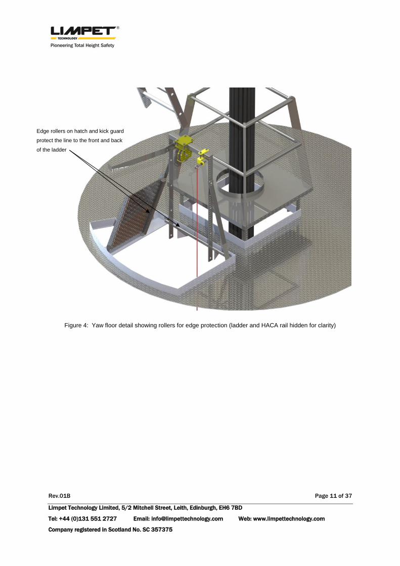
All safety hatches will remain to protect the user when accessing intermediate platforms and
the nacelle, and during entry/egress to the Limpet® system. The front of all hatches (and any
other potentially abrasive surfaces) will be fitted with a means of edging protection, such as a
small roller to eliminate safety line abrasion (Figure 4). The yaw deck hatch will be replaced
with a specifically designed hatch to compliment the head pulley metalwork.
A single-phase 230V, minimum 14A supply is required to power the Limpet®, via a standard
Limpet® uninterruptable power supply (UPS). The UPS typically provides forty minutes of battery
operation should mains power be interrupted. The UPS will be securely located on anti-vibration
feet and positioned adjacent to the Limpet®.
1 Dyneema® core with a Technora® sheath, MBL 29.4kN, or Dyneema® core with Polyester sheath MBL 24kN.

Rev.01B Page 9 of 37
Limpet Technology Limited, 5/2 Mitchell Street, Leith, Edinburgh, EH6 7BD
Tel: +44 (0)131 551 2727 Email: [email protected] Web: www.limpettechnology.com
Company registered in Scotland No. SC 357375
There is a 230Vac socket available on the third floor, to the left hand side of the ladder (when
climbing). Should power be made available from this location, the Limpet® may be plugged
straight in using a short 2m length of cable. The cable specification for the Limpet® mains
supply is standard 3-core H07RNF cable, 1.5sq.mm and would be terminated with a standard
plug.
Control units for the Limpet® system will be placed at the yaw platform and bottom of the main
access ladder (L1). These will be accessible to the operative without obstructing access/egress
to the ladder.
Figure 2: CAD representation of Limpet® height safety proposal showing; third platform, the Limpet
® main unit,
UPS and Ladder Mounting Structure (cable conduit hidden for clarity)
Limpet® mounted off the
reinforced ladder and mounting
structure
UPS mounted on anti-
vibration mounting feet,
located below the Limpet®
Ladder mounting structure

Rev.01B Page 10 of 37
Limpet Technology Limited, 5/2 Mitchell Street, Leith, Edinburgh, EH6 7BD
Tel: +44 (0)131 551 2727 Email: [email protected] Web: www.limpettechnology.com
Company registered in Scotland No. SC 357375
Figure 3: CAD representation of Limpet®
height safety proposal showing; yaw platform, the Limpet® Safety Line
path, Head Pulley Location, and Line Return Wire
Voltage cables
HACA rail bolted to
centre of ladder L1
Access hatch with edging
protection (shown open with
small roller)
Line return guide (red)
runs down RHS of ladder
Head Pulley clamped around
supporting Limpet® metalwork
Nacelle ladder (shown directly
over main access ladder)
continues up to nacelle
Safety line path
(shown in blue)
Rev.01B Page 11 of 37
Limpet Technology Limited, 5/2 Mitchell Street, Leith, Edinburgh, EH6 7BD
Tel: +44 (0)131 551 2727 Email: [email protected] Web: www.limpettechnology.com
Company registered in Scotland No. SC 357375
Figure 4: Yaw floor detail showing rollers for edge protection (ladder and HACA rail hidden for clarity)
Edge rollers on hatch and kick guard
protect the line to the front and back
of the ladder

Rev.01B Page 12 of 37
Limpet Technology Limited, 5/2 Mitchell Street, Leith, Edinburgh, EH6 7BD
Tel: +44 (0)131 551 2727 Email: [email protected] Web: www.limpettechnology.com
Company registered in Scotland No. SC 357375
3.2 The Limpet® System
The single Limpet® system consists of one Limpet® unit with a Dyneema® core safety line, one
UPS, two control units, one RF remote, one Head Pulley and mounting metalwork and one Line
Return guide.

Rev.01B Page 13 of 37
Limpet Technology Limited, 5/2 Mitchell Street, Leith, Edinburgh, EH6 7BD
Tel: +44 (0)131 551 2727 Email: [email protected] Web: www.limpettechnology.com
Company registered in Scotland No. SC 357375
3.3 Mechanical Installation
3.3.1 Limpet®
The Limpet® unit will be installed just above the third platform, on the back of the ~74m main
access ladder (L1). The position of the Limpet® is such that the operative’s path while on the
ladder and in the yaw room will remain unobstructed.
Figure 5: Exploded assembly showing the ladder-mounted Limpet®
The Limpet® unit will be supplied on mounting metalwork (see Figure 5) which will be bolted to
the ladder by 3No M16 Grade 8.8 threaded bars which will also reinforce the rungs at the
Limpet® location. The metalwork has been designed to help distribute and minimise loads
imposed on the ladder during use – load is carried by the reinforced ladder stiles, rather than
introducing point loading directly to the rungs. The horizontal members of the mounting frame
will be positioned to be in-line with the top surface of the ladder rungs to give operatives more
toe-space when climbing the ladder. The Limpet® mounting structure has been rated to
withstand a 20kN line load, where both the Limpet® and mounting rails have been certified
under the Machinery and PPE directive and load tested to 22kN.
Ladder mounting frame
Connecting angles
Limpet® mounting rails

Rev.01B Page 14 of 37
Limpet Technology Limited, 5/2 Mitchell Street, Leith, Edinburgh, EH6 7BD
Tel: +44 (0)131 551 2727 Email: [email protected] Web: www.limpettechnology.com
Company registered in Scotland No. SC 357375
Figure 6: CAD image of the yaw platform showing the safety line path up to the head pulley structure.
The Limpet® safety line will exit the machine and travel up to the head pulley structure mounted
~1100mm above the floor, passing the existing structure in the centre of the yaw platform and
ladder brackets, see Figure 6.
To prevent abrasion of the safety line and to ensure a clear path between the head pulley and
the third floor, Limpet® propose that the yaw floor hatch, manufactured from aluminium
checker plate, should be fitted with a roller bolted to the underside of the hatch. The roller
surface will extend forward of the hatch edge flange, providing protection against any sharp
edges.
3.3.2 Uninterruptable Power Supply
The uninterruptable power supply (UPS) will be installed on the yaw platform alongside the
Limpet®. This keeps cable runs to a minimum. The location of the UPS is flexible, dictated only
by the location of the single phase mains input, see Section 3.4.1.
Limpet® Safety line path
(shown in blue for clarity)
Head pulley ~1.1m
above platform
Limpet® Line Return Pouch and
guide line (shown in red)
Nacelle ladder ~1.4m
above platform

Rev.01B Page 15 of 37
Limpet Technology Limited, 5/2 Mitchell Street, Leith, Edinburgh, EH6 7BD
Tel: +44 (0)131 551 2727 Email: [email protected] Web: www.limpettechnology.com
Company registered in Scotland No. SC 357375
3.3.3 Single Limpet® Head Pulley Structure
The head pulley will be mounted above the ladder, to the left hand side (LHS) of the HACA rail,
keeping both the Limpet® line and the HACA rail separate and free from fowling. The position
and height of the pulley has been designed to make it convenient for the operative to climb out
onto the yaw platform. Furthermore, the framework has been designed to allow users to stand
on the structure when entering the nacelle and all sharps have been removed to minimise injury
in case of a fall from the nacelle. The framework will be fastened to the ladder and kick-guards
using Limpet® designed metalwork (see Figure 7) where the structure has been designed and
rated to withstand a 20kN line load.
The structure consists of a 50x50x5mm square hollow section (SHS) steel member, welded to
two 8mm thick side plates. The side plate will be attached to the ladder by M16 bars inside the
ladder rungs which reinforce the rungs and give the ladder extra stiffness. To provide additional
lateral support, the frame will also include two folded flat bar members which will bolt into the
kick-guards at either side of the opening. Bolting to the kick-guard rather than the floor will
preserve the sealed yaw floor, which is intended to prevent oil leaks.

Rev.01B Page 16 of 37
Limpet Technology Limited, 5/2 Mitchell Street, Leith, Edinburgh, EH6 7BD
Tel: +44 (0)131 551 2727 Email: [email protected] Web: www.limpettechnology.com
Company registered in Scotland No. SC 357375
Figure 7: CAD model showing the Limpet® head pulley clamped to the Limpet® cross-member. The Limpet®
pulley is mounted on the LHS to minimise fowling with the HACA rail.
The Limpet® pulley is clamped about the support structure with four M12 fasteners (minimum
property grade 8.8) and has gone through certification testing as part of the Limpet® PPE test
method. The test specification included applying a 15kN line load to the pulley sheave with a
wrap angle of 180°, causing a 30kN load to act through the axle. This was held for three
minutes before a peak line load of 29.23kN was applied (58.46kN at the axle); the test was
subsequently stopped with no obvious fractures or damage post-test.
3.3.4 Control Units
Two wired control units for the Limpet® will be supplied and installed. One, positioned at the
bottom entry/egress point of L1 and the second, at the top entry/egress point of L1. Limpet®
supply two mounting options; using 32 x 7mm shielded Neo pot magnets, or a standard
mounting plate to be drilled and bolted.
For this installation; Limpet® recommend using the magnet mounting method against the
internal turbine wall at the bottom of the main ladder, where the position will be as close to the
HACA rail
Head pulley clamped to the box
section cross-member, pulley
positioned to the LHS to clear
the HACA rail
Box-section member welded
to reinforcing side-plates,
bolted bracing members
fastened to the kick-guards

Rev.01B Page 17 of 37
Limpet Technology Limited, 5/2 Mitchell Street, Leith, Edinburgh, EH6 7BD
Tel: +44 (0)131 551 2727 Email: [email protected] Web: www.limpettechnology.com
Company registered in Scotland No. SC 357375
ladder as possible without obstructing access/egress. The same magnet mounting method,
fastened directly to the turbine wall, 1100mm above the yaw platform, will be used for the top
control box installation.
3.3.5 Safety Line Return
The Line Return system provides users with a method of lowering the Limpet® karabiner to the
foot of the ladder to allow others access. The Line Return system must be installed when there
is only a single Limpet® system installed/available for use within a WTG.
The Line Return system consists of a guide wire (3mm, 7x19 galvanised steel cable sheathed in
P.V.C) tensioned between stainless steel eyebolts installed at the yaw floor and bottom of L1.
The eyebolts will be bolted to the top and bottom RHS ladder brackets and will be positioned to
keep the guide away from the ladder. Limpet® tension the guide wire to 60kg. To return the
karabiner the user clips the safety line to the pouch and activates the “Pay-Out” command on
the control unit. The Limpet® pays out at maximum of 1ms-1, taking just over one minute to
return the karabiner to the base of the ladder, L1.
3.3.6 Safety hatches
To prevent abrasion of the safety line and to ensure a clear path between the head pulley and
the ground floor, Limpet® propose that the first, second, third and fourth floor safety hatches
should be moved back as far as possible, to allow a minimum 160mm gap between the edge of
the hatch and the front of the ladder stiles. Where a 160mm gap cannot be achieved, Limpet®
will provide new retro-fitted hatches. This is only likely to be necessary at the yaw platform.
Rev.01B Page 18 of 37
Limpet Technology Limited, 5/2 Mitchell Street, Leith, Edinburgh, EH6 7BD
Tel: +44 (0)131 551 2727 Email: [email protected] Web: www.limpettechnology.com
Company registered in Scotland No. SC 357375
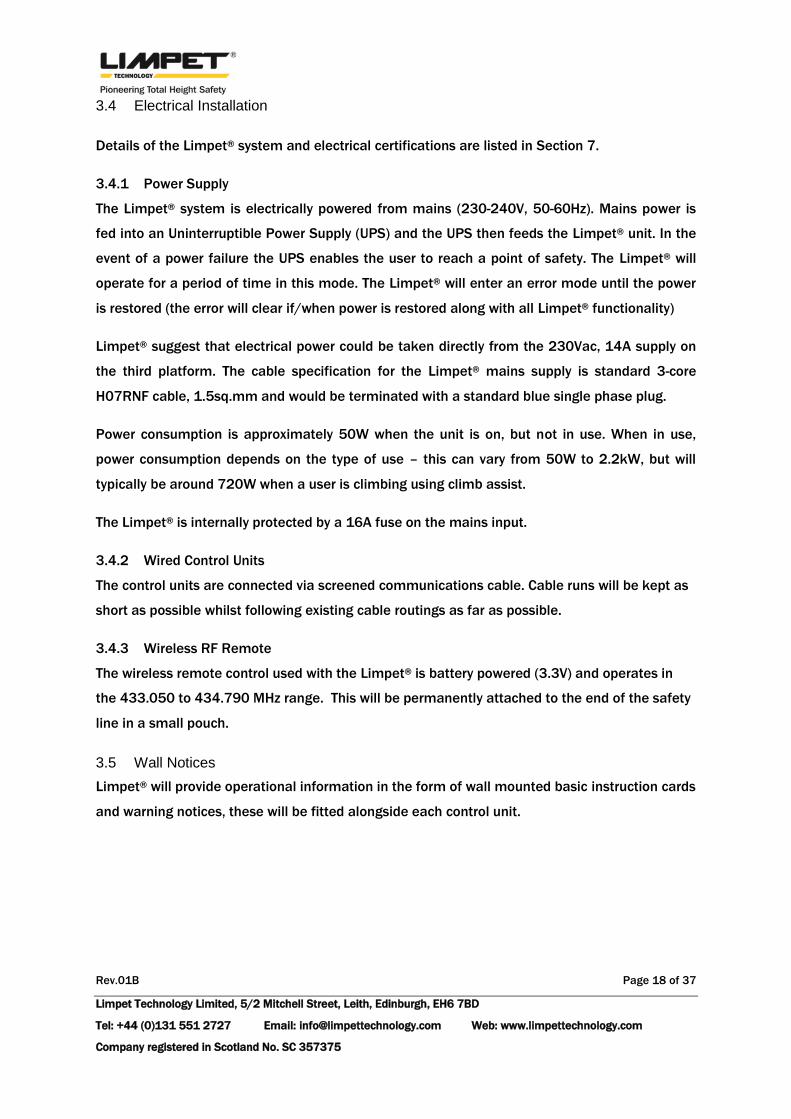
3.4 Electrical Installation
Details of the Limpet® system and electrical certifications are listed in Section 7.
3.4.1 Power Supply
The Limpet® system is electrically powered from mains (230-240V, 50-60Hz). Mains power is
fed into an Uninterruptible Power Supply (UPS) and the UPS then feeds the Limpet® unit. In the
event of a power failure the UPS enables the user to reach a point of safety. The Limpet® will
operate for a period of time in this mode. The Limpet® will enter an error mode until the power
is restored (the error will clear if/when power is restored along with all Limpet® functionality)
Limpet® suggest that electrical power could be taken directly from the 230Vac, 14A supply on
the third platform. The cable specification for the Limpet® mains supply is standard 3-core
H07RNF cable, 1.5sq.mm and would be terminated with a standard blue single phase plug.
Power consumption is approximately 50W when the unit is on, but not in use. When in use,
power consumption depends on the type of use – this can vary from 50W to 2.2kW, but will
typically be around 720W when a user is climbing using climb assist.
The Limpet® is internally protected by a 16A fuse on the mains input.
3.4.2 Wired Control Units
The control units are connected via screened communications cable. Cable runs will be kept as
short as possible whilst following existing cable routings as far as possible.
3.4.3 Wireless RF Remote
The wireless remote control used with the Limpet® is battery powered (3.3V) and operates in
the 433.050 to 434.790 MHz range. This will be permanently attached to the end of the safety
line in a small pouch.
3.5 Wall Notices
Limpet® will provide operational information in the form of wall mounted basic instruction cards
and warning notices, these will be fitted alongside each control unit.

Rev.01B Page 19 of 37
Limpet Technology Limited, 5/2 Mitchell Street, Leith, Edinburgh, EH6 7BD
Tel: +44 (0)131 551 2727 Email: [email protected] Web: www.limpettechnology.com
Company registered in Scotland No. SC 357375
4 Design of New Structural Elements
4.1 Limpet® Mounting Structure
The Limpet® unit will be bolted to the lower and upper box sections (Figure 8). Box sections will
move the Limpet® further away from the ladder rungs, making it easier to users to climb past
the unit on the climbing side of the ladder. There will be several sets of pre-drilled holes
through the box section to allow flexibility in the positioning of the Limpet®. The capacity of the
box-section used has been verified by hand-calculations (see ’Appendix A – Limpet® Mounting
Structure’) and finite element analysis has been carried out on the box-section and side plate to
verify that imposed loads will not cause excessive stress around the drilled holes.
Finite element analysis carried out for ultimate loading (20kN tension in the safety line),
showed that stresses and deflections in both the side plates and box sections remained within
acceptable limits.
Figure 8: CAD render of Limpet® ladder mounting structure
Upper box section, pre-drilled
to allow optimum positioning
of the Limpet® unit
40x40x3.2mm SHS
Ladder side plate
connected to 3No rungs
50x6mm flat bar
Lower box section, pre-drilled
to allow optimum positioning
of the Limpet® unit
40x40x3.2mm SHS

Rev.01B Page 20 of 37
Limpet Technology Limited, 5/2 Mitchell Street, Leith, Edinburgh, EH6 7BD
Tel: +44 (0)131 551 2727 Email: [email protected] Web: www.limpettechnology.com
Company registered in Scotland No. SC 357375
The worst case reaction produced at the supports of the upper box section was found to be
6.12kN (the derivation of the applied load can be found in ‘Appendix A – Limpet® Mounting
Structure’). The reactions were calculated on the assumption that the four Limpet® bolts all
carry 5kN of shear load each, under the ultimate line loading of 20kN. The reactions at the
right and left are unequal since the Limpet® is positioned eccentrically. The 6.12kN load was
applied in an upward direction to the side plates, distributed evenly over the three drilled holes.
Application of this loading produced stresses well below yield and very small deflections, see
Figure 9.
Figure 9: Von Mises stresses (left) and displacement (right) in side plate of ladder mounting bracket.
Maximum stress = 139MPa, Maximum displacement = 0.12mm

Rev.01B Page 21 of 37
Limpet Technology Limited, 5/2 Mitchell Street, Leith, Edinburgh, EH6 7BD
Tel: +44 (0)131 551 2727 Email: [email protected] Web: www.limpettechnology.com
Company registered in Scotland No. SC 357375
As described above, the loading applied to the box section was taken to be two 5kN loads
applied to one pair of drilled holes – assuming that the Limpet® bolts carry 5kN each. This
loading produced stresses that were well below yield and deflections below the serviceability
limit (which is normally taken as the total span in millimetres over 200 - in this case 2.45mm) –
see Figure 9 and Figure 10 below.
Figure 10: Von Mises stresses in horizontal member of ladder mounting bracket. Maximum stress = 117.6MPa
Figure 11: Displacement in horizontal member of ladder mounting bracket. Maximum displacement = 0.21mm

Rev.01B Page 22 of 37
Limpet Technology Limited, 5/2 Mitchell Street, Leith, Edinburgh, EH6 7BD
Tel: +44 (0)131 551 2727 Email: [email protected] Web: www.limpettechnology.com
Company registered in Scotland No. SC 357375
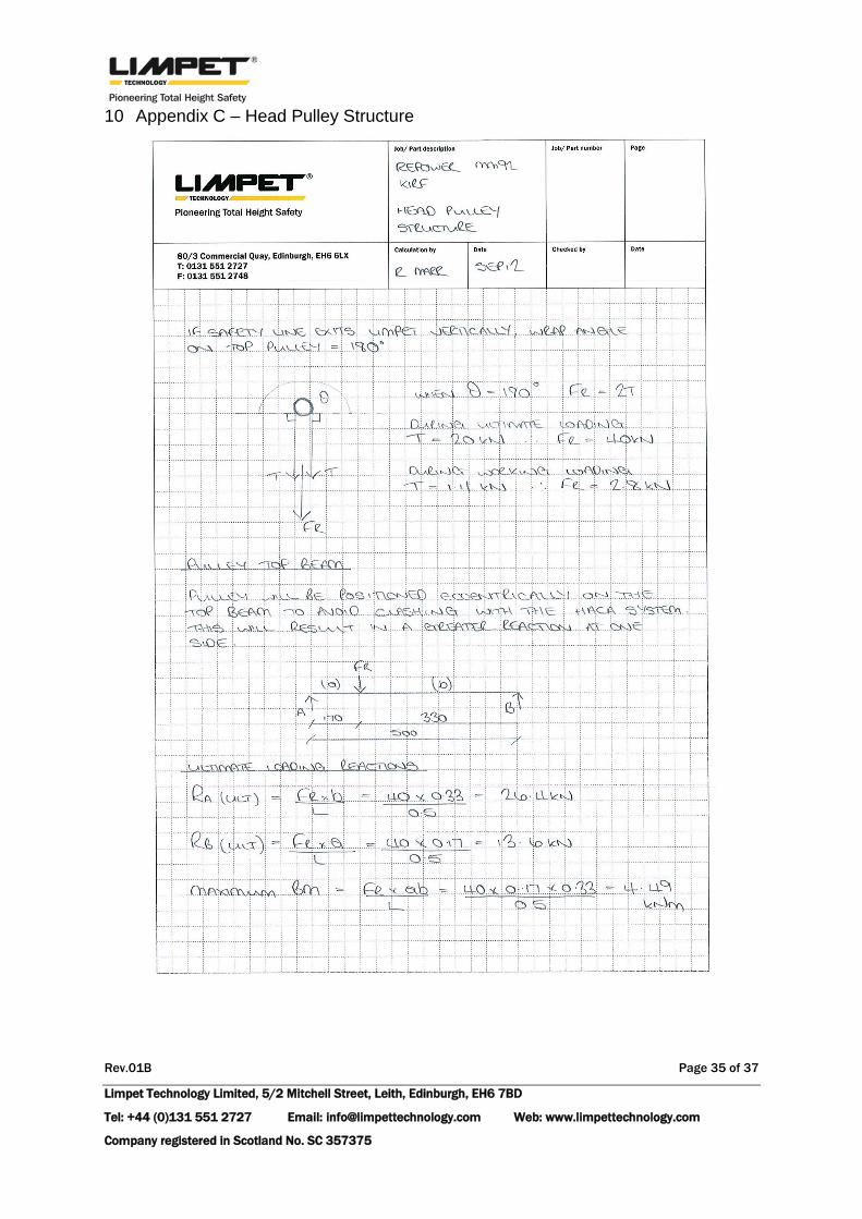
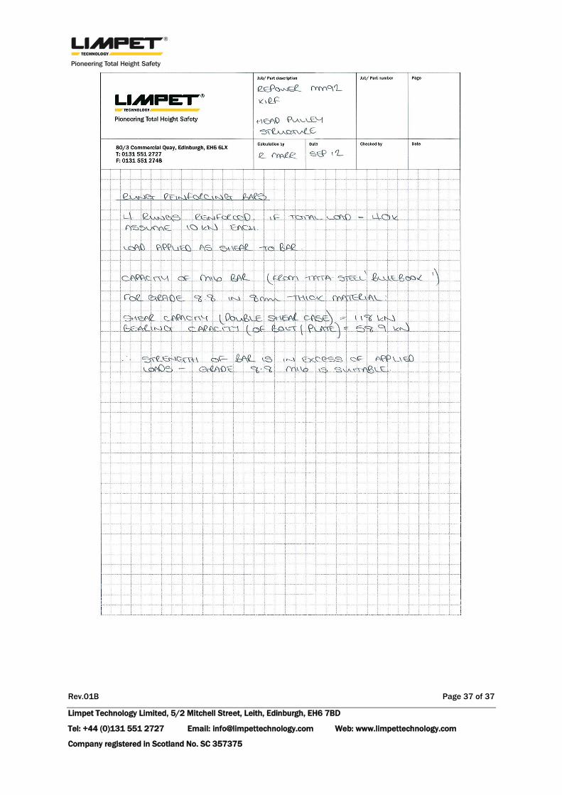
4.2 Head Pulley Structure
The head pulley structure consists of a top beam which bears onto the ladder stiles and is
welded to the ladder side-plates. The side plates will provide extra stiffness and will connect
the M16 reinforcing bars in the rungs together. As part of the installation kit and to prevent
lateral movement, Limpet® will install flat steel bar bracing to the sides of the ladder. These
will bolt into the kick-guards, avoiding the need to drill through the yaw floor, which is sealed to
prevent oil leaks.
The structure has been designed to comply with the British Standard for Structural Steel, BS
5950, for hand calculations for the box-section, flat bar and M16 bar capacity, see ‘Appendix C
– Head Pulley Structure’. Finite element analysis has also been carried out on the structure and
shows that stresses under the ultimate load case do not exceed the yield stress of the steel and
that deflections are within acceptable limits.
Figure 12: CAD Render of head pulley structure and ladder.
Pulley top beam
50x50x5mm SHS
Ladder side plate
50x8mm flat bar
Existing ladder
Lateral bracing
50x8mm flat bar
Metalwork clamped to
ladder through 4No rungs
reinforced with M16
threaded bar

Rev.01B Page 23 of 37
Limpet Technology Limited, 5/2 Mitchell Street, Leith, Edinburgh, EH6 7BD
Tel: +44 (0)131 551 2727 Email: [email protected] Web: www.limpettechnology.com
Company registered in Scotland No. SC 357375
The worst case resultant force produced by the pulley on the top beam was found to be 40kN
(the derivation of the applied load can be found in ‘Appendix C – Head Pulley Structure’). The
force was calculated on the worst-case assumption that the wrap angle of the safety line
around the pulley was ~180°and that the system is under the ultimate line loading of 20kN.
The 40kN load was applied as a remote load, dragged over the top surface of the beam.
Application of this loading produced stresses well below yield and deflections within the
serviceability limit of 2.5mm – see Figure 13 and Figure 14 below.
Figure 13: Von Mises stresses in pulley structure. Maximum stress = 250.3MPa

Rev.01B Page 24 of 37
Limpet Technology Limited, 5/2 Mitchell Street, Leith, Edinburgh, EH6 7BD
Tel: +44 (0)131 551 2727 Email: [email protected] Web: www.limpettechnology.com
Company registered in Scotland No. SC 357375
Figure 14: Displacement in pulley structure. Maximum displacement = 1.32mm

Rev.01B Page 25 of 37
Limpet Technology Limited, 5/2 Mitchell Street, Leith, Edinburgh, EH6 7BD
Tel: +44 (0)131 551 2727 Email: [email protected] Web: www.limpettechnology.com
Company registered in Scotland No. SC 357375
5 Comparison of Forces on Ladder
5.1 Summary
As an alternative to ladder-mounting the Limpet®, it would also be possible to mount the
Limpet® on the third floor platform. However, adopting this arrangement results in more severe
ladder loading, since no beneficial ‘cancelling out’ can be taken from the upwards force on the
Limpet® itself. All models are based on a 20kN ultimate line load – the maximum working load
on the system is 1.4kN.
5.2 Forces on Ladder for Ladder-Mounted Limpet®
Figure 15: Ladder mounted Limpet® and maximum and ultimate force in line
Based on geometry, the wrap angle that the safety line contacts around the top pulley is ~180°.
Therefore, the resultant force (FR) exerted down through the pulley sheave can be approximated
as:
(
)
(
)
= 40kN
20kN

Rev.01B Page 26 of 37
Limpet Technology Limited, 5/2 Mitchell Street, Leith, Edinburgh, EH6 7BD
Tel: +44 (0)131 551 2727 Email: [email protected] Web: www.limpettechnology.com
Company registered in Scotland No. SC 357375
Figure 16: Forces on head pulley and ladder for ladder mounted Limpet®
Assuming vertical equilibrium, the resultant force on the ladder will be a compressive load of
20kN (during ultimate loading). Since the ladder is a PPE clipping point, it must be rated to
20kN, therefore ladder mounting the Limpet® will keep forces within the acceptable limits.
FR
20kN 20kN
20kN

Rev.01B Page 27 of 37
Limpet Technology Limited, 5/2 Mitchell Street, Leith, Edinburgh, EH6 7BD
Tel: +44 (0)131 551 2727 Email: [email protected] Web: www.limpettechnology.com
Company registered in Scotland No. SC 357375
5.3 Forces on Ladder for Floor-Mounted Limpet®
Figure 17: Alternative Limpet® mounting solution on third floor
Safety line exits machine at ~45°
to vertical.
FV
FH
T = 20kN

Rev.01B Page 28 of 37
Limpet Technology Limited, 5/2 Mitchell Street, Leith, Edinburgh, EH6 7BD
Tel: +44 (0)131 551 2727 Email: [email protected] Web: www.limpettechnology.com
Company registered in Scotland No. SC 357375
Figure 18: Resultant force on ladder with alternative arrangement
As for the alternative arrangement, the wrap angle on the head pulley will be ~180° therefore a
total compressive load of 40kN must be resisted by the ladder and its supports. This is double
the net load on the ladder using the ladder-mounted Limpet® arrangement.
FR
20kN 20kN

Rev.01B Page 29 of 37
Limpet Technology Limited, 5/2 Mitchell Street, Leith, Edinburgh, EH6 7BD
Tel: +44 (0)131 551 2727 Email: [email protected] Web: www.limpettechnology.com
Company registered in Scotland No. SC 357375
6 Installation Method Statement and Risk Assessment
Limpet® proposes to lift all system components using the external nacelle hoist (rated to
250kg) and then lower the components through the nacelle hatch and down to the yaw
platform. The smallest dimensions of the nacelle hatch measure 700mm x 440mm, greater
than the Limpet® cross-section of 500mm x 370mm. A method statement and risk assessment
can be supplied for further details of all installation activities and operations.

Rev.01B Page 30 of 37
Limpet Technology Limited, 5/2 Mitchell Street, Leith, Edinburgh, EH6 7BD
Tel: +44 (0)131 551 2727 Email: [email protected] Web: www.limpettechnology.com
Company registered in Scotland No. SC 357375
7 Certification Details
7.1 Limpet® System
The Limpet® unit has been certified under the Machinery Directive (2006/42/EC) as well as the
PPE directive (89/686/EEC) and carries the appropriate CE markings to reflect this.
Mains power cable used in the installation is H07RNF, rated to 22A and complies with IEC
60228 class 5.
Mains connectors comply with DIN VDE 0606 T200; VDE 0110 IEC 60999: UL2238; CSA: C22.2
No 182.2-M1987
Industrial power connectors used for temporary installation comply with EN 60309-1 and EN
60309-2
Communications cable used is manufactured to UL 2919.
The Limpet® system complies with the following standards for Electromagnetic Compatibility
(EMC):
EN 61000-6-2:2005 – Electromagnetic compatibility (EMC), Emission standard for
residential, commercial and light-industrial environments.
EN 61000-6-3:2007 – EMC Emission for residential, commercial and light- industrial
environments.
EN 61000-3-2:2006 – EMC Limits for harmonic current emissions.
EN 61000-3-3:1995 + A1:2001 + A2:2006 – EMC Limitation of voltage changes,
voltage fluctuations and flicker in public low-voltage supply systems

Rev.01B Page 31 of 37
Limpet Technology Limited, 5/2 Mitchell Street, Leith, Edinburgh, EH6 7BD
Tel: +44 (0)131 551 2727 Email: [email protected] Web: www.limpettechnology.com
Company registered in Scotland No. SC 357375
7.2 Uninterruptable Power Supply
EN 60950 - Safety of information technology equipment
EN 50091-1-1 - General and safety requirements for UPS used in operator access areas
IEC 146 (CE122): Semiconductor electronic converters
The UPS has also been tested for CE marking according to European Directive 89/336 for
electromagnetic compatibility.
Standards used for showing compliance with the essential requirements for the directive:-
EN 55022:1988 Class A
EN 61000-3-2:1995 +A1: 1988 +A2: 1998
EN 61000-3-3:1995
EN 55024:1998
EN 61000-4-2:1995 +A1: 1988 Class B
EN 61000-4-3:1996 Class A
EN 61000-4-4:1995 Class B
EN 61000-4-5:1995 Class B
EN 61000-4-6:1995 Class A
EN 61000-4-8:1993 Class A
EN 61000-4-11:1994 Class C
7.3 Wireless Remote Control
The Wireless remote control EN300 220-1 v1.3.1 (2000-2009)
EN300 220-3 v1.1.1 (2000 – 2009)
RTTE Directive 1999/5/EC – Radio and Telecommunications Terminal Equipment.

Rev.01B Page 32 of 37
Limpet Technology Limited, 5/2 Mitchell Street, Leith, Edinburgh, EH6 7BD
Tel: +44 (0)131 551 2727 Email: [email protected] Web: www.limpettechnology.com
Company registered in Scotland No. SC 357375
8 Appendix A – Limpet® Mounting Structure

Rev.01B Page 33 of 37
Limpet Technology Limited, 5/2 Mitchell Street, Leith, Edinburgh, EH6 7BD
Tel: +44 (0)131 551 2727 Email: [email protected] Web: www.limpettechnology.com
Company registered in Scotland No. SC 357375

Rev.01B Page 34 of 37
Limpet Technology Limited, 5/2 Mitchell Street, Leith, Edinburgh, EH6 7BD
Tel: +44 (0)131 551 2727 Email: [email protected] Web: www.limpettechnology.com
Company registered in Scotland No. SC 357375
9 Appendix B – Limpet® Bolts
Rev.01B Page 35 of 37
Limpet Technology Limited, 5/2 Mitchell Street, Leith, Edinburgh, EH6 7BD
Tel: +44 (0)131 551 2727 Email: [email protected] Web: www.limpettechnology.com
Company registered in Scotland No. SC 357375
10 Appendix C – Head Pulley Structure

Rev.01B Page 36 of 37
Limpet Technology Limited, 5/2 Mitchell Street, Leith, Edinburgh, EH6 7BD
Tel: +44 (0)131 551 2727 Email: [email protected] Web: www.limpettechnology.com
Company registered in Scotland No. SC 357375
Rev.01B Page 37 of 37
Limpet Technology Limited, 5/2 Mitchell Street, Leith, Edinburgh, EH6 7BD
Tel: +44 (0)131 551 2727 Email: [email protected] Web: www.limpettechnology.com
Company registered in Scotland No. SC 357375