
Light Liquid Sampler - YZ Systems Light Liquid Sampler Operations Manual is a step-by-step guide...
114
LightLiquidSampler S Y S T E M S U P P O R T M A N U A L
Transcript of Light Liquid Sampler - YZ Systems Light Liquid Sampler Operations Manual is a step-by-step guide...

Light Liquid SamplerS Y S T E M S U P P O R T M A N U A L


LIGHT LIQUID SAMPLERINSTRUCTION & OPERATING
MANUALVersion: 01012007


LLLLLIGHTIGHTIGHTIGHTIGHT L L L L LIQUIDIQUIDIQUIDIQUIDIQUID S S S S SAMPLERAMPLERAMPLERAMPLERAMPLER T T T T TABLEABLEABLEABLEABLE OFOFOFOFOF C C C C CONTENTSONTENTSONTENTSONTENTSONTENTS
Page IYZ - Milton Roy • 201 Ivyland Road • Ivyland, Pa. • USA • 18974 • P: 281.362.6500 • F: 281.362.6513Light Liquid Sampler ver.01012007
Table of Contents .............................................................................................................................. I
Section 1: First Things To Know ....................................................................................................1How to Use this Manual .......................................................................................................................1Typographic Conventions ....................................................................................................................1Getting Help .........................................................................................................................................1Operation Specifications .....................................................................................................................2Theory of Operation ............................................................................................................................3System Accessories ...........................................................................................................................3
Section 2: System Installation.........................................................................................................5Standard System Components
Probe Mounted Pumps (PNR).......................................................................................................5Skid Mounted Pumps (LPR) ..........................................................................................................8
System Flow SchematicPneumatic Actuated
Probe Mounted (PNR-2P) ........................................................................................................12Skid Mounted (LPR-2P) ............................................................................................................13
Hydraulic ActuatedProbe Mounted (PNR-2H) ........................................................................................................14Skid Mounted (LPR-2H) ............................................................................................................15
Standard System MountingSkids ...........................................................................................................................................16Cabinets ......................................................................................................................................17
Standard System ConnectionsPneumatic Actuated Skids
Probe Mounted (PNR-2S-xP) ...................................................................................................18Skid Mounted (LPR-2S-xP) ......................................................................................................19
Pneumatic Actuated CabinetsProbe Mounted (PNR-2C-xP) ...................................................................................................20Skid Mounted (LPR-2C-xP) ......................................................................................................22
Hydraulic Actuated SkidsProbe Mounted (PNR-2S-xH) ...................................................................................................23Skid Mounted (LPR-2S-xH) ......................................................................................................25
Hydraulic Actuated CabinetsProbe Mounted (PNR-2C-xH) ...................................................................................................27Skid Mounted (LPR-2C-xH) ......................................................................................................29
Pump Sample Size ...........................................................................................................................31
Section 3: Filling the Pre-Charge Vessel ....................................................................................33Filling the Vessel ................................................................................................................................33

LLLLLIGHTIGHTIGHTIGHTIGHT L L L L LIQUIDIQUIDIQUIDIQUIDIQUID S S S S SAMPLERAMPLERAMPLERAMPLERAMPLER T T T T TABLEABLEABLEABLEABLE OFOFOFOFOF C C C C CONTENTSONTENTSONTENTSONTENTSONTENTS
YZ - Milton Roy • 201 Ivyland Road • Ivyland, Pa. • USA • 18974 • P: 281.362.6500 • F: 281.362.6513Page II Light Liquid Sampler ver.01012007
Table of Contents ............................................................................................................................. II
Section 4: System Control & Electronics ....................................................................................35Overview ...........................................................................................................................................35Pneumatic Actuated Control Options
“-0” Control By Customer ............................................................................................................36“-1A” 24 VDC Time Delay Relay ..................................................................................................37“-1B” 120 VAC Time Delay Relay ................................................................................................38“4A” 24 VDC / 4-20mA.................................................................................................................39“4B” 120 VAC / 4-20mA ...............................................................................................................40“6A” 12-24 VDC Timer/Counter (Z-65).........................................................................................41“6B” 120 VAC Timer/Counter (Z-65) ............................................................................................42“6M” 12-24 VDC Timer/Counter (Z-65 w/PIM Card) .....................................................................437B” 120 VAC 4 Digit Counter (ATC) .............................................................................................44
Hydraulic Sctuated Control Options“1B” 120 VAC Time Delay Relay ..................................................................................................45“4B” 120 VAC / 4-20mA ...............................................................................................................46“7B” 120 VAC 4 Digit Counter (ATC) ...........................................................................................47
Section 5: Programming for Proportional-to-Flow Operation ...................................................49Setting Operator Input Parameters ...................................................................................................49
“-0” Control By Customer ............................................................................................................50“-1” Control Option.......................................................................................................................51“4” Control Option ........................................................................................................................53“6” Control Option ........................................................................................................................58“7” Control Option ........................................................................................................................61
Section 6: Mechanical System ......................................................................................................63Sample Pumps and Balance Valves
PNR-2P .......................................................................................................................................63LPR-2P .......................................................................................................................................64PNR-2H .......................................................................................................................................65LPR-2H .......................................................................................................................................66
Accumulator Vessel ..........................................................................................................................675-Way Cross .....................................................................................................................................68Actuation/Mixing System (Pneu)........................................................................................................69Actuation/Mixing System (Hyd.) .........................................................................................................70
Section 7: System Operation ........................................................................................................71Preparing The System for Operation ................................................................................................71Sample Pump Priming ......................................................................................................................71Product Line Test ..............................................................................................................................71Portable Sample Vessel Connection .................................................................................................71

LLLLLIGHTIGHTIGHTIGHTIGHT L L L L LIQUIDIQUIDIQUIDIQUIDIQUID S S S S SAMPLERAMPLERAMPLERAMPLERAMPLER T T T T TABLEABLEABLEABLEABLE OFOFOFOFOF C C C C CONTENTSONTENTSONTENTSONTENTSONTENTS
Page IIIYZ - Milton Roy • 201 Ivyland Road • Ivyland, Pa. • USA • 18974 • P: 281.362.6500 • F: 281.362.6513Light Liquid Sampler ver.01012007
Table of Contents ............................................................................................................................ III
Section 8: System Maintenance ...................................................................................................75Preventative Maintenance Schedule .................................................................................................75
Recommended Maintenance Schedule ......................................................................................75Monthly Inspection ....................................................................................................................75Annual Inspection .....................................................................................................................75Bi-Annual Inspection .................................................................................................................75
Recommended Spare Parts List .................................................................................................75
Section 9: System Troubleshooting .............................................................................................. 77Pneumatic Systems:
How to Use This Section .............................................................................................................77For Additional Help .......................................................................................................................77Step-by-Step Resolution ..............................................................................................................77
Actuation Gas Pressure ....................................................................................................................77Actuation Gas Pressure Troubleshooting Steps ..........................................................................77
Electrical Power ................................................................................................................................78Electrical Power Troubleshooting Steps ......................................................................................78
Sample Pulse ....................................................................................................................................79Sample Pulse Troubleshooting Steps .........................................................................................79
Pump Performance ...........................................................................................................................79Pump Performance Troubleshooting Steps ................................................................................79
Pre-Charge/Product Accumulator .....................................................................................................80Pre-Charge/Product Accumulator Troubleshooting Steps ...........................................................80
Hydraulic Systems:How to Use This Section .............................................................................................................81For Additional Help .......................................................................................................................81Step-by-Step Resolution ..............................................................................................................81
Electrical Power ................................................................................................................................81Electrical Power Troubleshooting Steps ......................................................................................82Sample Pulse Troubleshooting Steps .........................................................................................82
Hydraulic Power ................................................................................................................................83Hydraulic Power Troubleshooting Steps ......................................................................................83

LLLLLIGHTIGHTIGHTIGHTIGHT L L L L LIQUIDIQUIDIQUIDIQUIDIQUID S S S S SAMPLERAMPLERAMPLERAMPLERAMPLER T T T T TABLEABLEABLEABLEABLE OFOFOFOFOF C C C C CONTENTSONTENTSONTENTSONTENTSONTENTS
YZ - Milton Roy • 201 Ivyland Road • Ivyland, Pa. • USA • 18974 • P: 281.362.6500 • F: 281.362.6513Page IV Light Liquid Sampler ver.01012007
Table of Contents ........................................................................................................................... IV
Appendix A: Illustrations ................................................................................................................87PNR-2P Sample Pump Assembled ..................................................................................................87LPR-2P Sample Pump Assembled ...................................................................................................88PNR-2H Sample Pump Assembled ..................................................................................................89LPR-2H Sample Pump Assembled ................................................................................................... 90Balance Valve Assembly, Exploded View ..........................................................................................915-Way Cross Assembly.....................................................................................................................92Pre-Charge System ..........................................................................................................................93Pneumatic Product Accumulator VesselProduct Accumulator Vessel .............................................................................................................94Mixing System-Accumulator ..............................................................................................................95Mixing System ...................................................................................................................................96Hydraulic Product Accumulator VesselProduct Accumulator Vessel .............................................................................................................97Mixing System-Accumulator ..............................................................................................................98Mixing System ...................................................................................................................................99Hydraulic Power Pack .....................................................................................................................100Hydraulic Power Pack/Test Switch ..................................................................................................101Electrical Wiring Hydraulic Power Pack/Test Switch.......................................................................102Z-65 Wiring Control Document .......................................................................................................103Z-200 Wiring Control Document...................................................................................................... 104

SSSSSECTIONECTIONECTIONECTIONECTION 1: 1: 1: 1: 1:FFFFFIRSTIRSTIRSTIRSTIRST T T T T THINGSHINGSHINGSHINGSHINGS T T T T TOOOOO K K K K KNOWNOWNOWNOWNOW A A A A ABOUTBOUTBOUTBOUTBOUT L L L L LIGHTIGHTIGHTIGHTIGHT L L L L LIQUIDIQUIDIQUIDIQUIDIQUID S S S S SAMPLERSAMPLERSAMPLERSAMPLERSAMPLERS
Page 1YZ - Milton Roy • 201 Ivyland Road • Ivyland, Pa. • USA • 18974 • P: 281.362.6500 • F: 281.362.6513Light Liquid Sampler ver.01012007
How to Use this Manual
The Light Liquid Sampler Operations Manual is astep-by-step guide containing the proceduresneeded to work with the Light Liquid SamplerSystem.
The Light Liquid Sampler Series of samplers imple-ment the most advanced technology available in theindustry. It is recommended that the techniciansworking with the Light Liquid Sampler Systemsstudy the manual prior to initiating work on thesystem for the first time.
Typographic Conventions
To aide in readability, this manual uses severaltypographic conventions. References to illustrations,photographs, and other related content will appear initalicized text along with the location of where to find theitem in the manual. Digital versions of the manual,available in Adobe Acrobat™ PDF format, will behighlighted further in blue italic text indicating the copyretains a hyperlink to the referenced item.
Measurement units are listed in italic parenthesis textfollowing their US standard equivalent. As an example,for defining a distance, 15' (4.5 meters), is how the textwill appear throughout the manual.
Items that require action, for example the pressing of a keyfor programming the controller, will feature the action item insentence case Bold Text followed in normal text by theitem such as, the Up Arrow key or Main Power switch.
™ Adobe Acrobat & Acrobat Reader are trademarks of Adobe Systems, Inc.
Getting Help
This manual provides solutions to typical questionsabout the Light Liquid Sampler system. If theanswer can not be found within this manual, contactYZ Systems at:
T: 1.281.362.6500T: 1.800.653.9435F: 1.281.362.6513Em: [email protected]
When calling, have this manual close at hand.Whether calling or writing, please include in yourcommunique the following information:
• The serial number of the Light Liquid SamplerSystem and the version number of this manual.The serial number is located on the system skid orenclosure. The version number of this manual islocated at the bottom of each page.
• A description of the problem and, if applicable theactions of the technical personnel when the problemoccurred.

SSSSSECTIONECTIONECTIONECTIONECTION 1: 1: 1: 1: 1:FFFFFIRSTIRSTIRSTIRSTIRST T T T T THINGSHINGSHINGSHINGSHINGS T T T T TOOOOO K K K K KNOWNOWNOWNOWNOW A A A A ABOUTBOUTBOUTBOUTBOUT L L L L LIGHTIGHTIGHTIGHTIGHT L L L L LIQUIDIQUIDIQUIDIQUIDIQUID S S S S SAMPLERSAMPLERSAMPLERSAMPLERSAMPLERS
YZ - Milton Roy • 201 Ivyland Road • Ivyland, Pa. • USA • 18974 • P: 281.362.6500 • F: 281.362.6513Page 2 Light Liquid Sampler ver.01012007
Operation Specifications
Maximum Output:Std. 3/8” Plunger 6.8 gallons/day
(25.3 liters/day)Opt.1/2” Plunger 12.17 gallons/day
(46.07 liters/day)Opt.5/8” Plunger 19.02 gallons/day
(72.0 liters/day)Opt.1” Plunger 24.34 gallons/day
(92.07 liters/day)
Maximum Operating Pressure: 1,800 psig(124 Bar (g)
Pump Displacement:Std. 3/8” Plunger .25 - 1.8 cc/StrokeOpt.1/2” Plunger 0.8 - 3.2 cc/StrokeOpt.5/8” Plunger 1.25 - 5.0cc/StrokeOpt.1” Plunger 1.6 - 12.8cc/Stroke
Operating Temp Range: 0 to 140 degrees F.(-17°C to 60°C)
Power Supply Options:Pneumatic 120 VAC @ 1 AMP
VDCHydraulic 120 VAC @ 20 AMP
Flow Signal: *Customer Supplied
Actuation Gas; 100 psi InstrumentQuality Gas
Note: at temperatures below 32º F (0º C), condition-ing of the actuation gas supply may be required.Where the actuation gas supply has a high watercontent and/or a low hydrocarbon dew point, addi-tional actuation gas filtration or heating of the actua-tion gas supply may be necessary. Bottled nitrogencan also be used during cold operating conditions toavoid condensation in the actuation gas supply line.In addition, operation at extreme temperatures mayaffect system performance. To enhance the perfor-mance of this system, adequate heat should beprovided to maintain an operating environmentabove 30° F (-1º C).
* Refer to Manual Section 4, System Control Options

SSSSSECTIONECTIONECTIONECTIONECTION 1: 1: 1: 1: 1:FFFFFIRSTIRSTIRSTIRSTIRST T T T T THINGSHINGSHINGSHINGSHINGS T T T T TOOOOO K K K K KNOWNOWNOWNOWNOW A A A A ABOUTBOUTBOUTBOUTBOUT L L L L LIGHTIGHTIGHTIGHTIGHT L L L L LIQUIDIQUIDIQUIDIQUIDIQUID S S S S SAMPLERSAMPLERSAMPLERSAMPLERSAMPLERS
Page 3YZ - Milton Roy • 201 Ivyland Road • Ivyland, Pa. • USA • 18974 • P: 281.362.6500 • F: 281.362.6513Light Liquid Sampler ver.01012007
Theory of Operation
The Light Liquid sampling systems are designedto sample light liquid hydrocarbons. Thousandsof individual samples are captured and combinedto develop a representative, composite sample ofthe flowing pipeline.
Operation of the sampling system centersaround the following primary components: theSample Pump, the Product Accumulator Vessel,the Precharge Gas Vessel, and the ElectronicControl System. All equipment, except probemounted Sample Pumps are mounted on asteel skid, or in a system enclosure. Thesecomponents are shown in the diagrams on thefollowing pages.
The sampling system operates on a simpleconcept. When the system receives a properflow signal (by others), the electronic control unitenergizes either a solenoid valve, or a HydraulicPower Pack. Energizing the solenoid valve, orHydraulic Power Pack allows a pressurizedpulse into the actuation cylinder of the samplepump, which in turn causes the pump to stroke.When the pump strokes, a small sample isdisplaced into the product accumulator vessel.Once the solenoid valve, or Hydraulic PowerPack is de-energized, the sample pump plungerreturns to its normal position. This action allowsa new sample bite to be captured in the pump.
The purpose of the YZ light liquid hydrocarbonsampling system is to capture and maintain arepresentative liquid sample of the pipelineproduct. The sampled product is maintained in aliquid phase by the product accumulator vessel’sfree floating piston and the precharge gas sys-tem. In order for the system to function properly,pipeline product must be single phase, liquidproduct.
By properly adjusting both the sample size andthe sample frequency, the sample vessel will fillto 80% capacity at the end of the sample period.Once the sample period is complete, the productwithin the sample receiver is thoroughly mixedusing the power mixer. A representative samplecan then be removed from the product accumu-lator vessel using the YZ DuraSite, a DOTapproved constant pressure sample vessel, referto page 72-73.
After removing the remainder of the product fromthe accumulator vessel, the system is then readyfor a new sample period.
System Accessories• DuraSite, portable DOT approved constant pres-
sure sample vessels. Available in 150, 300, 500,800, and 1000 cc sizes.
• KK-1, KK-2, & KK-3: carrying cases for DuraSitesthat meet DOT requirements for transportingportable sample vessels.
• 1/4" stainless steel tubing Dielectric Isolator Union.These should be installed in every tubing line thatattaches the sampler to the pipeline in anymanner. For example the supply gas, productconnection to the system, and differential pres-sure switch connections, (P/N A1-0182).
A complete line of sampling accessories rangingfrom sample probes to sample vessels is availablethrough YZ - Milton Roy. Please contact your localrepresentative or YZ - Milton Roy toll free at800.344.5399. For technical support call800.653.9435.

SSSSSECTIONECTIONECTIONECTIONECTION 1: 1: 1: 1: 1:FFFFFIRSTIRSTIRSTIRSTIRST T T T T THINGSHINGSHINGSHINGSHINGS T T T T TOOOOO K K K K KNOWNOWNOWNOWNOW A A A A ABOUTBOUTBOUTBOUTBOUT L L L L LIGHTIGHTIGHTIGHTIGHT L L L L LIQUIDIQUIDIQUIDIQUIDIQUID S S S S SAMPLERSAMPLERSAMPLERSAMPLERSAMPLERS
YZ - Milton Roy • 201 Ivyland Road • Ivyland, Pa. • USA • 18974 • P: 281.362.6500 • F: 281.362.6513Page 4 Light Liquid Sampler ver.01012007
Notes

SSSSSECTIONECTIONECTIONECTIONECTION 2: 2: 2: 2: 2: S S S S SYYYYYSTEMSTEMSTEMSTEMSTEM I I I I INSTNSTNSTNSTNSTALLAALLAALLAALLAALLATIONTIONTIONTIONTION
Page 5YZ - Milton Roy • 201 Ivyland Road • Ivyland, Pa. • USA • 18974 • P: 281.362.6500 • F: 281.362.6513Light Liquid Sampler ver.01012007
Standard Probe Mounted Pump(PNR) System ComponentsStandard primary components of the ProbeMounted Pump System (PNR-2) include thefollowing:• Sample Pump/Balance Valve, figure 1.
Pneumatically or Hydraulically actuated PNR-2probe mounted Sample Pump.
• System Skid, figure 2 (Pneumatic), figure 3 (Hy-draulic), & figure 4 (Both). Houses theAccumulator Vessel, Pre-charge Vessel, andSystem Electronics Enclosure.
• Product Accumulator Vessel, figure 2 (PneumaticSkid), figure 3 (Hydraulic Skid), figure 4 (Both), &figures 5 & 6 (Cabinet Type). 1.5 gallon (5.68 Liters),3 Gallon (11.36 Liters), 5 Gallon (18.93 Liters).
• Pre-Charge Vessel, figure 2 (Pneumatic Skid),figure 3 (Hydraulic Skid), figure 4 (Both), &figures 5 & 6 (Cabinet Type). Sized to matchProduct Accumulator volume.
figure 1
figure 3
IS O LA T IO N V ALV E
F LO W
SU P P LY P R O B E
(FR O M SK ID )P N E U M A TIC S U P PLY
(TO S K ID )P R O D U C T O U T
Actuation Supply(From Skid or Cabinet)
(To Skid or Cabinet)
24VDC SIGNAL IN(BY CUSTOMER)3/4" FNPT PROVIDED
PNEUMATIC SUPPLY(TO PUMP) 1/4" TUBINGCONNECTION PROVIDED
3 WAY SOLENOID VALVE
FILTER/REGULATOR
PNEUMATICSUPPLY IN(BY CUSTOMER)1/4" FNPTPROVIDED
MIXING VALVE
86" 56"
40" 1
120VAC IN(BY CUSTOMER)3/4" FNPTPROVIDED
LIFTINGHOOK
PNEUMATICPOWER MIXER
figure 2
Flow SIGNALPOWER IN
40" (1.5 Gal.) 56" (3 Gal.) 86" (5 Gal.)
23 3/4"
Pack
120 VAC
m Pump
movallve
duct
duct
sselcumulator
Hydraulic
Switch
Power
Test/Mixing
ModeSwitch
gnetic Level Monitor
lume Scale
lumeicator
's)
ElectronicTo Customer4-20mA
37 1/4" (1.5 Gal.) 53 1/4" (3 Gal.) 83 1/4" (5 Gal.)
HydraulicPneumatic

SSSSSECTIONECTIONECTIONECTIONECTION 2: 2: 2: 2: 2: S S S S SYYYYYSTEMSTEMSTEMSTEMSTEM I I I I INSTNSTNSTNSTNSTALLAALLAALLAALLAALLATIONTIONTIONTIONTION
YZ - Milton Roy • 201 Ivyland Road • Ivyland, Pa. • USA • 18974 • P: 281.362.6500 • F: 281.362.6513Page 6 Light Liquid Sampler ver.01012007
1000
1500500
2000p si
PRECHARGESUPPLY IN(BY CUSTOMER)1/4" FNPTPROVIDED
MAGNETICVOLUMEINDICATOR
VOLUMESCALE (cc's)
PRODUCTREMOVALVALVE
RELIEFVALVE
PRODUCTACCUMULATORCYLINDER
PRECHARGEVESSEL
PRODUCT IN (FROM PUMP)1/4" TUBING CONNECTIONPROVIDED
500
2000psi
1500
1000
• Five-Way Cross, figure 4 (Skid) & figures 5 & 6(Cabinets) mounts the Pressure Gage, Relief Valve,Product Isolation, and Product Removal Valves.
figure 4
Standard Probe Mounted Pump(PNR) System Components

SSSSSECTIONECTIONECTIONECTIONECTION 2: 2: 2: 2: 2: S S S S SYYYYYSTEMSTEMSTEMSTEMSTEM I I I I INSTNSTNSTNSTNSTALLAALLAALLAALLAALLATIONTIONTIONTIONTION
Page 7YZ - Milton Roy • 201 Ivyland Road • Ivyland, Pa. • USA • 18974 • P: 281.362.6500 • F: 281.362.6513Light Liquid Sampler ver.01012007
• System Cabinet, figure 5 (Pneumatic) & figure 6(Hydraulic). Houses the Accumulator Vessel, Pre-charge Vessel, Five-Way Cross, and System Elec-tronics Enclosure.
figure 5
PRODUCTACCUMULATORVESSEL
5-WAY CROSS
MIXING VALVE
PRESSUREREGULATOR
SOLENOID VALVE
SYSTEM CONTROL
ENCLOSURE(XP BOX)
FRONT
1500
1000
500
2000psi
500
2000psi
1500
1000
PRE-CHARGEVESSEL
J
O
N
L
M
K
I
H
G
E
FRONT VIEWENCLOSURE DOOR SHOWN REMOVED FOR DRAWING CLARITY.
2000
15001000
500
psi
15005001000
2000psi
40"
K
M
G
H
Standard Probe Mounted Pump(PNR) System Components
figure 6Pneumatic Hydraulic

SSSSSECTIONECTIONECTIONECTIONECTION 2: 2: 2: 2: 2: S S S S SYYYYYSTEMSTEMSTEMSTEMSTEM I I I I INSTNSTNSTNSTNSTALLAALLAALLAALLAALLATIONTIONTIONTIONTION
YZ - Milton Roy • 201 Ivyland Road • Ivyland, Pa. • USA • 18974 • P: 281.362.6500 • F: 281.362.6513Page 8 Light Liquid Sampler ver.01012007
Standard Skid Mounted Pump(LPR) System ComponentsStandard primary components of the Skid MountedPump System (LPR-2) include the following:
• System Skid/Cabinet, figure 7, figure 8, figure 9,figure 10, figure 11, and figure 12. Houses theSample Pump, Accumulator Vessel, Pre-chargeVessel, Five-Way Cross, and System Electronics.
• Sample Pump/Balance Valve, figure 7, figure 9,figure 11, and figure 12. The LPR-2 slip streamSample Pump is mounted either; on the front ofthe sampler skid, or inside the cabinet.
• Product Accumulator Vessel, figure 7, figure 8,figure 9, figure 10, figure 11, and figure 12,1.5 gallon (5.68 Liters), 3 Gallon (11.36 Liters),5 Gallon (18.93 Liters).
• Pre-Charge Vessel, figure 7, figure 8, figure 9,figure 10, figure 11, and figure 12. Sized to matchProduct Accumulator volume.
• Five-Way Cross, figure 7, figure 9, figure 11, andfigure 12. mounts the Pressure Gage, ReliefValve, Product Isolation, and Product RemovalValves.
• Pneumatic System, figure 8, and figure 11.Provides power for the Sample Pump actuation,and the Mixing system for the Product Accumula-tor Vessel.
figure 7
Pneumatic PowerMixer
Product AccumulatorVessel
Product RemovalValve
Precharge Supply
Product Loop Return
LPR-2 Pump0-1.8 cc/stroke
psi2000
1500
1000
500
Volume Scale(cc's)
Magnetic VolumeIndicator
Balance Valve
Precharge Vessel
Product Loop Supply
Relief Valve
500 15001000
psi2000
24"
86" 5 Gallon56" 3 Gallon
40" 1.5 Gallon
Signal
sel
ply
lator
30”
30”
24VDC SIGNAL IN(BY CUSTOMER)3/4" FNPT PROVIDED
PNEUMATIC SUPPLY(TO PUMP) 1/4" TUBINGCONNECTION PROVIDED
3 WAY SOLENOID VALVE
FILTER/REGULATOR
PNEUMATICSUPPLY IN(BY CUSTOMER)1/4" FNPTPROVIDED
MIXING VALVE
86" 5 G56" 3 G
40" 1.5 G
120VAC IN(BY CUSTOMER)3/4" FNPTPROVIDED
LIFTINGHOOK
PNEUMATICPOWER MIXER
figure 8
Supply Power

SSSSSECTIONECTIONECTIONECTIONECTION 2: 2: 2: 2: 2: S S S S SYYYYYSTEMSTEMSTEMSTEMSTEM I I I I INSTNSTNSTNSTNSTALLAALLAALLAALLAALLATIONTIONTIONTIONTION
Page 9YZ - Milton Roy • 201 Ivyland Road • Ivyland, Pa. • USA • 18974 • P: 281.362.6500 • F: 281.362.6513Light Liquid Sampler ver.01012007
• Hydraulic PowerPak, figure 10 & figure 12. Pro-vides hydraulic power for the Sample Pumpactuation, and the Mixing system for the ProductAccumulator Vessel.
24"
ReliefValve
Product LoopReturn
Product LoopSupply
PrechargeVessel
ProductRemovalValve
1000500
psi
1500
2000
5 GallonProductAccumulatorVessel
BalanceValve
1500
2000
PrechargeSupply
psi
5001000
LiftingHook
LPR-2Pump
MagneticVolumeIndicator
figure 9
ProductAccumulatorVessel
Five-Way Cross
86" 56"
40" 1
BACK VIEW
XP ENCLOSURE
TEST/MIXINGSWITCH
MODE SWITCH
120VAC IN(BY CUSTOMER)1/2" FNPTPROVIDED
HYDRAULIC POWER MIXER
DRY CONTACTCLOSURE IN(BY CUSTOMER)1/2" FNPTPROVIDED
DIVERTERVALVE
HYDRAULICPOWER PACK
LIFTINGHOOK
figure10
30”
Supply Power
FlowSignal
Standard Skid Mounted Pump(LPR) System Components
SSSSSECTIONECTIONECTIONECTIONECTION 2: 2: 2: 2: 2: S S S S SYYYYYSTEMSTEMSTEMSTEMSTEM I I I I INSTNSTNSTNSTNSTALLAALLAALLAALLAALLATIONTIONTIONTIONTION
YZ - Milton Roy • 201 Ivyland Road • Ivyland, Pa. • USA • 18974 • P: 281.362.6500 • F: 281.362.6513Page 10 Light Liquid Sampler ver.01012007
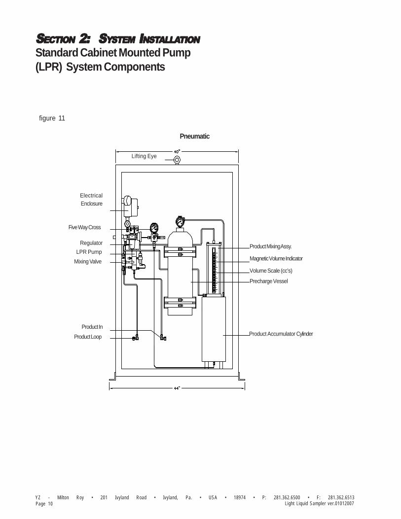
Standard Cabinet Mounted Pump(LPR) System Components
figure 11
Magnetic Volume Indicator
Lifting Eye
Electrical Enclosure
Five Way Cross
Regulator
LPR Pump
Mixing Valve
Product In
Product Loop
Volume Scale (cc’s)
Precharge Vessel
Product Accumulator Cylinder
Product Mixing Assy.
Pneumatic

SSSSSECTIONECTIONECTIONECTIONECTION 2: 2: 2: 2: 2: S S S S SYYYYYSTEMSTEMSTEMSTEMSTEM I I I I INSTNSTNSTNSTNSTALLAALLAALLAALLAALLATIONTIONTIONTIONTION
Page 11YZ - Milton Roy • 201 Ivyland Road • Ivyland, Pa. • USA • 18974 • P: 281.362.6500 • F: 281.362.6513Light Liquid Sampler ver.01012007
Standard Cabinet Mounted Pump(LPR) System Components
figure 12
44"
40"
Lifting Eye
1000
500
psi
1500
2000
SAMPLE VESSEL
PRECHARGE VESSEL
HYDRAULICMIXING ASSEMBLY
10001500
psi2000
500
HYDRAULICPOWER PACK
DIVERTER VALVE
TEST/MIXMODE SWITCH
TDR
LPR-2HPUMP
Hydraulic
SSSSSECTIONECTIONECTIONECTIONECTION 2: 2: 2: 2: 2: S S S S SYYYYYSTEMSTEMSTEMSTEMSTEM I I I I INSTNSTNSTNSTNSTALLAALLAALLAALLAALLATIONTIONTIONTIONTION
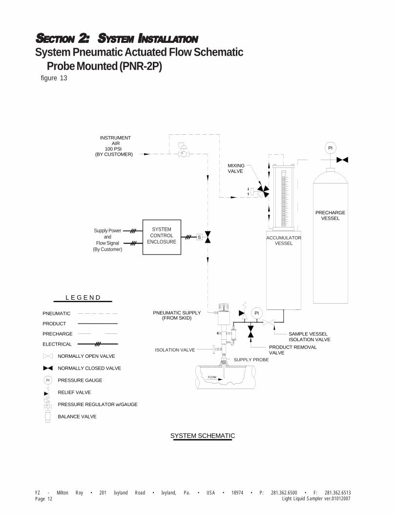
YZ - Milton Roy • 201 Ivyland Road • Ivyland, Pa. • USA • 18974 • P: 281.362.6500 • F: 281.362.6513Page 12 Light Liquid Sampler ver.01012007
System Pneumatic Actuated Flow SchematicProbe Mounted (PNR-2P)
figure 13
VESSEL
ELECTRICAL
PRECHARGE
PRESSURE REGULATOR w/GAUGE
BALANCE VALVE
RELIEF VALVE
NORMALLY CLOSED VALVE
PRESSURE GAUGE
NORMALLY OPEN VALVE
PNEUMATIC
PRODUCT
L E G E N D
METERED CONTACTS
120 VAC
SUPPLY PROBE
SYSTEM SCHEMATIC
ISOLATION VALVE
FLOW
PRODUCT REMOVALVALVE
ISOLATION VALVESAMPLE VESSEL
PNEUMATIC SUPPLY(FROM SKID)
w/ATCCOUNTER
ENCLOSURECONTROLSYSTEM
S
VESSEL
5 GALLONSAMPLE
(BY CUSTOMER)
INSTRUMENT
100 PSIAIR
PRECHARGE
PI
VALVEMIXING
ACCUMULATORVESSEL
ISOLATION VALVE
SUPPLY PROBE
SYSTEMCONTROL
ENCLOSURE
Supply Powerand
Flow Signal(By Customer)

SSSSSECTIONECTIONECTIONECTIONECTION 2: 2: 2: 2: 2: S S S S SYYYYYSTEMSTEMSTEMSTEMSTEM I I I I INSTNSTNSTNSTNSTALLAALLAALLAALLAALLATIONTIONTIONTIONTION
Page 13YZ - Milton Roy • 201 Ivyland Road • Ivyland, Pa. • USA • 18974 • P: 281.362.6500 • F: 281.362.6513Light Liquid Sampler ver.01012007
System Pneumatic Actuated Flow SchematicSkid Mounted (LPR-2P)
figure 14
L E G E N D
RETURNPRODUCT
PUMPSAMPLINGLPR-2
BALANCE VALVE
PRODUCT
PRECHARGE
ELECTRICAL
PNEUMATIC
NORMALLY OPEN VALVE
NORMALLY CLOSED VALVE
PRESSURE GAUGE
RELIEF VALVE
PRESSURE REGULATOR w/GAUGE
PRODUCT REMOVALPRODUCTINLET VALVE
ISOLATION VALVESAMPLE VESSEL
METERED CONTACTS w/ATCCOUNTER
120 VACENCLOSURE
CONTROLSYSTEM
(BY CUSTOMER)100 PSI
AIRINSTRUMENT
VESSELSAMPLE
S
VESSELPRECHARGE
VALVEMIXING
PI
SYSTEM SCHEMATIC
3 GALLON
Supply Powerand
Flow Signal(By Customer)

SSSSSECTIONECTIONECTIONECTIONECTION 2: 2: 2: 2: 2: S S S S SYYYYYSTEMSTEMSTEMSTEMSTEM I I I I INSTNSTNSTNSTNSTALLAALLAALLAALLAALLATIONTIONTIONTIONTION
YZ - Milton Roy • 201 Ivyland Road • Ivyland, Pa. • USA • 18974 • P: 281.362.6500 • F: 281.362.6513Page 14 Light Liquid Sampler ver.01012007
System Hydraulic Actuated Flow SchematicProbe Mounted (PNR-2H)
figure 15
PNR-2
PUMPSAMPLING
ENCLOSURE
SYSTEMCONTROL
SAMPLEVESSEL
ISOLATION VALVESAMPLE VESSEL
PRODUCT REMOVALVALVE
PRECHARGEVESSEL
PIPELINE
FLOW
L E G E N D
PRECHARGE
PRODUCT
ELECTRICAL
NORMALLY OPEN VALVE
HYDRAULIC
RELIEF VALVE
THREE WAY VALVE
PRESSURE GAUGE
NORMALLY CLOSED VALVE
HydraulicPower Pack
Supply Powerand
Flow Signal(By Customer)

SSSSSECTIONECTIONECTIONECTIONECTION 2: 2: 2: 2: 2: S S S S SYYYYYSTEMSTEMSTEMSTEMSTEM I I I I INSTNSTNSTNSTNSTALLAALLAALLAALLAALLATIONTIONTIONTIONTION
Page 15YZ - Milton Roy • 201 Ivyland Road • Ivyland, Pa. • USA • 18974 • P: 281.362.6500 • F: 281.362.6513Light Liquid Sampler ver.01012007
System Hydraulic Actuated Flow SchematicSkid/Cabinet Mounted (LPR-2H)figure 16
L E G E N D
NORMALLY OPEN VALVE
ELECTRICAL
PRODUCT
PRECHARGE
HYDRAULIC
RELIEF VALVE
THREE WAY VALVE
PRODUCTINLET
DIVERTOR
RETURNPRODUCT
LPR-2PUMP
VALVE
HYDRAULICPOWER PACK
DRY CONTACT INPUT(BY CUSTOMER)
(BY CUSTOMER)120 VAC
TEST/MIXING &MODE SWITCH
TIME DELAYRELAY
SYSTEMCONTROL
VESSELPRECHARGE
VALVEPRODUCT REMOVAL
SAMPLE VESSELISOLATION VALVE
VESSELSAMPLE
PI
PRESSURE GAUGE
SYSTEMCONTROL
ENCLOSURE
Flow Input(BY CUSTOMER)
Power Supply(BY CUSTOMER)

SSSSSECTIONECTIONECTIONECTIONECTION 2: 2: 2: 2: 2: S S S S SYYYYYSTEMSTEMSTEMSTEMSTEM I I I I INSTNSTNSTNSTNSTALLAALLAALLAALLAALLATIONTIONTIONTIONTION
YZ - Milton Roy • 201 Ivyland Road • Ivyland, Pa. • USA • 18974 • P: 281.362.6500 • F: 281.362.6513Page 16 Light Liquid Sampler ver.01012007
Standard Skid Mounting
1. Bolt down the system skid to a concrete slabusing the mounting holes (5/8") provided in thebottom of the skid. Recommended bolt/studsizes for mounting the skid is 1/2", figure 17.
2. Connect a ground wire from the grounding luglocated on the skid to a properly installed groundrod, located adjacent to the system skid,figure 17.
figure 17
30"28"
28"
30"
Ø5/8 MOUNTING HOLES (4 PLACES)

SSSSSECTIONECTIONECTIONECTIONECTION 2: 2: 2: 2: 2: S S S S SYYYYYSTEMSTEMSTEMSTEMSTEM I I I I INSTNSTNSTNSTNSTALLAALLAALLAALLAALLATIONTIONTIONTIONTION
Page 17YZ - Milton Roy • 201 Ivyland Road • Ivyland, Pa. • USA • 18974 • P: 281.362.6500 • F: 281.362.6513Light Liquid Sampler ver.01012007
43"
18"
TOP VIEW
(4 PLACES)ANCHOR HOLESØ5/8" THROUGH
Standard Cabinet Mounting
1. Bolt down the system enclosure to a concreteslab using the mounting holes (5/8") provided inthe bottom of each leg of the enclosure. Recom-mended bolt/stud sizes for mounting the enclo-sure is 1/2" figure 18.
2. Connect a ground wire from the grounding luglocated on the enclosure leg to a properlyinstalled ground rod, located adjacent to thesystem enclosure, figure 18.
figure 18

SSSSSECTIONECTIONECTIONECTIONECTION 2: 2: 2: 2: 2: S S S S SYYYYYSTEMSTEMSTEMSTEMSTEM I I I I INSTNSTNSTNSTNSTALLAALLAALLAALLAALLATIONTIONTIONTIONTION
YZ - Milton Roy • 201 Ivyland Road • Ivyland, Pa. • USA • 18974 • P: 281.362.6500 • F: 281.362.6513Page 18 Light Liquid Sampler ver.01012007
Standard Probe MountedPneumatic Actuated Skid System(PNR-2S-xP) Connections
Pump InstallationThe PNR-2 sample pump is designed to bemounted directly to a threaded connection on thepipeline, figure 19. The probe tubing should be cutsuch that the tip of the probe will be located in thecenter 1/3 of the pipeline after installation. After thepipeline has been depressurized, the threads onthe probe body should be taped and doped and thepump installed into the pipeline connection.
Skid InstallationThe skid should be located as close as possibleto the pipeline. 1/4" stainless steel tubing shouldbe field routed from the probe mounted SamplePump/Balance Valve, ”product out” connectionto the skid mounted 5-Way Cross, port tagged“product in”. Likewise, 1/4" stainless steel tubingshould be field routed from the pump porttagged “pneumatic supply” back to the Pneu-matic Solenoid on the skid. These tubing linesshould both incorporate a dielectric isolationfitting between the sample skid and the probemounted Sample Pump. Care should be taken inrouting this tubing to prevent traps, long runs, etc.
CACACACACAUTION:UTION:UTION:UTION:UTION:Excessive tubing lengths should be avoided. Installationof the sample system enclosure should be as close tothe point of sample removal and the sample pump aspossible. If longer tubing lengths are required consultYZ Systems Technical Services at; 800.653.9435 or1.281.362.6500.
Electrical ConnectionsA customer supplied power supply must beconnected to control the system via the sideopening of the skid electrical enclosure labled forit. The wiring for the flow signal should beconnected to the control the system via the sideopening of the skid electrical enclosure labled forsignal in. All electrical connections are typicallydesigned for ½” NPT conduit connections, referto Section 4, Electrical Wiring for connectiondetails.
ISOLATION VALVE
FLOW
SUPPLY PROBE
(FROM SKID)PNEUMATIC SUPPLY
(TO SKID)PRODUCT OUT
10 00
150 050 0
200 0ps i
PRECHARGESUPPLY IN(BY CUSTOM ER)1/4" FNPTPROVIDED
M AG NETICVOLUMEINDICATOR
VO LUM ESCALE (cc's)
PRODUCTREM OVALVALVE
RELIEFVALVE
PRODUCTACCUM ULATORCYLINDER
PRECHARGEVESSEL
PRODUCT IN (FRO M PUM P)1/4" TUBING CONNECTIONPROVIDED
500
2 000ps i
15 00
1 000
figure 20
Solenoid
Signal InSupplyPower
figure 19
figure 21

SSSSSECTIONECTIONECTIONECTIONECTION 2: 2: 2: 2: 2: S S S S SYYYYYSTEMSTEMSTEMSTEMSTEM I I I I INSTNSTNSTNSTNSTALLAALLAALLAALLAALLATIONTIONTIONTIONTION
Page 19YZ - Milton Roy • 201 Ivyland Road • Ivyland, Pa. • USA • 18974 • P: 281.362.6500 • F: 281.362.6513Light Liquid Sampler ver.01012007
Standard Skid MountedPneumatic Actuated System(LPR-2S-xP) Connections
Skid InstallationThe skid should be located as close as possibleto the pipeline. 1/4" stainless steel tubing shouldbe field routed from the pipeline sample probe tothe pump Product Loop Supply port tagged“product in”. Likewise, 1/4" stainless steel tubingshould be field routed from the pump ProductLoop Return port tagged “product loop” back to adownstream port in the pipeline with adequatedifferential pressure to create a continual flowingsample loop. These tubing lines should bothincorporate a dielectric isolation fitting betweenthe sample skid and the pipeline. Care should betaken in routing this tubing to prevent traps, longruns, etc.
CACACACACAUTION:UTION:UTION:UTION:UTION:Excessive tubing lengths should be avoided.Installation of the sample system enclosure shouldbe as close to the point of sample removal and thesample pump as possible. If longer tubing lengthsare required consult YZ Systems Technical Servicesat; 800.653.9435 or 1.281.362.6500.
Electrical Connections
A customer supplied power supply must beconnected to control the system via the sideopening of the skid electrical enclosure labled forit. The wiring for the flow signal should beconnected to the control the system via the sideopening of the skid electrical enclosure labled forsignal in. All electrical connections are typicallydesigned for ½” NPT conduit connections, referto Section 4, Electrical Wiring for connectiondetails.
figure 23
120 VAC
Solenoid
Signal InSupplyPower
24"
Pneumatic PowerMixer
Volume Scale(cc's)
Magnetic VolumeIndicator
Product AccumulatorVessel
Product RemovalValve
Balance Valve
Precharge Supply
Product Loop Supply
Product Loop Return
LPR-2 Pump0-1.8 cc/stroke
Precharge Vessel
Relief Valve
Product AccumulatorVessel
Instrument Air
psi2000
500 15001000
1000
1500
psi2000
500
Explosion-ProofEnclosure
3-Way SolenoidValve
figure 22
30”

SSSSSECTIONECTIONECTIONECTIONECTION 2: 2: 2: 2: 2: S S S S SYYYYYSTEMSTEMSTEMSTEMSTEM I I I I INSTNSTNSTNSTNSTALLAALLAALLAALLAALLATIONTIONTIONTIONTION
YZ - Milton Roy • 201 Ivyland Road • Ivyland, Pa. • USA • 18974 • P: 281.362.6500 • F: 281.362.6513Page 20 Light Liquid Sampler ver.01012007
Standard Probe Mounted PneumaticActuated Cabinet System (PNR-2C-xP)Connections
Standard System Connections
Pump InstallationThe PNR-2 sample pump is designed to bemounted directly to a threaded connection on thepipeline, figure 24. The probe tubing should be cutsuch that the tip of the probe will be located in thecenter 1/3 of the pipeline after installation. After thepipeline has been depressurized, the threads onthe probe body should be taped and doped and thepump installed into the pipeline connection.
Cabinet InstallationThe system enclosure portion of the samplershould be located as close as possible to thesample pump. 1/4" stainless steel tubing shouldbe field routed from the Sample Pump/BalanceValve discharge (product out), figure 24, to theFive-Way Cross connection (product in),figure 25 on the enclosure. Care should be takenin routing tubing to prevent traps, long runs, etc.
1/4" stainless steel tubing should also be fieldrouted from the connection on the Sample Pumplabeled pneumatic supply, figure 24, to the sole-noid valve connection on the system enclosure(pneumatic supply to sample pump), figure 25.
CACACACACAUTION:UTION:UTION:UTION:UTION:Excessive tubing lengths should be avoided.Installation of the sample system enclosure shouldbe as close to the point of sample removal and thesample pump as possible. If longer tubing lengthsare required consult YZ Systems Technical Servicesat; 800.653.9435 or 1.936.788.5593.
figure 24
ISOLATION VALVE
FLOW
SUPPLY PROBE
(FROM SKID)PNEUMATIC SUPPLY
(TO SKID)PRODUCT OUT
POWER INBY CUSTOMER
(1/2" FNPT)
PNEUMATIC SUPPLYTO SAMPLE PUMP
(1/4" FNPT)
PNEUMATIC SUPPLYBY CUSTOMER
(1/4" FNPT)
PRODUCT INFROM SAMPLE
PUMP(1/4" FNPT)
LEFT SIDE
DRY CONTACT PULSE INBY CUSTOMER
(1/2" FNPT)
FLOW SIGNAL IN
figure 25

SSSSSECTIONECTIONECTIONECTIONECTION 2: 2: 2: 2: 2: S S S S SYYYYYSTEMSTEMSTEMSTEMSTEM I I I I INSTNSTNSTNSTNSTALLAALLAALLAALLAALLATIONTIONTIONTIONTION
Page 21YZ - Milton Roy • 201 Ivyland Road • Ivyland, Pa. • USA • 18974 • P: 281.362.6500 • F: 281.362.6513Light Liquid Sampler ver.01012007
Standard Probe Mounted PneumaticActuated Cabinet System (PNR-2C-xP)Connections
Pneumatic SupplyA 1/4” connection is provided on the systemenclosure for a continuous pneumatic supply(80-100 psi by customer) to the regulator, figure 26.The necessary regulator, solenoid valve, etc. isprovided within the sampling system.
Electrical ConnectionsPower Supply, and the flow signal should beconnected to the left side opening for the electri-cal enclosure figure 26.
Pump Sample SizeThe sample size of the PNR-2 is adjustable. Thesample grab size of the pump is adjusted byloosening the lock/seal nut on top of the pumpand turning the volume adjustment screw in todecrease the sample volume or out to increasethe sample volume. Once the new sample sizehas been set, the lock/seal nut should be retight-ened, refer to Section 2, page 31 .
POWER INBY CUSTOMER
(1/2" FNPT)
PNEUMATIC SUPPLYTO SAMPLE PUMP
(1/4" FNPT)
PNEUMATIC SUPPLYBY CUSTOMER
(1/4" FNPT)
PRODUCT INFROM SAMPLE
PUMP(1/4" FNPT)
LEFT SIDE
DRY CONTACT PULSE INBY CUSTOMER
(1/2" FNPT)
FLOW SIGNAL IN
figure 26

SSSSSECTIONECTIONECTIONECTIONECTION 2: 2: 2: 2: 2: S S S S SYYYYYSTEMSTEMSTEMSTEMSTEM I I I I INSTNSTNSTNSTNSTALLAALLAALLAALLAALLATIONTIONTIONTIONTION
YZ - Milton Roy • 201 Ivyland Road • Ivyland, Pa. • USA • 18974 • P: 281.362.6500 • F: 281.362.6513Page 22 Light Liquid Sampler ver.01012007
Standard Cabinet MountedPneumatic Actuated System(LPR-2C-xP) Connections
Standard System Connections
System InstallationThe System Enclosure should be located asclose as possible to the pipeline. 1/4" stainlesssteel tubing should be field routed from thepipeline sample probe to the pump port tagged“product in”. Likewise, 1/4" stainless steeltubing should be field routed from the pump porttagged “product loop” back to a downstream portin the pipeline with adequate differential pressureto create a continual flowing sample loop. Thesetubing lines should both incorporate a dielectricisolation fitting between the sample enclosureand the pipeline. Care should be taken in routingthis tubing to prevent traps, long runs, etc.
CACACACACAUTION:UTION:UTION:UTION:UTION:Excessive tubing lengths should be avoided.Installation of the sample system enclosure shouldbe as close to the point of sample removal and thesample pump as possible. If longer tubing lengthsare required consult YZ Systems Technical Servicesat; 800.653.9435 or 1.281.362.6500.
Electrical ConnectionsPower Supply, and the flow signal should beconnected to the left side opening for the electri-cal enclosure.
figure 27
7"8"
PRODUCT IN(FROM PIPELINE 1/4"NPT)
BACK VIEW
PRODUCT LOOP(TO PIPELINE 1/4"NPT)
SUPPLY AIR 100 psi1/4" TUBING
(BY CUSTOMER)

SSSSSECTIONECTIONECTIONECTIONECTION 2: 2: 2: 2: 2: S S S S SYYYYYSTEMSTEMSTEMSTEMSTEM I I I I INSTNSTNSTNSTNSTALLAALLAALLAALLAALLATIONTIONTIONTIONTION
Page 23YZ - Milton Roy • 201 Ivyland Road • Ivyland, Pa. • USA • 18974 • P: 281.362.6500 • F: 281.362.6513Light Liquid Sampler ver.01012007
Standard Probe MountedHydraulic Actuated Skid System(PNR-2S-xH) Connections
Pump InstallationThe PNR-2 sample pump is designed to bemounted directly to a threaded connection on thepipeline, figure 28. The probe tubing should be cutsuch that the tip of the probe will be located in thecenter 1/3 of the pipeline after installation. After thepipeline has been depressurized, the threads onthe probe body should be taped and doped and thepump installed into the pipeline connection.
System Skid InstallationThe system skid portion of the sampler shouldbe located as close as possible to the samplepump. 1/4" stainless steel tubing should be fieldrouted from the Sample Pump discharge check(product out), figure 28, to the Five-Way Crossconnection (product in), figure 29 (front) on theSkid. Care should be taken in routing tubing toprevent traps, long runs, etc.
1/4” - 3/8" stainless steel tubing should also befield routed from the connection on the SamplePump labeled hydraulic supply (from skid), figure28, to the hydraulic supply to pump connectionon the system Skid, figure 30 (rear). Additionally1/4” - 3/8" stainless steel tubing should also befield routed from the connection on the SamplePump labeled hydraulic return (from skid), figure28, to the hydraulic return from pump connectionon the system skid, figure 30 (rear).See also Appendix A, Hydraulic Power Pack,page 100.
CACACACACAUTION:UTION:UTION:UTION:UTION:Excessive tubing lengths should be avoided.Installation of the sample system Skid should be asclose to the point of sample removal and thesample pump as possible. If longer tubing lengthsare required consult YZ Systems Technical Servicesat; 800.653.9435 or 1.281.362.6500.
13 1/4"
PrechargeVessel 2000
1500
psi
1000500
PrechargeSupply
2000psi
1000500 1500
HookLifting
40" (1.5 Ga 86" (
From Pump
RemovalValve
Product
Product
VesselAccumulator
Magnetic
Volume Scale
VolumeIndicator
(cc's)
40" (1.5 Gal.) 56" (3 Gal.) 86" (5 Gal.)
23 3/4"
Pack
120 VAC
m Pump
ovalve
duct
duct
selumulator
Hydraulic
Switch
Power
Test/Mixing
ModeSwitch
gnetic Level Monitor
ume Scale
umeicator
's)
ElectronicTo Customer4-20mA
37 1/4" (1.5 Gal.) 53 1/4" (3 Gal.) 83 1/4" (5 Gal.)
figure 30(rear)
figure 29(front)
ISOLATION VALVE
FLOW
HYDRAULIC SUPPLY
SUPPLY PROBE
PRODUCT OUTHYDRAULIC RETURN
(FROM SKID)
(TO SKID)(FROM SKID)
figure 28

SSSSSECTIONECTIONECTIONECTIONECTION 2: 2: 2: 2: 2: S S S S SYYYYYSTEMSTEMSTEMSTEMSTEM I I I I INSTNSTNSTNSTNSTALLAALLAALLAALLAALLATIONTIONTIONTIONTION
YZ - Milton Roy • 201 Ivyland Road • Ivyland, Pa. • USA • 18974 • P: 281.362.6500 • F: 281.362.6513Page 24 Light Liquid Sampler ver.01012007
Standard Probe MountedHydraulic Actuated Skid System(PNR-2S-xH) Connections
Electrical Connections120 VAC, 60 Hz electrical power, and the flowsignal should be connected to the left sideopening for the electrical Skid figure 30 (rear).
Pump Sample SizeThe sample size of the PNR-2 is adjustable. Thesample grab size of the pump is adjusted byloosening the lock/seal nut on top of the pumpand turning the volume adjustment screw in todecrease the sample volume or out to increasethe sample volume. Once the new sample sizehas been set, the lock/seal nut should be retight-ened, refer to Section 2, page 31 .
Hydraulic Power Pack BreatherRemove the 3/8" NPT plug located in the top ofthe power pack reservoir. Install the breatherprovided with the skid.
Hydraulic Pump Line PurgingDuring this process, check the fluid level in thehydraulic oil reservoir frequently to assure thatyou do not run low on fluid. Slightly loosen thereturn connection tubing connection on theSystem Skid. When the Hydraulic Power Pack isactuated in this mode air will escape at thisconnection. Verify that the electrical Mode Switchis in the Mix Mode, and the manual DiverterValve is set to Sample. Now use the electricalTest Switch to actuate the Hydraulic PowerPack. Hold in the Test position until you gethydraulic fluid at the hydraulic return connection.As soon as you get fluid at this connection,release the Test switch, and tighten the connec-tion.
Vent
figure 31

SSSSSECTIONECTIONECTIONECTIONECTION 2: 2: 2: 2: 2: S S S S SYYYYYSTEMSTEMSTEMSTEMSTEM I I I I INSTNSTNSTNSTNSTALLAALLAALLAALLAALLATIONTIONTIONTIONTION
Page 25YZ - Milton Roy • 201 Ivyland Road • Ivyland, Pa. • USA • 18974 • P: 281.362.6500 • F: 281.362.6513Light Liquid Sampler ver.01012007
Standard Skid MountedHydraulic Actuated System(LPR-2S-xH) Connections
Skid InstallationThe skid should be located as close as possibleto the pipeline. 1/4" stainless steel tubing shouldalso be field routed from the pipeline sampleprobe to the pump port tagged “product in”, orproduct loop supply. Likewise, 1/4" stainlesssteel tubing should be field routed from the pumpport tagged “product loop” return back to adownstream port in the pipeline with adequatedifferential pressure to create a continual flowingsample loop. Care should be taken in routingthis tubing to prevent traps, long runs, etc.
CACACACACAUTION:UTION:UTION:UTION:UTION:Excessive tubing lengths should be avoided.Installation of the sample system enclosure shouldbe as close to the point of sample removal and thesample pump as possible. If longer tubing lengthsare required consult YZ Systems Technical Servicesat; 800.653.9435 or 1.281.362.6500.
Electrical Connections120 VAC, 60 Hz, electrical power should beconnected to the left side opening of the skidelectrical enclosure. The power wiring should beconnected to the wires tagged “120 VAC”. Thehot wire should be connected to the black sys-tem wire. The neutral wire should be connectedto the white system wire.
The flow signal to control the system should beconnected to the right side opening of the skidelectrical enclosure. The wiring for the flowsignal should be connected to the wires whichare tagged for that purpose, refer to Section 4,Electrical Wiring.
86"56"
40" 1
BACK VIEW
XP ENCLOSURE
TEST/MIXINGSWITCH
MODE SWITCH
120VAC IN(BY CUSTOMER)1/2" FNPTPROVIDED
HYDRAULIC POWER MIXER
DRY CONTACTCLOSURE IN(BY CUSTOMER)1/2" FNPTPROVIDED
DIVERTERVALVE
HYDRAULICPOWER PACK
LIFTINGHOOK
figure 33
F l o wS i g n a l
FRONT VIEW
PRECHARGEVESSEL
PRODUCT LOOPSUPPLY(BY CUSTOMER)1/4" FNPTPROVIDED
RELIEFVALVE
PRODUCT LOOPRETURN(BY CUSTOMER)1/4" FNPTPROVIDED
PRECHARGESUPPLY IN(BY CUSTOMER)1/4" FNPTPROVIDED
1500
2000psi
1000
500
PRODUCTREMOVALVALVE
PRODUCTACCUMULATORCYLINDER
500
2000psi
1500
1000
MAGNETICVOLUMEINDICATOR
VOLUMESCALE (cc's)
figure 32

SSSSSECTIONECTIONECTIONECTIONECTION 2: 2: 2: 2: 2: S S S S SYYYYYSTEMSTEMSTEMSTEMSTEM I I I I INSTNSTNSTNSTNSTALLAALLAALLAALLAALLATIONTIONTIONTIONTION
YZ - Milton Roy • 201 Ivyland Road • Ivyland, Pa. • USA • 18974 • P: 281.362.6500 • F: 281.362.6513Page 26 Light Liquid Sampler ver.01012007
Pump Sample SizeThe sample size of the PNR-2 is adjustable. Thesample grab size of the pump is adjusted byloosening the lock/seal nut on top of the pumpand turning the volume adjustment screw in todecrease the sample volume or out to increasethe sample volume. Once the new sample sizehas been set, the lock/seal nut should be retight-ened, refer to Section 2, page 31 .
Hydraulic Power Pack BreatherRemove the 3/8" NPT plug located in the top ofthe power pack reservoir. Install the breatherprovided with the skid.
Hydraulic Pump Line PurgingDuring this process, check the fluid level in thehydraulic oil reservoir frequently to assure thatyou do not run low on fluid. Slightly loosen thereturn connection tubing connection on theSystem Skid. When the Hydraulic Power Pack isactuated in this mode air will escape at thisconnection. Verify that the electrical Mode Switchis in the Mix Mode, and the manual DiverterValve is set to Sample. Now use the electricalTest Switch to actuate the Hydraulic PowerPack. Hold in the Test position until you gethydraulic fluid at the hydraulic return connection.As soon as you get fluid at this connection,release the Test switch, and tighten the connec-tion.
Breather
figure 34
Standard Skid MountedHydraulic Actuated System(LPR-2S-xH) Connections

SSSSSECTIONECTIONECTIONECTIONECTION 2: 2: 2: 2: 2: S S S S SYYYYYSTEMSTEMSTEMSTEMSTEM I I I I INSTNSTNSTNSTNSTALLAALLAALLAALLAALLATIONTIONTIONTIONTION
Page 27YZ - Milton Roy • 201 Ivyland Road • Ivyland, Pa. • USA • 18974 • P: 281.362.6500 • F: 281.362.6513Light Liquid Sampler ver.01012007
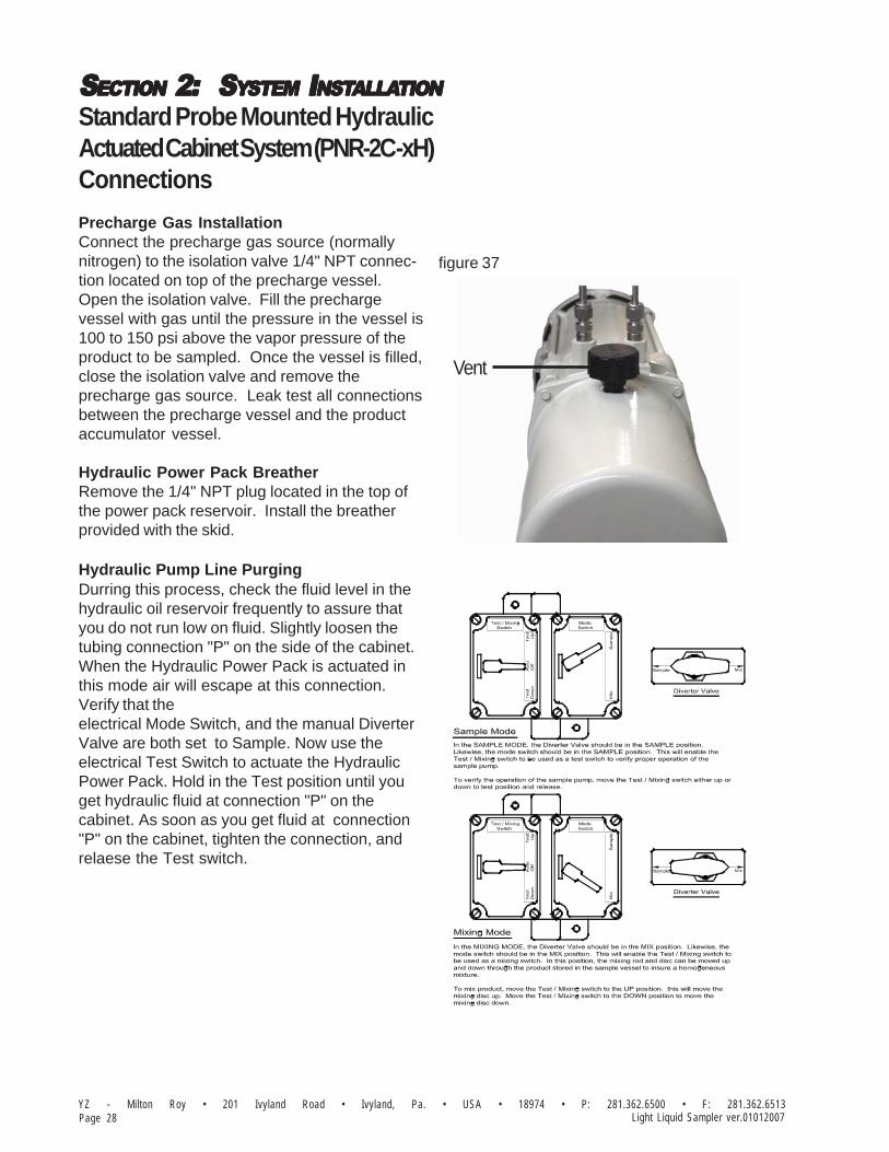
Standard Probe Mounted HydraulicActuated Cabinet System (PNR-2C-xH)Connections
Pump InstallationThe PNR-2 sample pump is designed to bemounted directly to a threaded connection on thepipeline. The probe tubing should be cut suchthat the tip of the probe will be located in thecenter 1/3 of the pipeline after installation. Afterthe pipeline has been depressurized, the threadson the probe body should be taped and dopedand the pump installed into the pipeline connec-tion.
Electrical Connections120 VAC, 60 Hz electrical power should beconnected to the left side opening of the cabinetelectrical enclosure. The power wiring should beconnected to the wires tagged “120 Volt AC”.The hot wire should be connected to the blacksystem wire. The neutral wire should be con-nected to the white system wire. The flow signalshould be connected at this time
Cabinet InstallationThe cabinet should be located as close aspossible to the pipeline. Care should be taken inrouting tubing between the pump and cabinet, toprevent traps, long runs, etc. 1/4" stainlesssteel tubing should be field routed from thebalance valve discharge to the product in con-nection for the five-way cross.
1/4" - 3/8” stainless steel tubing should also befield routed from the sample pump hydraulicsupply and return ports to the cabinet connec-tions. These lines will have to be purged of air,and filled with hydraulic fluid before and pumpactuation can begin.
ISOLATION VALVE
FLOW
(FROM CABINET)HYDRAULIC SUPPLY
SUPPLY PROBE
PRODUCT OUT(TO CABINET)
(FROM CABINET)HYDRAULIC RETURN
Product Out To CabinetConnection "C"
Hydraulic Supply ToCabinet Connection "D"
Hydraulic Return ToCabinet Connection "P"
A
B
20"24"
9"
57"
LEFT SIDE VIEW
15"
20"
P
C
D
figure 35
figure 36
SSSSSECTIONECTIONECTIONECTIONECTION 2: 2: 2: 2: 2: S S S S SYYYYYSTEMSTEMSTEMSTEMSTEM I I I I INSTNSTNSTNSTNSTALLAALLAALLAALLAALLATIONTIONTIONTIONTION
YZ - Milton Roy • 201 Ivyland Road • Ivyland, Pa. • USA • 18974 • P: 281.362.6500 • F: 281.362.6513Page 28 Light Liquid Sampler ver.01012007
Standard Probe Mounted HydraulicActuated Cabinet System (PNR-2C-xH)Connections
Precharge Gas InstallationConnect the precharge gas source (normallynitrogen) to the isolation valve 1/4" NPT connec-tion located on top of the precharge vessel.Open the isolation valve. Fill the prechargevessel with gas until the pressure in the vessel is100 to 150 psi above the vapor pressure of theproduct to be sampled. Once the vessel is filled,close the isolation valve and remove theprecharge gas source. Leak test all connectionsbetween the precharge vessel and the productaccumulator vessel.
Hydraulic Power Pack BreatherRemove the 1/4" NPT plug located in the top ofthe power pack reservoir. Install the breatherprovided with the skid.
Hydraulic Pump Line PurgingDurring this process, check the fluid level in thehydraulic oil reservoir frequently to assure thatyou do not run low on fluid. Slightly loosen thetubing connection "P" on the side of the cabinet.When the Hydraulic Power Pack is actuated inthis mode air will escape at this connection.Verify that theelectrical Mode Switch, and the manual DiverterValve are both set to Sample. Now use theelectrical Test Switch to actuate the HydraulicPower Pack. Hold in the Test position until youget hydraulic fluid at connection "P" on thecabinet. As soon as you get fluid at connection"P" on the cabinet, tighten the connection, andrelaese the Test switch.
figure 37
Vent

SSSSSECTIONECTIONECTIONECTIONECTION 2: 2: 2: 2: 2: S S S S SYYYYYSTEMSTEMSTEMSTEMSTEM I I I I INSTNSTNSTNSTNSTALLAALLAALLAALLAALLATIONTIONTIONTIONTION
Page 29YZ - Milton Roy • 201 Ivyland Road • Ivyland, Pa. • USA • 18974 • P: 281.362.6500 • F: 281.362.6513Light Liquid Sampler ver.01012007
Standard Cabinet MountedHydraulic Actuated System(LPR-2C-xH) Connections
Sample Probe InstallationThe sample probe assembly is designed to bemounted directly to a threaded connection onthe pipeline. The probe should be cut such thatthe tip of the probe will be located in the center1/3 of the pipeline after installation. After thepipeline has been depressurized, the threads onthe probe body should be taped and doped andthe pump installed into the pipeline connection.Location of the probe in the pipeline should be inaccordance with approved sampling standards.It is essential that the probe be located in anarea of the pipeline where the product will behomogeneously mixed. The probe should beinserted to extract the product from the center 1/3of the pipeline. It should then be connected tothe Sample Pump product connection andreturn ports in a manner to assure adequateflow through the connection lines.
Cabinet InstallationThe cabinet should be located as close aspossible to the pipeline. 1/4" stainless steeltubing should also be field routed from thesample probe discharge to the port tagged"product in" on the enclosure, which connects tothe product inlet of the Sample Pump. 1/4"stainless steel tubing should also be field routedfrom the return connection on the cabinet to thelow pressure return port of the pipeline. Careshould be taken in routing this tubing to preventtraps, long runs, etc.
7"8"
PRODUCT IN(FROM PIPELINE 1/4"NPT)
BACK VIEW
PRODUCT LOOP(TO PIPELINE 1/4"NPT)
SUPPLY AIR 100 psi1/4" TUBING
(BY CUSTOMER)
figure 38
SSSSSECTIONECTIONECTIONECTIONECTION 2: 2: 2: 2: 2: S S S S SYYYYYSTEMSTEMSTEMSTEMSTEM I I I I INSTNSTNSTNSTNSTALLAALLAALLAALLAALLATIONTIONTIONTIONTION
YZ - Milton Roy • 201 Ivyland Road • Ivyland, Pa. • USA • 18974 • P: 281.362.6500 • F: 281.362.6513Page 30 Light Liquid Sampler ver.01012007
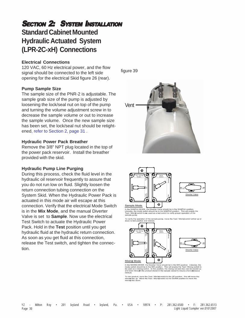
Standard Cabinet MountedHydraulic Actuated System(LPR-2C-xH) Connections
Electrical Connections120 VAC, 60 Hz electrical power, and the flowsignal should be connected to the left sideopening for the electrical Skid figure 26 (rear).
Pump Sample SizeThe sample size of the PNR-2 is adjustable. Thesample grab size of the pump is adjusted byloosening the lock/seal nut on top of the pumpand turning the volume adjustment screw in todecrease the sample volume or out to increasethe sample volume. Once the new sample sizehas been set, the lock/seal nut should be retight-ened, refer to Section 2, page 31 .
Hydraulic Power Pack BreatherRemove the 3/8" NPT plug located in the top ofthe power pack reservoir. Install the breatherprovided with the skid.
Hydraulic Pump Line PurgingDuring this process, check the fluid level in thehydraulic oil reservoir frequently to assure thatyou do not run low on fluid. Slightly loosen thereturn connection tubing connection on theSystem Skid. When the Hydraulic Power Pack isactuated in this mode air will escape at thisconnection. Verify that the electrical Mode Switchis in the Mix Mode, and the manual DiverterValve is set to Sample. Now use the electricalTest Switch to actuate the Hydraulic PowerPack. Hold in the Test position until you gethydraulic fluid at the hydraulic return connection.As soon as you get fluid at this connection,release the Test switch, and tighten the connec-tion.
Vent
figure 39

SSSSSECTIONECTIONECTIONECTIONECTION 2: 2: 2: 2: 2: S S S S SYYYYYSTEMSTEMSTEMSTEMSTEM I I I I INSTNSTNSTNSTNSTALLAALLAALLAALLAALLATIONTIONTIONTIONTION
Page 31YZ - Milton Roy • 201 Ivyland Road • Ivyland, Pa. • USA • 18974 • P: 281.362.6500 • F: 281.362.6513Light Liquid Sampler ver.01012007
Pump Sample Size
The sample size of the PNR-2 Pump is adjust-able. Sample grab size of the pump is adjustedby loosening the 5/16 jam nut on top of the pumpand turning the volume adjustment screw acornnut in to decrease the sample volume or out toincrease the sample volume. Once the newsample size has been set, the jam nut should beretightened, refer to Section 6, pages 63-66, andAppendix, pages 87-90 .
Pump Displacement:Std. 3/8” Plunger .25 - 1.8 cc/StrokeOpt.1/2” Plunger 0.8 - 3.2 cc/StrokeOpt.5/8” Plunger 1.25 - 5.0cc/StrokeOpt.1” Plunger 1.6 - 12.8cc/StrokeThe
figure 40
STROKE SCALE, 3/8" PD PUMP
PNR-2 ACTUATOR CYLINDER
PNR-2 STROKE SCREW ASSY
PNR-2 STROKE SCALE IND
B2-1003
ACTUATION SUPPLY
5/16 FLAT WASHER, SS
MCONN, 1/4T 1/8P, SS
5/16-18 x 5/8" HHCS SS
A1-0003
B2-1007
C0-0017
C0-0098
B2-1002
D5-0020
PD PUMP PACKING
5/16-24 JAM NUT SS
PNR-2 PACKING GLAND NUT
PNR-2 ACORN NUT
A6-0035
B2-1006
C0-0108
B2-1001
SSSSSECTIONECTIONECTIONECTIONECTION 2: 2: 2: 2: 2: S S S S SYYYYYSTEMSTEMSTEMSTEMSTEM I I I I INSTNSTNSTNSTNSTALLAALLAALLAALLAALLATIONTIONTIONTIONTION
YZ - Milton Roy • 201 Ivyland Road • Ivyland, Pa. • USA • 18974 • P: 281.362.6500 • F: 281.362.6513Page 32 Light Liquid Sampler ver.01012007
Notes

SSSSSECTIONECTIONECTIONECTIONECTION 3: F 3: F 3: F 3: F 3: FILLINGILLINGILLINGILLINGILLING THETHETHETHETHE P P P P PRERERERERE-C-C-C-C-CHARGEHARGEHARGEHARGEHARGE V V V V VESSELESSELESSELESSELESSEL
Page 33YZ - Milton Roy • 201 Ivyland Road • Ivyland, Pa. • USA • 18974 • P: 281.362.6500 • F: 281.362.6513Light Liquid Sampler ver.01012007
The purpose of the precharge system is to keepthe sampled product in a liquid phase. This isaccomplished by maintaining a prechargepressure on top of the accumulator vesselpiston. The precharge vessel provides additionalvolume to the precharge system, which mini-mizes the pressure increase within the productaccumulator as it fills.
Prior to placing the sampler into service, it isnecessary that the precharge system becharged to a pressure at least 100 psi greaterthan the product vapor pressure. For example, ifa product with a vapor pressure of 300 psi isbeing sampled, a precharge pressure of 400 psiwould be required. Servicing the prechargevessel is done using the isolation valve locatedon top of the precharge vessel. Please note thatthe valve isolates the precharge system from theatmosphere, and does not separate theprecharge vessel from the accumulator vessel.Also, the precharge vessel is shipped with 10 psiof blanket pressure. Normally this Pre-Chargevessel should only need to be filled one time atthe installation of the sampler system, as the gasis not consumed in the sampling process.
CACACACACAUTION:UTION:UTION:UTION:UTION:Take necessary precautions when working withNitrogen Vessels, as the high pressure containedwithin is dangerous Additionally, all personnelshould wear protective clothing, and use equipmentas recommended by the manufacturer during thistime. If you are uncertain about any aspect of theNitrogen Vessel itself, you should contact themanufacturer of your Vessel prior to proceeding.
Filling the Vessel1. Connect the precharge gas source (normally
nitrogen) to the isolation valve 1/4" NPT connection located on top of the precharge vessel, refer to page 93.
2. Open the isolation valve.
3. Fill the precharge vessel with gas until the pressure in the vessel is 100 to 150 psi above the vapor pressure of the product to be sampled.
4. Once the vessel is filled, close the isolation valve and remove the precharge gas source.
5. Leak test all connections between the precharge vessel and the product accumu- lator vessel.
6. Continue through the remaining procedures inthis manual.

SSSSSECTIONECTIONECTIONECTIONECTION 3: F 3: F 3: F 3: F 3: FILLINGILLINGILLINGILLINGILLING THETHETHETHETHE P P P P PRERERERERE-C-C-C-C-CHARGEHARGEHARGEHARGEHARGE V V V V VESSELESSELESSELESSELESSEL
YZ - Milton Roy • 201 Ivyland Road • Ivyland, Pa. • USA • 18974 • P: 281.362.6500 • F: 281.362.6513Page 34 Light Liquid Sampler ver.01012007
Notes

YZ Systems, Inc. • 3101 Pollok Drive • Conroe, Texas • USA • 77303 • P: 936.788.5593 • F: 936.788.5720Page 35PNR-2S-(1.5,3,5)P-3B ver.08292005
SSSSSECTIONECTIONECTIONECTIONECTION 4: 4: 4: 4: 4: S S S S SYYYYYSTEMSTEMSTEMSTEMSTEM C C C C CONTRONTRONTRONTRONTROLOLOLOLOL & E & E & E & E & ELECTRLECTRLECTRLECTRLECTRONICSONICSONICSONICSONICSSSSSSECTIONECTIONECTIONECTIONECTION 4: 4: 4: 4: 4: S S S S SYYYYYSTEMSTEMSTEMSTEMSTEM C C C C CONTRONTRONTRONTRONTROLOLOLOLOL & E & E & E & E & ELECTRLECTRLECTRLECTRLECTRONICSONICSONICSONICSONICS
Overview
The electronic control package provided withyour sampling system may consist of a simplesolenoid which interfaces with an outside controlsystem to operate, or it may be a self containedcontroller, or anything in between. The controlsystem must send a mimimum 3 second actua-tion pulse to the sample pump. This 3 secondduration allows sufficient time to stroke thesample pump and retrieve a single sample.
SAFETY NOSAFETY NOSAFETY NOSAFETY NOSAFETY NOTESTESTESTESTES• Always use extreme care when performing mainte-
nance on Sampling Systems. Always takenecessary measures to assure that electricalclassification in the area is considered, before,and during all repairs, and that necessary stepsare taken to maintain proper electrical proceduresfor the classification of the area.
All electronics are housed in explosion proofenclosures and are rated for use in Class I,Division 1, Groups C and D hazardous locations,or are Intrinsically Safe for installation in Class I,Division 1, Groups C and D hazardous locations.
By properly adjusting both the sample size andthe sample frequency, the sample vessel will fillto 80% capacity at the end of the sample period.
Refer to apropriate control option wiring informa-tion on the following pages, and to Section 5 forProgramming for Operation details.

YZ Systems, Inc. • 3101 Pollok Drive • Conroe, Texas • USA • 77303 • P: 936.788.5593 • F: 936.788.5720Page 36 PNR-2S-(1.5,3,5)P-3B ver.08292005
SSSSSECTIONECTIONECTIONECTIONECTION 4: 4: 4: 4: 4: S S S S SYYYYYSTEMSTEMSTEMSTEMSTEM C C C C CONTRONTRONTRONTRONTROLOLOLOLOL & E & E & E & E & ELECTRLECTRLECTRLECTRLECTRONICSONICSONICSONICSONICS
Pneumatic Actuated “- 0” Control Option
The electronic control package provided thissampling system consist of a simple solenoidwhich interfaces with an outside customersupplied power supply and control system tooperate it. The control system must send amimimum 3 second actuation pulse to thesolenoid. This 3 second duration allows sufficienttime for the solenoid to actuate the sample pumpand retrieve a single sample.
Proper programing of the customer suppliedcontrol unit should allow the sample vessel to fillto 80% capacity at the end of the sample period.
CUSTOMER SUPPLIED
SWITCHED VOLTAGE
-0A = 24 VDC
-0B = 120 VAC
(SEE NOTE #1)
1. VOLTAGE SIGNAL MUST HAVE A
MINIMUM DWELL OF 3 SECONDS.
figure 41

YZ Systems, Inc. • 3101 Pollok Drive • Conroe, Texas • USA • 77303 • P: 936.788.5593 • F: 936.788.5720Page 37PNR-2S-(1.5,3,5)P-3B ver.08292005
SSSSSECTIONECTIONECTIONECTIONECTION 4: 4: 4: 4: 4: S S S S SYYYYYSTEMSTEMSTEMSTEMSTEM C C C C CONTRONTRONTRONTRONTROLOLOLOLOL & E & E & E & E & ELECTRLECTRLECTRLECTRLECTRONICSONICSONICSONICSONICS
Pneumatic Actuated “- 1A” (24 VDC) Control Option
The electronic control package provided with this sampling system consists of a solid state TimeDelay Relay (TDR), and a solenoid. The TDR converts a continuous voltage signal into a 3 secondvoltage output to the solenoid, everytime a contact closure occurs. This 3 second duration allowssufficient time to actuate the sample pump and retrieve a single sample.
SAFETY NOSAFETY NOSAFETY NOSAFETY NOSAFETY NOTESTESTESTESTES• Always use extreme care when performing maintenance on Sampling Systems. Always take necessary
measures to assure that electrical classification in the area is considered, before, and during all repairs,and that necessary steps are taken to maintain proper electrical procedures for the classification of thearea.
The control package requires the user to provide 24 VDC at terminals 2 and 3. You are also re-quired to provide dry contacts at terminals 2 and 6, each time the pump should be actuated. Allelectronics in this package are housed in explosion proof enclosures and are rated for use in ClassI, Division 1, Groups C and D hazardous locations.
figure 42
PARTS LIST
LOCATION QTY PART NUMBER DESCRIPTION
K1 1 E0-6007 TIME DELAY RELAY
RI 1 G1-0112 RESISTOR SSEMBLY
D1 1 E0-2003 DIODE

YZ Systems, Inc. • 3101 Pollok Drive • Conroe, Texas • USA • 77303 • P: 936.788.5593 • F: 936.788.5720Page 38 PNR-2S-(1.5,3,5)P-3B ver.08292005
SSSSSECTIONECTIONECTIONECTIONECTION 4: 4: 4: 4: 4: S S S S SYYYYYSTEMSTEMSTEMSTEMSTEM C C C C CONTRONTRONTRONTRONTROLOLOLOLOL & E & E & E & E & ELECTRLECTRLECTRLECTRLECTRONICSONICSONICSONICSONICS
Pneumatic Actuated “- 1B” (120 VAC) Control Option
The electronic control package provided with this sampling system consists of a solid state TimeDelay Relay (TDR), and a solenoid. The TDR converts a continuous voltage signal into a 3 secondvoltage output to the solenoid, everytime a contact closure occurs. This 3 second duration allowssufficient time to actuate the sample pump and retrieve a single sample.
SAFETY NOSAFETY NOSAFETY NOSAFETY NOSAFETY NOTESTESTESTESTES• Always use extreme care when performing maintenance on Sampling Systems. Always take necessary
measures to assure that electrical classification in the area is considered, before, and during all repairs,and that necessary steps are taken to maintain proper electrical procedures for the classification of thearea.
The control package requires you to provide 120 VAC at terminals 2 and 3. You are also required toprovide dry contacts at terminals 2 and 6, in order to stroke the pump. All electronics are housed inexplosion proof enclosures and are rated for use in Class I, Division 1, Groups C and D hazardouslocations. Refer to Section 5 for programming information.
figure 43

YZ Systems, Inc. • 3101 Pollok Drive • Conroe, Texas • USA • 77303 • P: 936.788.5593 • F: 936.788.5720Page 39PNR-2S-(1.5,3,5)P-3B ver.08292005
SSSSSECTIONECTIONECTIONECTIONECTION 4: 4: 4: 4: 4: S S S S SYYYYYSTEMSTEMSTEMSTEMSTEM C C C C CONTRONTRONTRONTRONTROLOLOLOLOL & E & E & E & E & ELECTRLECTRLECTRLECTRLECTRONICSONICSONICSONICSONICS
Pneumatic Actuated “- 4A” (24VDC / 4-20 mA) Control Option
The electronic control package provided with this sampling system consists of a solid state Z-200controller, opto relay, and time delay relay, to fire a solenoid. The Z-200 utilizes customer pro-grammed parameters and the customer supplied 4-20mA flow control signal to converts a continu-ous voltage signal into a 3 second voltage output to the solenoid, everytime a sample is required ofthe system. This 3 second duration allows sufficient time to stroke the sample pump and retrieve asingle sample.
SAFETY NOSAFETY NOSAFETY NOSAFETY NOSAFETY NOTESTESTESTESTES• Always use extreme care when performing maintenance on Sampling Systems. Always take necessary
measures to assure that electrical classification in the area is considered, before, and during all repairs,and that necessary steps are taken to maintain proper electrical procedures for the classification of thearea.
This control package requires you to provide 24 VDC at TS1 terminals 1 and 2(Z-200 terminal #7 ). You are also required to provide a 4-20 mA flow control signal at TS1 terminals 5 and 6 (N-200terminal #4 & #5), in order to stroke the pump. All electronics are rated for use in Class I, Division 1,Groups C and D hazardous locations. Refer to Section 5 for programming information, andAppendix A for Wiring Control Document.
figure 44
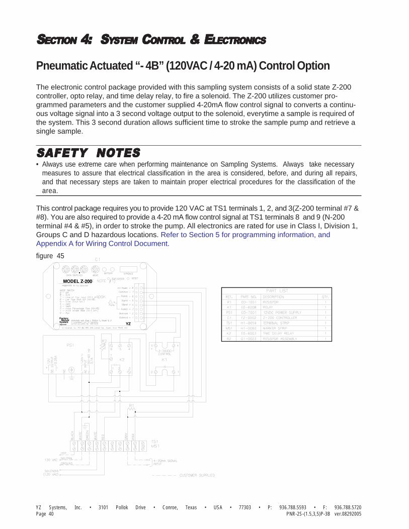
YZ Systems, Inc. • 3101 Pollok Drive • Conroe, Texas • USA • 77303 • P: 936.788.5593 • F: 936.788.5720Page 40 PNR-2S-(1.5,3,5)P-3B ver.08292005
SSSSSECTIONECTIONECTIONECTIONECTION 4: 4: 4: 4: 4: S S S S SYYYYYSTEMSTEMSTEMSTEMSTEM C C C C CONTRONTRONTRONTRONTROLOLOLOLOL & E & E & E & E & ELECTRLECTRLECTRLECTRLECTRONICSONICSONICSONICSONICS
Pneumatic Actuated “- 4B” (120VAC / 4-20 mA) Control Option
The electronic control package provided with this sampling system consists of a solid state Z-200controller, opto relay, and time delay relay, to fire a solenoid. The Z-200 utilizes customer pro-grammed parameters and the customer supplied 4-20mA flow control signal to converts a continu-ous voltage signal into a 3 second voltage output to the solenoid, everytime a sample is required ofthe system. This 3 second duration allows sufficient time to stroke the sample pump and retrieve asingle sample.
SAFETY NOSAFETY NOSAFETY NOSAFETY NOSAFETY NOTESTESTESTESTES• Always use extreme care when performing maintenance on Sampling Systems. Always take necessary
measures to assure that electrical classification in the area is considered, before, and during all repairs,and that necessary steps are taken to maintain proper electrical procedures for the classification of thearea.
This control package requires you to provide 120 VAC at TS1 terminals 1, 2, and 3(Z-200 terminal #7 ). You are also required to provide a 4-20 mA flow control signal at TS1 terminals 8 and 9 (N-200terminal #4 & #5), in order to stroke the pump. All electronics are rated for use in Class I, Division 1,Groups C and D hazardous locations. Refer to Section 5 for programming information, andAppendix A for Wiring Control Document.
figure 45
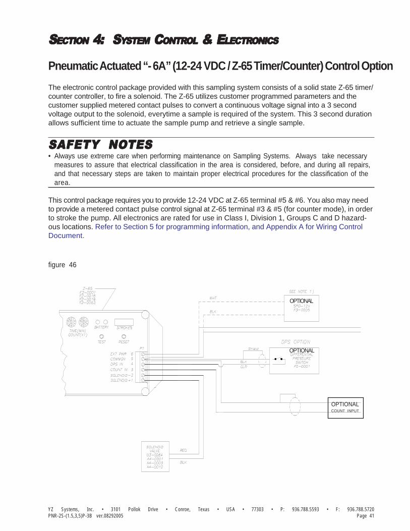
YZ Systems, Inc. • 3101 Pollok Drive • Conroe, Texas • USA • 77303 • P: 936.788.5593 • F: 936.788.5720Page 41PNR-2S-(1.5,3,5)P-3B ver.08292005
SSSSSECTIONECTIONECTIONECTIONECTION 4: 4: 4: 4: 4: S S S S SYYYYYSTEMSTEMSTEMSTEMSTEM C C C C CONTRONTRONTRONTRONTROLOLOLOLOL & E & E & E & E & ELECTRLECTRLECTRLECTRLECTRONICSONICSONICSONICSONICS
Pneumatic Actuated “- 6A” (12-24 VDC / Z-65 Timer/Counter) Control Option
The electronic control package provided with this sampling system consists of a solid state Z-65 timer/counter controller, to fire a solenoid. The Z-65 utilizes customer programmed parameters and thecustomer supplied metered contact pulses to convert a continuous voltage signal into a 3 secondvoltage output to the solenoid, everytime a sample is required of the system. This 3 second durationallows sufficient time to actuate the sample pump and retrieve a single sample.
SAFETY NOSAFETY NOSAFETY NOSAFETY NOSAFETY NOTESTESTESTESTES• Always use extreme care when performing maintenance on Sampling Systems. Always take necessary
measures to assure that electrical classification in the area is considered, before, and during all repairs,and that necessary steps are taken to maintain proper electrical procedures for the classification of thearea.
This control package requires you to provide 12-24 VDC at Z-65 terminal #5 & #6. You also may needto provide a metered contact pulse control signal at Z-65 terminal #3 & #5 (for counter mode), in orderto stroke the pump. All electronics are rated for use in Class I, Division 1, Groups C and D hazard-ous locations. Refer to Section 5 for programming information, and Appendix A for Wiring ControlDocument.
figure 46
OPTIONAL
OPTIONAL
OPTIONALCOUNT INPUT

YZ Systems, Inc. • 3101 Pollok Drive • Conroe, Texas • USA • 77303 • P: 936.788.5593 • F: 936.788.5720Page 42 PNR-2S-(1.5,3,5)P-3B ver.08292005
SSSSSECTIONECTIONECTIONECTIONECTION 4: 4: 4: 4: 4: S S S S SYYYYYSTEMSTEMSTEMSTEMSTEM C C C C CONTRONTRONTRONTRONTROLOLOLOLOL & E & E & E & E & ELECTRLECTRLECTRLECTRLECTRONICSONICSONICSONICSONICS
Pneumatic Actuated “- 6B” (120VAC / Z-65 Timer/Counter) Control Option
The electronic control package provided with this sampling system consists of a solid state Z-65 timer/counter controller, to fire a solenoid. The Z-65 utilizes customer programmed parameters and thecustomer supplied metered contact pulses to convert a continuous voltage signal into a 3 secondvoltage output to the solenoid, everytime a sample is required of the system. This 3 second durationallows sufficient time to actuate the sample pump and retrieve a single sample.
SAFETY NOSAFETY NOSAFETY NOSAFETY NOSAFETY NOTESTESTESTESTES• Always use extreme care when performing maintenance on Sampling Systems. Always take necessary
measures to assure that electrical classification in the area is considered, before, and during all repairs,and that necessary steps are taken to maintain proper electrical procedures for the classification of thearea.
This control package requires you to provide 120 VAC at TS1 terminals 1, 2, and 3. You also may needto provide customer supplied metered contact pulses at Z-65 terminal #3 & #5 (counter mode), inorder to stroke the pump. All electronics are rated for use in Class I, Division 1, Groups C and Dhazardous locations. Refer to Section 5 for programming information, and Appendix A for WiringControl Document.
figure 47

YZ Systems, Inc. • 3101 Pollok Drive • Conroe, Texas • USA • 77303 • P: 936.788.5593 • F: 936.788.5720Page 43PNR-2S-(1.5,3,5)P-3B ver.08292005
SSSSSECTIONECTIONECTIONECTIONECTION 4: 4: 4: 4: 4: S S S S SYYYYYSTEMSTEMSTEMSTEMSTEM C C C C CONTRONTRONTRONTRONTROLOLOLOLOL & E & E & E & E & ELECTRLECTRLECTRLECTRLECTRONICSONICSONICSONICSONICS
Pneumatic Actuated “- 6M (12-24 VDC / Z-65 Timer/Counter w/PIM Card)Control Option
The electronic control package provided with this sampling system consists of a solid state Z-65timer/counter controller, to fire a solenoid. The Z-65 utilizes customer programmed parameters andthe customer supplied metered contact pulses to convert a continuous voltage signal into a 3 sec-ond voltage output to the solenoid, everytime a sample is required of the system. This 3 secondduration allows sufficient time to actuate the sample pump and retrieve a single sample.
SAFETY NOSAFETY NOSAFETY NOSAFETY NOSAFETY NOTESTESTESTESTES• Always use extreme care when performing maintenance on Sampling Systems. Always take necessary
measures to assure that electrical classification in the area is considered, before, and during all repairs,and that necessary steps are taken to maintain proper electrical procedures for the classification of thearea.
This control package requires you to provide 12-24 VDC at Z-65 terminal #5 & #6. You also may needto provide a Magnetic pick-up pulse control signal at PIM-100 terminal #1 & #2 (for meter countermode), in order to stroke the pump. All electronics are rated for use in Class I, Division 1, Groups Cand D hazardous locations. Refer to Section 5 for programming information, and Appendix A forWiring Control Document.
figure 48
OPTIONAL
OPTIONAL
OPTIONALCOUNT INPUT
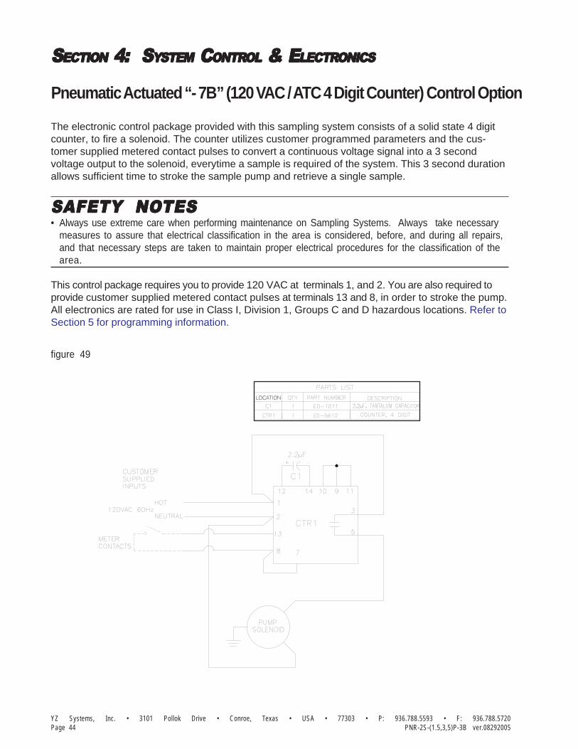
YZ Systems, Inc. • 3101 Pollok Drive • Conroe, Texas • USA • 77303 • P: 936.788.5593 • F: 936.788.5720Page 44 PNR-2S-(1.5,3,5)P-3B ver.08292005
SSSSSECTIONECTIONECTIONECTIONECTION 4: 4: 4: 4: 4: S S S S SYYYYYSTEMSTEMSTEMSTEMSTEM C C C C CONTRONTRONTRONTRONTROLOLOLOLOL & E & E & E & E & ELECTRLECTRLECTRLECTRLECTRONICSONICSONICSONICSONICS
Pneumatic Actuated “- 7B” (120 VAC / ATC 4 Digit Counter) Control Option
The electronic control package provided with this sampling system consists of a solid state 4 digitcounter, to fire a solenoid. The counter utilizes customer programmed parameters and the cus-tomer supplied metered contact pulses to convert a continuous voltage signal into a 3 secondvoltage output to the solenoid, everytime a sample is required of the system. This 3 second durationallows sufficient time to stroke the sample pump and retrieve a single sample.
SAFETY NOSAFETY NOSAFETY NOSAFETY NOSAFETY NOTESTESTESTESTES• Always use extreme care when performing maintenance on Sampling Systems. Always take necessary
measures to assure that electrical classification in the area is considered, before, and during all repairs,and that necessary steps are taken to maintain proper electrical procedures for the classification of thearea.
This control package requires you to provide 120 VAC at terminals 1, and 2. You are also required toprovide customer supplied metered contact pulses at terminals 13 and 8, in order to stroke the pump.All electronics are rated for use in Class I, Division 1, Groups C and D hazardous locations. Refer toSection 5 for programming information.
figure 49

YZ Systems, Inc. • 3101 Pollok Drive • Conroe, Texas • USA • 77303 • P: 936.788.5593 • F: 936.788.5720Page 45PNR-2S-(1.5,3,5)P-3B ver.08292005
SSSSSECTIONECTIONECTIONECTIONECTION 4: 4: 4: 4: 4: S S S S SYYYYYSTEMSTEMSTEMSTEMSTEM C C C C CONTRONTRONTRONTRONTROLOLOLOLOL & E & E & E & E & ELECTRLECTRLECTRLECTRLECTRONICSONICSONICSONICSONICS
Hydraulic Actuated “- 1B” (120 VAC) Control Option
TSY S SE M
The electronic control package provided with this sampling system consists of a solid state TimeDelay Relay (TDR). The TDR converts a continuous voltage signal into a 3 second voltage output tothe hydraulic power pack, everytime a contact closure occurs. This 3 second duration allowssufficient time to actuate the sample pump and retrieve a single sample.
SAFETY NOSAFETY NOSAFETY NOSAFETY NOSAFETY NOTESTESTESTESTES• Always use extreme care when performing maintenance on Sampling Systems. Always take necessary
measures to assure that electrical classification in the area is considered, before, and during all repairs,and that necessary steps are taken to maintain proper electrical procedures for the classification of thearea.
The control package requires you to provide 120 VAC at terminals 2 and 3. You are also required toprovide dry contacts at terminals 2 and 6, in order to stroke the pump. All electronics are housed inexplosion proof enclosures and are rated for use in Class I, Division 1, Groups C and D hazardous,locations. Refer to Section 5 for programming information.
figure 50

YZ Systems, Inc. • 3101 Pollok Drive • Conroe, Texas • USA • 77303 • P: 936.788.5593 • F: 936.788.5720Page 46 PNR-2S-(1.5,3,5)P-3B ver.08292005
SSSSSECTIONECTIONECTIONECTIONECTION 4: 4: 4: 4: 4: S S S S SYYYYYSTEMSTEMSTEMSTEMSTEM C C C C CONTRONTRONTRONTRONTROLOLOLOLOL & E & E & E & E & ELECTRLECTRLECTRLECTRLECTRONICSONICSONICSONICSONICS
Hydraulic Actuated “- 4B” (120VAC / 4-20mA) Control Option
The electronic control package provided with this sampling system consists of a solid state Z-200controller, power supply/converter, opto relay, and time delay relay, to fire the hydraulic power pack.The Z-200 utilizes customer programmed parameters and the customer supplied 4-20mA flowcontrol signal to converts a continuous voltage signal into a 3 second voltage output to the hydraulicpower pack, everytime a sample is required of the system. This 3 second duration allows sufficienttime to stroke the sample pump and retrieve a single sample.
SAFETY NOSAFETY NOSAFETY NOSAFETY NOSAFETY NOTESTESTESTESTES• Always use extreme care when performing maintenance on Sampling Systems. Always take necessary
measures to assure that electrical classification in the area is considered, before, and during all repairs,and that necessary steps are taken to maintain proper electrical procedures for the classification of thearea.
This control package requires you to provide 120 VAC at TS1 terminals 1, 2, and 3. You are also re-quired to provide a 4-20 mA flow control signal at TS1 terminals 8 and 9, in order to stroke the pump.All electronics are rated for use in Class I, Division 1, Groups C and D hazardous locations. Refer toSection 5 for programming information, and Appendix A for Wiring Control Document.
figure 51
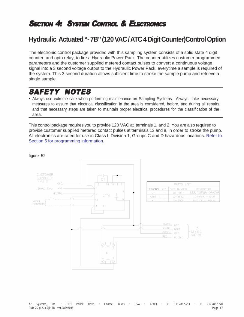
YZ Systems, Inc. • 3101 Pollok Drive • Conroe, Texas • USA • 77303 • P: 936.788.5593 • F: 936.788.5720Page 47PNR-2S-(1.5,3,5)P-3B ver.08292005
SSSSSECTIONECTIONECTIONECTIONECTION 4: 4: 4: 4: 4: S S S S SYYYYYSTEMSTEMSTEMSTEMSTEM C C C C CONTRONTRONTRONTRONTROLOLOLOLOL & E & E & E & E & ELECTRLECTRLECTRLECTRLECTRONICSONICSONICSONICSONICS
The electronic control package provided with this sampling system consists of a solid state 4 digitcounter, and opto relay, to fire a Hydraulic Power Pack. The counter utilizes customer programmedparameters and the customer supplied metered contact pulses to convert a continuous voltagesignal into a 3 second voltage output to the Hydraulic Power Pack, everytime a sample is required ofthe system. This 3 second duration allows sufficient time to stroke the sample pump and retrieve asingle sample.
SAFETY NOSAFETY NOSAFETY NOSAFETY NOSAFETY NOTESTESTESTESTES• Always use extreme care when performing maintenance on Sampling Systems. Always take necessary
measures to assure that electrical classification in the area is considered, before, and during all repairs,and that necessary steps are taken to maintain proper electrical procedures for the classification of thearea.
This control package requires you to provide 120 VAC at terminals 1, and 2. You are also required toprovide customer supplied metered contact pulses at terminals 13 and 8, in order to stroke the pump.All electronics are rated for use in Class I, Division 1, Groups C and D hazardous locations. Refer toSection 5 for programming information.
Hydraulic Actuated “- 7B” (120 VAC / ATC 4 Digit Counter)Control Option
figure 52

YZ Systems, Inc. • 3101 Pollok Drive • Conroe, Texas • USA • 77303 • P: 936.788.5593 • F: 936.788.5720Page 48 PNR-2S-(1.5,3,5)P-3B ver.08292005
SSSSSECTIONECTIONECTIONECTIONECTION 4: 4: 4: 4: 4: S S S S SYYYYYSTEMSTEMSTEMSTEMSTEM C C C C CONTRONTRONTRONTRONTROLOLOLOLOL & E & E & E & E & ELECTRLECTRLECTRLECTRLECTRONICSONICSONICSONICSONICS
Notes

SSSSSECTIONECTIONECTIONECTIONECTION 5: 5: 5: 5: 5: P P P P PRRRRROGRAMMINGOGRAMMINGOGRAMMINGOGRAMMINGOGRAMMING FORFORFORFORFOR O O O O OPERAPERAPERAPERAPERATIONTIONTIONTIONTION
Page 49YZ - Milton Roy • 201 Ivyland Road • Ivyland, Pa. • USA • 18974 • P: 281.362.6500 • F: 281.362.6513Light Liquid Sampler ver.01012007
The Light Liquid sampling systems are designedto sample light liquid hydrocarbons. Thousandsof individual samples are captured and combinedto develop a representative, composite sample ofthe flowing pipeline.
Operation of the sampling system centersaround the following primary components: theSample Pump, the Product Accumulator Vessel,the Precharge Gas Vessel, and the ElectronicControl System. The following pages providespecific details for setting up your controller foroperation.
The sampling system operates on a simpleconcept. When the system receives a properflow signal (by others), the electronic control unitenergizes either a solenoid valve, or a HydraulicPower Pack. Energizing the solenoid valve, orHydraulic Power Pack allows a pressurizedpulse into the actuation cylinder of the samplepump, which in turn causes the pump to stroke.When the pump strokes, a small sample isdisplaced into the product accumulator vessel.Once the solenoid valve, or Hydraulic PowerPack is de-energized, the sample pump plungerreturns to its normal position. This action allowsa new sample into the pump.
The purpose of the YZ light liquid hydrocarbonsampling system is to capture and maintain arepresentative liquid sample of the pipelineproduct. The sampled product is maintained in aliquid phase by the product accumulator vessel’sfree floating piston and the precharge gas sys-tem. In order for the system to function properly,pipeline product must be single phase, liquidproduct.
By properly adjusting both the sample size andthe sample frequency, the sample vessel will fillto 80% capacity at the end of the sample period.
Setting Operator Input Parameters
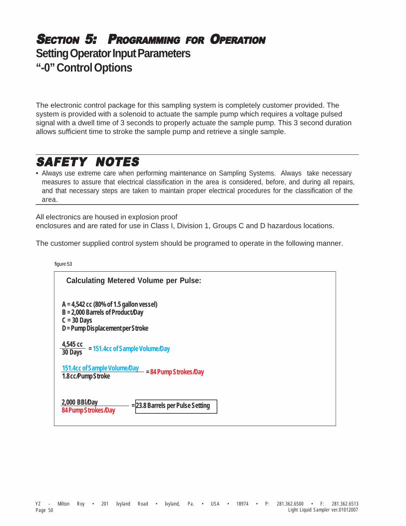
SSSSSECTIONECTIONECTIONECTIONECTION 5: 5: 5: 5: 5: P P P P PRRRRROGRAMMINGOGRAMMINGOGRAMMINGOGRAMMINGOGRAMMING FORFORFORFORFOR O O O O OPERAPERAPERAPERAPERATIONTIONTIONTIONTION
YZ - Milton Roy • 201 Ivyland Road • Ivyland, Pa. • USA • 18974 • P: 281.362.6500 • F: 281.362.6513Page 50 Light Liquid Sampler ver.01012007
Setting Operator Input Parameters“-0” Control Options
The electronic control package for this sampling system is completely customer provided. Thesystem is provided with a solenoid to actuate the sample pump which requires a voltage pulsedsignal with a dwell time of 3 seconds to properly actuate the sample pump. This 3 second durationallows sufficient time to stroke the sample pump and retrieve a single sample.
SAFETY NOSAFETY NOSAFETY NOSAFETY NOSAFETY NOTESTESTESTESTES• Always use extreme care when performing maintenance on Sampling Systems. Always take necessary
measures to assure that electrical classification in the area is considered, before, and during all repairs,and that necessary steps are taken to maintain proper electrical procedures for the classification of thearea.
All electronics are housed in explosion proofenclosures and are rated for use in Class I, Division 1, Groups C and D hazardous locations.
The customer supplied control system should be programed to operate in the following manner.
figure 53
Calculating Metered Volume per Pulse:
A = 4,542 cc (80% of 1.5 gallon vessel)B = 2,000 Barrels of Product/DayC = 30 DaysD = Pump Displacement per Stroke
4,545 cc30 Days
151.4cc of Sample Volume/Day1.8 cc/Pump Stroke
= 151.4cc of Sample Volume/Day
= 84 Pump Strokes/Day
2,000 BBl/Day84 Pump Strokes/Day
= 23.8 Barrels per Pulse Setting

SSSSSECTIONECTIONECTIONECTIONECTION 5: 5: 5: 5: 5: P P P P PRRRRROGRAMMINGOGRAMMINGOGRAMMINGOGRAMMINGOGRAMMING FORFORFORFORFOR O O O O OPERAPERAPERAPERAPERATIONTIONTIONTIONTION
Page 51YZ - Milton Roy • 201 Ivyland Road • Ivyland, Pa. • USA • 18974 • P: 281.362.6500 • F: 281.362.6513Light Liquid Sampler ver.01012007
Setting Operator Input Parameters“-1” Control Options
The proportional to flow control function is actually performed by another customer owned flow monitoringdevice, like a flow computer. The set up of this other device must be done in conjunction with the set up ofthe sampler system in such a manner, that the proper amount of sample will be gathered during theduration of the sample cycle, and to assure that the integrity of the proportional relationship between thegathered sample, and the flowing volume in the pipeline is maintained.
The maximum amount of sample that can be safely placed in the accumulator vessel is 80% of the totalvessel volume. There are two ways to arrive at the settings for the Proportional to Flow Control.
Sampler Control Set-up Option #1This method is based on the peremise that the Metered Volume per pulse value in the flow monitor-ing device, is already set to a predetermined value by the customer.
Calculate the pump displacement setting using the following formula:
Pump Displacement Setting = D x E B x C
Where, B = Average Flow rate (Gal/day or BBL/day)
C = Sample Cycle (days)
D = Metered volume per pulse (Gal/pulse or BBL/pulse)
E = 80% sample accumulator volume (cc)For 1.5 gallon accumulators, E = 4,542 ccrefer to Example #1, figure 54, page 52.
The pump setting must be within range of 0.25 to 1.8 cc / stroke, refer to section 2, page 31, forsetting the pump displacement.

SSSSSECTIONECTIONECTIONECTIONECTION 5: 5: 5: 5: 5: P P P P PRRRRROGRAMMINGOGRAMMINGOGRAMMINGOGRAMMINGOGRAMMING FORFORFORFORFOR O O O O OPERAPERAPERAPERAPERATIONTIONTIONTIONTION
YZ - Milton Roy • 201 Ivyland Road • Ivyland, Pa. • USA • 18974 • P: 281.362.6500 • F: 281.362.6513Page 52 Light Liquid Sampler ver.01012007
figure 54
Example #1
Calculating Pump Setting:
B = 2,000 Barrels of Product/DayC = 30 DaysD = 10 Barrels/pulseE = 4,542 cc (80% of 1.5 gallon vessel)
(10 Barrels/pulse) x(4,542 cc)(2,000Barrels/day) x (30 Days) = .75 cc/Stroke Pump Setting
Example #2figure 55
Calculating Metered Volume per Pulse:
A = 4,542 cc (80% of 1.53 gallon vessel)B = 2,000 Barrels of Product/DayC = 30 DaysD = Pump Displacement per Stroke
4,545 cc30 Days
151.4cc of Sample Volume/Day1.8 cc/Pump Stroke
= 151.4cc of Sample Volume/Day
= 84 Pump Strokes/Day
2,000 BBl/Day84 Pump Strokes/Day
= 23.8 Barrels per Pulse Setting
Setting Operator Input Parameters“-1” Control Options

SSSSSECTIONECTIONECTIONECTIONECTION 5: 5: 5: 5: 5: P P P P PRRRRROGRAMMINGOGRAMMINGOGRAMMINGOGRAMMINGOGRAMMING FORFORFORFORFOR O O O O OPERAPERAPERAPERAPERATIONTIONTIONTIONTION
Page 53YZ - Milton Roy • 201 Ivyland Road • Ivyland, Pa. • USA • 18974 • P: 281.362.6500 • F: 281.362.6513Light Liquid Sampler ver.01012007
Setting Operator Input Parameters“-4” Control Options
In this mode of operation, the Z-200 uses operator inputs inconjunction with the 4-20mA flow input to vary the time thatwill transpire between pump strokes.
A. Adjust the pump volume adjustment screw to desireddisplacement setting.
In order for the Z-200 controller to operate in theproportional-to-flow mode of operation it will benecessary to enter the following parameters:
B. Loss of flow input (XX.X min) mode #7 default 20.0 minutes.
The loss of flow input setting is a predetermined amount oftime that the operator would like to see transpire betweenpump strokes in the event that the 4-20mA flow input signalis lost.
To set the loss of flow input1. Set the mode switch to position #7.2. Set the data switches to the desired time in minutes XX.X minutes.
Example: 20 minutes = 20.0
3. Depress the enter switch to load the value into memory.
NOTE: the green LED will flash if entry is accepted; the redLED will flash if not accepted.
Proportional To Flow Controller Programming
MutualSystemApproved
Factory
DATA SWITCHES
MODE
figure 56
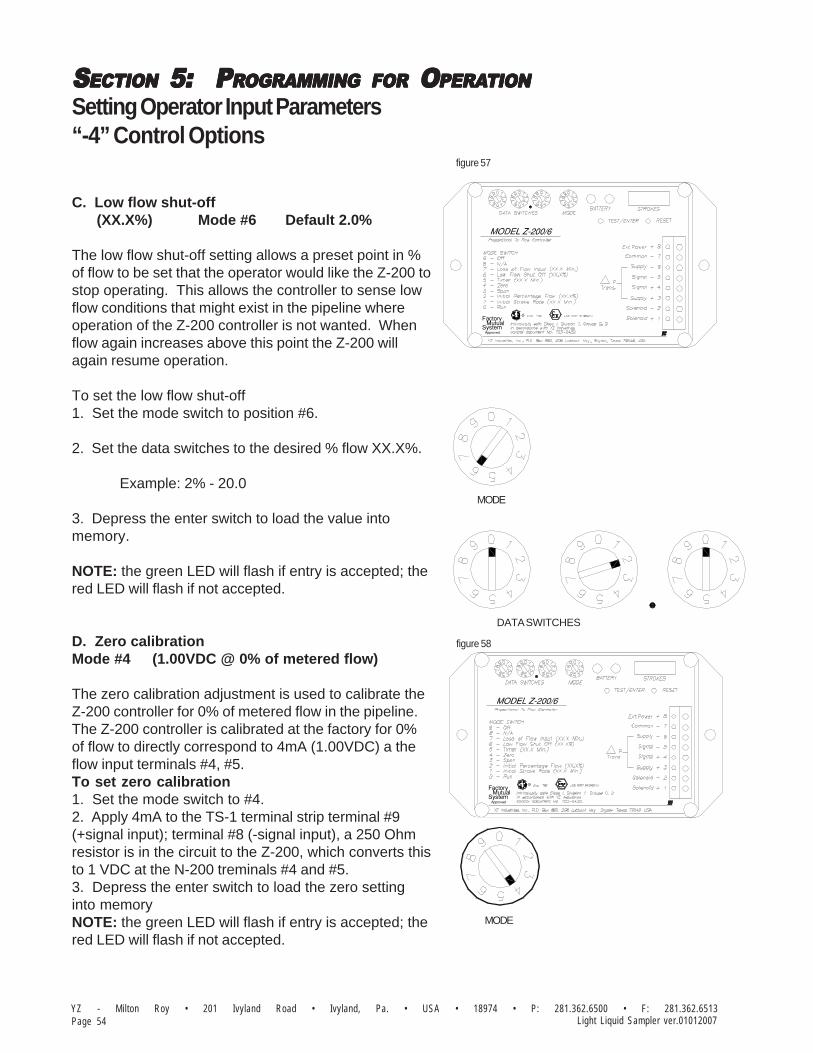
SSSSSECTIONECTIONECTIONECTIONECTION 5: 5: 5: 5: 5: P P P P PRRRRROGRAMMINGOGRAMMINGOGRAMMINGOGRAMMINGOGRAMMING FORFORFORFORFOR O O O O OPERAPERAPERAPERAPERATIONTIONTIONTIONTION
YZ - Milton Roy • 201 Ivyland Road • Ivyland, Pa. • USA • 18974 • P: 281.362.6500 • F: 281.362.6513Page 54 Light Liquid Sampler ver.01012007
Setting Operator Input Parameters“-4” Control Options
C. Low flow shut-off (XX.X%) Mode #6 Default 2.0%
The low flow shut-off setting allows a preset point in %of flow to be set that the operator would like the Z-200 tostop operating. This allows the controller to sense lowflow conditions that might exist in the pipeline whereoperation of the Z-200 controller is not wanted. Whenflow again increases above this point the Z-200 willagain resume operation.
To set the low flow shut-off1. Set the mode switch to position #6.
2. Set the data switches to the desired % flow XX.X%.
Example: 2% - 20.0
3. Depress the enter switch to load the value intomemory.
NOTE: the green LED will flash if entry is accepted; thered LED will flash if not accepted.
D. Zero calibrationMode #4 (1.00VDC @ 0% of metered flow)
The zero calibration adjustment is used to calibrate theZ-200 controller for 0% of metered flow in the pipeline.The Z-200 controller is calibrated at the factory for 0%of flow to directly correspond to 4mA (1.00VDC) a theflow input terminals #4, #5.To set zero calibration1. Set the mode switch to #4.2. Apply 4mA to the TS-1 terminal strip terminal #9(+signal input); terminal #8 (-signal input), a 250 Ohmresistor is in the circuit to the Z-200, which converts thisto 1 VDC at the N-200 treminals #4 and #5.3. Depress the enter switch to load the zero settinginto memoryNOTE: the green LED will flash if entry is accepted; thered LED will flash if not accepted.
MutualSystemApproved
Factory
MutualSystemApproved
Factory
MODE
MODE
DATA SWITCHES
figure 57
figure 58

SSSSSECTIONECTIONECTIONECTIONECTION 5: 5: 5: 5: 5: P P P P PRRRRROGRAMMINGOGRAMMINGOGRAMMINGOGRAMMINGOGRAMMING FORFORFORFORFOR O O O O OPERAPERAPERAPERAPERATIONTIONTIONTIONTION
Page 55YZ - Milton Roy • 201 Ivyland Road • Ivyland, Pa. • USA • 18974 • P: 281.362.6500 • F: 281.362.6513Light Liquid Sampler ver.01012007
Setting Operator Input Parameters“-4” Control Options
E. Span calibrationMode #3 (5.00VDC @ 100% of metered flow)
The span calibration adjustment is used to calibratethe Z-200 controller for 100% of metered flow in thepipeline. The Z-200 controller is calibrated at thefactory for 100% flow to directly correspond to20mA or 5.00VDC a the flow input terminals #4, #5.To set the span calibration1. Set the mode switch to position #3.2. Apply 20mA to the TS-1 terminal strip terminal#9 (+signal input); terminal #8 (-signal input), a 250Ohm resistor is in the circuit to the Z-200, whichconverts this to 5 VDC at the N-200 treminals #4and #5.3. Depress the enter switch to load the spansetting into memory.NOTE: the green LED will flash if entry is accepted;the red LED will flash if not accepted.
F. Initial percentage flow(XX.X%) Mode #2 Default 50.0%
The initial percentage flow should be set by theoperator to the typical or average % of metered flowthat exists in the pipeline. This should be basedupon historical flow measurement records from themetering device being used. If the history is notknown, use an anticipated value.To set initial percentage flow1. Set the mode switch to position #2.2. Set the data switches to the desired % of flowX.XX%.
Example: 50% - 50.00
3. Depress the enter switch to load the value intomemory.NOTE: the green LED will flash if entry is accepted;the red LED will flash if not accepted.
Proportional To Flow Controller Programming
MutualSystemApproved
Factory
MODE
MutualSystemApproved
Factory
MODE
DATA SWITCHES
figure 59
figure 60
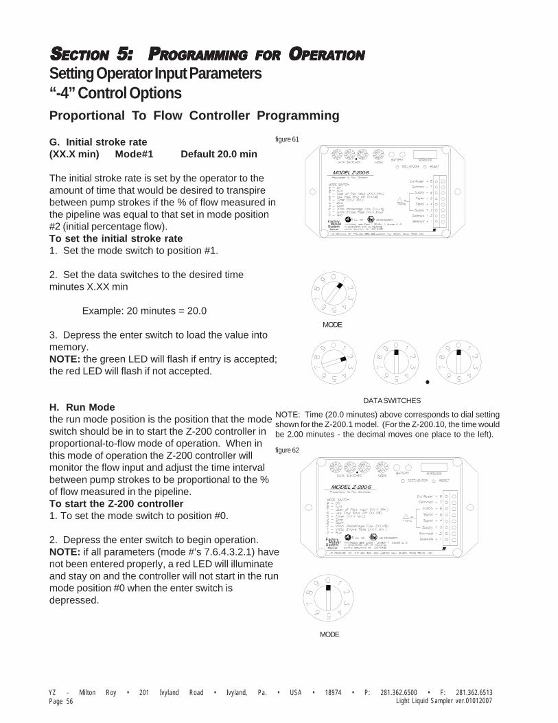
SSSSSECTIONECTIONECTIONECTIONECTION 5: 5: 5: 5: 5: P P P P PRRRRROGRAMMINGOGRAMMINGOGRAMMINGOGRAMMINGOGRAMMING FORFORFORFORFOR O O O O OPERAPERAPERAPERAPERATIONTIONTIONTIONTION
YZ - Milton Roy • 201 Ivyland Road • Ivyland, Pa. • USA • 18974 • P: 281.362.6500 • F: 281.362.6513Page 56 Light Liquid Sampler ver.01012007
Setting Operator Input Parameters“-4” Control OptionsProportional To Flow Controller Programming
G. Initial stroke rate(XX.X min) Mode#1 Default 20.0 min
The initial stroke rate is set by the operator to theamount of time that would be desired to transpirebetween pump strokes if the % of flow measured inthe pipeline was equal to that set in mode position#2 (initial percentage flow).To set the initial stroke rate1. Set the mode switch to position #1.
2. Set the data switches to the desired timeminutes X.XX min
Example: 20 minutes = 20.0
3. Depress the enter switch to load the value intomemory.NOTE: the green LED will flash if entry is accepted;the red LED will flash if not accepted.
H. Run Modethe run mode position is the position that the modeswitch should be in to start the Z-200 controller inproportional-to-flow mode of operation. When inthis mode of operation the Z-200 controller willmonitor the flow input and adjust the time intervalbetween pump strokes to be proportional to the %of flow measured in the pipeline.To start the Z-200 controller1. To set the mode switch to position #0.
2. Depress the enter switch to begin operation.NOTE: if all parameters (mode #’s 7.6.4.3.2.1) havenot been entered properly, a red LED will illuminateand stay on and the controller will not start in the runmode position #0 when the enter switch isdepressed.
NOTE: Time (20.0 minutes) above corresponds to dial settingshown for the Z-200.1 model. (For the Z-200.10, the time wouldbe 2.00 minutes - the decimal moves one place to the left).
MutualSystemApproved
Factory
MutualSystemApproved
Factory
MODE
DATA SWITCHES
MODE
figure 61
figure 62

SSSSSECTIONECTIONECTIONECTIONECTION 5: 5: 5: 5: 5: P P P P PRRRRROGRAMMINGOGRAMMINGOGRAMMINGOGRAMMINGOGRAMMING FORFORFORFORFOR O O O O OPERAPERAPERAPERAPERATIONTIONTIONTIONTION
Page 57YZ - Milton Roy • 201 Ivyland Road • Ivyland, Pa. • USA • 18974 • P: 281.362.6500 • F: 281.362.6513Light Liquid Sampler ver.01012007
Setting Operator Input Parameters“-4” Control Options
The Z-200 controller operates as a recycling timer.The time between solenoid actuations is set by theoperator and does not change in respect to pipelineflow conditions.
A. Calculate the sampling rate using the followinginformation:
B. Adjust the pump volume adjustment screw todesired displacement setting.
C. Set the mode switch to position #5.
D. Set the data switches to the desired time inMinutes XX.X minutes.
Example: 17.2 minutes - 17.2
D. Depress the enter switch to load the time intomemory to start operation.
Sampler Set-up - time-based Sampling
Example
1.5 Gallon Accumulator Vessel X 3785 cc/Gal. X 80% = 4542 cc/Sample Period
4542 cc/Sample Period = 2523 Pump Strokes/Sample Period 1.8cc/Pump Stroke
2523 Pump Strokes/Sample Period = 84 Strokes/Day 30 Days/Sample Period
1440 Min./Day = 17.14 Min/Stroke (Round Up to the next 1/10 Minute)....17.2 Minutes84 Strokes/Day
NOTE: Time (17.20 minutes) above corresponds to dial settingshown for the Z-200.1 model. (For the Z-200.10, the time wouldbe 1.72 minutes - the decimal moves one place to the left).
MutualSystemApproved
Factory
DATA SWITCHES
MODE
figure 63
figure 64
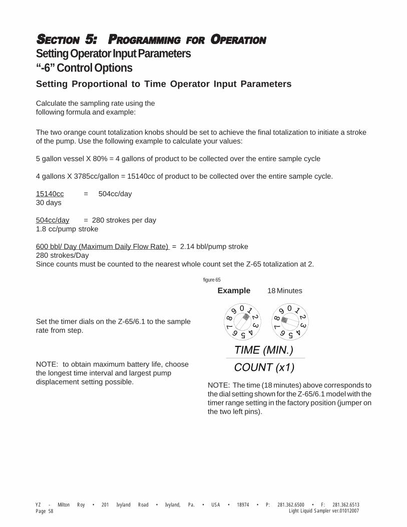
SSSSSECTIONECTIONECTIONECTIONECTION 5: 5: 5: 5: 5: P P P P PRRRRROGRAMMINGOGRAMMINGOGRAMMINGOGRAMMINGOGRAMMING FORFORFORFORFOR O O O O OPERAPERAPERAPERAPERATIONTIONTIONTIONTION
YZ - Milton Roy • 201 Ivyland Road • Ivyland, Pa. • USA • 18974 • P: 281.362.6500 • F: 281.362.6513Page 58 Light Liquid Sampler ver.01012007
Setting Operator Input Parameters“-6” Control Options
Calculate the sampling rate using thefollowing formula and example:
Set the timer dials on the Z-65/6.1 to the samplerate from step.
NOTE: to obtain maximum battery life, choosethe longest time interval and largest pumpdisplacement setting possible. NOTE: The time (18 minutes) above corresponds to
the dial setting shown for the Z-65/6.1 model with thetimer range setting in the factory position (jumper onthe two left pins).
Example
32
09
6
87
1
32
5 4
09 1
678
5 4
18 Minutes
Setting Proportional to Time Operator Input Parameters
The two orange count totalization knobs should be set to achieve the final totalization to initiate a strokeof the pump. Use the following example to calculate your values:
5 gallon vessel X 80% = 4 gallons of product to be collected over the entire sample cycle
4 gallons X 3785cc/gallon = 15140cc of product to be collected over the entire sample cycle.
15140cc = 504cc/day30 days
504cc/day = 280 strokes per day1.8 cc/pump stroke
600 bbl/ Day (Maximum Daily Flow Rate) = 2.14 bbl/pump stroke280 strokes/DaySince counts must be counted to the nearest whole count set the Z-65 totalization at 2.
figure 65
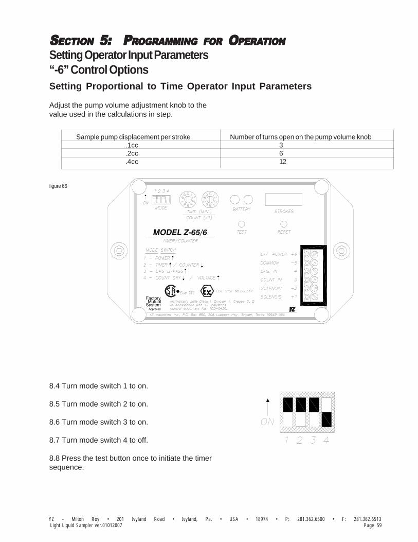
SSSSSECTIONECTIONECTIONECTIONECTION 5: 5: 5: 5: 5: P P P P PRRRRROGRAMMINGOGRAMMINGOGRAMMINGOGRAMMINGOGRAMMING FORFORFORFORFOR O O O O OPERAPERAPERAPERAPERATIONTIONTIONTIONTION
Page 59YZ - Milton Roy • 201 Ivyland Road • Ivyland, Pa. • USA • 18974 • P: 281.362.6500 • F: 281.362.6513Light Liquid Sampler ver.01012007
Setting Operator Input Parameters“-6” Control Options
8.4 Turn mode switch 1 to on.
8.5 Turn mode switch 2 to on.
8.6 Turn mode switch 3 to on.
8.7 Turn mode switch 4 to off.
8.8 Press the test button once to initiate the timersequence.
Adjust the pump volume adjustment knob to thevalue used in the calculations in step.
Number of turns open on the pump volume knob3612
Sample pump displacement per stroke.1cc.2cc.4cc
SystemMutual
Approved
Factory
Setting Proportional to Time Operator Input Parameters
figure 66

SSSSSECTIONECTIONECTIONECTIONECTION 5: 5: 5: 5: 5: P P P P PRRRRROGRAMMINGOGRAMMINGOGRAMMINGOGRAMMINGOGRAMMING FORFORFORFORFOR O O O O OPERAPERAPERAPERAPERATIONTIONTIONTIONTION
YZ - Milton Roy • 201 Ivyland Road • Ivyland, Pa. • USA • 18974 • P: 281.362.6500 • F: 281.362.6513Page 60 Light Liquid Sampler ver.01012007
Setting Operator Input Parameters“-6” Control Options
Z-65 Controller Set Up:The Mode Switch should be set as follows:#1 Power "On"
#2 Counter
#3 DPS Bypass
#4 Count Dry
The two orange count totalization knobs should be set to achieve the totalization to initiate a stroke of thepump. Use the following example to calculate your values:
5 gallon vessel X 80% = 4 gallons of product to be collected over the entire sample cycle
4 gallons X 3785cc/gallon = 15140cc of product to be collected over the entire sample cycle.
15140cc = 504cc/day30 days
504cc/day = 280 strokes per day1.8 cc/pump stroke
600 bbl/ Day (Maximum Daily Flow Rate) = 2.14 bbl/pump stroke280 strokes/DaySince counts must be counted to the nearest whole count set the Z-65 totalization at 2, assuming thepulses are sent at rate of 1 pulse per bbl..
Verify Power switch positions:Turn on the Z-65 power switch. (Z-65 mode S #1).
Setting Proportional to Flow Operator Input Parameters
NOTE: The count(2 counts) above corresponds tothe dial setting shown for the Z-65/6.1 model with thetimer range setting in the factory position (jumper onthe two left pins). See Section Timer Range Setting.
Example
32
09
6
87
1
32
5 4
09 1
678
5 4
2 Counts
figure 67

SSSSSECTIONECTIONECTIONECTIONECTION 5: 5: 5: 5: 5: P P P P PRRRRROGRAMMINGOGRAMMINGOGRAMMINGOGRAMMINGOGRAMMING FORFORFORFORFOR O O O O OPERAPERAPERAPERAPERATIONTIONTIONTIONTION
Page 61YZ - Milton Roy • 201 Ivyland Road • Ivyland, Pa. • USA • 18974 • P: 281.362.6500 • F: 281.362.6513Light Liquid Sampler ver.01012007
Setting Operator Input Parameters“-7” Control Options
:
80% of 5 gal. sample accumulator volume = 15,140 cc = 8,411 Pump Strokes per Sample CyclePump Displacement (0.25 to 1.8 cc/stroke) = 1.8
8,411 (Pump Strokes per Sample Cycle) = 280 Pump Strokes Per Day30 (# Days in the Sample Cycle)
32,000 (Average Flow Rate Per Day) = 3,200 (Average # of Pulses/Day) 10 (Measured Flow Volume per Pulse)
3,200 (Average # of Pulses/Day) = 11.4 Pulses per Stroke of the Pump (Counter Setting)280 Pump Strokes Per Day [Round up to 12 Pulses per Stroke of the Pump
(Counter Setting)]
figure 69
The heart of the electronic control package provided with your sampling system is a totalizing counter. Thetotalizer counts pulses from meter contacts or other flow monitoring devices. The sample pump is actuated aftera predetermined number of pulses have been counted.
The number of pulses required before taking a sample is easily programmed and changed in the totalizer. Thetotalizer can also sustain a loss of power without having to be reprogrammed.
All electronics are housed in explosion proof enclosures and are rated for use in Class I, Division 1, Groups Cand D hazardous locations.
Refer to figure 69 below for calculation example.
Setting Proportional to Flow Operator Input Parameters

SSSSSECTIONECTIONECTIONECTIONECTION 5: 5: 5: 5: 5: P P P P PRRRRROGRAMMINGOGRAMMINGOGRAMMINGOGRAMMINGOGRAMMING FORFORFORFORFOR O O O O OPERAPERAPERAPERAPERATIONTIONTIONTIONTION
YZ - Milton Roy • 201 Ivyland Road • Ivyland, Pa. • USA • 18974 • P: 281.362.6500 • F: 281.362.6513Page 62 Light Liquid Sampler ver.01012007
Notes

SSSSSECTIONECTIONECTIONECTIONECTION 6: 6: 6: 6: 6: M M M M MECHANICALECHANICALECHANICALECHANICALECHANICAL S S S S SYYYYYSTEMSTEMSTEMSTEMSTEM
Page 63YZ - Milton Roy • 201 Ivyland Road • Ivyland, Pa. • USA • 18974 • P: 281.362.6500 • F: 281.362.6513Light Liquid Sampler ver.01012007
PNR-2P Sample Pump & Balance Valve
The PNR-2P Sample Pump, refer to Apendix A,page 87, is a positive displacement plungerpump designed to be mounted directly on thepipeline. It has an adjustable displacement of0.25 to 1.8cc and achieves proportional-to-flowsampling through adjustment of the systemelectronic control discussed in Section 5.
As the plunger returns upward after completing astroke, the pump chamber fills with productthrough the inlet check valve. The inlet checkvalve is a dart type valve designed to seat on ano-ring. The inlet check valve is spring loaded toensure a positive seating action after everystroke. When the pump is actuated , the plungermoves downward, displacing product throughthe discharge check valve known as the balancevalve.
The Balance Valve, refer to Apendix A, page 91,automatically senses pipeline pressure andadjusts to ensure that product is not allowed tofree flow to the product vessel. When thepipeline pressure is greater than the prechargepressure on the accumulator vessel, the balancevalve dart is pushed up against the seat and thetop head of the balance valve. As the pumpstrokes, the pressure created in the pumpchamber forces the balance valve dart off theseat, allowing product to be pumped to theaccumulator vessel. Once the pump completesits stroke, the pressure across the balance valveequalizes and the dart is returned to a sealingposition by its spring.
In the event that the accumulator vesselprecharge pressure is greater than the pipelinepressure, the balance valve dart and seat arepushed apart by the product pressure in theaccumulator vessel. In this situation the checkvalve wafer located between the balance valveand the sample pump acts as a back check toprevent the escape of product previously cap-tured in the accumulator vessel. As the pumpstrokes, the pressure created in the pumpchamber forces the check valve wafer off theseat, allowing product to be pumped to theaccumulator vessel. Once the pump completesits stroke, the pressure across the check valveequalizes and the wafer is returned to a sealingposition by its spring.

SSSSSECTIONECTIONECTIONECTIONECTION 6: 6: 6: 6: 6: M M M M MECHANICALECHANICALECHANICALECHANICALECHANICAL S S S S SYYYYYSTEMSTEMSTEMSTEMSTEM
YZ - Milton Roy • 201 Ivyland Road • Ivyland, Pa. • USA • 18974 • P: 281.362.6500 • F: 281.362.6513Page 64 Light Liquid Sampler ver.01012007
LPR-2P Sample Pump & Balance Valve
The LPR-2 Sample Pump, refer to Appendix A,page 88, is a positive displacement plungerpump designed for slip stream attachment to thepipeline. It has an adjustable displacement of0.25 to 1.8cc and achieves proportional-to-flowsampling through adjustment of the systemelectronic control discussed in Section 5.
As the plunger returns upward after completing astroke, the pump chamber fills with productthrough the inlet check valve. The inlet checkvalve is a dart type valve designed to seat on ano-ring. The inlet check valve is spring loaded toensure a positive seating action after everystroke. When the pump is actuated , the plungermoves downward, displacing product through thedischarge check valve known as the balancevalve.
The Balance Valve, refer to Appendix A, page 91,automatically senses pipeline pressure andadjusts to ensure that product is not allowed tofree flow to the product vessel. When the pipe-line pressure is greater than the prechargepressure on the accumulator vessel, the balancevalve dart is pushed up against the seat and thetop head of the balance valve. As the pumpstrokes, the pressure created in the pumpchamber forces the balance valve dart off theseat, allowing product to be pumped to theaccumulator vessel. Once the pump completesits stroke, the pressure across the balance valveequalizes and the dart is returned to a sealingposition by its spring.
In the event that the accumulator vesselprecharge pressure is greater than the pipelinepressure, the balance valve dart and seat arepushed apart by the product pressure in theaccumulator vessel. In this situation the checkvalve wafer located between the balance valveand the sample pump acts as a back check toprevent the escape of product previously cap-tured in the accumulator vessel. As the pumpstrokes, the pressure created in the pumpchamber forces the check valve wafer off theseat, allowing product to be pumped to theaccumulator vessel. Once the pump completesits stroke, the pressure across the check valveequalizes and the wafer is returned to a sealingposition by its spring.

SSSSSECTIONECTIONECTIONECTIONECTION 6: 6: 6: 6: 6: M M M M MECHANICALECHANICALECHANICALECHANICALECHANICAL S S S S SYYYYYSTEMSTEMSTEMSTEMSTEM
Page 65YZ - Milton Roy • 201 Ivyland Road • Ivyland, Pa. • USA • 18974 • P: 281.362.6500 • F: 281.362.6513Light Liquid Sampler ver.01012007
PNR-2H Sample Pump & Balance Valve
The PNR-2H Sample Pump, refer to Appendix A,page 89, is a positive displacement plungerpump designed to be mounted directly on thepipeline. It has an adjustable displacement of0.25 to 1.8cc achieves proportional-to-flowsampling through adjustment of the systemelectronic control discussed in Section 5.
As the plunger returns upward after completing astroke, the pump chamber fills with productthrough the inlet check valve. The inlet checkvalve is a dart type valve designed to seat on ano-ring. The inlet check valve is spring loaded toensure a positive seating action after everystroke. When the pump is actuated , the plungermoves downward, displacing product through thedischarge check valve.
The Balance Valve, refer to Appendix A, page 91,automatically senses pipeline pressure andadjusts to ensure that product is not allowed tofree flow to the product vessel. When the pipe-line pressure is greater than the prechargepressure on the accumulator vessel, the balancevalve dart is pushed up against the seat and thetop head of the balance valve. As the pumpstrokes, the pressure created in the pumpchamber forces the balance valve dart off theseat, allowing product to be pumped to theaccumulator vessel. Once the pump completesits stroke, the pressure across the balance valveequalizes and the dart is returned to a sealingposition by its spring.
In the event that the accumulator vesselprecharge pressure is greater than the pipelinepressure, the balance valve dart and seat arepushed apart by the product pressure in theaccumulator vessel. In this situation the checkvalve wafer located between the balance valveand the sample pump acts as a back check toprevent the escape of product previously cap-tured in the accumulator vessel. As the pumpstrokes, the pressure created in the pumpchamber forces the check valve wafer off theseat, allowing product to be pumped to theaccumulator vessel. Once the pump completesits stroke, the pressure across the check valveequalizes and the wafer is returned to a sealingposition by its spring.

SSSSSECTIONECTIONECTIONECTIONECTION 6: 6: 6: 6: 6: M M M M MECHANICALECHANICALECHANICALECHANICALECHANICAL S S S S SYYYYYSTEMSTEMSTEMSTEMSTEM
YZ - Milton Roy • 201 Ivyland Road • Ivyland, Pa. • USA • 18974 • P: 281.362.6500 • F: 281.362.6513Page 66 Light Liquid Sampler ver.01012007
LPR-2H Sample Pump & Balance Valve
The LPR-2H Sample Pump, refer to Appendix A,page 90, is a positive displacement plungerpump designed for slip stream attachment to thepipeline. It has an adjustable displacement of0.25 to 1.8cc and achieves proportional-to-flowsampling through adjustment of the systemelectronic control discussed in Section 5.
As the plunger returns upward after completing astroke, the pump chamber fills with productthrough the inlet check valve. The inlet checkvalve is a dart type valve designed to seat on ano-ring. The inlet check valve is spring loaded toensure a positive seating action after everystroke. When the pump is actuated , the plungermoves downward, displacing product through thedischarge check valve known as the balancevalve.
The Balance Valve, refer to Appendix A, page 91,automatically senses pipeline pressure andadjusts to ensure that product is not allowed tofree flow to the product vessel. When the pipe-line pressure is greater than the prechargepressure on the accumulator vessel, the balancevalve dart is pushed up against the seat and thetop head of the balance valve. As the pumpstrokes, the pressure created in the pumpchamber forces the balance valve dart off theseat, allowing product to be pumped to theaccumulator vessel. Once the pump completesits stroke, the pressure across the balance valveequalizes and the dart is returned to a sealingposition by its spring.
In the event that the accumulator vesselprecharge pressure is greater than the pipelinepressure, the balance valve dart and seat arepushed apart by the product pressure in theaccumulator vessel. In this situation the checkvalve wafer located between the balance valveand the sample pump acts as a back check toprevent the escape of product previously cap-tured in the accumulator vessel. As the pumpstrokes, the pressure created in the pumpchamber forces the check valve wafer off theseat, allowing product to be pumped to theaccumulator vessel. Once the pump completesits stroke, the pressure across the check valveequalizes and the wafer is returned to a sealingposition by its spring.

SSSSSECTIONECTIONECTIONECTIONECTION 6: 6: 6: 6: 6: M M M M MECHANICALECHANICALECHANICALECHANICALECHANICAL S S S S SYYYYYSTEMSTEMSTEMSTEMSTEM
Page 67YZ - Milton Roy • 201 Ivyland Road • Ivyland, Pa. • USA • 18974 • P: 281.362.6500 • F: 281.362.6513Light Liquid Sampler ver.01012007
Accumulator VesselThe YZ Product Accumulator Vessel, refer toApendix A, page 94, is designed to maintain acomposite sample in the liquid phase. This isaccomplished by using a free-floating pistondesign and an inert precharge gas system, referto Apendix A, page 93. As product is collectedin the accumulator vessel, the precharge gassystem maintains a constant pressure on top ofthe vessel piston. If this pressure is at least 100to 150 psi above the vapor pressure of theproduct being sampled, the sampled product willbe prevented from flashing to the vapor phase.
Product enters the cylinder through the head inthe bottom of the cylinder. This head is theaccumulator vessel product head. Theprecharge gas is communicated to theaccumulator vessel through the precharge head,which is located on the top of the accumulatorcylinder.
The actuator assembly is located on the top ofthe accumulator cylinder and serves two func-tions. The first is to provide mixing of thesampled product by moving the mixing disc upand down within the product portion of theaccumulator cylinder. This is done by introduc-ing pressure to one side of the mixer pistonassembly and then by applying pressure to theopposite side of the mixer piston assembly.
The second function of the actuator assembly isto provide indication of the amount of productcollected within the vessel. This is shown locallyon the magnetic volume scale mounted on theactuator assembly cylinder.

SSSSSECTIONECTIONECTIONECTIONECTION 6: 6: 6: 6: 6: M M M M MECHANICALECHANICALECHANICALECHANICALECHANICAL S S S S SYYYYYSTEMSTEMSTEMSTEMSTEM
YZ - Milton Roy • 201 Ivyland Road • Ivyland, Pa. • USA • 18974 • P: 281.362.6500 • F: 281.362.6513Page 68 Light Liquid Sampler ver.01012007
5-Way Cross
The Five-way Cross Assembly, refer to ApendixA, page 92, is located on the front of the skidand includes the following items: product inlettubing fitting, pressure gauge, relief valve, robvalve, accumulator vessel isolation valve/dis-charge tubing fitting, and the five-way cross.
The pressure gauge is used during normaloperation to indicate the pressure within theaccumulator vessel. During start-up andtroubleshooting procedures it is used in conjunc-tion with the accumulator vessel isolation valveto check pump performance.
The YZ relief valve is a reseating type valvewhich is factory set to relieve at 1800 psi. Alsoincorporated into the relief valve design is apositive indication feature which indicates that ithas relieved. If the system reaches a pressuregreater than the relief valve setting, the resultingrelease of product pushes the black relief valveindicator outside the relief valve body. Thisinforms the system operator during his nextsystem check that an over pressure conditionhas occurred. The indicator is reset by pushingit back into the relief valve body.
The rob valve is a YZ needle valve which is usedto remove product from the accumulator vesselat the end of the sample period. This valve isnormally closed.
The accumulator vessel isolation valve is usedto isolate the accumulator vessel from the rest ofthe product carrying portion of the samplingsystem. This valve is normally open.

SSSSSECTIONECTIONECTIONECTIONECTION 6: 6: 6: 6: 6: M M M M MECHANICALECHANICALECHANICALECHANICALECHANICAL S S S S SYYYYYSTEMSTEMSTEMSTEMSTEM
Page 69YZ - Milton Roy • 201 Ivyland Road • Ivyland, Pa. • USA • 18974 • P: 281.362.6500 • F: 281.362.6513Light Liquid Sampler ver.01012007
Actuation/Mixing System (Pneumatic)
The function of the 80 psi instrument air supplyis to provide an actuation power source for thesample pump and the accumulator vessel mixingsystem, refer to Apendix A, page 96. Con-structed as an integral component of the entiresampling system, the entire system is pressuretested at the factory prior to shipment.
The instrument air source is internally connectedto individual components within the samplersystem. These split the pneumatic sourcebetween sample pump actuation and accumula-tor vessel mixing. The "actuation" leg is piped toa pressure regulator (factory set at 38 psi) andon to a three-way proof solenoid valve. Thissolenoid valve is normally closed and is mountedin the sample system enclosure. It is openedwhen energized by the sampler electroniccontrol package. Opening the solenoid valveallows pneumatic pressure to actuate the samplepump. The actuation tubing to the SamplePump from the solenoid connection must be fieldinstalled by the customer.
The "mixing" leg of the system is tubed directlyto the inlet of the accumulator mixing valve. Theinlet is located on the right side of the switch.The mixing switch is a three position switch, withthe center position being the off position. Whenthe mixing switch is moved to the up position,the mixing disc is moved up in the productaccumulator. Moving the mixing switch to thedown position causes the product accumulatormixing disc to move down in the product accu-mulator. The sample in the accumulator vesselis mixed by moving the mixing handle alternatelyup and then down. Four or fives passes throughthe sample should provide sufficient mixing.

SSSSSECTIONECTIONECTIONECTIONECTION 6: 6: 6: 6: 6: M M M M MECHANICALECHANICALECHANICALECHANICALECHANICAL S S S S SYYYYYSTEMSTEMSTEMSTEMSTEM
YZ - Milton Roy • 201 Ivyland Road • Ivyland, Pa. • USA • 18974 • P: 281.362.6500 • F: 281.362.6513Page 70 Light Liquid Sampler ver.01012007
Actuation/Mixing System (Hydraulic)
The function of the hydraulic power pack is toprovide a hydraulic actuation power source to thesample pump and the power mixing system onthe product accumulator vessel, refer to Appen-dix A, page 99. The power pack is a unitizedsystem that consists of a pump, motor, and four(4) quart reservoir. Mounted directly on thesample skid, the power pack is factory wired tothe Mix/Mode switch, and the Counter. It is readyfor wiring to the power supply and control func-tion device (customer supplied). The HydraulicPower Pack has been factory tested as anintegral component of the entire samplingsystem, the power pack is filled with hydraulicfluid at the factory prior to shipment; however,after you install the sampler skid check the fluidlevel, and add additional fluid if required.
The oil level should be about 3/4" below the ventfitting on the oil reservoir. The system wasoriginally filled with Phillips MAGNUS "A"KV 5W-20 oil. This oil or equivalent should be used. Ifanother type oil is desired, the entire systemshould be drained. Acceptable oils are cleanhydraulic oil with a viscosity range of 150-300SSU at 100° F. Recommended operating tem-peratures are 10° F to 165° F.
The power pack operates in one of two modes -the Sample mode or the Mix mode. In theSample mode, the power pack actuates thesample pump when the electrical control device(customer supplied) determines it is time to takea sample. In the Mix mode, the power pack isused to move the mixing disc in the productaccumulator vessel.
Control of the power pack is accomplished usinga hydraulic fluid diverter valve, two electricalswitches, and the Counter. The diverter valve ismounted on the discharge side of the powerpack pump and has two positions-Sample andMix. The electrical switches are located abovethe Hydraulic Power Pack. The switch on theright side is the mode switch and has two posi-tions - "Sample" and "Mix". The switch on theleft side is the Test/Mixing Switch and has threepositions. The function of this three positionswitch is dependent upon the position of themode switch and the diverter valve.

SSSSSECTIONECTIONECTIONECTIONECTION 7: 7: 7: 7: 7: S S S S SYYYYYSTEMSTEMSTEMSTEMSTEM O O O O OPERAPERAPERAPERAPERATIONTIONTIONTIONTION
Page 71YZ - Milton Roy • 201 Ivyland Road • Ivyland, Pa. • USA • 18974 • P: 281.362.6500 • F: 281.362.6513Light Liquid Sampler ver.01012007
Preparing The System for Operation
Sample Pump PrimingBefore the pump begins normal operation afterinitial installation or maintenance, the samplepump must be purged of all air in the samplechamber. The purge valve on the SamplePump/Balance Valve, refer to Apendix A, pages 87-90,is used to evacuate the air from the chamberand to make sure the pump is liquid-packed. Ifthe pump is not purged before being placed intooperation, it will not function properly.
To purge the pump, open the purge valve lo-cated on the side of the Sample Pump/BalanceValve assembly. The product supply valve canthen be opened to allow pipeline product to purgethe air within the pump. Once product beginsexiting the purge valve, close the purge valve.The sample pump is now ready to begin opera-tion.
Product Line TestClose the isolation valve located on the bottomof the Five-way Cross Assembly, refer toApendix A, page 92. Stroke the sample pumpuntil the system pressure reaches 1800 psi onthe Five-Way Cross Assembly Gauge. Thepressure should hold steady between pumpstrokes. Once the system is at 1800 psi, leaktest all connections. Once the system has beentested, open the isolation valve located on thebottom of the Five-Way Cross Assembly.
Sample Vessel ConnectionConnect a constant pressure portable samplevessel (DuraSite) to the rob valve located on theFive-way Cross Assembly, refer to Apendix A,page 92 using a short section of 1/8" or 1/4"stainless steel tubing. The portable samplevessel must also be precharged to 100-150 psiabove the vapor pressure of the product, refer topage 72. Open the rob valve allow product intothe DuraSite as the pump takes samples. Closethe rob valve and remove the sample vesselfrom the rob valve, at the end of each samplecycle, and replace it with a clean empty vesselfor the next cycle.
SSSSSECTIONECTIONECTIONECTIONECTION 7: 7: 7: 7: 7: S S S S SYYYYYSTEMSTEMSTEMSTEMSTEM O O O O OPERAPERAPERAPERAPERATIONTIONTIONTIONTION
YZ - Milton Roy • 201 Ivyland Road • Ivyland, Pa. • USA • 18974 • P: 281.362.6500 • F: 281.362.6513Page 72 Light Liquid Sampler ver.01012007
DuraSite Sample Vessel ConnectionPurpose: The DuraSite Portable Sample Vesselpermits the user to remove a liquid or gas hydro-carbon sample from a pipeline or a sampling de-vice. This is accomplished without changing thepressure of the product or exposing it to acontaminant fluid. If properly used and maintainedthe DuraSite will provide many years of safe, ac-curate and clean sampling.
Use: The DuraSite is a very safe device to use.As with any equipment dealing with flammableproducts, it is mandatory that a good, thoroughoperator training procedure be established priorto use.
Typical use of the cylinder would be as follows:
Step 1: (In The Lab) Connect a regulated inertgas supply to the pre-charge valve. The productvalve should be open. By carefully controlling thepre-charge valve and the regulator, the cylindercan be slowly charged with pre-charge gas(NOTE: This should be done slowly to preventslamming the piston down to the opposite end).The pressure on the pre-charge pressure gaugeshould be brought to a reading of 10-50 psi abovethe expected pressure of the product in the field .Close the pre-charge valve and disconnect thegas supply. Check the pre-charge valve, reliefdevice, and the pre-charge pressure gauge forleaks. Any leaks should be stopped before con-tinuing. The vessel should be placed in a paddedcarrying case and made ready for field use.
STEP 2: FOR COLLECTION OF SAMPLE FROMCOMPOSITE ACCUMULATOR VESSEL.
2a: Connect the product end of the pre-chargedsample vessel to the product supply. (Samplerproduct removal valve)NOTE: the pre-charge pressure gauge read-ing should be greater than the product supplypressure reading. If not, repeat Step 1 above.
2b: Once the vessel is connected to the productsupply, it is necessary to vent a small amount ofproduct prior to filling the vessel. This assuresfresh product and removes any air or gas whendealing with liquids. This can be done by loosen-ing the product purge valve a very small amountuntil the product is purged. After thorough purg-ing, the product purge valve should be tightened.
2c: The product pressure gauge reading shouldbe 10-50 psi below the pre-charge pressure gaugereading. By carefully opening the pre-chargevalve, the pressure becomes equalized, then be-gins to drop below the product pressure. The pre-charge valve should be carefully controlled so asto not vent the pre-charge gas too fast.
2d: When the cylinder becomes a maximum of80% full (see volume indicator), all valves shouldbe closed. The product connection is slowly bro-ken in order to vent any trapped product. Aftervessel removal, all connections should be checkedfor leaks and the pre-charge and product valveports capped to prevent leakage.
2e: Pack the DuraSite in appropriate carrying caseto meet D.O.T. guideline, with D.O.T. paperworkand transport to lab for analysis.
Step 3: (In The Lab) Prior to analysis, the prod-uct should be mixed. This is accomplished simplyand efficiently by inverting the cylinder end-over-end, causing the mixing ball to fall through theproduct. Approximately 10-12 trips of the mixingball through the product assures a homogenoussolution.
Step 4: The regulated pre-charge gas should bereconnected to the pre-charge side of the cylin-der. The pre-charge gas supply should remainopen during analysis.
Step 5: Purging a small amount of product fromthe vessel removes unmixed product from the tee,relief device, gauge, etc. The unit can now beconnected to a chromatograph and the productanalyzed.
Step 6: After analyzing, the remainder of the prod-uct should be dumped and the vessel properlycleaned. Normal cleaning can be accomplishedby rinsing the product end with a petroleum sol-vent and flushing with acetone. If a more thor-ough cleaning is required, the vessel should bedisassembled.
WARNING: A portable sample vessel shouldnever be filled to more than 80%. This allowsa 20% pre-charge cushion to absorb thermalexpansion of the product.
Shipping: Extreme care should be taken when pre-paring a vessel for shipment. Both valves shouldbe capped to prevent possible leakage. The ves-sel should be placed in a snug-fitting, well-paddedand durable case. All applicable DOT regulationsshould be adhered to.

SSSSSECTIONECTIONECTIONECTIONECTION 7: 7: 7: 7: 7: S S S S SYYYYYSTEMSTEMSTEMSTEMSTEM O O O O OPERAPERAPERAPERAPERATIONTIONTIONTIONTION
Page 73YZ - Milton Roy • 201 Ivyland Road • Ivyland, Pa. • USA • 18974 • P: 281.362.6500 • F: 281.362.6513Light Liquid Sampler ver.01012007
Seat Retaining Washer
P/N A6-0023
P/N A3-0347
Pre-Charge HeadYZ UniValve
P/N C6-1001
P/N A3-0156Rupture Disc
P/N C6-1500 (DS-800)
Rupture Disc Nut
P/N C6-1201 (DS-150)
P/N C6-1601 (DS-1000)P/N C6-1501 (DS-800)P/N C6-1401 (DS-500)P/N C6-1301 (DS-300)
P/N C6-1600 (DS-1000)
Tie Rod
P/N C6-1400 (DS-500)P/N C6-1300 (DS-300)P/N C6-1200 (DS-150)
P/N C3-0901
Cylinder
O-RingP/N A5-1021
Snap Ring
Valve SeatP/N A3-0063
P/N A3-0062
P/N C6-1005Mixing Ball
Piston Seal
O-RingP/N A5-1222
Stainless Steel
Back-Up WasherP/N A5-4222B
Hex NutsP/N C0-0048
P/N C6-1000Product HeadYZ UniValve
Purge Valve NutP/N A3-0080
P/N A3-0063Valve Seat
P/N C6-1003 (Ser. #4608+)
P/N 12-1006 (Ser. #0321 and Prior)P/N 12-1007 (Ser. #0322 - #0613)P/N 12-1008 (Ser. #0614 - #4087)P/N C6-1002 (Ser. #4088+)
Piston WasherP/N C6-1004
Piston
P/N 12-1018 (Ser. #0613 and Prior)P/N 12-1019 (Ser. #0614 - #4607)
Magnetic Volume Indicator
Gauge
P/N C6-1603 (DS-1000)P/N C6-1503 (DS-800)P/N C6-1403 (DS-500)P/N C6-1303 (DS-300)P/N C6-1203 (DS-150)
P/N A8-0036
Magnet Assembly
O-Ring Bonnet AssemblyP/N A3-0095
Knob (Black)P/N A3-0251
Set ScrewC0-0099
figure 70

SSSSSECTIONECTIONECTIONECTIONECTION 7: 7: 7: 7: 7: S S S S SYYYYYSTEMSTEMSTEMSTEMSTEM O O O O OPERAPERAPERAPERAPERATIONTIONTIONTIONTION
YZ - Milton Roy • 201 Ivyland Road • Ivyland, Pa. • USA • 18974 • P: 281.362.6500 • F: 281.362.6513Page 74 Light Liquid Sampler ver.01012007
Notes
SSSSSECTIONECTIONECTIONECTIONECTION 8: 8: 8: 8: 8: S S S S SYYYYYSTEMSTEMSTEMSTEMSTEM M M M M MAINTENAINTENAINTENAINTENAINTENANCEANCEANCEANCEANCE
Page 75YZ - Milton Roy • 201 Ivyland Road • Ivyland, Pa. • USA • 18974 • P: 281.362.6500 • F: 281.362.6513Light Liquid Sampler ver.01012007
Preventative MaintenanceSchedule
A preventative maintenance program serves to antici-pate maintenance issues prior to waiting until the systemrequires service. Like changing the oil & filters in anautomobile, by choosing to service the various parts andoperation in the Sampling System at regular intervals,the technician can perform the maintenance servicewhen desired, rather than when required, such as in themiddle of night.
The key is to perform maintenance before it is required.The preventative maintenance schedule implementedshould consider the application of the sampler. Many ofthese considerations include: the weather environment;the condition of, the actuation gas, the product conditionand quality, and the pump stroke frequency. All of theseissues must be considered when establishing a preven-tative maintenance schedule.
Recommended Maintenance ScheduleMonthly Inspection
1. Verify system pressures2. Check for leaks
Annual Inspection1. Rebuild pump2. Clean and service the pneumatic mixing valve if
so equipped4. Test the relief valve and service, as needed5. Test regulators and service, as needed6. Test the Light Liquid Sampler System perfor-
mance
Bi-Annual Inspection1. Perform the annual inspection listed above2. Replace solenoid if so equipped3. Rebuild Accumulator Vessel
Recommended Spare Parts List
Part # Description RecommendedQuantity
D3-0152 PNR-2P/LPR-2P pump sealreplacement kit 1
OR
D3-0153 PNR-2H/LPR-2H pump sealreplacement kit 1
D3-0139 Balance Valve Repair Kit 1

SSSSSECTIONECTIONECTIONECTIONECTION 8: 8: 8: 8: 8: S S S S SYYYYYSTEMSTEMSTEMSTEMSTEM M M M M MAINTENAINTENAINTENAINTENAINTENANCEANCEANCEANCEANCE
YZ - Milton Roy • 201 Ivyland Road • Ivyland, Pa. • USA • 18974 • P: 281.362.6500 • F: 281.362.6513Page 76 Light Liquid Sampler ver.01012007
Notes

SSSSSECTIONECTIONECTIONECTIONECTION 9: 9: 9: 9: 9: S S S S SYYYYYSTEMSTEMSTEMSTEMSTEM TTTTTRRRRROUBLESHOOOUBLESHOOOUBLESHOOOUBLESHOOOUBLESHOOTINGTINGTINGTINGTING
Page 77YZ - Milton Roy • 201 Ivyland Road • Ivyland, Pa. • USA • 18974 • P: 281.362.6500 • F: 281.362.6513Light Liquid Sampler ver.01012007
How to Use This Section
The recommendations contained in this section should beused as a preliminary information resource to remedy opera-tional issues with the PNR-2P Sampling System. It isimportant to read all of the definitions and notes prior to initiatingwork.
Each subsection contains a description of the indicatorsfollowed by a step-by-step trouble shooting procedure.
For Additional Help
Any issue that can not be resolved through the use ofthis reference, please contact YZ Technical Service at:
T: 1.800.653.9435T: 1.281.362.6500, International CallsF: 1.281.362.6513Em: [email protected]
SAFETY NOSAFETY NOSAFETY NOSAFETY NOSAFETY NOTESTESTESTESTES• Always use extreme care when performing mainte-
nance on Sampling Systems. Always take necessarymeasures to assure that electrical classification in thearea is considered, before, and during all repairs, andthat necessary steps are taken to maintain properelectrical procedures for the classification of the area.
• Take special care when disconnecting any fitting, toassure that product and/or pressure will not bereleased when the connection is broken. This systemmay contain liquid and/or gas at high pressures.
Step-by-Step Resolution
Using a step-by-step method to resolve issues on theSampling System will reduce maintenance time andassist in returning the system to service quicker.
The following represent the recommended chronology toresolve issues:
Resolve issues to the following order:a. Actuation Gas Pressure, page 77b. Electrical Power, page 78c. Sample Pulse, page 79d. Pump Performance, page 79e. Pre-Charge Pressure /Product Accumulator
Vessel , page 80
Actuation Gas Pressure
This section should be used to troubleshoot samplerperformance, when the Sample Pump will not actuate,and/or when the pneumatic power mixing system on theAccumulator Vessel will not function.
Actuation Gas Troubleshooting Steps
1. Verify the supply gas valves, and regulators supply-ing gas to the sampler system are properly function-ing, and adjusted.
2. Disconnect the Pneumatic Supply connection at thetop of the Sample Pump.
a. There should NOT be any gas pressurepresent. Gas pressure should be present forONLY 3 seconds each time a sample pulse isreceived by the sample systems from the flowmonitoring device, that signals the samplerwhen to take a sample.
b. Initiate a sample with the flow monitoring devicepulse, and observe to see if a 3 second burst ofgas is expelled from the connection loosened instep 2 above.
- PNEUMA- PNEUMA- PNEUMA- PNEUMA- PNEUMATIC SYTIC SYTIC SYTIC SYTIC SYSTEMSSTEMSSTEMSSTEMSSTEMS

SSSSSECTIONECTIONECTIONECTIONECTION 9: 9: 9: 9: 9: S S S S SYYYYYSTEMSTEMSTEMSTEMSTEM TTTTTRRRRROUBLESHOOOUBLESHOOOUBLESHOOOUBLESHOOOUBLESHOOTINGTINGTINGTINGTING
YZ - Milton Roy • 201 Ivyland Road • Ivyland, Pa. • USA • 18974 • P: 281.362.6500 • F: 281.362.6513Page 78 Light Liquid Sampler ver.01012007
c. If a 3 second burst of gas is expelled fromthe connection loosened in step 2, theactuation system to the pump is functioningproperly. Reconnect the Pneumatic Supplyconnection to the top of the Sample Pump.Proceed to pump performance trouble-shooting, if the problem seems to be withyour pump, or proceed to step 3, if you arehaving difficulties with the power mixing ofyour sample system.
3. Disconnect the tubing at the top of the ActuatorHead of the Product Accumulator vessel. Thereshould not be any pressure there until the MixingValve is placed in the down mixing position.
a. If gas is flowing continually when this line isdisconnected, the Mixing Valve should berepaired, or replaced.
b. If gas does not flow to the loosened connectionwhen the Mixing Valve is actuated to the downposition, try moving the valve to the up position,and see if you get gas flow at the loosenedconnection. If you still have no gas flow to theloosened connection, the Mixing Valve shouldbe repaired, or replaced.
c. If gas does flow properly, to the loosenedconnection, when the Mixing Valve is placed inthe down mixing position, check the vent/muffleron the Mixing Valve to see if it may be stoppedup. Clean or replace the vent/muffler as required.
Electrical Power
IMPORIMPORIMPORIMPORIMPORTTTTTANT NOANT NOANT NOANT NOANT NOTE:TE:TE:TE:TE:All electronics are housed in explosion proofenclosures and are rated for use in Class I,Division 1, Groups C and D hazardous locations.
The power supply to the sampler must be properlyconnected and supplying power to the samplesystem, before it can be expected to perform. Oftenelectrical storms, or other electrical surges thatoccur at the sampler site may cause interruption ofthe power supply to the sampler. The power is usedto drive the solenoid for a duration of 3 secondseach time a sample is called for by the flow monitor-ing device connected to the sampler system.Electrical power troubleshooting will include steps toassure the power is actually getting to the solenoidfor the required duration, and that the solenoid isactivating the sample pump. The typical symptom tolead a technician to this step would be that thesample pump is not being actuated when a pulsefrom the flow monitoring device sends a dry contactsample pulse to the sampler.
Electrical Power Troubleshooting Steps
CACACACACAUTION:UTION:UTION:UTION:UTION:Prior to opening the electrical enclosure be sure todisconnect all power and pulse connections at thesafe end of wiring or perform test to assure the areaof the enclosure is safe to open the enclosure.
1. Verify the power is actually reaching the counter inthe Sample System electrical enclosure. Test forcontinuous power at the counter by connectingyour Voltmeter to the counter terminal pins, referSystem Control and Electronics in Section 4.
- PNEUMA- PNEUMA- PNEUMA- PNEUMA- PNEUMATIC SYTIC SYTIC SYTIC SYTIC SYSTEMSSTEMSSTEMSSTEMSSTEMS
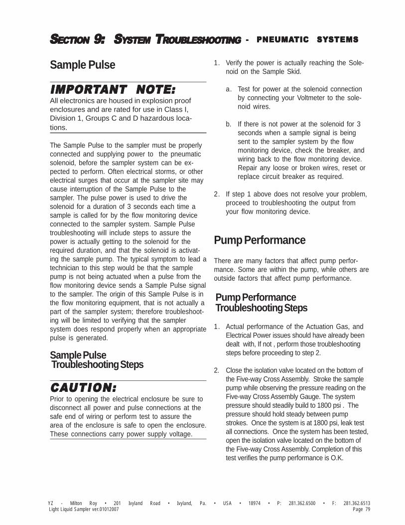
SSSSSECTIONECTIONECTIONECTIONECTION 9: 9: 9: 9: 9: S S S S SYYYYYSTEMSTEMSTEMSTEMSTEM TTTTTRRRRROUBLESHOOOUBLESHOOOUBLESHOOOUBLESHOOOUBLESHOOTINGTINGTINGTINGTING
Page 79YZ - Milton Roy • 201 Ivyland Road • Ivyland, Pa. • USA • 18974 • P: 281.362.6500 • F: 281.362.6513Light Liquid Sampler ver.01012007
Sample Pulse
IMPORIMPORIMPORIMPORIMPORTTTTTANT NOANT NOANT NOANT NOANT NOTE:TE:TE:TE:TE:All electronics are housed in explosion proofenclosures and are rated for use in Class I,Division 1, Groups C and D hazardous loca-tions.
The Sample Pulse to the sampler must be properlyconnected and supplying power to the pneumaticsolenoid, before the sampler system can be ex-pected to perform. Often electrical storms, or otherelectrical surges that occur at the sampler site maycause interruption of the Sample Pulse to thesampler. The pulse power is used to drive thesolenoid for a duration of 3 seconds each time asample is called for by the flow monitoring deviceconnected to the sampler system. Sample Pulsetroubleshooting will include steps to assure thepower is actually getting to the solenoid for therequired duration, and that the solenoid is activat-ing the sample pump. The typical symptom to lead atechnician to this step would be that the samplepump is not being actuated when a pulse from theflow monitoring device sends a Sample Pulse signalto the sampler. The origin of this Sample Pulse is inthe flow monitoring equipment, that is not actually apart of the sampler system; therefore troubleshoot-ing will be limited to verifying that the samplersystem does respond properly when an appropriatepulse is generated.
Sample Pulse Troubleshooting Steps
CACACACACAUTION:UTION:UTION:UTION:UTION:Prior to opening the electrical enclosure be sure todisconnect all power and pulse connections at thesafe end of wiring or perform test to assure thearea of the enclosure is safe to open the enclosure.These connections carry power supply voltage.
1. Verify the power is actually reaching the Sole-noid on the Sample Skid.
a. Test for power at the solenoid connectionby connecting your Voltmeter to the sole-noid wires.
b. If there is not power at the solenoid for 3seconds when a sample signal is beingsent to the sampler system by the flowmonitoring device, check the breaker, andwiring back to the flow monitoring device.Repair any loose or broken wires, reset orreplace circuit breaker as required.
2. If step 1 above does not resolve your problem,proceed to troubleshooting the output fromyour flow monitoring device.
Pump Performance
There are many factors that affect pump perfor-mance. Some are within the pump, while others areoutside factors that affect pump performance.
Pump Performance Troubleshooting Steps
1. Actual performance of the Actuation Gas, andElectrical Power issues should have already beendealt with, If not , perform those troubleshootingsteps before proceeding to step 2.
2. Close the isolation valve located on the bottom ofthe Five-way Cross Assembly. Stroke the samplepump while observing the pressure reading on theFive-way Cross Assembly Gauge. The systempressure should steadily build to 1800 psi . Thepressure should hold steady between pumpstrokes. Once the system is at 1800 psi, leak testall connections. Once the system has been tested,open the isolation valve located on the bottom ofthe Five-way Cross Assembly. Completion of thistest verifies the pump performance is O.K.
- PNEUMA- PNEUMA- PNEUMA- PNEUMA- PNEUMATIC SYTIC SYTIC SYTIC SYTIC SYSTEMSSTEMSSTEMSSTEMSSTEMS
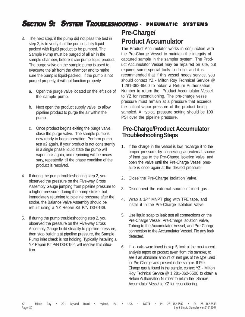
SSSSSECTIONECTIONECTIONECTIONECTION 9: 9: 9: 9: 9: S S S S SYYYYYSTEMSTEMSTEMSTEMSTEM TTTTTRRRRROUBLESHOOOUBLESHOOOUBLESHOOOUBLESHOOOUBLESHOOTINGTINGTINGTINGTING
YZ - Milton Roy • 201 Ivyland Road • Ivyland, Pa. • USA • 18974 • P: 281.362.6500 • F: 281.362.6513Page 80 Light Liquid Sampler ver.01012007
3. The next step, if the pump did not pass the test instep 2, is to verify that the pump is fully liquidpacked with liquid product to be pumped. TheSample Pump must be purged of all air in thesample chamber, before it can pump liquid product.The purge valve on the sample pump is used toevacuate the air from the chamber and to makesure the pump is liquid-packed. If the pump is notpurged properly, it will not function properly.
a. Open the purge valve located on the left side ofthe sample pump.
b. Next open the product supply valve to allowpipeline product to purge the air within thepump.
c. Once product begins exiting the purge valve,close the purge valve. The sample pump isnow ready to begin operation. Perform pumptest #2 again. If your product is not consistentlyin a single phase liquid state the pump willvapor lock again, and repriming will be neces-sary, repeatedly, till the phase condition of theproduct is resolved.
4. If during the pump troubleshooting step 2, youobserved the pressure on the Five-way CrossAssembly Gauge jumping from pipeline pressure toa higher pressure, during the pump stroke, butimmediately returning to pipeline pressure after thestroke, the Balance Valve Assembly should berebuilt using a YZ Repair Kit P/N D3-0139.
5. If during the pump troubleshooting step 2, youobserved the pressure on the Five-way CrossAssembly Gauge build steadily to pipeline pressure,then stop building at pipeline pressure, the SamplePump inlet check is not holding. Typically installing aYZ Repair Kit P/N D3-0152, will resolve this situa-tion.
Pre-Charge/Product AccumulatorThe Product Accumulator works in conjunction withthe Pre-Charge Vessel to maintain the integrity ofcaptured sample in the sampler system. The Prod-uct Accumulator Vessel may be repaired on site, butrequires some special tools to do so, and it isrecommended that if this vessel needs service, youshould contact YZ - Milton Roy Technical Service @1.281-362-6500 to obtain a Return AuthorizationNumber to return the Product Accumulator Vesselto YZ for reconditioning. The pre-charge vesselpressure must remain at a pressure that exceedsthe critical vapor pressure of the product beingsampled. A typical pressure setting should be 100PSI over the pipeline pressure.
Pre-Charge/Product Accumulator Troubleshooting Steps
1. If the charge in the vessel is low, recharge it to theproper pressure, by connecting an external sourceof inert gas to the Pre-Charge Isolation Valve, andopen the valve until the Pre-Charge Vessel pres-sure is once again at the desired pressure.
2. Close the Pre-Charge Isolation Valve.
3. Disconnect the external source of inert gas.
4. Wrap a 1/4” MNPT plug with TFE tape, andinstall it in the Pre-Charge Isolation Valve.
5. Use liquid soap to leak test all connections on thePre-Charge Vessel, Pre-Charge Isolation Valve,Tubing to the Accumulator Vessel, and Pre-Chargeconnection to the Accumulator Vessel. Fix any leakdetected.
6. If no leaks were found in step 5, look at the most recentanalysis report on product taken from this sampler, tosee if an abnormal amount of inert gas of the type usedfor Pre-Charge was present in the sample. If Pre-Charge gas is found in the sample, contact YZ - MiltonRoy Technical Service @ 1.281-362-6500 to obtain aReturn Authorization Number to return the SampleAccumulator Vessel to YZ for reconditioning.
- PNEUMA- PNEUMA- PNEUMA- PNEUMA- PNEUMATIC SYTIC SYTIC SYTIC SYTIC SYSTEMSSTEMSSTEMSSTEMSSTEMS

SSSSSECTIONECTIONECTIONECTIONECTION 9: 9: 9: 9: 9: S S S S SYYYYYSTEMSTEMSTEMSTEMSTEM TTTTTRRRRROUBLESHOOOUBLESHOOOUBLESHOOOUBLESHOOOUBLESHOOTINGTINGTINGTINGTING
Page 81YZ - Milton Roy • 201 Ivyland Road • Ivyland, Pa. • USA • 18974 • P: 281.362.6500 • F: 281.362.6513Light Liquid Sampler ver.01012007
How to Use This Section
The recommendations contained in this section shouldbe used as a preliminary information resource to remedyoperational issues with the LPR-2H Sampling System. Itis important to read all of the definitions and notes prior toinitiating work.
Each subsection contains a description of theindicators followed by a step-by-step trouble shoot-ing procedure.
For Additional Help
Any issue that can not be resolved through the useof this reference, please contact YZ TechnicalService at:
T: 1.800.653.9435T: 1.281.362.6500, International CallsF: 1.281.362.6513Em: [email protected]
SAFETY NOSAFETY NOSAFETY NOSAFETY NOSAFETY NOTESTESTESTESTES• Always use extreme care when performing mainte-
nance on Sampling Systems. Always takenecessary measures to assure that electricalclassification in the area is considered, before,and during all repairs, and that necessary stepsare taken to maintain proper electrical proceduresfor the classification of the area.
• Take special care when disconnecting any fitting,to assure that product and/or pressure will not bereleased when the connection is broken. Thissystem may contain liquid and/or gas at highpressures.
Step-by-Step Resolution
Using a step-by-step method to resolve issues onthe Sampling System will reduce maintenance timeand assist in returning the system to service quicker.
The following represent the recommended chronol-ogy to resolve issues:
Resolve issues to the following order:a. Electrical Power, page 81b. Hydraulic Power, page 83
Electrical Power
CACACACACAUTION:UTION:UTION:UTION:UTION:Prior to opening the electrical enclosure be sure todisconnect all power and pulse connections at thesafe end of wiring or perform test to assure the areaof the enclosure is safe to open the enclosure.
The 120 VAC power supply to the sampler must beproperly connected and supplying power (120 VAC@ 20 amps) to the sample system, before it can beexpected to perform. Often electrical storms, orother electrical surges that occur at the sampler sitemay cause interruption of the power supply to thesampler. The power is used to drive the HydraulicPower Pack for a minimum duration of 3 secondseach time a sample is called for by the counterwhen the programmed number of pulses has beencounted as provided by a flow monitoring deviceconnected to the sampler system, and to run thepower pack longer during the sample mixing modeof operation. Electrical power troubleshooting willinclude steps to assure the 120 VAC power isactually getting to the Power Pack for the requiredduration. The typical symptom to lead a technicianto this step would be that the sample pump is notbeing actuated when a pulse from the flow monitor-ing device sends a sample pulse to the sampler.
- HYDRA- HYDRA- HYDRA- HYDRA- HYDRAULIC SYULIC SYULIC SYULIC SYULIC SYSTEMSSTEMSSTEMSSTEMSSTEMS
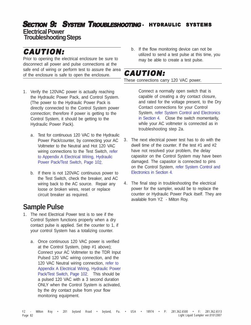
SSSSSECTIONECTIONECTIONECTIONECTION 9: 9: 9: 9: 9: S S S S SYYYYYSTEMSTEMSTEMSTEMSTEM TTTTTRRRRROUBLESHOOOUBLESHOOOUBLESHOOOUBLESHOOOUBLESHOOTINGTINGTINGTINGTING
YZ - Milton Roy • 201 Ivyland Road • Ivyland, Pa. • USA • 18974 • P: 281.362.6500 • F: 281.362.6513Page 82 Light Liquid Sampler ver.01012007
Electrical Power Troubleshooting Steps
CACACACACAUTION:UTION:UTION:UTION:UTION:Prior to opening the electrical enclosure be sure todisconnect all power and pulse connections at thesafe end of wiring or perform test to assure the areaof the enclosure is safe to open the enclosure.
1. Verify the 120VAC power is actually reachingthe Hydraulic Power Pack, and Control System.(The power to the Hydraulic Power Pack isdirectly connected to the Control System powerconnection; therefore if power is getting to theControl System, it should be getting to theHydraulic Power Pack).
a. Test for continuous 120 VAC to the HydraulicPower Pack/counter, by connecting your ACVoltmeter to the Neutral and Hot 120 VACwiring connections to the Test Switch, referto Appendix A Electrical Wiring, HydraulicPower Pack/Test Switch, Page 102.
b. If there is not 120VAC continuous power tothe Test Switch, check the breaker, and ACwiring back to the AC source. Repair anyloose or broken wires, reset or replacecircuit breaker as required.
Sample Pulse1. The next Electrical Power test is to see if the
Control System functions properly when a drycontact pulse is applied. Set the counter to 1, ifyour control System has a totalizing counter.
a. Once continuous 120 VAC power is verifiedat the Control System, (step #1 above);Connect your AC Voltmeter to the TDR InputPulsed 120 VAC wiring connection, and the120 VAC Neutral wiring connection, refer toAppendix A Electrical Wiring, Hydraulic PowerPack/Test Switch, Page 102. This should bea pulsed 120 VAC with a 3 second durationONLY when the Control System is activated,by the dry contact pulse from your flowmonitoring equipment.
b. If the flow monitoring device can not beutilized to send a test pulse at this time, youmay be able to create a test pulse.
CACACACACAUTION:UTION:UTION:UTION:UTION:These connections carry 120 VAC power.
Connect a normally open switch that iscapable of creating a dry contact closure,and rated for the voltage present, to the DryContact connections for your ControlSystem, refer System Control and Electronicsin Section 4. Close the switch momentarily,while your AC voltmeter is connected as introubleshooting step 2a.
3. The next electrical power test has to do with thedwell time of the counter. If the test #1 and #2have not resolved your problem, the delaycapasitor on the Control System may have beendamaged. The capasitor is connected to pinson the Control System, refer System Control andElectronics in Section 4.
4. The final step in troubleshooting the electricalpower for the sampler, would be to replace thecounter or Hydraulic Power Pack itself. They areavailable from YZ - Milton Roy.
- HYDRA- HYDRA- HYDRA- HYDRA- HYDRAULIC SYULIC SYULIC SYULIC SYULIC SYSTEMSSTEMSSTEMSSTEMSSTEMS

SSSSSECTIONECTIONECTIONECTIONECTION 9: 9: 9: 9: 9: S S S S SYYYYYSTEMSTEMSTEMSTEMSTEM TTTTTRRRRROUBLESHOOOUBLESHOOOUBLESHOOOUBLESHOOOUBLESHOOTINGTINGTINGTINGTING
Page 83YZ - Milton Roy • 201 Ivyland Road • Ivyland, Pa. • USA • 18974 • P: 281.362.6500 • F: 281.362.6513Light Liquid Sampler ver.01012007
Hydraulic Power
Hydraulic power is measured in terms of hydraulicpressure. There are several factors that may causeyour systems to not provide sufficient hydraulicpressure, as outlined below.
CACACACACAUTION:UTION:UTION:UTION:UTION:The Hydraulic Power Pack should NEVER beoperated without recommended oil in the reservoir.Do not operate the Power Pack at temperaturesover 140 F., or less than 0 F.
Hydraulic Power Troubleshooting Steps
1. Verify the Hydraulic Power Pack is properly filledwith the oil.
a. Remove the oil reservoir Filler/Breather Cap.
b. Check the oil level. It should be approximately1” below the lip of the oil reservoir.
c. If additional oil is required add oil of a similartype as has been previously installed in theHydraulic Power Pack.
IMPORIMPORIMPORIMPORIMPORTTTTTANT NOANT NOANT NOANT NOANT NOTE:TE:TE:TE:TE:Oil type should be 10 WT. Phillips Magna-Ahydraulic oil, automatic transmission fluid, or anyclean hydraulic oil with a viscosity range of 150-300SSU @ 100 F.
2. If the hydraulic system begins making anunusual screeching noise, and the oil level iscorrect, check and clean, or replace the reser-voir filter.
a. Drain the oil from the oil reservoir, utilizing theoil drain plug at the lower end on the oil reser-voir, opposite the power pack electrical motor.
b. Remove the (4) hex head cap screws that holdthe oil reservoir to the Power Pack couplerhousing, and slide the reservoir off.
b. Examine, clean, and/or replace the filter onthe end of the oil pump suction pipe.
3. Verify hydraulic power system pressure. Thismay be done in two ways, as detailed below.
a. Pressure Test Method #1:• Disconnect the pressure out line from the Hydraulic Power Pack, refer to illustration, page 100.• Install a pressure gage into the pressure out port from the Power Pack.
CACACACACAUTION:UTION:UTION:UTION:UTION:The use a high quality gage capable of with stand-ing at least 1,000 psi of pressure.
• Test run the Power Pack, and observe the dead headed pressure on the gage. Pressure should be between 350 psi - 400 psi.• If the pressure is not sufficient contact YZ - Milton Roy• Remove the gage, and reconnect the original tubing to the Sample Pump.• This is a bidirectional Power Pack, so now repeat the process with the pump running the other direction, and with the gage in the other port from the Power Pack.
b. Pressure Test Method #2:• Disconnect the pressure in line to the Sample Pump, from the Hydraulic Power Pack, refer to illustration, page 100.• Install an inline Tee, with a pressure gage into the pressure in port of the Sample Pump, and re-connect the tubing from the Power Pack.
CACACACACAUTION:UTION:UTION:UTION:UTION:Use a high quality gage capable of with standing atleast 1,000 psi of pressure.
- HYDRA- HYDRA- HYDRA- HYDRA- HYDRAULIC SYULIC SYULIC SYULIC SYULIC SYSTEMSSTEMSSTEMSSTEMSSTEMS

SSSSSECTIONECTIONECTIONECTIONECTION 9: 9: 9: 9: 9: S S S S SYYYYYSTEMSTEMSTEMSTEMSTEM TTTTTRRRRROUBLESHOOOUBLESHOOOUBLESHOOOUBLESHOOOUBLESHOOTINGTINGTINGTINGTING
YZ - Milton Roy • 201 Ivyland Road • Ivyland, Pa. • USA • 18974 • P: 281.362.6500 • F: 281.362.6513Page 84 Light Liquid Sampler ver.01012007
- HYDRA- HYDRA- HYDRA- HYDRA- HYDRAULIC SYULIC SYULIC SYULIC SYULIC SYSTEMSSTEMSSTEMSSTEMSSTEMS
Notes

SSSSSECTIONECTIONECTIONECTIONECTION 9: 9: 9: 9: 9: S S S S SYYYYYSTEMSTEMSTEMSTEMSTEM TTTTTRRRRROUBLESHOOOUBLESHOOOUBLESHOOOUBLESHOOOUBLESHOOTINGTINGTINGTINGTING
Page 85YZ - Milton Roy • 201 Ivyland Road • Ivyland, Pa. • USA • 18974 • P: 281.362.6500 • F: 281.362.6513Light Liquid Sampler ver.01012007
- HYDRA- HYDRA- HYDRA- HYDRA- HYDRAULIC SYULIC SYULIC SYULIC SYULIC SYSTEMSSTEMSSTEMSSTEMSSTEMS
Notes

SSSSSECTIONECTIONECTIONECTIONECTION 9: 9: 9: 9: 9: S S S S SYYYYYSTEMSTEMSTEMSTEMSTEM TTTTTRRRRROUBLESHOOOUBLESHOOOUBLESHOOOUBLESHOOOUBLESHOOTINGTINGTINGTINGTING
YZ - Milton Roy • 201 Ivyland Road • Ivyland, Pa. • USA • 18974 • P: 281.362.6500 • F: 281.362.6513Page 86 Light Liquid Sampler ver.01012007
Notes

AAAAAPPENDIXPPENDIXPPENDIXPPENDIXPPENDIX A: A: A: A: A: IIIIILLLLLLLLLLUSTRAUSTRAUSTRAUSTRAUSTRATIONSTIONSTIONSTIONSTIONS
Page 87YZ - Milton Roy • 201 Ivyland Road • Ivyland, Pa. • USA • 18974 • P: 281.362.6500 • F: 281.362.6513Light Liquid Sampler ver.01012007
PNR-2P Sample Pump,AssembledFigure 71
EXHAUST FILTER, 1/8" SS
LPR/PNR INLET CHECK DART
SEAL W/SS SPRING TFE/GLASS/MOLY 3/8" ID
1/8" ALLEN HEAD PLUG SS
PNR-2 UP/MID/CV BODY ASSY
PNR-2 UP/MID/CV BODY ASSY
PNR-2 PLUNGER BUSHING 3/8
PNR-2 UP/MID/CV BODY ASSY
B2-1106
A2-0177
6 FLAT WASHER SS
OR -210, NITRILE
OR -010, NITRILE
6-32 x 3/16 PAN HD SS
INLET CV SPRING PNR-2
A5-2210
C0-0157
C0-0080
C3-0027
A5-2010
B2-1017
A7-0011
A6-0040
B2-1106
C4-0028
B2-1106
PRODUCT IN
STROKE SCALE, 3/8" PD PUMP
PNR-2 ACTUATOR CYLINDER
PNR-2 STROKE SCREW ASSY
PNR-2 STROKE SCALE IND
B2-1003
ACTUATION SUPPLY
3/8-24 JAM NUT, SS
PNR-2 PNEU ACT PISTON
C0-0118
B2-1009
5/16 FLAT WASHER, SS
MCONN, 1/4T 1/8P, SS
5/16-18 x 5/8" HHCS SS
A1-0003
C0-0017
C0-0098
B2-1002
D5-0020
PRODUCT OUT
BV-200 ASSY (STD)
VALVE, PURGE, SS 1/8" NUPRO
MCONN, 1/8T 1/8P, SS
1/8" 316 SEAMLESS .035W
MCONN, 1/8T 1/8P, SS
PNR-2 CHECK VALVE FOR USE W/ BV-200
A1-0099
C7-0044
1/8" SS PLUG
A3-0161
B2-1520
B2-1529
A1-0099
1/4-28UNF x 1/2" BHCS SS
3/8 STAR WASHER (EXT) SS
PD PUMP PACKING
5/16-24 JAM NUT SS
PNR-2 PACKING GLAND NUT
PNR-2P PLUNGER RTN SPRING CAD PLATED
U-CUP WIPER SEAL (PNR-2 ACT PISTON)
PNR-2 3/8 CERAMIC PLUNGER
PNR-2 ACORN NUT
B2-1102
C3-0016
C0-0117
A6-0036
A6-0035
B2-1006
C0-0108
B2-1001
A2-0177
B2-1041
13377 (3)

AAAAAPPENDIXPPENDIXPPENDIXPPENDIXPPENDIX A: A: A: A: A: IIIIILLLLLLLLLLUSTRAUSTRAUSTRAUSTRAUSTRATIONSTIONSTIONSTIONSTIONS
YZ - Milton Roy • 201 Ivyland Road • Ivyland, Pa. • USA • 18974 • P: 281.362.6500 • F: 281.362.6513Page 88 Light Liquid Sampler ver.01012007
LPR-2P Sample Pump,AssembledFigure 72
PRODUCT IN
EXHAUST FILTER, 1/8" SS
1/8" ALLEN HEAD PLUG SS
INLET CV SPRING LPR-2
6-32 x 3/16 PAN HD SS
6 FLAT WASHER SS
LPR-2 UP/MID/CV BODY ASSY
LPR-2 PLUNGER BUSHING 3/8
SEAL W/SS SPRING TFE/GLASS/MOLY 3/8" ID
LPR-2 UP/MID/CV BODY ASSY
LPR/PNR INLET CHECK DART
LPR-2 UP/MID/CV BODY ASSYB2-1105
A2-0177
B2-1017
A5-2010
C3-0027
C0-0080
C0-0157
A5-2210
OR -010, NITRILE
OR -210, NITRILE
C4-0028
B2-1105
A6-0040
B2-1105
A7-0011
PRODUCT LOOP
LPR-2 STROKE SCALE IND
5/16-18 x 5/8" HHCS SS
MCONN, 1/4T 1/8P, SS
5/16 FLAT WASHER, SS
LPR-2 PNEU ACT PISTON
ACTUATION SUPPLY
STROKE SCALE, 3/8" PD PUMP
LPR-2 STROKE SCREW ASSY
LPR-2 ACTUATOR CYLINDER
B2-1003
B2-1009
C0-01183/8-24 JAM NUT, SS
C0-0098
C0-0017
B2-1041
A1-0003
D5-0020
B2-1002
PRODUCT OUT
A1-0099
B2-1520
A3-0161
MCONN, 1/8T 1/8P, SS
1/8" 316 SEAMLESS .035W
MCONN, 1/8T 1/8P, SS
LPR-2 CHECK VALVE FOR BV-200
VALVE, PURGE, SS 1/8" NUPRO
BV-200 ASSY (STD)
A1-0099
C7-0044
A2-01771/8" SS PLUG
B2-1529
5/16-24 JAM NUT SS
LPR-2 ACORN NUT
PD PUMP PACKING
1/4-28UNF x 1/2" BHCS SS
LPR-2 3/8 CERAMIC PLUNGER
U-CUP WIPER SEAL (LPR-2 ACT PISTON)
LPR-2P PLUNGER RTN SPRING CAD PLATED
3/8 STAR WASHER (EXT) SS
LPR-2 PACKING GLAND NUT
A6-0036
C0-0117
13377 (3)
C3-0016
B2-1102
B2-1006
A6-0035
B2-1001
C0-0108

AAAAAPPENDIXPPENDIXPPENDIXPPENDIXPPENDIX A: A: A: A: A: IIIIILLLLLLLLLLUSTRAUSTRAUSTRAUSTRAUSTRATIONSTIONSTIONSTIONSTIONS
Page 89YZ - Milton Roy • 201 Ivyland Road • Ivyland, Pa. • USA • 18974 • P: 281.362.6500 • F: 281.362.6513Light Liquid Sampler ver.01012007
PNR-2H Sample Pump,AssembledFigure 73
C0-0108
B2-1001
A6-0035
B2-1041
B2-1008
A6-0036
C0-0117
B2-1102
B2-1006
ACORN NUT
13377 (3)
5/16-24 JAM NUT SS
PACKING GLAND NUT
3/8 STAR WASHER (EXT), SS
ACTUATOR CYLINDER
HYD ACTUATOR PISTON
U-CUP WIPER SEAL
PD PUMP PACKING
PNR-2 3/8 CERAMIC PLUNGER
1/4-28UNF x 1/2" BHCS SS
PLUNGER RETURN SPRING
B2-1520BV-200 ASSY.
PURGE VALVE
B2-1103
C4-0028EXHAUST FILTER, 1/8" SS
PRODUCT OUT
CHECK VALVE FOR BV-200
RETURN SPRING SUPPORTC3-0026
B2-1002STROKE SCALE IND
D5-0020
C0-0098
B2-1003
5/16 FLAT WASHER, SS
5/16-18 x 5/8" HHCS, SS
STROKE SCREW ASSY
A1-0003
B2-1010
C0-0080
C3-0027
BUMP VALVE DART
6 FLAT WASHER SS
MCONN, 1/4T 1/8P, SS
C0-0118
B2-1106
A5-2232
3/8-24 JAM NUT, SS
OR -232 NITRILE
C0-00566-32 x 1/2" SHCS, SS
BUMP DART SPRING
C0-0017
STROKE SCALE, 3/8" PD PUMP
PNR-2 UP/MID/CV BODY ASSY
B2-1106
MCONN, 1/4T 1/8P, SSA1-0003
A7-0011
A6-0037 PLUNGER BUSHING 3/8
SEAL, 3/8" PLUNGER
A6-0040
A5-2010
B2-1017OR -010, NITRILE
SEAL 3/8" ID
A2-0177ALLEN HEAD PLUG
B2-1106
A5-2210
C0-0080
OR -210, NITRILE
6 FLAT WASHER SS
C0-01576-32 x 3/16 PAN HD SS
C3-0027INLET CV SPRING PNR-2
PNR INLET CHECK DART
PNR-2 UP/MID/CV BODY ASSY
PNR-2 UP/MID/CV BODY ASSY

AAAAAPPENDIXPPENDIXPPENDIXPPENDIXPPENDIX A: A: A: A: A: IIIIILLLLLLLLLLUSTRAUSTRAUSTRAUSTRAUSTRATIONSTIONSTIONSTIONSTIONS
YZ - Milton Roy • 201 Ivyland Road • Ivyland, Pa. • USA • 18974 • P: 281.362.6500 • F: 281.362.6513Page 90 Light Liquid Sampler ver.01012007
LPR-2H Sample Pump,AssembledFigure 74
LPR-2 UP/MID/CV BODY ASSY
6-32 x 3/16 PAN HD SS
#6 FLAT WASHER
ORING -210 NITRILE
INLET CHECK VALVE SPRING
ORING -010 NITRILE
INLET CHECK DART
1/8" HEX HEAD PLUG SS
LPR-2 UP/MID/CV BODY ASSY
3/8" SEAL W/SS SPRING TFE/GLASS/MOLY
3/8" PLUNGER BUSHING
3/8" PLUNGER SEAL MOLY W/POLYPAK O-RING
MCONN 1/4T x 1/8P SS
A5-2210
C0-0157
B2-1105
C0-0080
A2-0177
B2-1105
C3-0027
A5-2010
B2-1017
A6-0037
A6-0040
A7-0011
A1-0003
STROKE SCALE
LPR-2 UP/MID/CV BODY ASSY
ORING -232 NITRILE
3/8-24 JAM NUT SS
6-32 x 1/2 SHCS SS
#6 FLAT WASHER
BUMP DART SPRING
BUMP VALVE DART
5/16 FLAT WASHER
5/16-18 x 5/8" HHCS, SS
STROKE SCREW ASSY.
STROKE SCALE IND.
MCONN 1/4T x 1/8P SS
C0-0017
C0-0118
C0-0056
B2-1105
A5-2232
C0-0080
C3-0027
B2-1010
A1-0003
B2-1002
C0-0017
B2-1003
D5-0020
C3-0026LPR-2 3/8 RETURN SPRING SUPPORT
A1-0099MCONN, 1/8T 1/8P, SS
EXHAUST FILTER1/8" SSC4-0028
B2-1103
MCONN, 1/8T 1/8P, SSA1-0099
1/8" 316 SEAMLESS .035W
C7-0044
VALVE, PURGE SS 1/8" NUPRO
LPR-2 CHECK VALVE FOR BV-200B2-1529
BV-200L ASSY (STD)
A3-0161
B2-1530
LPR-2H PLUNGER RETURN SPRING
1/4-28UNF x 1/2" BHCS SS
LPR-2 PACKING GLAND NUT
LPR-2 3/8 CERAMIC PLUNGER
PUMP ACTUATOR CYLINDER
3/8 STAR WASHER (EXT), SS
LPR-2 HYD ACTUATOR PISTON
U-CUP WIPER SEAL (LPR-2 ACT PISTON)
B2-1006
13377 (3)
B2-1102
A6-0036
C0-0117
PD PUMP PACKING
B2-1041
B2-1008
A6-0035
LPR-2 ACORN NUT
5/16-24 JAM NUT SSC0-0108
B2-1001
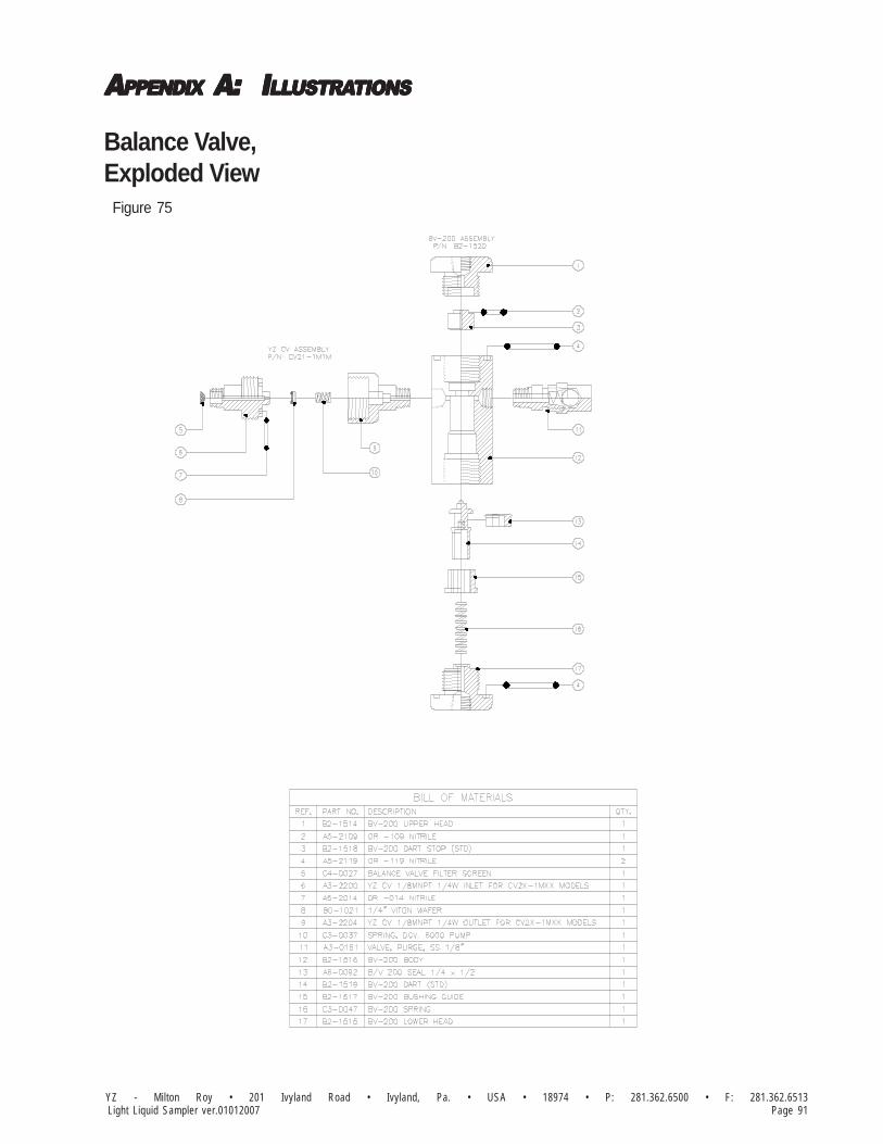
AAAAAPPENDIXPPENDIXPPENDIXPPENDIXPPENDIX A: A: A: A: A: IIIIILLLLLLLLLLUSTRAUSTRAUSTRAUSTRAUSTRATIONSTIONSTIONSTIONSTIONS
Page 91YZ - Milton Roy • 201 Ivyland Road • Ivyland, Pa. • USA • 18974 • P: 281.362.6500 • F: 281.362.6513Light Liquid Sampler ver.01012007
Balance Valve,Exploded View Figure 75
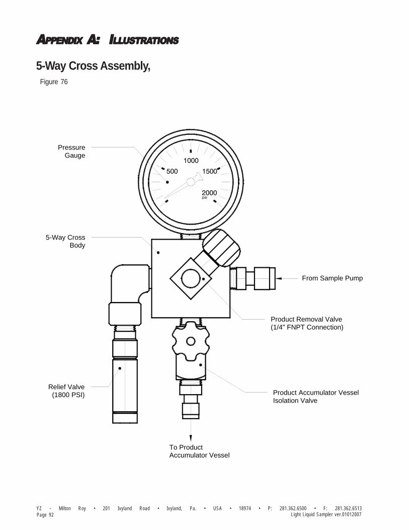
AAAAAPPENDIXPPENDIXPPENDIXPPENDIXPPENDIX A: A: A: A: A: IIIIILLLLLLLLLLUSTRAUSTRAUSTRAUSTRAUSTRATIONSTIONSTIONSTIONSTIONS
YZ - Milton Roy • 201 Ivyland Road • Ivyland, Pa. • USA • 18974 • P: 281.362.6500 • F: 281.362.6513Page 92 Light Liquid Sampler ver.01012007
5-Way Cross Assembly, Figure 76
1000
500 1500
2000psi
PressureGauge
Product Removal Valve(1/4" FNPT Connection)
Product Accumulator VesselIsolation Valve
Relief Valve(1800 PSI)
From Sample Pump
5-Way CrossBody
To ProductAccumulator Vessel

AAAAAPPENDIXPPENDIXPPENDIXPPENDIXPPENDIX A: A: A: A: A: IIIIILLLLLLLLLLUSTRAUSTRAUSTRAUSTRAUSTRATIONSTIONSTIONSTIONSTIONS
Page 93YZ - Milton Roy • 201 Ivyland Road • Ivyland, Pa. • USA • 18974 • P: 281.362.6500 • F: 281.362.6513Light Liquid Sampler ver.01012007
Pre-Charge Assembly, Figure 77
Product Accumulator Vessel Precharge Vessel
Precharge Isolation ValveWith Gauge
(By Customer)Precharge Supply

AAAAAPPENDIXPPENDIXPPENDIXPPENDIXPPENDIX A: A: A: A: A: IIIIILLLLLLLLLLUSTRAUSTRAUSTRAUSTRAUSTRATIONSTIONSTIONSTIONSTIONS
YZ - Milton Roy • 201 Ivyland Road • Ivyland, Pa. • USA • 18974 • P: 281.362.6500 • F: 281.362.6513Page 94 Light Liquid Sampler ver.01012007
Pneumatic Mixed Accumulator Vessel,Figure 78

AAAAAPPENDIXPPENDIXPPENDIXPPENDIXPPENDIX A: A: A: A: A: IIIIILLLLLLLLLLUSTRAUSTRAUSTRAUSTRAUSTRATIONSTIONSTIONSTIONSTIONS
Page 95YZ - Milton Roy • 201 Ivyland Road • Ivyland, Pa. • USA • 18974 • P: 281.362.6500 • F: 281.362.6513Light Liquid Sampler ver.01012007
Pneumatic Mixing System-Accumulator, Figure 79
Precharge Inlet HeadBushing Seal Assembly for
Bushing Seal Assembly forActuator Piston
P/N A6-0006
P/N B2-1027Bushing Assembly
Seal
P/N A6-0015
P/N A6-0006
P/N A6-0015Seal
Seal
Seal
P/N B2-1034
P/N C3-0803Snap Ring
P/N A5-2210O-Ring
Washer
WasherP/N B2-1034
P/N C3-0803Snap Ring
P/N A5-2210O-Ring
Pneumatic MixerPiston Assembly
P/N A5-2218
Cup Seals
P/N C6-2001
Bushing AssemblyP/N B2-1027
P/N B2-1028Washer
Magnets
Magnetic SpacersP/N C3-0903
Actuator PistonP/N B2-1030
P/N C0-0158Set Screw
P/N B2-1029Washer
Snap Ring
P/N A6-0124
Magnet Spacer

AAAAAPPENDIXPPENDIXPPENDIXPPENDIXPPENDIX A: A: A: A: A: IIIIILLLLLLLLLLUSTRAUSTRAUSTRAUSTRAUSTRATIONSTIONSTIONSTIONSTIONS
YZ - Milton Roy • 201 Ivyland Road • Ivyland, Pa. • USA • 18974 • P: 281.362.6500 • F: 281.362.6513Page 96 Light Liquid Sampler ver.01012007
Mixing SystemFigure 80
Explosion-ProofEnclosure w/ Electronic
Control Device
Product AccumulatorVessel
Filter Regulator
3-Way SolenoidValve
Instrument Air
Mixing Valve
(80 PSI Recommended100 PSI Max)
To Pump

AAAAAPPENDIXPPENDIXPPENDIXPPENDIXPPENDIX A: A: A: A: A: IIIIILLLLLLLLLLUSTRAUSTRAUSTRAUSTRAUSTRATIONSTIONSTIONSTIONSTIONS
Page 97YZ - Milton Roy • 201 Ivyland Road • Ivyland, Pa. • USA • 18974 • P: 281.362.6500 • F: 281.362.6513Light Liquid Sampler ver.01012007
Hydraulic Mixed Accumulator Vessel,Figure 81
O-Ring
Back Up WasherP/N A5-4439B
P/N A5-2439
Accumulator Cylinder
P/N A5-4439Glide Rings
P/N A5-2439
Back Up WasherP/N A5-4439B
O-Ring
P/N C6-3108 (1.5 Gal.)
P/N C6-3102 (1.5 Gal.)Actuator Cylinder Weldment
P/N B2-1026
P/N A6-0066
P/N C6-3302 (5 Gal.)P/N C6-3202 (3 Gal.)
Gasket
Hydralic Mixer Assy.
Magnetic Flag Strip
P/N C6-3308 (5 Gal.)P/N C6-3208 (3 Gal.)
Product Inlet Head
P/N C6-3203 (3 Gal.)
Actuator Piston
Indicator Rod andMixing Disc. Assy.
Bushing Seal Assy.See Detail
P/N C6-3303 (5 Gal.)
P/N C6-3103 (1.5 Gal.)
SealP/N A6-0014
Precharge Inlet Head
3/8-16 x 1-1/4" SHCS SS
Volume Decal
P/N D5-0102 (5 Gal.)P/N D5-0101 (3 Gal.)P/N D5-0100 (1.5 Gal.)
P/N C0-0136
P/N C6-3006
P/N C6-3007
P/N C6-3008
P/N C6-3105 (1.5 Gal.)P/N C6-3205 (3 Gal.)P/N C6-3305 (5 Gal.)
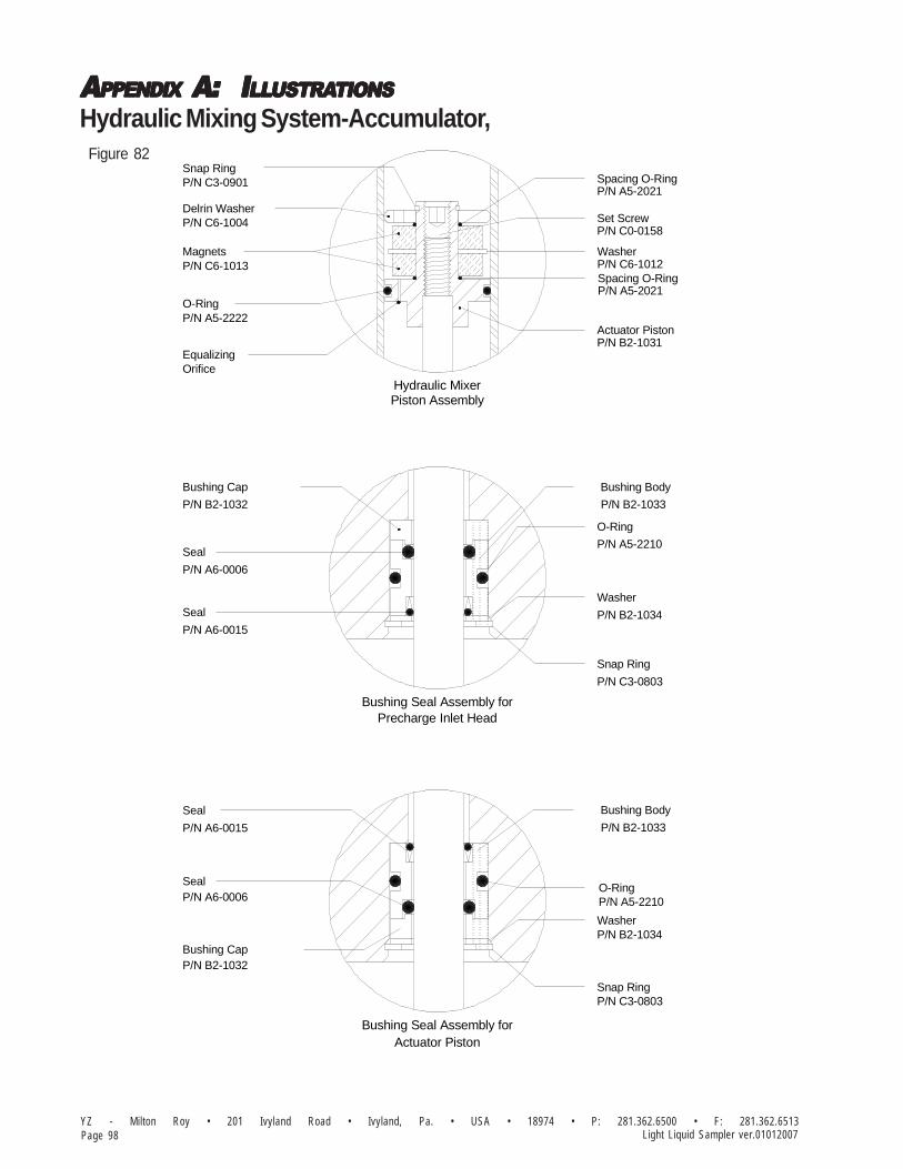
AAAAAPPENDIXPPENDIXPPENDIXPPENDIXPPENDIX A: A: A: A: A: IIIIILLLLLLLLLLUSTRAUSTRAUSTRAUSTRAUSTRATIONSTIONSTIONSTIONSTIONS
YZ - Milton Roy • 201 Ivyland Road • Ivyland, Pa. • USA • 18974 • P: 281.362.6500 • F: 281.362.6513Page 98 Light Liquid Sampler ver.01012007
Hydraulic Mixing System-Accumulator, Figure 82
O-Ring
Bushing Seal Assembly forPrecharge Inlet Head
Bushing Seal Assembly forActuator Piston
P/N B2-1032
P/N A6-0006
Bushing Cap
Seal
P/N A6-0006
P/N A6-0015
P/N A6-0015
Seal
Seal
Seal
P/N B2-1034
P/N C3-0803Snap Ring
P/N A5-2210
Washer
O-Ring
P/N B2-1034
Snap Ring
P/N C3-0803
P/N A5-2210
Washer
Hydraulic MixerPiston Assembly
P/N C6-1004Delrin Washer
P/N A5-2222
Equalizing
Bushing Cap
P/N B2-1032
P/N C6-1013
Orifice
O-Ring
Magnets
Snap Ring P/N C3-0901
P/N A5-2021
Spacing O-Ring
Actuator PistonP/N B2-1031
P/N A5-2021
P/N C6-1012
Set Screw
Washer
P/N C0-0158
Spacing O-Ring
P/N B2-1033
Bushing Body
P/N B2-1033
Bushing Body

AAAAAPPENDIXPPENDIXPPENDIXPPENDIXPPENDIX A: A: A: A: A: IIIIILLLLLLLLLLUSTRAUSTRAUSTRAUSTRAUSTRATIONSTIONSTIONSTIONSTIONS
Page 99YZ - Milton Roy • 201 Ivyland Road • Ivyland, Pa. • USA • 18974 • P: 281.362.6500 • F: 281.362.6513Light Liquid Sampler ver.01012007
Hydraulic Mixing SystemFigure 83
HydraulicPowerPack
VesselProduct Accumulator
Diverter Valve
Precharge Vessel
Precharge Supply
Test/
ModeSwitch
MixingSwitch

AAAAAPPENDIXPPENDIXPPENDIXPPENDIXPPENDIX A: A: A: A: A: IIIIILLLLLLLLLLUSTRAUSTRAUSTRAUSTRAUSTRATIONSTIONSTIONSTIONSTIONS
YZ - Milton Roy • 201 Ivyland Road • Ivyland, Pa. • USA • 18974 • P: 281.362.6500 • F: 281.362.6513Page 100 Light Liquid Sampler ver.01012007
Hydraulic Power PackFigure 84
PRESSURE ADJUSTMENTSCREW
BOTTOM VIEW
FRONT VIEW
14"NPT PRESSURE PORT
14"NPT RETURN PORT
TOP VIEW PUMP
O-RING SEAL
FILTER
38"NPT DRAIN PORT
38"NPT FILL PORT &VENT CAP PORT
38"NPT FILL PORT &VENT CAP PORT
O-RING SEAL
SUCTIONTUBE
RESERVOIR BOLTS(TYP. 4)
38"NPT DRAIN PORT
RESERVOIR BOLTS(TYP. 4)
Pressure Test #1
Pressure Test #1a

AAAAAPPENDIXPPENDIXPPENDIXPPENDIXPPENDIX A: A: A: A: A: IIIIILLLLLLLLLLUSTRAUSTRAUSTRAUSTRAUSTRATIONSTIONSTIONSTIONSTIONS
Page 101YZ - Milton Roy • 201 Ivyland Road • Ivyland, Pa. • USA • 18974 • P: 281.362.6500 • F: 281.362.6513Light Liquid Sampler ver.01012007
Hydraulic Power Pack/Test Switch
Figure 85
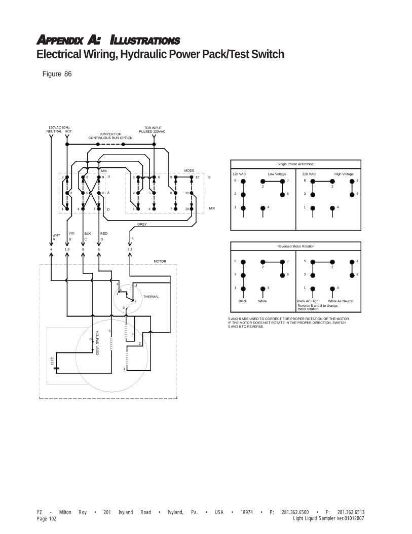
AAAAAPPENDIXPPENDIXPPENDIXPPENDIXPPENDIX A: A: A: A: A: IIIIILLLLLLLLLLUSTRAUSTRAUSTRAUSTRAUSTRATIONSTIONSTIONSTIONSTIONS
YZ - Milton Roy • 201 Ivyland Road • Ivyland, Pa. • USA • 18974 • P: 281.362.6500 • F: 281.362.6513Page 102 Light Liquid Sampler ver.01012007
Figure 86
Electrical Wiring, Hydraulic Power Pack/Test Switch
MIX MODE
U
A
D
S
MIX
PULSED 120VAC
WHTVIO BLK RED
GREY
A B C D E
THERMAL
MOTOR
CE
NT
. SW
ITC
H
ELE
C.
5
8
3
1
2
3
2
1
JJ4
4
TDR INPUT
5 AND 8 TO REVERSE.IF THE MOTOR DOES NOT ROTATE IN THE PROPER DIRECTION, SWITCH5 AND 8 ARE USED TO CORRECT FOR PROPER ROTATION OF THE MOTOR.
White Ac NeutralReverse 5 and 8 to change
Reversed Motor Rotation
WhiteBlack
5
3
1
2
Black AC High
motor rotation.
4
8
J
1
3
5
3
1
8
120 VAC
2
4
5
1
3
Single Phase w/Terminal
Low Voltage
J
220 VAC
8
4
8
2
J
4
5
High Voltage
2
J
4 1,3 8 5 2,J
3
2
1 4
6
5 8
7
9
1
2
3 6
5
4
9
8
7
12
11
10
JUMPER FORCONTINUOUS RUN OPTION
NEUTRAL HOT120VAC 60Hz

AAAAAPPENDIXPPENDIXPPENDIXPPENDIXPPENDIX A: A: A: A: A: IIIIILLLLLLLLLLUSTRAUSTRAUSTRAUSTRAUSTRATIONSTIONSTIONSTIONSTIONS
Page 103YZ - Milton Roy • 201 Ivyland Road • Ivyland, Pa. • USA • 18974 • P: 281.362.6500 • F: 281.362.6513Light Liquid Sampler ver.01012007
Z-65 Wiring Control Document Figure 87
System Installation Notes and Recommendations

AAAAAPPENDIXPPENDIXPPENDIXPPENDIXPPENDIX A: A: A: A: A: IIIIILLLLLLLLLLUSTRAUSTRAUSTRAUSTRAUSTRATIONSTIONSTIONSTIONSTIONS
YZ - Milton Roy • 201 Ivyland Road • Ivyland, Pa. • USA • 18974 • P: 281.362.6500 • F: 281.362.6513Page 104 Light Liquid Sampler ver.01012007
Z-200 Wiring Control Document Figure 88
System Installation Notes and Recommendations

AAAAAPPENDIXPPENDIXPPENDIXPPENDIXPPENDIX A: A: A: A: A: IIIIILLLLLLLLLLUSTRAUSTRAUSTRAUSTRAUSTRATIONSTIONSTIONSTIONSTIONS
Page 105YZ - Milton Roy • 201 Ivyland Road • Ivyland, Pa. • USA • 18974 • P: 281.362.6500 • F: 281.362.6513Light Liquid Sampler ver.01012007
Notes
201 Ivyland Road
Ivyland, Pa.
18974
800.653.9435
P: 281.362.6500
F: 281.362.6513
Em:
Web:
www.yzsystems.com
YZ Systems, Inc. represents and warrants that for a period of 1 year from receipt of the product: (1) the product will be free from defects in materials and workmanship; and (2)the product will perform substantially in accordance with product manuals, literature, or documentation. Any written or oral information or advice given by YZ representatives,agents, or employees will in no way increase the scope of this warranty. If the product fails to comply with the warranty set forth herein, YZ's entire liability and the customer'sexclusive remedy will be replacement of the product(s) or, at YZ's option, YZ's reasonable effort to make the product meet the warranty set forth herein. YZ disclaims all otherwarranties, either expressed or implied, including but not limited to, implied warranties or merchantability and fitness for a particular purpose, with respect to the product.This limited warranty gives you specific legal rights. You may have others, which vary from state to state. These remedies are not available outside of the United States andCanada. In no event shall YZ or its suppliers be liable for any damages whatsoever (including, without limitation, damages for loss of profits, business interruption, loss ofinformation, or other pecuniary loss) arising out of the use of or inability to use the product, even if YZ has been advised of the possibility of such damages. Information containedin this document is subject to change without notice and does not represent a commitment on the part of YZ Systems, Inc. All prices quoted are in U.S. dollars, F.O.B. Snyder, Texas.LINC, LINC Chemical Pumps, and LINC Level & Flow Switches are trademarks of YZ Systems, Inc. All other product names and/or registered trademarks are the property of theirrespective holders. YZ support services are subject to YZ's then-current prices, terms, and conditions, which are subject to change without notice. All prices and specifications, ifpublished, are subject to change without notice.
YZ Systems, Inc. represents and warrants that for a period of 3 years from receipt of the product: (1) the product will be free from defects in materials andworkmanship; and (2) the product will perform substantially in accordance with product manuals, literature, or documentation. Any written or oral information oradvice given by YZ representatives, agents, or employees will in no way increase the scope of this warranty. If the product fails to comply with the warrantyset forth herein, YZ's entire liability and the customer's exclusive remedy will be replacement of the product(s) or, at YZ's option, YZ's reasonable effort to makethe product meet the warranty set forth herein. YZ disclaims all other warranties, either expressed or implied, including but not limited to, impliedwarranties or merchantability and fitness for a particular purpose, with respect to the product. This limited warranty gives you specific legal rights.You may have others, which vary from state to state. These remedies are not available outside of the United States and Canada. In no event shall YZor its suppliers be liable for any damages whatsoever (including, without limitation, damages for loss of profits, business interruption, loss of information, or otherpecuniary loss) arising out of the use of or inability to use the product, even if YZ has been advised of the possibility of such damages. Information containedin this document is subject to change without notice and does not represent a commitment on the part of YZ Systems, Inc. All prices quoted are in U.S. dollars,F.O.B. Snyder, Texas. LINC, LINC Chemical Pumps, and LINC Level & Flow Switches are trademarks of YZ Systems, Inc. All other product names and/orregistered trademarks are the property of their respective holders. YZ support services are subject to YZ's then-current prices, terms, and conditions, whichare subject to change without notice. All prices and specifications, if published, are subject to change without notice.
YZ - MILTON ROY represents and warrants that for a period of 3 years from receipt of the product: (1) the product will be free from defects in materials andworkmanship; and (2) the product will perform substantially in accordance with product manuals, literature, or documentation. Any written or oral information oradvice given by YZ - MILTON ROY representatives, agents, or employees will in no way increase the scope of this warranty. If the product fails to comply withthe warranty set forth herein, YZ - MILTON ROY's entire liability and the customer's exclusive remedy will be replacement of the product(s) or, at YZ - MILTONROY's option, YZ - MILTON ROY's reasonable effort to make the product meet the warranty set forth herein. YZ - MILTON ROY disclaims all otherwarranties, either expressed or implied, including but not limited to, implied warranties or merchantability and fitness for a particular purpose,with respect to the product. This limited warranty gives you specific legal rights. You may have others, which vary from state to state. These remediesare not available outside of the United States and Canada. In no event shall YZ - MILTON ROY or its suppliers be liable for any damages whatsoever(including, without limitation, damages for loss of profits, business interruption, loss of information, or other pecuniary loss) arising out of the use of or inabilityto use the product, even if YZ - MILTON ROY has been advised of the possibility of such damages. Information contained in this document is subject to changewithout notice and does not represent a commitment on the part of YZ - MILTON ROY. All prices quoted are in U.S. dollars, F.O.B. Ivyland, Pa. All other productnames and/or registered trademarks are the property of their respective holders. YZ - MILTON ROY support services are subject to YZ - MILTON ROY's then-current prices, terms, and conditions, which are subject to change without notice. All prices and specifications, if published, are subject to change withoutnotice.