LiDAR in Robotics and Autonomous Systems
52
LiDAR in Robotics and Autonomous Systems I. Tsirozidis, Prof. Ioannis Pitas Aristotle University of Thessaloniki [email protected] www.aiia.csd.auth.gr Version 1.0
Transcript of LiDAR in Robotics and Autonomous Systems

LiDAR in Robotics and
Autonomous Systems
I. Tsirozidis, Prof. Ioannis Pitas
Aristotle University of Thessaloniki
www.aiia.csd.auth.gr
Version 1.0

• Introduction
• 3D scene mapping methods• Active 3D scene mapping methods
• The Time-of-Flight principle
• Pulsed wave
• Continuous-wave propagation
• Laser ToF Technology: LiDAR• LiDAR in Modern Autonomous Systems
• Radio wave Technology: RADAR
• Applications of Sonar
• Drone LiDARs• Technical Specifications of Current Model
• Alternatives for potential upgrade
• Conclusion
• References
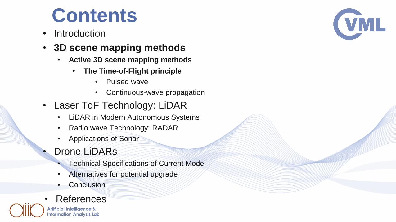
Contents

Introduction
3D scene mapping technology is -slowly but surely- becoming part of
our day to day life. To this day, there have been numerous practical
applications of 3D scene mapping , targeting a wide variety of fields
such as:
• Aeronautics
• Medical imaging
• Architecture
• Transportation
• Security
and many more…

3D scene mapping methods
3D scene mapping methods can be divided in two main
categories:
• Active 3D scene mapping methods
• Passive 3D scene mapping methods

3D scene mapping methods
Active 3D scene mapping methods
• A 3D scene is illuminated by a laser beam.
• By measuring the visual echo of the laser beam, we can obtain a
number of images, describing the 3D scene or object.
Scene Illumination from iPhone LiDAR [VEN].

3D scene mapping methods
Passive 3D scene mapping methods
• Passive methods acquire depth map information out of an object,
without user active involvement, e.g., for object illumination.
• In comparison to active methods, passive methods can be applied
to a wider range of situations.
Shape from shading [RES].

• Introduction
• 3D scene mapping methods• Active 3D scene mapping methods
• The Time-of-Flight principle
• Pulsed wave
• Continuous-wave propagation
• Laser ToF Technology: LiDAR• LiDAR in Modern Autonomous Systems
• Radio wave Technology: RADAR
• Applications of Sonar
• Drone LiDARs• Technical Specifications of Current Model
• Alternatives for potential upgrade
• Conclusion
• References
Contents

The Time-of-Flight principle
Time-of-Flight (ToF)
• In this technology, a light beam emanates from a laser source.
Time-of-Flight uses the time difference between the transmission
of a pulse and the corresponding reception of an echo, to provide
an accurate estimation of the range (distance traveled).
ToF applied to laser range-finding [EUR].

The Time-of-Flight principle
Time-of-Flight Cameras (ToF Cameras)
• ToF cameras, using an artificial LED light signal, are able to
provide range images in high frame rates and resolutions. They
have become quite popular, inexpensive and more compact.
• A disadvantage, is that they cannot yet attain the depth accuracy
offered by other types of sensors, such as laser scanners.
Industrial Helios2 Time-of-Flight Camera [THI].
• Introduction
• 3D scene mapping methods• Active 3D scene mapping methods
• The Time-of-Flight principle
• Pulsed wave
• Continuous-wave propagation
• Laser ToF Technology: LiDAR• LiDAR in Modern Autonomous Systems
• Radio wave Technology: RADAR
• Applications of Sonar
• Drone LiDARs• Technical Specifications of Current Model
• Alternatives for potential upgrade
• Conclusion
• References
Contents

The Time-of-Flight principle
The Time-of-Flight methods can be classified into two main
subcategories:
• Pulsed wave
• Continuous-wave propagation

• Introduction
• 3D scene mapping methods• Active 3D scene mapping methods
• The Time-of-Flight principle
• Pulsed wave
• Continuous-wave propagation
• Laser ToF Technology: LiDAR• LiDAR in Modern Autonomous Systems
• Radio wave Technology: RADAR
• Applications of Sonar
• Drone LiDARs• Technical Specifications of Current Model
• Alternatives for potential upgrade
• Conclusion
• References
Contents

The Time-of-Flight principle
Pulsed wave
In pulsed wave or time-delay methods, distance information is
estimated by directly measuring the time lapse between signal
emission and the corresponding echo reception, in the light sensor.
• Using the pulse flight-time, the distance (𝑑) covered, is given by:
𝑑 =cΔ𝑡
2 (1.0)
• c is the speed of light
• is the time difference between signal emission and reception

The Time-of-Flight principle
In general, systems based on time delay ToF methods are
extensively used for measuring extremely small
(𝑖𝑛 𝑡ℎ𝑒 𝑠𝑐𝑎𝑙𝑒 𝑜𝑓 0 𝑡𝑜 10 𝑚𝑚) or large (10 𝑚) field of view, thus there
are no significant applications of these methods for intermediate
distance ranges.
Pulsed-wave ToF method [PIT2020].

• Introduction
• 3D scene mapping n methods• Active 3D scene mapping methods
• The Time-of-Flight principle
• Pulsed wave
• Continuous-wave propagation
• Laser ToF Technology: LiDAR• LiDAR in Modern Autonomous Systems
• Radio wave Technology: RADAR
• Applications of Sonar
• Drone LiDARs• Technical Specifications of Current Model
• Alternatives for potential upgrade
• Conclusion
• References
Contents

The Time-of-Flight principle
Continuous-wave propagation
Methods using continuous wave-based sensors can be
classified into two, light modulation categories of waves:
• Amplitude Modulation (AM)
• Frequency Modulation (FM)

Continuous-wave propagation
Amplitude modulation (AM)
In the AM phase-shift method, range information is determined by
applying amplitude modulation and measuring the phase shift
between the emitting and the received light beams.
• Emitted signal is described by the sinusoid:
𝑠 𝑡 = sin 2𝜋𝑓𝑚𝑡 .
• 𝑓𝑚: modulation frequency.
• The signal is reflected back to the sensor, with a phase shift 𝜑:
𝑟 𝑡 = 𝑅sin 2𝜋𝑓𝑚𝑡 − 𝜑 ,
• 𝑅: reflected light intensity

Continuous-wave propagation
The distance traveled is given by the equation:
𝑑 =𝑐𝜑
4𝜋𝑓𝑚
(1.1)
• 𝑐 is the speed of light (𝑐 = 3 × 10⁸ 𝑚/𝑠)
• This calculation does not take into account the phase shift
attributed to noise and measurement errors.
Amplitude modulation phase shift ToF method [PIT2020].

Continuous-wave propagation
Frequency modulation (FM)
In the FM phase-shift method, instead of calculating the phase shift
difference, we calculate the frequency difference of the emitted and
reflected sinusoidal signals.
• We calculate the frequency difference of the signals, resulting in
the so-called beat frequency.
𝑓𝐵 = 𝑓𝑒 − 𝑓𝑟 (1.2)
• 𝑓𝑒: the emitted frequency
• 𝑓𝑟: the received frequency

Continuous-wave propagation
• By comparing the similar triangles OAB and OCD, we find:
𝑓𝐵
𝜏𝑑=
𝛥𝑓𝛵𝑟
2
(1.3)
• 𝑓𝐵: the beat frequency
• Δ𝑓 = 𝐹𝑚𝑎𝑥 – 𝐹𝑚𝑖𝑛
• 𝑇𝑟: the period of the wave.
Ramp wave modulating
frequency and resultant beat
frequency [PIT2020].

Continuous-wave propagation
• Furthermore, we also have that:
𝜏𝑑 =2𝑑
𝑐 (1.4)
• 𝜏𝑑 is the time shift of the two waves
• 𝑑 is the distance traveled by the laser
• 𝑐 is the speed of light (𝑐 = 3 × 10⁸ 𝑚/𝑠)

Continuous-wave propagation
• By solving the previous two equations (1.3), (1.4), we can calculate
the distance:
𝑑 =𝑓𝐵
4Δf𝑐𝑇𝑟 (1.5)
• The minimum and maximum distance values can be described as:
𝑑𝑚𝑖𝑛 =𝑐
4𝛥𝑓𝑑𝑚𝑎𝑥 =
𝑐𝑇𝑟
4(1.6)

• Introduction
• 3D scene mapping methods• Active 3D scene mapping methods
• The Time-of-Flight principle
• Pulsed wave
• Continuous-wave propagation
• Laser ToF Technology: LiDAR• LiDAR in Modern Autonomous Systems
• Radio wave Technology: RADAR
• Applications of Sonar
• Drone LiDARs• Technical Specifications of Current Model
• Alternatives for potential upgrade
• Conclusion
• References
Contents

LiDAR
L i g h t D e t e c t i o n A n d R a n g i n g
LiDAR is a remote detection and ranging method that that utilizes
lasers, and emits infrared light pulses to measure how long they take
to come back after hitting nearby objects.
• The time between the output laser pulse and the reflected pulse
allows the LiDAR sensor to calculate the distance to each object
precisely, based on the speed of light.
LiDAR's potential integration into vehicles [MES].

LiDAR
L i g h t D e t e c t i o n A n d R a n g i n g
• LiDAR captures millions of such precise distance measurement
points each second, from which a 3D matrix of its environment can
be produced.
• Information on objects’ position, shape, and behavior can be
obtained from this comprehensive mapping of the environment.
LiDAR mapping of the top view of a building [SAN].

• Introduction
• 3D scene mapping methods• Active 3D scene mapping methods
• The Time-of-Flight principle
• Pulsed wave
• Continuous-wave propagation
• Laser ToF Technology: LiDAR• LiDAR in Modern Autonomous Systems
• Radio wave Technology: RADAR
• Applications of Sonar
• Drone LiDARs• Technical Specifications of Current Model
• Alternatives for potential upgrade
• Conclusion
• References
Contents

LiDAR in Modern
Autonomous SystemsAutonomous Systems
In robotics, an Autonomous System describes a machine that performs
behaviors or tasks with a high degree of autonomy (without external influence).
Autonomous systems are considered a subfield of artificial intelligence,
computer vision, and information engineering.
Amazon’s Prime Autonomous Delivery Robot [WIR].

LiDAR in Modern
Autonomous SystemsAutonomous Vehicles
LiDAR acts as an eye of the
self-driving vehicles. It
provides them a 360-degree
view of the surrounding that
precisely estimates external
factors. Continuously rotating
LiDAR system sends
thousands of laser pulses
every second.
LiDAR in autonomous Vehicles [GEO].

LiDAR in Modern
Autonomous SystemsAutonomous Drones in
Archeology and Structure
Building
Autonomous Drones, using
LiDAR technology are able to
map an area, analyze
structure data, and perform
accurate measurements.
3D Infrastructure scanned by Drone’s LiDAR [RED].

LiDAR in Modern
Autonomous SystemsSecurity Solutions
Security applications of the
future will be smart, efficient,
and automated. LiDAR-based
sensors provide centimeter-
level distance measurement
data to facilitate highly reliable
object detection and tracking.
Object Tracking in Airports using LiDAR [VEL].

LiDAR in Modern
Autonomous SystemsSecurity Solutions
Accurate, real-time notification in
airports, retail, intersections,
both private and public spaces.
LiDAR will play a key role in
enabling the next generation of
security solutions.
Motion Detection using LiDAR [VEL].

• Introduction
• 3D scene mapping methods• Active 3D scene mapping methods
• The Time-of-Flight principle
• Pulsed wave
• Continuous-wave propagation
• Laser ToF Technology: LiDAR• LiDAR in Modern Autonomous Systems
• Radio wave Technology: RADAR
• Applications of Sonar
• Drone LiDARs• Technical Specifications of Current Model
• Alternatives for potential upgrade
• Conclusion
• References
Contents

RADAR
R a d i o D e t e c t i o n A n d R a n g i n g
RADAR, Radio Detection and Ranging, uses radio waves to estimate
range.
• A RADAR system consists of a transmitter producing
electromagnetic waves, a transmitting antenna, a receiving
antenna and a receiver that determines the object’s properties.
• Radio waves from the transmitter reflect off the object and return to
the receiver, giving information about the object’s location and
speed.
Long-range radar antenna,
used to track space objects
[AUD].

• Introduction
• 3D scene mapping methods• Active 3D scene mapping methods
• The Time-of-Flight principle
• Pulsed wave
• Continuous-wave propagation
• Laser ToF Technology: LiDAR• LiDAR in Modern Autonomous Systems
• Radio wave Technology: RADAR
• Applications of Sonar
• Drone LiDARs• Technical Specifications of Current Model
• Alternatives for potential upgrade
• Conclusion
• References
Contents

Sonar
S o u n d N a v i g a t i o n A n d R a n g i n g
Sonar, is helpful for exploring and mapping the ocean because sound
waves travel farther in the water than do radar and light waves.
• Scientists primarily use sonar to develop nautical charts, locate
underwater hazards to navigation, search for and map objects on
the seafloor such as shipwrecks, and map the seafloor itself
Sonar
S o u n d N a v i g a t i o n A n d R a n g i n g
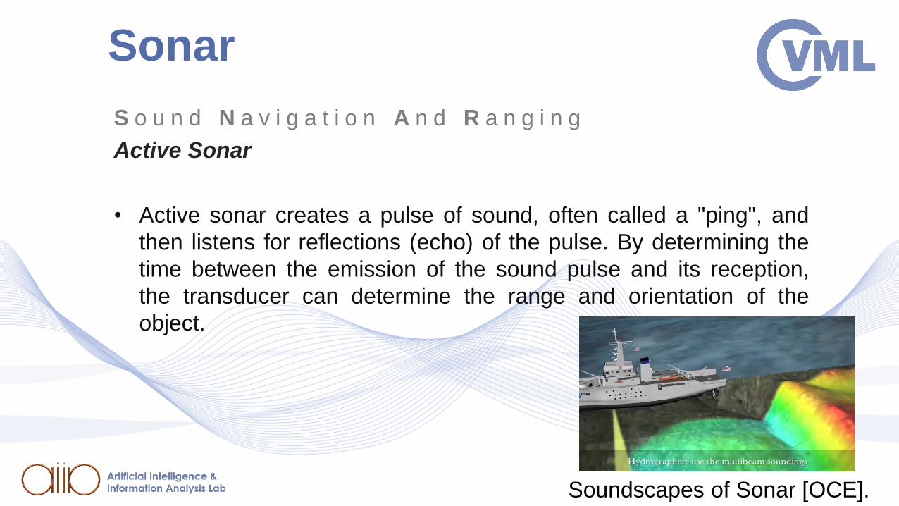
Active Sonar
• Active sonar creates a pulse of sound, often called a "ping", and
then listens for reflections (echo) of the pulse. By determining the
time between the emission of the sound pulse and its reception,
the transducer can determine the range and orientation of the
object.
Soundscapes of Sonar [OCE].

• Introduction
• 3D scene mapping methods• Active 3D scene mapping methods
• The Time-of-Flight principle
• Pulsed wave
• Continuous-wave propagation
• Laser ToF Technology: LiDAR• LiDAR in Modern Autonomous Systems
• Radio wave Technology: RADAR
• Applications of Sonar
• Drone LiDARs• Technical Specifications of Current Model
• Alternatives for potential upgrade
• Conclusion
• References
Contents

Drone’s HW: LiDAR
LEDDAR M16 LiDAR [LED].
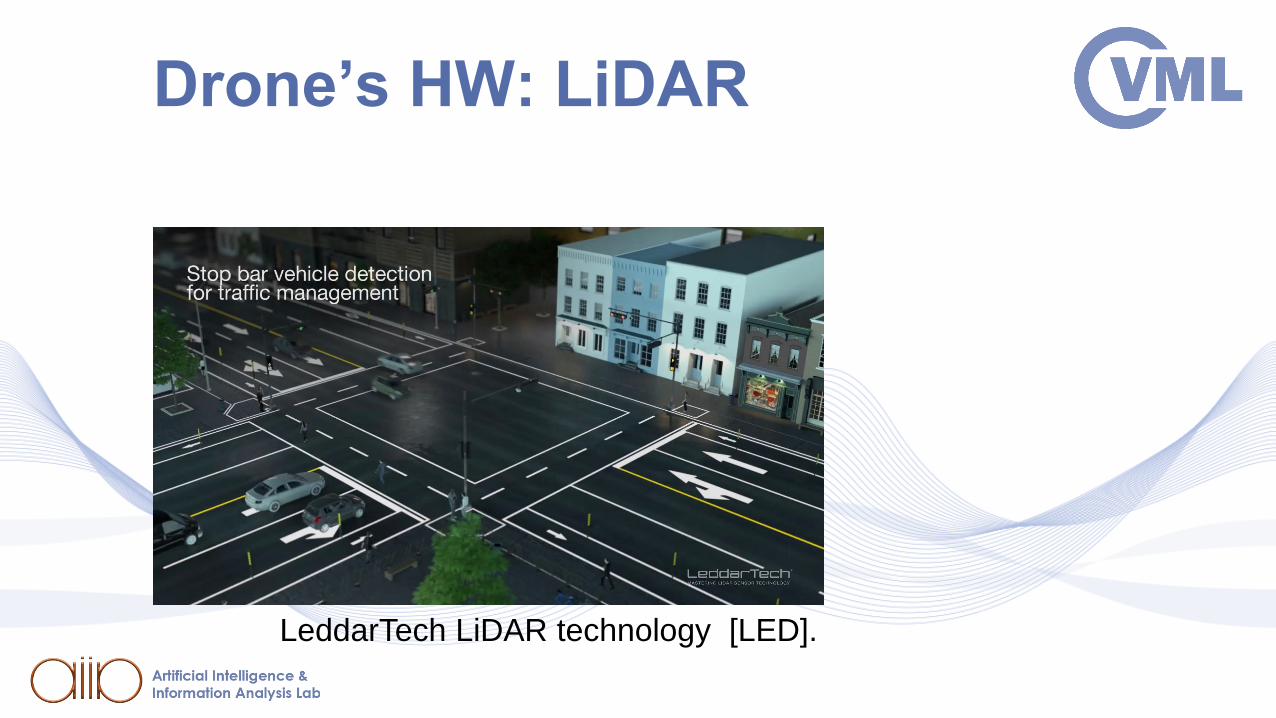
Drone’s HW: LiDAR
LeddarTech LiDAR technology [LED].

• Introduction
• 3D scene mapping methods• Active 3D scene mapping methods
• The Time-of-Flight principle
• Pulsed wave
• Continuous-wave propagation
• Laser ToF Technology: LiDAR• LiDAR in Modern Autonomous Systems
• Radio wave Technology: RADAR
• Applications of Sonar
• Drone LiDARs• Technical Specifications of Current Model
• Alternatives for potential upgrade
• Conclusion
• References
Contents

Technical Specifications of
Current LiDAR Model

Technical Specifications of
Current LiDAR Model
Average Horizontal FOV (°)
LSR: 51.5°
LED: 39.5°
Average Vertical FOV (°)
LSR: 2.3°
LED: 4.6°
MAX Horizontal FOV (°)
LSR: 99° LED: 99°
MAX Vertical FOV (°)
LSR: 3.0° LED: 8°

Technical Specifications of
Current LiDAR Model
Average Retro-reflector1 (m)
LSR:
LED:
93.1m
70 m
Average White 90% (m)
LSR:
LED:
24.5m
20.8 m
Average Gray 18% (m)
LSR:
LED:
14.8m
14.5 m

• Introduction
• 3D scene mapping methods• Active 3D scene mapping methods
• The Time-of-Flight principle
• Pulsed wave
• Continuous-wave propagation
• Laser ToF Technology: LiDAR• LiDAR in Modern Autonomous Systems
• Radio wave Technology: RADAR
• Applications of Sonar
• Drone LiDARs• Technical Specifications of Current Model
• Alternatives for potential upgrade
• Conclusion
• References
Contents

Drone’s HW: LiDAR
Does the team need an upgrade/ alternative?

Drone’s HW: LiDAR
Velodyne’s alternative

Velodyne’s feature
is superior
Velodyne’s
feature satisfies
Velodyne’s
feature is inferior

• Introduction
• 3D scene mapping methods• Active 3D scene mapping methods
• The Time-of-Flight principle
• Pulsed wave
• Continuous-wave propagation
• Laser ToF Technology: LiDAR• LiDAR in Modern Autonomous Systems
• Radio wave Technology: RADAR
• Applications of Sonar
• Drone LiDARs• Technical Specifications of Current Model
• Alternatives for potential upgrade
• Conclusion
• References
Contents

Conclusion
• Given that the experiment environment, is an area of approximately 35 x 15 square
meters, our LiDAR range satisfies to cover that distance.
• The viewing angles may not cover 360 or 180 degrees rotation, but they do cover
100 degrees rotation horizontally.
• Our LEDDAR M16 LiDAR has lesser Power Consumption, and weights significantly
less.
• Velodyne’s LiDARs output UDP packets over Ethernet, which is convenient.
Overall, if an upgrade was to be scheduled, it would mainly concern FOV Rotations,
both vertical and Horizontal.

• Introduction
• 3D scene mapping methods• Active 3D scene mapping methods
• The Time-of-Flight principle
• Pulsed wave
• Continuous-wave propagation
• Laser ToF Technology: LiDAR• LiDAR in Modern Autonomous Systems
• Radio wave Technology: RADAR
• Applications of Sonar
• Drone’s HW: LiDAR• Technical Specifications of Current Model
• Alternatives for potential upgrade
• Conclusion
• References
Contents

References[PIT2020] I. Pitas, “Computer vision”, Createspace/Amazon, in press.
[PIT2000] I. Pitas, Digital Image Processing Algorithms and Applications, J. Wiley, 2000.
[VEN] venturebeat.com
[RES] researchgate.net/journal/0921-8890_Robotics_and_Autonomous_Systems
[LED] leddartech.com/app/uploads/dlm_uploads/2018/04/Leddar_M16_specsheet_2020_EN-1.pdf[VEL] velodynelidar.com/blog/guide-to-lidar-wavelengths/
[MES] mes-insights.com/lidar-systems-costs-integration-and-major-manufacturers-a-908358/
[SAN] sanborn.com/mobile-lidar/
[SCI] sciencedirect.com/journal/robotics-and-autonomous-system
[GEO] geospatialworld.net/blogs/how-drone-based-lidar-is-hcanging-the-game/
[JOU] journals.elsevier.com/robotics-and-autonomous-systems
[OCE] oceanservice.noaa.gov
[SEM] semcon.com/offerings/applied-autonomy
[WIR] https://www.wired.com/story/lidar-self-driving-cars-luminar-video/
[RED] https://www.redboxsurveys.co.uk/
[AUD] audubon.org
[EUR] euresearcher.com