Level 0, 1, 2 & 3 Energy Audits - PERTANLevel 1 Audit Actions by Army Audit Team Leader Finalize...
77
Level 0, 1, 2 & 3 Energy Audits Alfred Woody, PE Ventilation/Energy Applications, PLLC Norton Shores, Michigan 231 798 3536
Transcript of Level 0, 1, 2 & 3 Energy Audits - PERTANLevel 1 Audit Actions by Army Audit Team Leader Finalize...

Level 0, 1, 2 & 3 Energy Audits
Alfred Woody, PEVentilation/Energy Applications, PLLCNorton Shores, Michigan231 798 3536
Overview
Audit levelsPlanning Information sourcesActivities during site visitDescription of audit reportExamples of debriefing material, ECM write-ups

Energy Assessment Audit Phases
Level 0 – Initial site contact and audit planningLevel 1 – Identification of potential ECM’s in selected buildings – order of magnitude calculations to prioritize selectionLevel 2 – Detailed analysis of selected ECM’s from level 1 analysisLevel 3 – Engineering design, project implementation followed by performance verification
Level 0 Audit
Site visit by key Army personnel to introduce the concept to the site personnel and to begin planning for the analysis.Tour of site to observe major energy users and conceive potential areas of waste and inefficiency.Observation documented by photographs and written report.
Level 0 Audit Continued
Planning of the week long Level 1 audit with the following actions:
Selecting of buildings/energy systems to be emphasized Identifying the skills/expertise needed by level 1 assessment teamDetermining schedule for weeklong site surveyRequesting relevant site information
Energy use & cost historyBuilding and site energy system dataCurrent energy management program and future plansFuture site plan and proposed construction

Level 1 Audit
Actions by Army Audit Team LeaderFinalize audit team selectionMake lodging arrangementsCoordinate information required for survey team site access Distribute preliminary information
Site energy use dataWeather data for siteReal property data for site buildingsPrevious site energy studies, reports and planning documents

Fort Campbell Buildings to Visit
Building Issues Team Day
?? EMCS System DU, CB, AW
6627, 7152, 7156, 7161, 7251, 7243, 7245, 7249, 7206
Hangers to have $2Million Renovation each. Bold = out years AW, CB
2700 Command and Control Building has Heating & Cooling Issues, zone control. Not on EMCS AW, CB
71010 Energy Hog DU, CB, AW
6559 Helicopter Simulator
??New Water Plant (Designed, but not constructed?), although privately run, it's high demand might invite demand limiting. CH@Mhill POC: Robert Neath.
?? Two 2250 KW generators can be run 360 hours/.year. Help with Load shedding?
7267? Simulator bldg. Heat/Cool issues
7268, 7272? South facing; Solar opportunities? Lighting MH DP
7034 Barracks. Issues?
7037 Fitness center. Look at Solar DHW heat DP
4000 Barracks to be renovated soon
6225 Training building has heat/cool control issues
6000 Series Barracks ??
3200 Series Barracks ??
2191 Indoor Pool - Solar Heat? DP
Bio-Mass Plant? DP
Dining Facilities Hoods, HVAC, etc. DU, CB, AW
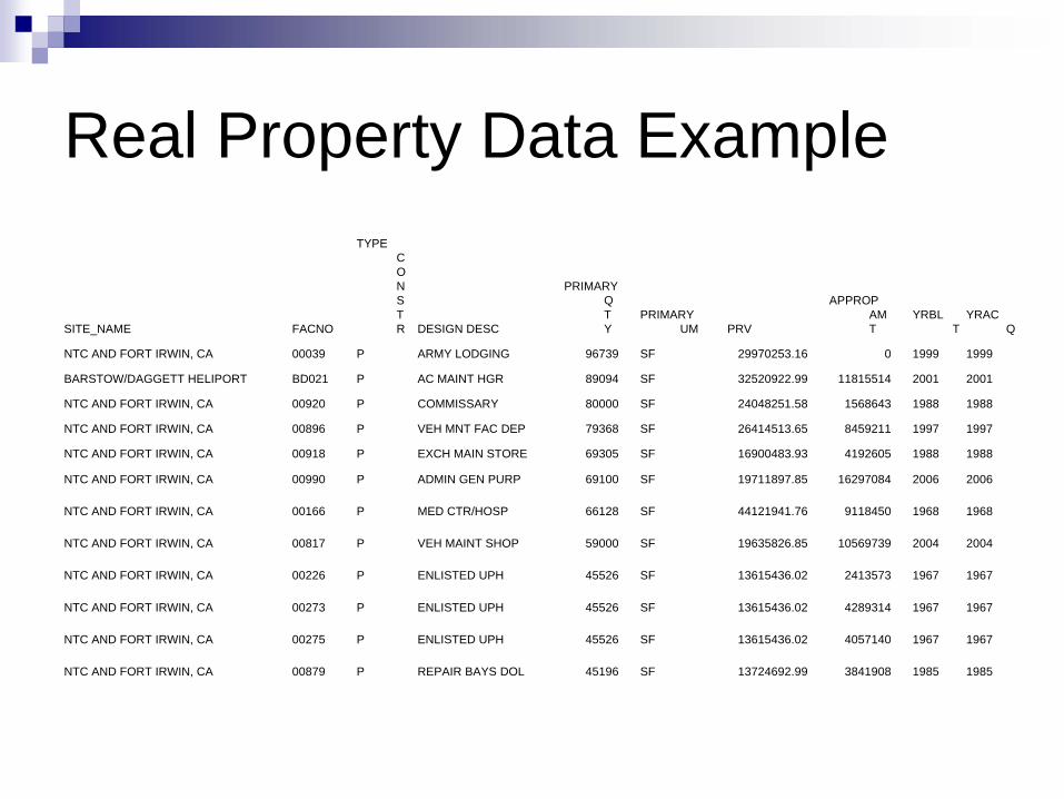
Real Property Data Example
SITE_NAME FACNO
TYPE C O N S T R DESIGN DESC
PRIMARY Q T Y
PRIMARY UM PRV
APPROP AM T
YRBL T
YRAC Q
NTC AND FORT IRWIN, CA 00039 P ARMY LODGING 96739 SF 29970253.16 0 1999 1999
BARSTOW/DAGGETT HELIPORT BD021 P AC MAINT HGR 89094 SF 32520922.99 11815514 2001 2001
NTC AND FORT IRWIN, CA 00920 P COMMISSARY 80000 SF 24048251.58 1568643 1988 1988
NTC AND FORT IRWIN, CA 00896 P VEH MNT FAC DEP 79368 SF 26414513.65 8459211 1997 1997
NTC AND FORT IRWIN, CA 00918 P EXCH MAIN STORE 69305 SF 16900483.93 4192605 1988 1988
NTC AND FORT IRWIN, CA 00990 P ADMIN GEN PURP 69100 SF 19711897.85 16297084 2006 2006
NTC AND FORT IRWIN, CA 00166 P MED CTR/HOSP 66128 SF 44121941.76 9118450 1968 1968
NTC AND FORT IRWIN, CA 00817 P VEH MAINT SHOP 59000 SF 19635826.85 10569739 2004 2004
NTC AND FORT IRWIN, CA 00226 P ENLISTED UPH 45526 SF 13615436.02 2413573 1967 1967
NTC AND FORT IRWIN, CA 00273 P ENLISTED UPH 45526 SF 13615436.02 4289314 1967 1967
NTC AND FORT IRWIN, CA 00275 P ENLISTED UPH 45526 SF 13615436.02 4057140 1967 1967
NTC AND FORT IRWIN, CA 00879 P REPAIR BAYS DOL 45196 SF 13724692.99 3841908 1985 1985

Weather Data

Level 1 Audit
Actions by Audit Team membersMake travel arrangementsReview distributed site information
Level 0 report site energy use data Weather data for sitePrevious site energy studies, reports and planning documents
Gather proper survey tools and supporting information

Fort Hood Level 0 EEAP Energy Assessment Trip Report 26 March, 2008
Directions to Bobby’s Office: From main gate, turn left at first light on Tank Destroyer. Go about 1 mile to 77th street and turn left. Bldg 4219.Contacts
Bobby LynnDick Strohl [email protected] (254) 535-2875Michelle Ann Lenis, Electrical Engineer, DPW building room 63 (254) 288-5220 [email protected]
Blended electric rate 9.3 cents/KWH$4/Decatherm Natural gasObtained list of buildings to be renovated from Michelle Lenis
Building Notes11007
Double pane windowsMasonary block walls
9576Offices not air conditioned
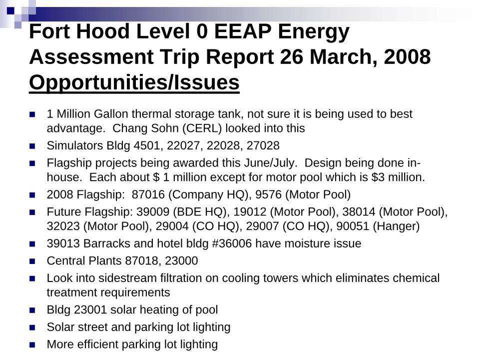
Fort Hood Level 0 EEAP Energy Assessment Trip Report 26 March, 2008 Opportunities/Issues
1 Million Gallon thermal storage tank, not sure it is being used to best advantage. Chang Sohn (CERL) looked into thisSimulators Bldg 4501, 22027, 22028, 27028Flagship projects being awarded this June/July. Design being done in-house. Each about $ 1 million except for motor pool which is $3 million.2008 Flagship: 87016 (Company HQ), 9576 (Motor Pool)Future Flagship: 39009 (BDE HQ), 19012 (Motor Pool), 38014 (Motor Pool), 32023 (Motor Pool), 29004 (CO HQ), 29007 (CO HQ), 90051 (Hanger)39013 Barracks and hotel bldg #36006 have moisture issueCentral Plants 87018, 23000Look into sidestream filtration on cooling towers which eliminates chemical treatment requirementsBldg 23001 solar heating of poolSolar street and parking lot lightingMore efficient parking lot lighting
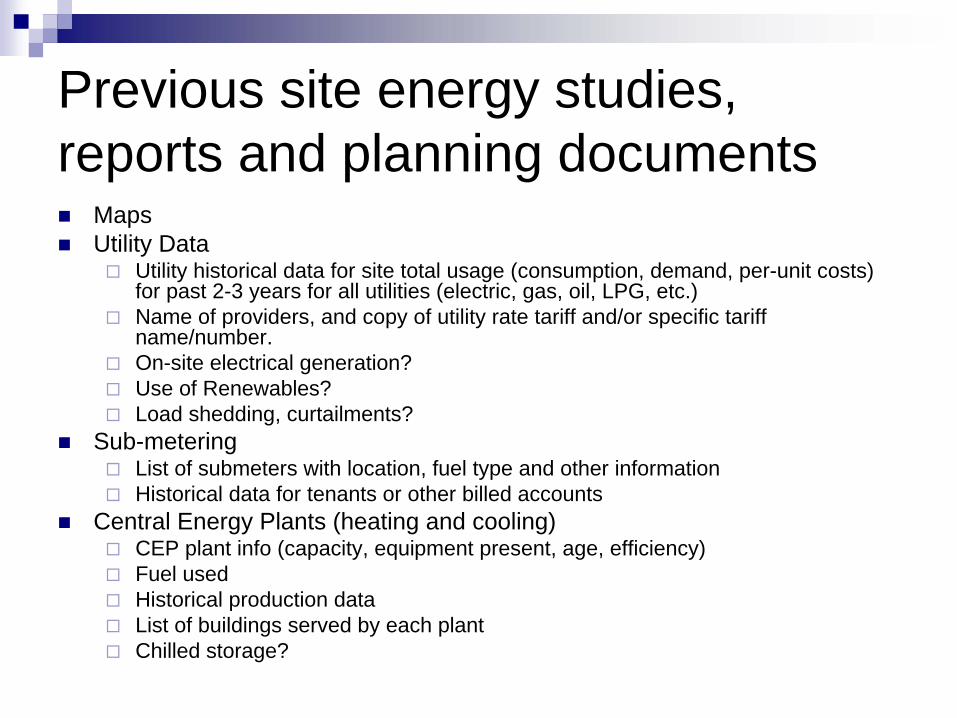
Previous site energy studies, reports and planning documents
MapsUtility Data
Utility historical data for site total usage (consumption, demand, per-unit costs) for past 2-3 years for all utilities (electric, gas, oil, LPG, etc.)Name of providers, and copy of utility rate tariff and/or specific tariff name/number. On-site electrical generation?Use of Renewables? Load shedding, curtailments?
Sub-meteringList of submeters with location, fuel type and other informationHistorical data for tenants or other billed accounts
Central Energy Plants (heating and cooling)CEP plant info (capacity, equipment present, age, efficiency)Fuel usedHistorical production dataList of buildings served by each plantChilled storage?
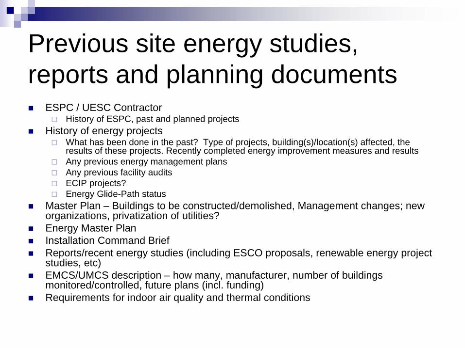
Previous site energy studies, reports and planning documents
ESPC / UESC ContractorHistory of ESPC, past and planned projects
History of energy projectsWhat has been done in the past? Type of projects, building(s)/location(s) affected, the results of these projects. Recently completed energy improvement measures and resultsAny previous energy management plansAny previous facility audits ECIP projects?Energy Glide-Path status
Master Plan – Buildings to be constructed/demolished, Management changes; neworganizations, privatization of utilities?Energy Master PlanInstallation Command BriefReports/recent energy studies (including ESCO proposals, renewable energy project studies, etc)EMCS/UMCS description – how many, manufacturer, number of buildings monitored/controlled, future plans (incl. funding)Requirements for indoor air quality and thermal conditions
Site Surveying ToolsLevel 1 Audit
ThermometersInfrared ImmersionWet bulb
Measuring tape or ultrasonic measurement deviceLight meterFlashlight, screw driverDigital camera
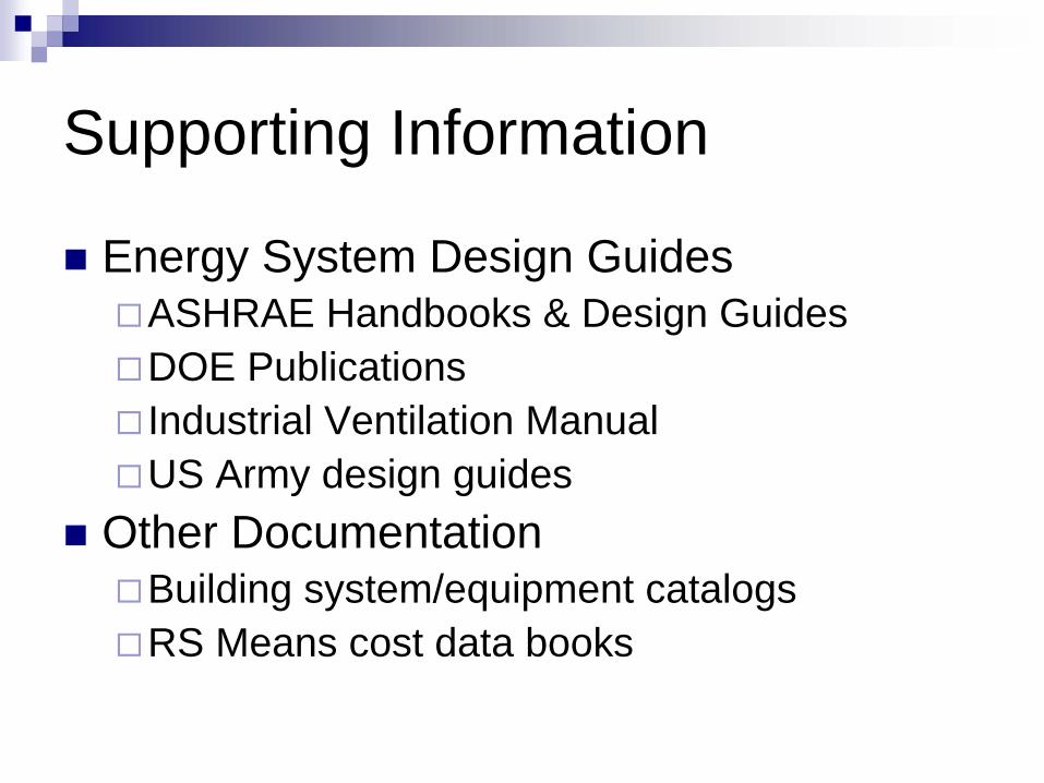
Supporting Information
Energy System Design GuidesASHRAE Handbooks & Design GuidesDOE Publications Industrial Ventilation ManualUS Army design guides
Other DocumentationBuilding system/equipment catalogsRS Means cost data books
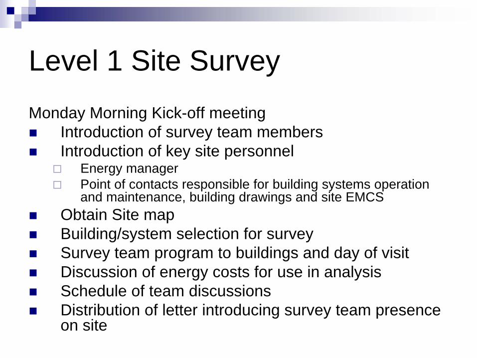
Level 1 Site SurveyMonday Morning Kick-off meeting
Introduction of survey team membersIntroduction of key site personnel
Energy managerPoint of contacts responsible for building systems operation and maintenance, building drawings and site EMCS
Obtain Site mapBuilding/system selection for survey Survey team program to buildings and day of visitDiscussion of energy costs for use in analysisSchedule of team discussionsDistribution of letter introducing survey team presence on site
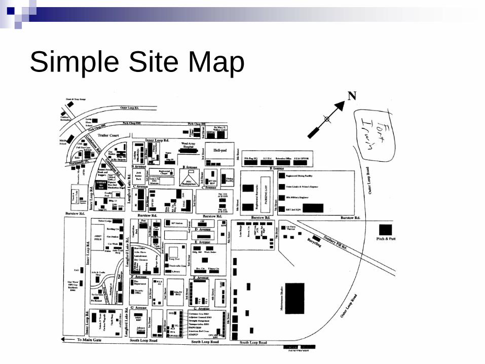
Simple Site Map
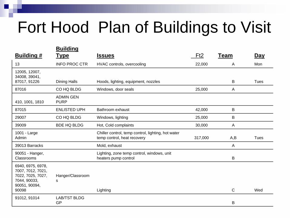
Fort Hood Plan of Buildings to Visit Building #
Building Type Issues Ft2 Team Day
13 INFO PROC CTR HVAC controls, overcooling 22,000 A Mon
12005, 12007, 34008, 39041, 87017, 91226 Dining Halls Hoods, lighting, equipment, nozzles B Tues
87016 CO HQ BLDG Windows, door seals 25,000 A
410, 1001, 1810ADMIN GEN PURP
87015 ENLISTED UPH Bathroom exhaust 42,000 B
29007 CO HQ BLDG Windows, lighting 25,000 B
39009 BDE HQ BLDG Hot, Cold complaints 30,000 A
1001 - Large Admin
Chiller control, temp control, lighting, hot water temp control, heat recovery 317,000 A,B Tues
39013 Barracks Mold, exhaust A
90051 - Hanger, Classrooms
Lighting, zone temp control, windows, unit heaters pump control B
6940, 6975, 6978, 7007, 7012, 7021, 7022, 7025, 7027, 7044, 90033, 90051, 90094, 90098
Hanger/Classroom s
Lighting C Wed
91012, 91014 LAB/TST BLDG GP B

Site Introduction Letter

Energy Cost Information
FuelsNatural gasFuel oilPropane
ElectricalUse costDemand costTime of day considerations

Level 1 – Building Surveys
Survey team looks for waste and/or inefficienciesExcessive space temperaturesExcessive outdoor ventilation airEquipment operating when not neededPoor building envelope – single pane windows, no insulation, lack of sealsLeaks in piping systems – internal & externalDisabled controls
Level 1 – Building Surveys
Information normally lackingBuilding energy useBuilding drawingsOperating schedulesMaintenance history
Survey team forms conclusions based on site observations interviews with building occupants and maintenance personnel, visits to EMCS control station and discussions with DPW staff.
Level 1 Team Interactions
Late afternoon summary of days findingsListing of ECM’sPreparation of slides for Friday debriefingReview of debriefing materialDebriefing presentationAssignment of ECM’s

Debriefing to Interested Personnel
DebriefingHeld Friday morningPowerPoint presentation by survey team of findingsDiscussion of findings generates feedback from site personnelPotential ECM’s identified
Used to select ECM authors

U.S. Army Corps
of EngineersEngineer Research and
Development Center
U.S. Army Corps
of EngineersEngineering and Support
Center, Huntsville
Fort Hamilton, NYApr 17, 2009
Energy Engineering Analysis Program (EEAP) Level I Energy Assessment Outbrief

Energy Assessment Team
HNCMark AllenTammie Learned
CERLJames Miller
Private contractorsAl Woody Curt BjorkJames Velthoven
PNNLAmy SolanaWill GorrissenMarcus De La RosaDaryl Brown
Fort HamiltonJoe GattoJackie RoebackJim JancarelliCraig SebaClarence Parker
What We Did
Reviewed and analyzed Fort Hamilton energy data, future construction plans and energy program documents. Reviewed existing facility building envelope and mechanical systems, “Mini Energy Plants”, and distribution systemsDeveloped potential energy conservation measure (ECM) ideas
Surveyed Facilities and SystemsFacilities (#)
Administration (111, 113, 114, 116, 117, 129, 137c, 301, 302)Barracks and Lodging (107, 209, 210)Dining (207)Education/Training (218, 219)Rec/Fitness/CDC (218, 402)Shops/Maintenance (127, 128)Miscellaneous (124, 125, 403)
SystemsHVACBuilding EnvelopeLighting (complete survey July 2009)Renewables (perform survey July 2009)

CERL Observations

HVAC – General ObservationsLocal temperature controls (including night setback) are functioningMaintenance people have awareness of deficiencies and have plans/strategies to correct – proactive and interested in improvementBldg 403 – Theater system NOT operating 24/7 (kudos!)Grass roofs are a “hot item” in the world of sustainability and Ft. Hamilton (Bldg 207) already has one – bragging rights!
HVAC – Specific ObservationsBldg 116
One air handling unit running with outside air and return air dampers closedNumerous air handling units running 24/7
Bldg 207 - Uninsulated piping and hot water storage tankBldg 402 – Gym possible candidate for radiant heating
Racquetball court - short circuit of supply / return air

Building Envelope – General
Window systems in most buildings are reasonably modern and energy efficientMost doors need weatherstripping added or replaced, door closers adjusted/replaced, etc.Roofing systems appear to be in good condition – no evidence of leakageWe noted many recently improved vestibules
Building Envelope – SpecificBldg 113 – Numerous issues:
Rotting wood, 1st floor doors and windowsSpalling and other masonry failuresAttic floor insulated, but attic heated and ventilated (“heating New York”). Under side of roof should be insulated.
Bldg 114 – Masonry issues, end of building and at building corner (apparent lintel deterioration)Bldg 124 – Existing rollup doors uninsulated and not weatherstrippedBldg 125 – Ceiling poorly insulatedBldg 128 – Large openings/gaps above rollup doors
Building Envelope – SpecificBldg 207 – Windows in Jackson Rm are single-glazed, aluminum frame. Some are structurally unsound and allowing water leakage to interior.Bldg 219 – Attic space above admin wing appears to be uninsulatedBldg 302 – First floor being renovated. Exterior walls appear to be uninsulated. Possible missed opportunity.Bldg 403 – Possible water entry at side exit door canopies causing deterioration of doors and door frames

CERL Initial Recommendations

Add Insulation to Heating Pipes & Hot Water Tank, Bldgs. 207, 111, 125, 128 and 129
Problem: In some Boiler Rooms pipes need insulation. A hot water tank is uninsulated in 207Solution: Add insulation to these hot pipes and tanks to reduce heat loss.
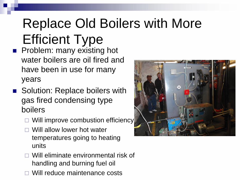
Replace Old Boilers with More Efficient TypeProblem: many existing hot water boilers are oil fired and have been in use for many yearsSolution: Replace boilers with gas fired condensing type boilers
Will improve combustion efficiencyWill allow lower hot water temperatures going to heating unitsWill eliminate environmental risk of handling and burning fuel oilWill reduce maintenance costs
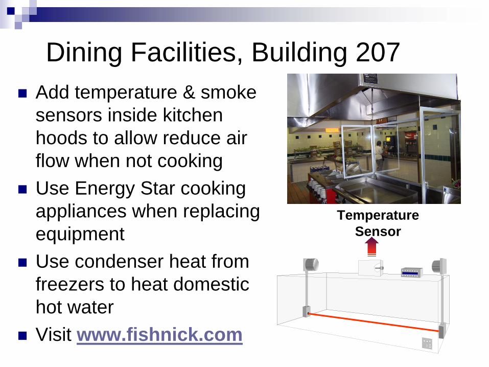
Dining Facilities, Building 207Add temperature & smoke sensors inside kitchen hoods to allow reduce air flow when not cookingUse Energy Star cooking appliances when replacing equipmentUse condenser heat from freezers to heat domestic hot waterVisit www.fishnick.com
Temperature Sensor

Install Gas Fired Domestic Hot Water Heater, Bldg. 137
Problem: Steam boilers must operate in summer to provide hot water to residents in 137A and 137B and occupants of 137CSolution: Install gas-fired domestic hot water heater
Takes steam load off central boiler plant in summer so you can turn off central boiler system
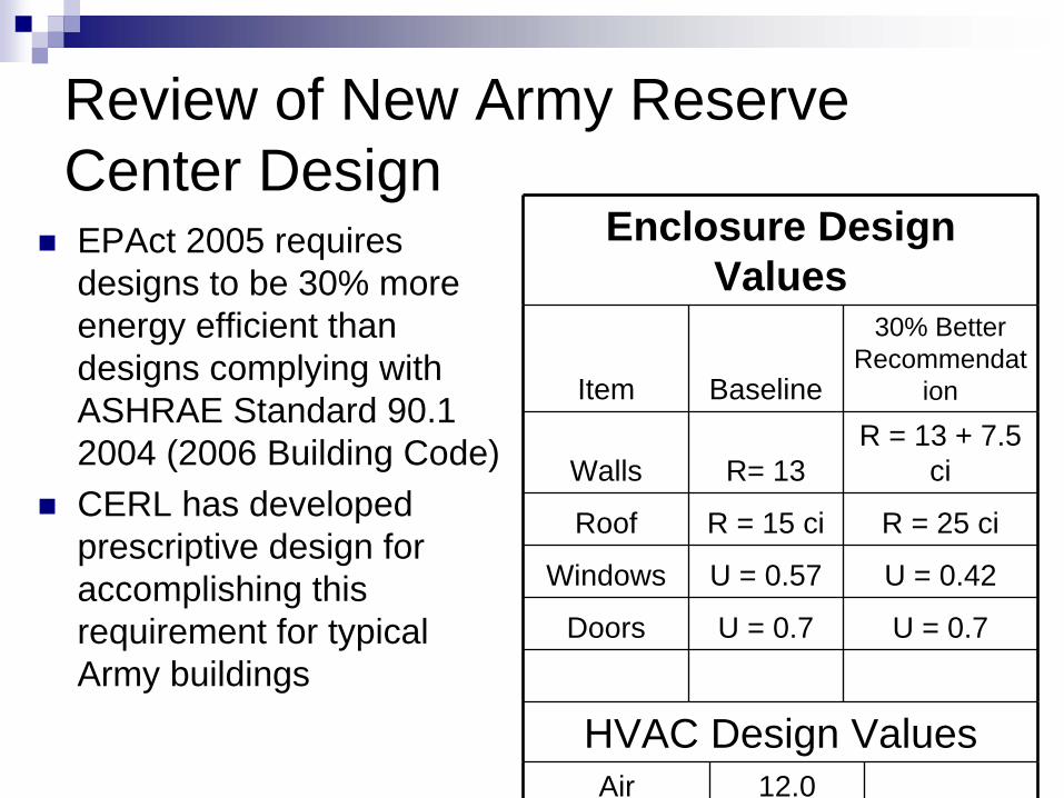
Review of New Army Reserve Center DesignEPAct 2005 requires designs to be 30% more energy efficient than designs complying with ASHRAE Standard 90.1 2004 (2006 Building Code)CERL has developed prescriptive design for accomplishing this requirement for typical Army buildings
Enclosure Design Values
Item Baseline
30% Better Recommendat
ion
Walls R= 13R = 13 + 7.5
ci
Roof R = 15 ci R = 25 ci
Windows U = 0.57 U = 0.42
Doors U = 0.7 U = 0.7
HVAC Design ValuesAir 12.0
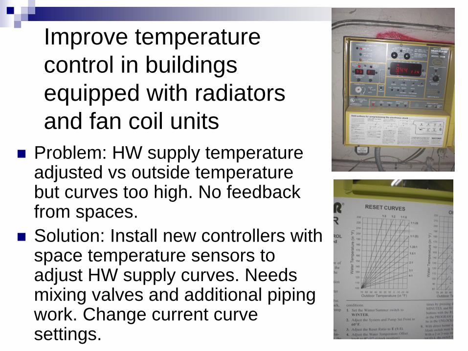
Improve temperature control in buildings equipped with radiators and fan coil units
Problem: HW supply temperature adjusted vs outside temperature but curves too high. No feedback from spaces.Solution: Install new controllers with space temperature sensors to adjust HW supply curves. Needs mixing valves and additional piping work. Change current curve settings.
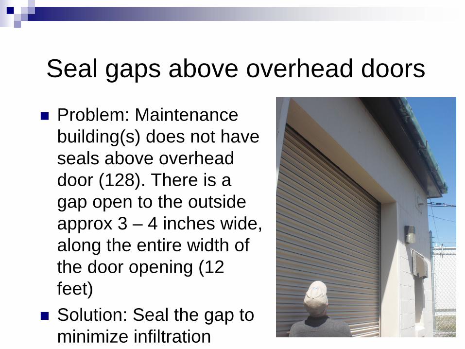
Seal gaps above overhead doors
Problem: Maintenance building(s) does not have seals above overhead door (128). There is a gap open to the outside approx 3 – 4 inches wide, along the entire width of the door opening (12 feet)Solution: Seal the gap to minimize infiltration
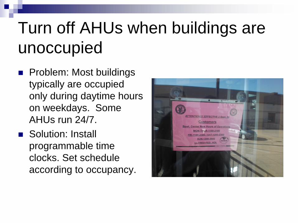
Turn off AHUs when buildings are unoccupied
Problem: Most buildings typically are occupied only during daytime hours on weekdays. Some AHUs run 24/7.Solution: Install programmable time clocks. Set schedule according to occupancy.
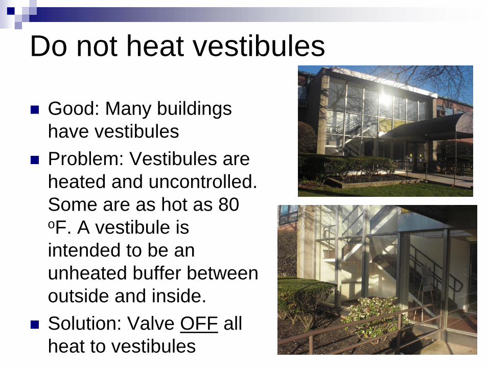
Do not heat vestibules
Good: Many buildings have vestibulesProblem: Vestibules are heated and uncontrolled. Some are as hot as 80 oF. A vestibule is intended to be an unheated buffer between outside and inside. Solution: Valve OFF all heat to vestibules

Lighting
Most has been changed to T8s and CFLsSome T12s and incandescents remainingOccupancy controls needed, especially in storage areas, boxing room in gym, and other low-use areasSome exterior lighting needs photocells replacedDecouple lights from ventilation fans in boiler room of Club

PNNL Observations & Recommendations
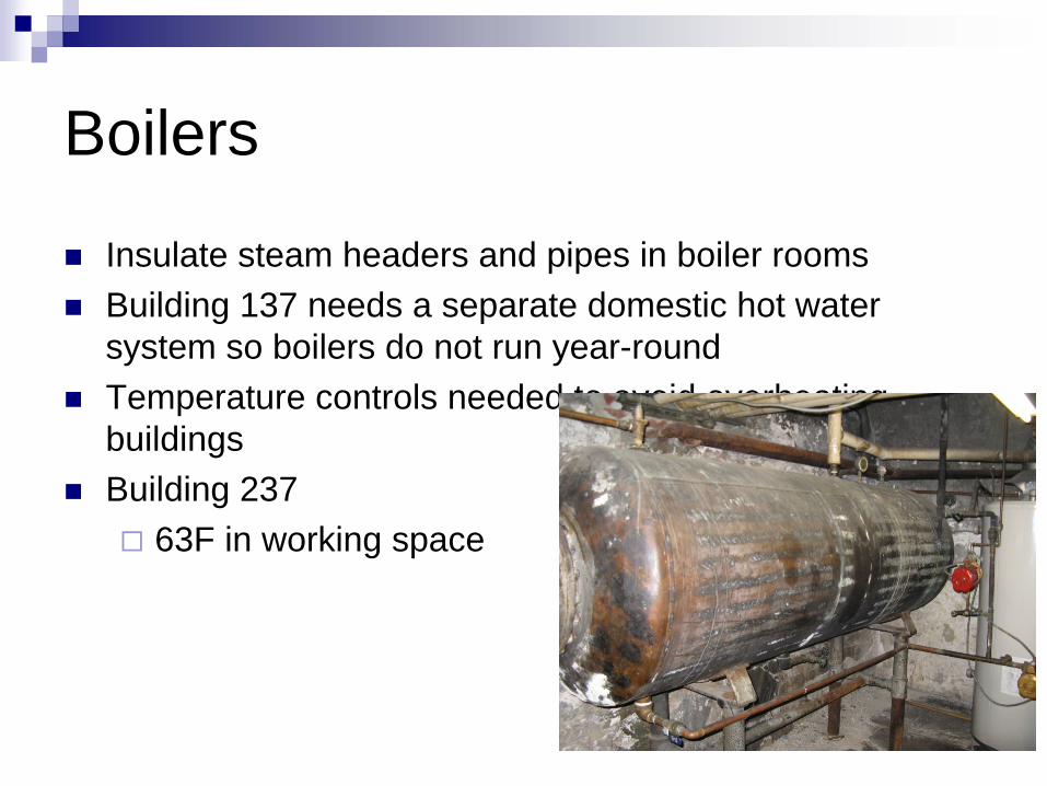
Boilers
Insulate steam headers and pipes in boiler roomsBuilding 137 needs a separate domestic hot water system so boilers do not run year-roundTemperature controls needed to avoid overheating buildingsBuilding 237
63F in working space
Envelope
Windows have been mostly replaced with double-pane windows, but they need weatherstrippingInsulation needed in chapel ceilingSome windows and doors do not close all the wayInstall drop ceiling with insulation in buildings 124 and 125
What’s Next?
Summary of Level I ResultsTechnical Report of Level I ReportLevel II Analysis?Development of actual projectsImplementation of projects (assistance with funding issues)

Acquisition StrategyLow cost ECMs
Operational changes (e.g., stop heating vestibules)Small SRM-funded projects
Minimal or reasonable cost ECMsSRM-funded projectsECIP
Big $ ECMsECIPCentrally funded3rd party financed (UESC, ESPC, EUL, etc.)MCA

Questions or Comments ?Contact Information
Mark Allen (256) 895 - 1724James Miller (217) 373 - 4566Amy Solana (503) 417 - 7568
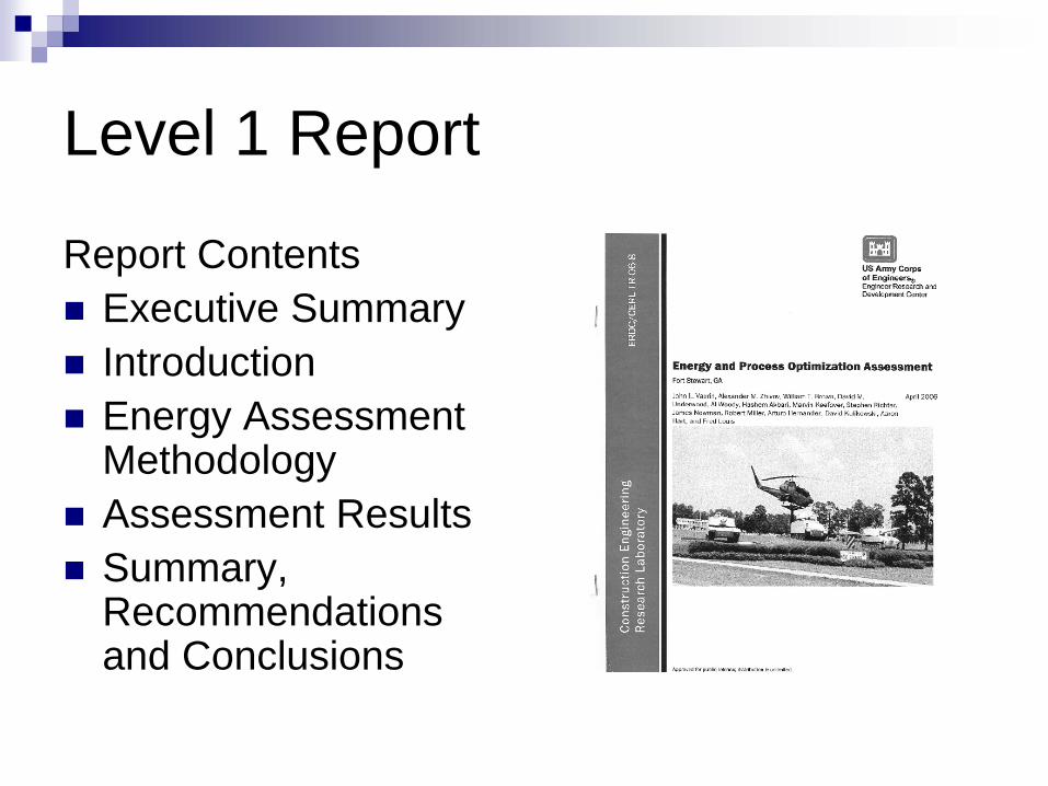
Level 1 Report
Report ContentsExecutive SummaryIntroductionEnergy Assessment Methodology Assessment ResultsSummary, Recommendations and Conclusions
Level 1 ECM Write-ups
Presentation of identified ECM’s Existing conditionsSolutionSavingsCostPayback

Sample ECM Write-upHVAC XX Control Kitchen Hood’s Air Flow in
Club, Building 207Existing Condition:
In the Club Building there are two kitchen hoods that would benefit by the installation of air flow controls. Both typically operate through out the working hours of the kitchen. These hoods continue to exhaust air even though there is no cooking occurring under them. Thus the hoods operate when they don’t need to operate and energy is wasted. This dining facility operates 62 hours per week. It is closed on Mondays. Cooking is estimated to be going on under the hoods for approximately 75% of the time leaving about 2.6 hours per day a reduced hood air flow could be taken.
Solution:Sensors can be placed on the exhaust system that will vary the air flow from full flow down to half flow. An optic sensor in the hood will monitor the presence of smoke and cooking vapors. A temperature sensor placed in the duct attached to the hood will note an increase in temperature. The start of cooking activities under the hood will provide a positive indication by either of these sensors and the exhaust air flow will be increased to full flow.
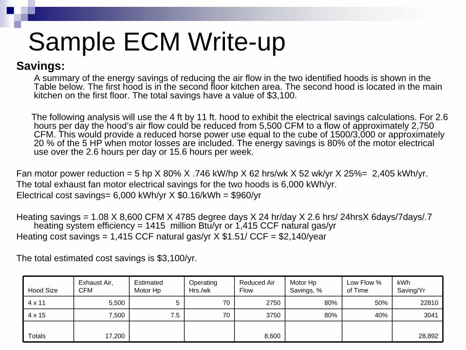
Sample ECM Write-upSavings:
A summary of the energy savings of reducing the air flow in the two identified hoods is shown in the Table below. The first hood is in the second floor kitchen area. The second hood is located in the main kitchen on the first floor. The total savings have a value of $3,100.
The following analysis will use the 4 ft by 11 ft. hood to exhibit the electrical savings calculations. For 2.6 hours per day the hood’s air flow could be reduced from 5,500 CFM to a flow of approximately 2,750 CFM. This would provide a reduced horse power use equal to the cube of 1500/3,000 or approximately 20 % of the 5 HP when motor losses are included. The energy savings is 80% of the motor electrical use over the 2.6 hours per day or 15.6 hours per week.
Fan motor power reduction = 5 hp X 80% X .746 kW/hp X 62 hrs/wk X 52 wk/yr X 25%= 2,405 kWh/yr.The total exhaust fan motor electrical savings for the two hoods is 6,000 kWh/yr.Electrical cost savings= 6,000 kWh/yr X $0.16/kWh = $960/yr
Heating savings = 1.08 X 8,600 CFM X 4785 degree days X 24 hr/day X 2.6 hrs/ 24hrsX 6days/7days/.7 heating system efficiency = 1415 million Btu/yr or 1,415 CCF natural gas/yr
Heating cost savings = 1,415 CCF natural gas/yr X $1.51/ CCF = $2,140/year
The total estimated cost savings is $3,100/yr.
Hood SizeExhaust Air, CFM
Estimated Motor Hp
Operating Hrs./wk
Reduced Air Flow
Motor Hp Savings, %
Low Flow % of Time
kWh Saving/Yr
4 x 11 5,500 5 70 2750 80% 50% 22810
4 x 15 7,500 7.5 70 3750 80% 40% 3041
Totals 17,200 8,600 28,892
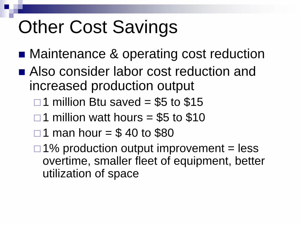
Other Cost SavingsMaintenance & operating cost reductionAlso consider labor cost reduction and increased production output
1 million Btu saved = $5 to $151 million watt hours = $5 to $101 man hour = $ 40 to $80 1% production output improvement = less overtime, smaller fleet of equipment, better utilization of space
Sample ECM Write-up
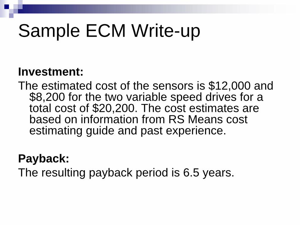
Investment:The estimated cost of the sensors is $12,000 and
$8,200 for the two variable speed drives for a total cost of $20,200. The cost estimates are based on information from RS Means cost estimating guide and past experience.
Payback:The resulting payback period is 6.5 years.

Follow-up to Level 1 Survey
Meeting at site to discuss resultsDiscussion of further involvement and potential Level 2 activitySupport for ECIP documentation
Level 2 Survey
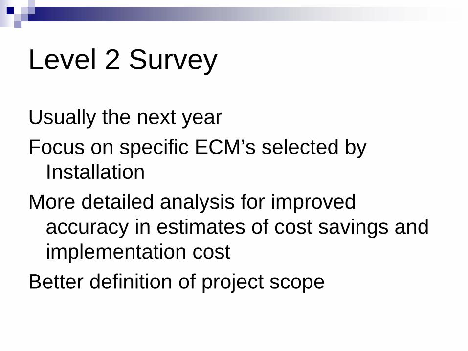
Usually the next yearFocus on specific ECM’s selected by
InstallationMore detailed analysis for improved
accuracy in estimates of cost savings and implementation cost
Better definition of project scope
Level 2 Audits
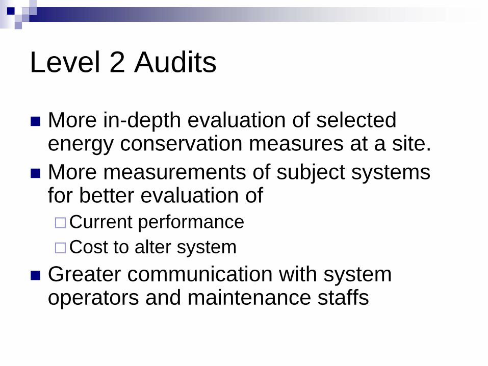
More in-depth evaluation of selected energy conservation measures at a site.More measurements of subject systems for better evaluation of
Current performanceCost to alter system
Greater communication with system operators and maintenance staffs
Level 2 Audits - Planning
Selection of Items for evaluationSelected by installationNormally complicated projects that offer significant savingsMore information required to prove feasibility, substantiate savings and/or generate accurate cost to installInformation provided includes documentation of savings, component selection and project scope

Level 2 Audits - Planning
Team selectionBased on selected projectsNormally 4 – 5 team membersVisit 1 – 2 weeks long
Coordination with Site personnelSite access informationIntroductory letterDocumentation on subject buildings/systems
Level 2 Audit Site Surveying Tools
Temperature sensing devicesDistance measurement toolsLight metersElectrical volt, ohm, amp meterAir flow measurement equipmentCombustion test kitVibration sensorNoise meterInfrared thermography cameraBlower-door

Level 2 Audit – Site Visit
System/Building evaluationExisting System performance measurementsIdentification of existing conditions & design of system modifications related to improvementDiscussions with Site personnel regarding identified problem and proposed solution
Is problem real?Is proposed solution valid?
Level 2 Audit – Site Briefing
Review of findingsDocumentation of current energy useDiscussion of proposed solution
Potential equipment suppliersOperation issuesMaintenance requirementsUnusual cost that may be experienced
Level 2 Audit – Report
Complete system analysis defining energy use and other cost issuesDetailed cost estimate of savings and implementation costRecommendation of design approach, possible suppliers and implementation schedule
ECM Implementation Cost
Engineer the desired change Identify needed components - type and sizeVision how they would be installedDetermine length and distances for pipe, ducts, etc.
Use equipment venders and estimating references (R. S. Means) to determine costAdd some contingency cost for difficulty to implement, poor access and project unknowns.
Determine ECM Economics Determine payback period for initial screeningUse Life Cycle Cost analysis to prioritize project
20 – 25 year life Use present worth factors and projected fuel price indices provided in the annual supplement to NIST Handbook 135 to determine total life cost of changeFor a detailed explanation of the principles of life-cycle cost (LCC) analysis, please request Handbook 135, Life-Cycle Costing Manual for the Federal Energy Management Program, Available FEMP's web site at www.eere.energy.gov/femp/information/download_blcc.cfm.A computer program is downloadable from FEMP's web site at www.eere.energy.gov/femp/information/download_blcc.cfm.

Report
Executive SummaryIntroductionEnergy Assessment methodologyEnergy and Process Optimization Assessment at Ft. XXFt XX Assessment ResultsConclusions and Recommendations
Ft XX Assessment Results
ECM Write-up – provide language for 1391 submissionExisting Conditions
Current situationRequirement
SolutionProject description or desired changeImpact if not provided
SavingsInvestmentPayback
Level 3 Audits
For a specific ECMsProvide Conceptual Design
Description of necessary workSketchesListing of componentsEquipment specificationsCatalog cutsSequence of operation
Level 3 Audits
Support during detailed design and constructionEvaluation of operating system
CommissioningEnergy savings measurementConfirmation of successful solution
Net Zero Energy Use
No fossil fuel use by 2030 (Energy Independence & Security Act 2007)Building energy and plug in energy useRequires very efficient building and systems plus use of renewable energy sources.

Problem with Plug/Process Loads
Barracks – Plug loads more than half of electrical use after building optimized
153,000 kWh/yr out of 278,000 kWh/yrDining facility – Cooking, food handling and washing equipment account for more than half energy use after building optimized
1247 million Btu/yr out of 2132 million Btu/yr

Renewable Energy Sources
Solar Hot Water collectorsGround source heat pumpsWind energyPhotovoltaic solar collectorsBurning biomassSolar WallsHydro power generation

Thank You
Questions?