Lessons Learned – Marine Operations in The Minas Passage
52
LESSONS LEARNED Marine Operations Minas Passage
Transcript of Lessons Learned – Marine Operations in The Minas Passage

LESSONS LEARNED
Marine Operations Minas Passage
Lessons Learned – Marine Operations in The Minas Passage
2
Contents How to Use This Report
Introduction
Acronyms and Abbreviations
Types of Vessels
Dive Operations
Equipment
Challenges
Environmental limitations
Fundy Advanced System Technology (FAST)
Vendors
Appendix 1: Vessel Information
Appendix 2: FAST Reports
Appendix 3: Diving
Appendix 4: Station Keeping / Mooring Trials
Appendix 5: Video
How to Use This Report
The report describes the marine service resources available for sea-going operations in the Bay
of Fundy, including their operational advantages and limitations. It also describes the
operational constraints of this complex, high energy marine environment and provides
information to help address commonly encountered situations. The report provides contact
information of the many vendors and service providers available to support marine operations
in the Bay of Fundy. For additional information or more detail on the work described herein,
please contact Jason Clarkson at Operational Excellence Consulting Inc or Andrew Lowery at
the Fundy Ocean Centre for Research (FORCE) at.

Lessons Learned – Marine Operations in The Minas Passage
3
Introduction
Fundy Ocean Research for Energy (FORCE), Offshore Energy Research Association (OERA) and
Operational Excellence Consulting Inc. have teamed up to capture lessons learned from marine
operations in the Minas Passage. The project involves information that is shared from developers
and contractors who have been performing marine operations in the past number of years. The
purpose is to help the tidal industry in Nova Scotia by sharing information about operations and
experiences while operating in the conditions that are unique to the Minas Passage.
The report includes a detailed overview of the resources used while performing marine activities
in the Minas Passage such as:
1. Types of Vessels
2. Types of equipment
3. Diving Operations
4. Challenges
5. Environmental limitations
6. Environmental Monitoring Equipment
7. Instrumentation Technology (SONAR etc.)
8. Vendors

Lessons Learned – Marine Operations in The Minas Passage
4
Acronyms and Abbreviations
ADCP = Acoustic Doppler Current Profiler
ASD = Azimuth Stern Drive
ATL = Atlantic Towing Limited
BP = Bollard Pull
CLA = Crown Lease Area
DGPS = Differential Global Positioning Systems
DP(S) = Dynamic Positioning (System)
EMS = Environmental Management System
FAST = Fundy Advanced Sensor Technology
FORCE = Fundy Ocean Research for Energy
FRM – Float Release Mechanism
HP = Horse Power
Kts = Knots
Lbs = Pounds
MBR = Maximum Bend Radius
MW = Mega Watt
PPE = Personal Protective Equipment
RHIB = Rigid Hull Inflatable Boat
ROV = Remote Operated Vehicles
t = tonnes
VHF = Very High Frequency

Lessons Learned – Marine Operations in The Minas Passage
5
Types of Vessels
The following vessels are used during various marine operations in the Minas Passage:
Scotia Tide:
OpenHydro’s Lifting barge to deploy and recover turbines. Built in Pictou, Nova Scotia
and launched in 2015 the Scotia Tide is a purpose-built installation barge for the 2MW
(Mega Watt) turbines installed for Cape Sharp Tidal. Capable of lifting and lowering the
1000+ T (tons) turbine to and from the seabed. The vessel is not powered and needs to
be towed to transport and install the turbines.
Barge Specifications:
Length: 64 Meters Width: 38 Meters Draft Empty: 5 .8 Meters
Capacity: 1150 T Keel Laid: 2015 Draft Loaded: 9.0 Meters
Design: Catamaran

Lessons Learned – Marine Operations in The Minas Passage
6
Atlantic Towing Ltd Anchor Handling Tug Supply Vessel (AHTS) (see datasheet in
Appendix 1):
Two vessels of this type have been previously used for operations in the Minas Passage.
The Atlantic Kingfisher and the Atlantic Osprey have 176.4t continuous bollard pull
capability were used on different occasions in the Minas Passage by developer
OpenHydro. A performance rating on this vessel including the limitations and it role in
the operations are outlined by the developer below.
o Scope of Work: Towing of Scotia Tide, Position of Scotia Tide in berth for turbine
deployment.
Performance: Performed well. A high bollard pull is required due to the high
drag of the turbine. At some point we did reach 100% of the engine thrust
when deploying turbine (without consequences). We are reviewing our
method statements to avoid this in the future. We have analyzed the data
from the last deployment, we have lowered the window threshold, based
on recorded data and calculations, and this will reduce the required BP
and limit power.
Limitations: Effective bollard pull, is now a known factor, this was not fully
understood prior to the last deployment; this ultimately feeds back to the
design of the operations, especially in terms of timings.
o Remarks: Captain’s experience is the key in all operations.
“We are requesting Atlantic Towing to provide the same captain that
performed turbine deployment in 2016 for the next deployment.” - Julien LeClerc
– Naval Energies.

Lessons Learned – Marine Operations in The Minas Passage
7
Atlantic Towing Ltd harbour Azimuth Stern Drive (ASD) tugs (see datasheets in Appendix
1):
Atlantic Towing Ltd has a fleet of ASD tugs typically used for ship assist in ports as well as
various other towing and marine operations. A number of these ASD tugs have been
used for operations in the Minas Passage. A performance rating on this vessel type
including the limitations and its role in the operations are outlined by the tidal turbine
developer OpenHydro and are outlined below.
Atlantic Fir:
o Scope of Work: Towing of Scotia Tide during turbine recovery and Motoring trials.
Performance: Performed well. 63 tons bollard pull, most powerful ASD tug to
tow the Scotia Tide. It performed extremely well during the turbine recovery
operation, very impressive position keeping throughout; these can only be
used for a recovery operation they must start with low drag.
Limitations: Bollard pull: Note the ASD’s seem to have better effective
bollard pull than other propulsion types. Again, operations are always
designed around bollard pull.
o Remarks: Captain’s experience is the key here. OpenHydro would request ATL to
provide the same captain that already performed turbine recovery or cable
operations for the next coming operations.

Lessons Learned – Marine Operations in The Minas Passage
8
Atlantic Hemlock:
o Scope of Work: Stern tug holding turbine tail during turbine deployment, Forward
tug towing the Beaver barge during cable operations.
Performance: Performed Well. Fitted with bow winch to hook up onto a
mooring and tow Irving Beaver barge at the same time. The Atlantic
Hemlock is the most versatile ASD and one of the best performing in their
fleet, also used for tail handling.
Limitations: Bollard pull. Not able to tow Scotia Tide for recovery or
deployment operations, but acceptable for lesser operations such as
motoring trials or such.
o Remarks: Captain’s experience is the key here.
“We are requesting Atlantic Towing to provide the same captain that already
performed cable operations in 2016 for the next coming operations.” – Julien
LeClerc – Naval Energies.

Lessons Learned – Marine Operations in The Minas Passage
9
Atlantic Bear:
o Scope of Work: Stern tug for Irving Beaver barge, pushing the barge while towed
by Atlantic Hemlock. Positioning/stabilizing the Irving Beaver barge on berth D.
Performance: Performed well. Fitted with bow winch, useful for high
capacity winch on Irving Beaver barge for cable operations. Very powerful
ASD with 70t BP, but the Atlantic Bear’s exceptional performance is largely
attributed to its Captain Joey Mayalls.
Limitations: Cannot tow the Beaver barge. No stern winch.
o Remarks: Captain’s experience is the key here.
“We are requesting ATL to provide the same captain that already performed
cable operations for the next coming operations.” – Julien LeClerc – Naval Energies.

Lessons Learned – Marine Operations in The Minas Passage
10
Irving Beaver barge (see datasheet attached):
The Irving Beaver is a flat deck unmanned barge operated by Atlantic Towing Ltd. A
performance rating on this vessel type including the limitations and it role in the
operations are outlined below by the tidal turbine developer OpenHydro.
o Scope of Work: Turbine connection, mooring installation.
Limitations: A large barge difficult to control with ASD tugs in high currents
during cable operations.
o Remarks: A smaller barge must be investigated for better control with positioning
on site. In addition, using a cargo barge such as the Irving Beaver barge requires
the use of two tugs, one lead tug for towing and a stern tug to control the barge
in strong current. The operation also requires the mobilization of a crane, winches,
chutes, containers/control rooms, survey system, and other required equipment to
be ready for cable operations. As consequence, mobilization/demobilization
costs and vessels & equipment daily rates makes cable operations very expensive.
” The ideal case would be to mobilize a large mutilcat (already fitted with
cranes and winches) suitable for our operations (see specification in Appendix
1). It would lower our operational costs drastically. But such vessel (popular in
Europe) is not available in North America.”- Julien LeClerc – Naval Energies.

Lessons Learned – Marine Operations in The Minas Passage
11
Nova Endeavour (assistance vessel from Huntley Sub-Aqua Construction):
Huntley’s Sub Aqua Construction is a vessel operator and commercial construction diving
company used by developers and other operators in the Minas Passage. It operates two
vessels the Nova Endeavor and a self-propelled barge called the KIPAWO. A performance
rating on the Nova Endeavor including the limitations and it role in the operations are
outlined by the tidal turbine developer OpenHydro and are outlined below.
o Scope of Work: Assistance vessel used for line recovery and transfer to other
vessels, survey operations, grappling ops, diving ops, inspection and maintenance
of recovery line, safety boat during operations.
Performance: Performed well. Very versatile and useful tool on the water.
The crew has good experienced and come highly recommended.
Limitations: Limited safe working load on A-frame/winch, cannot be used
for heavy duty works,
o Remarks: The Nova Endeavor is a work boat capable of deployment of FORCE’s
instrumentation FAST platforms and other monitoring equipment. This vessel has
also been involved in every marine operation including the deployment and
recovery oper of the Cape Sharp Turbine since 2015.

Lessons Learned – Marine Operations in The Minas Passage
12
Lessons Learned – Marine Operations in The Minas Passage
13
Tidal Runner (crew boat from RMI Marine):
RMI Marine is a vessel operator and professional dive company that has operated crew
transfer and safety vessel services as well as platform installations in the Minas Passage
with various companies including tidal turbine developers and instrument operators. One
of the most commonly used vessels in the Minas Passage is the Tidal Runner. With a recent
upgrade the this landing style craft with twin 300 horse power Yamaha outboard engines
and mountable A-Frame provides a variety of options.
o Scope of Work: Transfer of personnel (crew boat), safety boat during
operations, assistance on site with pick-up lines.
Performance: Performed well for crew transfer and as a safety boat.
Difficult to manage pick-up lines/buoys in berth D prior to upgrades being
completed.
Limitations: Vessel is difficult to control/maneuver in high speed currents on
berth D. Too difficult for Tidal Runner to pick-up a recovery line on Berth D
as the vessel can lose control in high currents while pulling on a recovery
line. I would like to note that this issue has been resolved with the addition
of two new 300HP Yamaha outboard engines now installed on the Tidal
Runner. Performance improved immensely, and maneuverability is no
longer a concern.
o Remarks: “Looking back, we would suggest a minimum cruising speed of at least
20 knots, fully loaded. We took this very seriously and therefore repowered our Tidal
Runner with twin 300 HP Yamaha outboards which cruise comfortably at 25 Knots.”
- Mike Gregg RMI Marine

Lessons Learned – Marine Operations in The Minas Passage
14
Dive Operations
RMI Marine has made several successful dives in the Minas Passage. Diving in the Minas is
achievable when certain conditions are met, and good planning is employed.
o Scope of Dives:
Dive 1 – RMI divers were tasked to assist FORCE with the recovery of a sensor
platform deployed in the Minas Passage. Dive video can be found in Appendix 3
Dive 2 – OpenHydro tasked RMI with performing several dives on the 16m diameter
turbine located in berth d in the Crown Lease Area (CLA) in the Minas Passage.
o Challenges:
The main concerns are tides, visibility, entanglement, and diver injury all of which can be
safely controlled by good procedures and planning. A stable dive platform such as a
barge or vessel is required and needs to be safely held in position. It should also have good
egress means. Surface supplied diving gear should be the only equipment used as it can
provide communications, rescue, and diver control. With surface supplied diving
equipment an umbilical is attached to the top hat of the diver which allows constant
communication with the diver while supply air to the diver during the dive.
“Looking back at some of the challenges, equipment redundancy is important
as there are very limited resources in the immediate area.” Mike Gregg – RMI
Marine
A dive operator should be prepared to carry spare equipment and to make
necessary repairs and should seek out local expertise and resources in the event of
a break down.
Medical emergencies are always a factor so when the projects are greater in
magnitude, so should be the availability of medical response. This may entail the
need for a second standby safety vessel.

Lessons Learned – Marine Operations in The Minas Passage
15
Operating small vessels outside daylight hours presents risk of entanglement with
fishing gear and collision with large floating debris which is always present,
particularly during extreme tides. Small vessels are equipped with radar, but some
low-profile floating objects cannot be detected when it is dark.
Communications on the water are crucial. Any vessel involved in tidal operations
should have at least two working VHF radios monitoring dedicated working
channels. Cell phone coverage is not always reliable, and operators should limit the
use of such unless prescribed.
o Limitations:
Due to the short durations to which diving can be performed, all diving operations
should be kept within the no decompression limits. In reference to “short durations”
we have experienced a safe dive window of approximately 20 minutes and possibly
extending this by 5 – 10 minutes depending on the diver’s comfort. The rapidity at
which the tide turns is influenced by the moon phase, so the tide turn can be as brief
as 15 minutes and as much as 30 minutes. The diver has to be deployed at least 15
minutes before the scheduled low tide turn and his recovery is dependent on when
the tide gains to much force going the other way.
“The diver’s recovery is paramount, so the diving window should be closely
monitored. Bottom time is measured from the time the diver leaves the surface until
the time the diver leaves the bottom. The diver’s recovery time is not factored in, but
his ascent rate should not exceed 60 feet/min. We use the DCIEM Diving Manual,
January 1995, particularly Table 1: Standard Air Decompression (feet). As per Table
1 using a depth of 100 feet as an example, the diver would have 15 minutes of
bottom time without having to do any decompression, i.e. in water decompression
or recompression chamber. “Mike Gregg – RMI Marine.
Lessons Learned – Marine Operations in The Minas Passage
16
For all operations, a diving contractor should provide an approved recompression
chamber and support equipment.
A comprehensive safe diving plan complete with emergency arrangements and
contingencies is mandatory and should be developed to include all parties but
should not be so complex that it limits the intended scope of work.
The diving operations conducted by RMI Marine pertaining specifically to the tidal
projects involved input from several parties, so a diving contractor should expect to
expend considerable resources in the development of an approved dive plan.
o Key Lessons:
A stable dive platform such as a barge or vessel that can be held on station in
minimal currents is required.
Surface supplied diving equipment complete with communications and lighting is
required. (Note: Surface-supplied diving is diving using equipment supplied with
breathing gas using a diver's umbilical from the surface, either from the shore or from
a platform such as a barge or diving support vessel.)
A solid dive safety plan is mandatory as is an experienced dive team.
Diving depths should be verified, and bottom times should be conservative to avoid
in water decompression.
The dive objective should be understood by all onboard to achieve success.
Through experience it was determined that a diver could be safely deployed at
least one-half hour before the scheduled low tide and successfully dive for
approximately 20 minutes. Even if there was an indication of surface flow, the
bottom flow had already slackened.

Lessons Learned – Marine Operations in The Minas Passage
17
Diving should be conducted only at the low slack tide as the current flow changes
too quickly at the high slack tide.
Visibility is an issue so diving, if required, should be conducted at the appropriate
daylight low tides. Good lighting on the diver’s helmet is essential.
Potential entanglement is always an issue, a good diver’s knife, a standby diver, and
a solid emergency plan with suitable rigging & deck equipment for emergency use
is mandatory.
Lessons Learned – Marine Operations in The Minas Passage
18
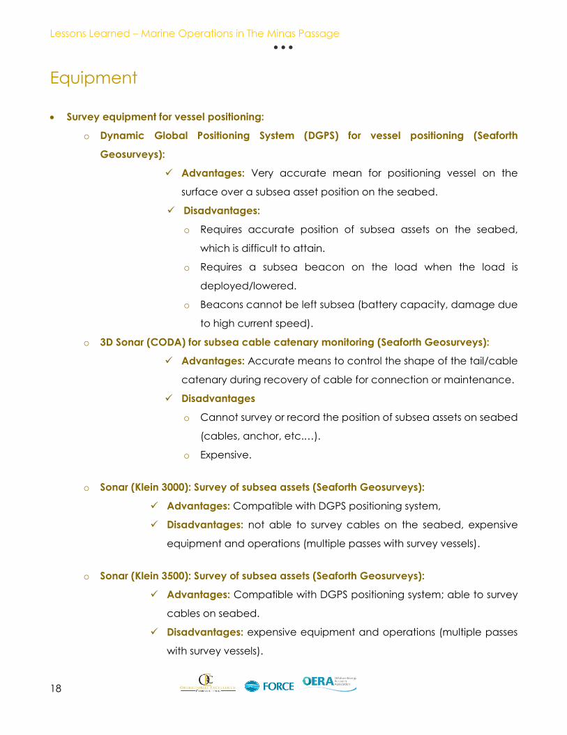
Equipment
Survey equipment for vessel positioning:
o Dynamic Global Positioning System (DGPS) for vessel positioning (Seaforth
Geosurveys):
Advantages: Very accurate mean for positioning vessel on the
surface over a subsea asset position on the seabed.
Disadvantages:
o Requires accurate position of subsea assets on the seabed,
which is difficult to attain.
o Requires a subsea beacon on the load when the load is
deployed/lowered.
o Beacons cannot be left subsea (battery capacity, damage due
to high current speed).
o 3D Sonar (CODA) for subsea cable catenary monitoring (Seaforth Geosurveys):
Advantages: Accurate means to control the shape of the tail/cable
catenary during recovery of cable for connection or maintenance.
Disadvantages
o Cannot survey or record the position of subsea assets on seabed
(cables, anchor, etc.…).
o Expensive.
o Sonar (Klein 3000): Survey of subsea assets (Seaforth Geosurveys):
Advantages: Compatible with DGPS positioning system,
Disadvantages: not able to survey cables on the seabed, expensive
equipment and operations (multiple passes with survey vessels).
o Sonar (Klein 3500): Survey of subsea assets (Seaforth Geosurveys):
Advantages: Compatible with DGPS positioning system; able to survey
cables on seabed.
Disadvantages: expensive equipment and operations (multiple passes
with survey vessels).
Lessons Learned – Marine Operations in The Minas Passage
19
Work class Remotely Operated Vehicle (ROV) for subsea surveys (Oceaneering):
Advantages: Provides video footage and has the ability to move subsea
to survey specific locations on seabed.
Disadvantages: Difficult to deploy and recover in high current speeds
(<.1.5 knots), very limited operational time subsea to perform survey (a
total water time of approximately 2 hours 10 minutes), very difficult to
control underwater with currents, not recommended for any subsea
intervention in the berth D area. This would include surveys, mechanical
work, free lines from entanglement, etc. Very expensive tool (high day
rates for ROV + ROV support vessel). ROV footage from the Minas
Passage can be found in Appendix 4.
Crawler Cranes:
An LR1400 440 (t) Crawler crane was used onboard the Irving Beaver Barge. Various other
crawler cranes have been used during operations in the Minas Passage for a variety of
operations. The LR1400 440 (t) crawler was used for the Open Hydro turbine connection
operation. An important thing to consider when selecting a crane is the derating of the
cranes capacity when used on the deck of a barge.
For example; Irving Equipment Limited will only utilize a crane make & model that has
been approved for use on a barge from the manufacturer. In this case, the manufacturer
will provide a set of “Barge Charts” that will contain lift capacities for varying degrees of
list, usually from 0 to 2 degrees.
“We always plan for the worst case and use the 2 degree-list charts. Barge chart
capacities will be lower than a standard set of capacity charts, which is done
not only to help account for barge list, but also the dynamic forces created
from wave action or other barge movements.” – Ryan Long Branch Manager
Irving Equipment Limited

Lessons Learned – Marine Operations in The Minas Passage
20
In the case of the LR1400 that was used on the Irving Beaver, the crane had a gross
capacity of 102,238lbs using the 2-degree barge charts. In the exact same configuration
on land, the standard charts indicate that it would have 126,000lbs capacity.
Winches:
10 (t) air powered winches, performed well, but slow pay-in speed. A slow pay-in speed
will increase the time it takes for the winch to retrieve something that has been attached
to it and lead to longer operational times in a tidal a tidal window. These were used
onboard the Irving Beaver during multiple operations and were supplied by Oceanside
Equipment in Halifax.
Over Boarding Chutes:
Customs built and designed for use with the Irving Beaver arrangement, they reportedly
performed well. The chutes were designed for high currents, but required considerable
welding work required to install them on the barge which was expensive.
Quadrant:
The quadrant allows connection of in-line connectors on turbine and hub tails while
protecting the cable from exceeding the bend radius from excessive bending during the
operation. It is a difficult operation to deploy or recover a quadrant, the heavy load is
difficult to manage on the barge,

Lessons Learned – Marine Operations in The Minas Passage
21
Cables
The external wrapping that protects the electrical cables is vulnerable to damage from
recurrent handling during installation and recovery phases. The export cable and tails are
not designed to suffer multiple operations. Cable handling operations should be
minimized, or the cable and tail design should be revised to permit multiple handling. It is
also important to ensure that handling and storage equipment are fit for the cable:
o Maximum Bend Radius (MBR) is not exceeded in the reels used for storage
o Crush load applied on the cable during handling does not exceed
maximum crush load allowed by the cable manufacturer.
o Tension on the cable does not exceed allowable values and cable is not
compressed (fiber optic is very sensitive to compression).
o A layer of corrosion products and Molykote grease is observed on the outer
ring of the connector flanges. During each disconnection/re-connection
event, it is necessary to grind this part of the flange to ensure a proper
connector seal.
o No issue is observed beyond the outer ring (i.e. between the O-rings), which
confirms that the seal is effective and water tight.
o A half-liter 0f fresh water was recovered during connector disconnection.
This was likely due to condensation.
o Multiple handling and equipment vibrations leads to fasteners un-
tightening. A corrective mechanical system on the fasteners is
recommended to prevent recurrence of this problem.

Lessons Learned – Marine Operations in The Minas Passage
22
Cathodic Protection (Connectors):
In water connectors and associated fasteners are well protected by sacrificial anodes.
No corrosion was observed on the fasteners or on areas where paint was removed.
Cast iron bend restrictors were electrically connected to the hybrid connector and
induced more anode consumption than expected (the anodes were initially designed
to protect the connectors only).
Additionally, it seems that the increases corrosion speed. In atmosphere, fasteners should
be regularly protected by a layer of grease to avoid corrosion (cathodic protection does
not work in air)
Lessons Learned – Marine Operations in The Minas Passage
23
Challenges
Dealing with high current speed for subsea turbine and cable lifts:
o Method: The key here is the timing and sequence of the operation. The turbine is
lowered as soon as current speed allows it typically on the ebb tide. The barge
must be on position and stabilized for this operation. The same is true for cable
operations.
o Equipment: Various crawler cranes including a LR1400 440(t) Liebherr from Irving
Equipment Limited have been used on the operations for subsea lifts as well as
barges with large A-Frames. The Scotia Tide is always used for the turbine subsea
lifts.
Operations possible during ebb only as current is too strong during flood:
“Agreement from the beginning of the project to avoid flood tides. Because of too strong
current speeds and current speed profile over time. It has not been re-assessed since.
New assessment not planned for the moment.” – Julien LeClerc – Naval Energies.
Short slack water duration between tides:
“Timing of the operation must be sufficiently detailed to be ready to lift turbine as soon
as current speed reaches the allowable limit. This is same for cable operations.” – Julien
LeClerc – Naval Energies.
Ccurrent direction changing rapidly when approaching slack:
Operations must be completed when approaching slack waters. The vessels become
unstable and more difficult to hold position during the slack tide. Detailed sequence of
operations must be in place keeping a sufficient safety margin. A timing sequence and
constant verification of current speed is key to having success. Drift speed checks should
be regularly conducted as an additional measurement to verify model data.

Lessons Learned – Marine Operations in The Minas Passage
24
Limited time during slack to lift/deploy:
Being on site well in advance and avoid loss of time by optimizing operations. This presents
additional issues around vessel positioning. When vessels in tow around slack tide, holding
vessels in line or in position can be difficult until there is enough current speed. Position of
the vessels with respect to the current is important.
Limited operation windows with acceptable max current speed:
” Dynamic positioning (DP) trials with the installation vessel is under investigation.
But it is an expensive test. Still to be confirmed if we will do it.” – Julien LeClerc Naval
Energies During the recent 2018 turbine deployment in the Minas Passage the
Atlantic Osprey was the lead vessel in the installation operation. Having been
on that vessel for the installation myself, I can tell you that the Atlantic Osprey
did switch to DP nearing the last portion of the ebb tide during installation in
order to be able to maintain position.
Barge positioning/stability/station keeping in high currents:
Different positioning methods between Scotia Tide and Irving Beaver barge,
consequences are not the same. With the Scotia Tide barge during a turbine installation
there is no use of an anchor or mooring systems to keep on station. The cable connection
however uses a combination of mooring and movements by the tugs to keep position.
o Irving Beaver barge:
Use of mooring to position convoy,
Positioning is critical for Irving Beaver barge as barge linked to the subsea
cables.
The use of the forward and stern tug as well as the mooring are required for
any cable operations using the Irving Beaver barge
o Scotia Tide:
Scotia Tide position is made by the forward tug.
Post-deployment, station keeping with tugs is less critical for the Scotia Tide as
it can be moored on the turbine once the turbine is landed on seabed.
“High turbine drag” requires high bollard pull to tow turbine on site. It is similar
to a standard barge towing around 3 to 5 knots.

Lessons Learned – Marine Operations in The Minas Passage
25
Limited or impossible subsea intervention for inspection or works due to high current (diving &
ROV).
Diving is the most efficient and most cost-effective solution, but it remains the
highest risk (human intervention in high current speed) and difficult to conduct
safely.
Work Class ROV type was used Oceaneering Magnum Plus (see specification
in Appendix 1):
Only this ROV was used. It was believed that a Work Class ROV would be the
most suitable for such strong currents. But it remains a very difficult and risky
operation. Not recommended.
Multicat type vessel not available in North America for cable work:
Multi-purpose workboat for offshore works, transport and dredging. Multicats are used for
a variety of tasks in the offshore sector today. As a multifunctional all-purpose vessel, a
multicat is typically equipped with powerful winches, one to two offshore cranes as well
as a spacious flat deck. (specification in Appendix 1)
“A Multicat vessel would make our life much easier (technically speaking) for
cable operations, it would replace the Beaver barge and the two tugs.” – Julien
LeClerc Naval Energies.
Recently Halifax based diving, salvage and ROV company Dominion Diving has
purchased a Muliticat and has had it delivered to Halifax.
Advantages:
Large flat deck for cable works (like a propelled barge),
Fitted with cranes for over boarding and deck work purposes,
Can be fitted with a DP system,
Can deploy and recover a mooring line by itself,
Has considerable maneuverability, similar to a propelled cargo barge,
eliminating the need for two tugs to position a cargo barge over the
berth.

Lessons Learned – Marine Operations in The Minas Passage
26
Rocky seabed limit mooring capability:
“There has been one incident with a significant slippage of anchor in the berth. The
lesson learned here is that the holding capacity of anchors on such rocky seabed is not
reliable. A new methodology was developed because of this slippage”. – Julien LeClerc
Naval Energies.
More than one mooring is a potential solution. This solution is very complex to install and
would also require multiple days to install which is very expensive.
The mooring arrangement used in 2018 for the deployment of OpenHydro’s turbine was
an array of anchors and heavy chain. This combined with drag testing before and after
the operation was an effective way to ensure there was no slippage in the mooring
during the operation.
Cleaning up the site after work is completed is another lesson learned. Lines left attached
to anything on the seabed are a danger to fishers, boaters, other turbines and deployed
instrument platforms. Companies should ensure they remove any floating lines and make
sure any remaining are well marked to ensure they are visible. Coordinates should also
be reported to Fundy Ocean Research Center for Energy (FORCE) and communicated
to stake holders, especially local fishers.
Personnel Transfers
Ideal conditions for most deployments and recoveries of sensor platforms or other gear
are the operational windows about the low tide slack. For operations that use vessels
from dry ports (e.g., Parrsboro, Delhaven, Halls Harbour), the vessel needs to be on the
water for approximately 8 to 10 hrs. for even the shortest operation at the FORCE site
because the vessel is only able to access the wharf at high tide. While the vessel crew
needs to be with the vessel at all times, the operational and / or scientific staff should use
personnel transfers whenever possible to avoid prolonged time on the vessel.
Small Rigid hull inflatable boat (RHIB) or dedicated transfer vessels for larger operations
should be considered in all operational plans. Details should include personal protective
equipment (PPE) specific to the transfer, transfer locations, transfer stations on each
vessel, personnel transfer procedures, gear transfer procedures etc.
FORCE beach below the FORCE Visitors Centre on West Bay Road is typically used as a
primary transfer site, although when winds are in excess of 20 knots from the southwest
the conditions at the beach can be rough and difficult for transfers. Alternatively, Ottawa
House beach approximately 25 km east of the FORCE site is sheltered from southwest
winds and can be used as a secondary spot for personnel transfers.

Lessons Learned – Marine Operations in The Minas Passage
27
Environmental limitations
When planning operations in the Minas Passage the following limitations should be considered:
Wave height,
Wind speed,
Visibility,
Maximum tide current speed for subsea lifts (turbine, tails and shore cables)
Wave Height
While producing this lesson learned report it was determined that do to the differences between
operations that no one standard set of criteria here can be used as a “one size fits all”
Note: Companies will specify their own requirements and vessel operators will perform work based on the Captain’s
assessment during the operations should conditions change. This is normal protocol as the vessel Master is responsible
for the crew and any equipment being attached to the vessel.
Weather
o Wind Speed
The FORCE site is located in the Minas Passage, a natural bottle-neck in the Bay of
Fundy. The site is relatively isolated from surrounding weather stations making it difficult
to obtain a reliable and accurate wind forecast. Many vessels that work at the FORCE
site come from dry ports where they must leave at high tide while the desirable
operational conditions are at low tide. This means the go / no-go decision for weather
must be made, at best, six (6) hours before the operation. Practically, the decision must
be made closer to 12 – 24 hrs. before the operation.

Lessons Learned – Marine Operations in The Minas Passage
28
o Sources for wind forecasts:
Government of Canada, Marine Weather for: Atlantic - Maritimes
Windy.com
FORCE Data (fundyforcelive.ca)
Winds in excess of 20 kts tend to be problematic for most operations, with more sensitive
operations requiring 15 kts or less. The wind can affect the marine operation, as well as
sensor data in some cases where vessel mounted gear or drifting sensors are used.
Every operation should strive to identify comprehensive wind criteria from as many
reliable sources as are available.
Both Government of Canada and Windy.com provide reasonably accurate forecasts
for the region, however based on the season there are some differences:
During summer, wind forecasts of 20 – 25 knots tend to be less severe or in reality are
closer to 15 kts;
During winter, wind forecasts of 20 – 25 kts tend to be more accurate, i.e. legitimately
20 – 25 kts as opposed to summer;
FORCE’s wind data has never been corroborated, however anecdotally, the data
appears to capture real time conditions, especially wind gusts, with sufficient accuracy
to identify problematic data.
Winds from the south will cause more chop / waves on FORCE Beach. Operators should
expect significant beach break waves with winds in excess of 20 kts coming from the
south which could be problematic for beach landing vessels.
Visibility
During personnel transfers with reduced visibility due to fog, no transfer vessel should be
used without sufficient navigation or safety equipment. i.e., losing sight of shore and / or
the destination vessel is a serious risk to crew and vessel safety. Based on the vessel(s)
involved in the operation, the risk mitigation steps for personnel transfers should cover
actions to be taken in situation with the risk of fog.
During buoy recovery, it is important to take the pre-emptive step of labelling any
deployed equipment so that it is immediately identifiable when found on the surface.
For example, two adjacent and similar surface floats with no markings will be
indistinguishable without visual cues.
Recovering buoys or other assets by means of acoustic release that aren’t tethered
should follow the same labelling protocol, and further, whenever possible they should
be triggered and recovered one at a time if there is any compromise to visibility.
Generally, extreme caution should be exercised when releasing untethered gear in fog.

Lessons Learned – Marine Operations in The Minas Passage
29
Tides
On a flood tide, 160 billion tonnes of seawater flows into the Bay of Fundy — more than
four times the estimated combined flow of all the world’s freshwater rivers during the
same 6-hour interval.
The vertical tidal range can be over 16 meters — giving the Bay of Fundy the highest
tides in the world. The horizontal range can be as much as 5 kilometers, exposing vast
areas of ocean floor.
The tidal currents in the Bay of Fundy are fast, exceeding 10 knots (5 m/s, or 18 km/hr) at
peak surface speed.
When operating in the Minas passage it is important to consider the speeds at which
everything can move. Special precautions for “man overboard” (MOB) should taken to
ensure the ability to track a person in the even they fall into the water. Using a device
such as an Automatic Identification System (AIS) Man Overboard Beacon (MOB) is
recommended for operations in the Minas Passage.

Lessons Learned – Marine Operations in The Minas Passage
30
Fundy Advanced System Technology (FAST)
The tidal flow through the Minas Passage comprises 14 billion tonnes of water, moving at
speeds in excess of five meters per second. Understanding this powerful environment is critical
to successful turbine design, environmental effects monitoring, and related marine operations.
FORCE created the Fundy Advanced Sensor Technology (FAST) program to advance efforts to
monitor and characterize the FORCE site.
FAST combines both onshore and offshore monitoring assets. A focus of FAST has been the
development of two underwater monitoring platforms. The platforms use a variety of onboard
sensing equipment to capture data from the Minas Passage, including:
Currents and turbulence
Marine life activity
Noise levels
Seabed stability
The entire FAST program includes subsea data collection, subsea data cable installation,
shore-based radar and meteorological equipment, as well as platform fabrication,
instrumentation, and deployment. FAST is supported by Encana Corporation, Natural
Resources Canada, and FORCE turbine developer members.
Sensor Platform Deployment
If possible, a slip line deployment is preferable to a winch and acoustic release
deployment. Smaller sensor platforms like the FAST-2, FAST-3, FAST-EMS, FAST-ADCP and
FAST-RRP units, all typically 1,500 lbs., can be deployed by slip line. The drawback to a slip
line deployment is that it is irreversible.
Heavier platforms like FAST-1 require a winch to lower them and an acoustic release to let
go once the platform is on the bottom.
With a large platform, there is little risk of the deploying vessel dragging the platform while
waiting for the acoustic communication to release the platform. With the smaller
platforms, there is a risk that they could be dragged by the vessel while waiting for the
acoustic release to trigger.
Deployment options for any sensor platform should be thoroughly vetted with the vessel
crew and confirmed with the vessel’s gear.

Lessons Learned – Marine Operations in The Minas Passage
31
Typical Slip Line Deployment Procedure
The deck layout should be as below, or equivalent:
FIGURE 1 DECK LAYOUT
The slip line should be fastened to the a-frame or somewhere else out of the way of
operators, run through a pulley on the a-frame, through the lifting point on the platform,
back through another pulley on the a-frame and then back to deck where an operator
can handle the line during slipping through a cleat. The operator and slip line should be
on the opposite side of the platform than the ground line (if used) to avoid entanglement.

Lessons Learned – Marine Operations in The Minas Passage
32
The following is for a deployment using the Nova Endeavor that has a winch on deck.
Deployment Procedure
Item
No.
Condition Task
1. On location,
Captain able
to hold
station
Platform lifted from the deck and hung over the stern using the
winch. Weight of platform transferred to slip line and winch
wire disconnected.
3. When on
location, and
when Person
in Charge
gives go
ahead
Platform slipped away and lowered to seafloor.
4. While
lowering
platform
Deckhand to manage the ground line and pay out what is
required while maintaining some tension.
5. While
lowering
platform
ENSURE NO PERSONNEL ARE IN THE BITE AND IF SOMETHING
GOES WRONG THE GROUND LINE CAN FREE RUN OVER THE RAIL
6. Platform
touches
down on
seafloor
Vessel position recorded
7. Platform
touches
down on
seafloor
Slip rope recovered to the deck;
8. Post Platform
Touchdown
Vessel moved into desired direction of ground line layout.
Ground line managed over side
9. Ground line
being payed
out
Clump weight ready and prep to cut sacrificial rope for
deployment
10. Just prior to
all Ground
Line being
payed out
Vessel will stop
11. After vessel
has stopped
Sacrificial rope holding clump over side of vessel is cut
12. Clump
touches
down
Vessel position recorded

Lessons Learned – Marine Operations in The Minas Passage
33
Sensor Platform Recovery / Configuration
In a high flow tidal site, especially one with significant vessel traffic, there is appreciable risk
of a float line being entangled, lost or cut, thus complicating recovery of a sensor
platform. The primary method of sensor platform recovery should be a float release
mechanism.
Redundancy is critical for any recovery operation, reliance on a single recovery method
should be a last resort. FORCE uses a ground line connected to a clump weight complete
with recovery line and float whenever possible.
A typical FORCE sensor platform configuration is shown below.
FIGURE 2 GENERAL PLATFORM ARRANGEMENT
Lessons Learned – Marine Operations in The Minas Passage
34
It is important to source the ground line and recovery line appropriately for the sensor
platform. For FAST-2, FAST-3, FAST-EMS, FAST-ADCP and FAST-RRP, FORCE typically uses 1/2
in or 5/8 in wire rope for the ground line, plastic coated or impregnated seems to offer
more hysteresis which could enhance and grappling capabilities.
Recovery lines should be at least 1/2 in poly, but FORCE has experienced significant wear
on 1/2 in poly. A measure to help prevent wear is to attach a second float to the recovery
line just above the recovery line just above the clump weight to keep the recovery line off
of the bottom during peak tides. The drawback of using thicker recovery line is that there
is more hydrodynamic drag and the surface float will be under water longer.
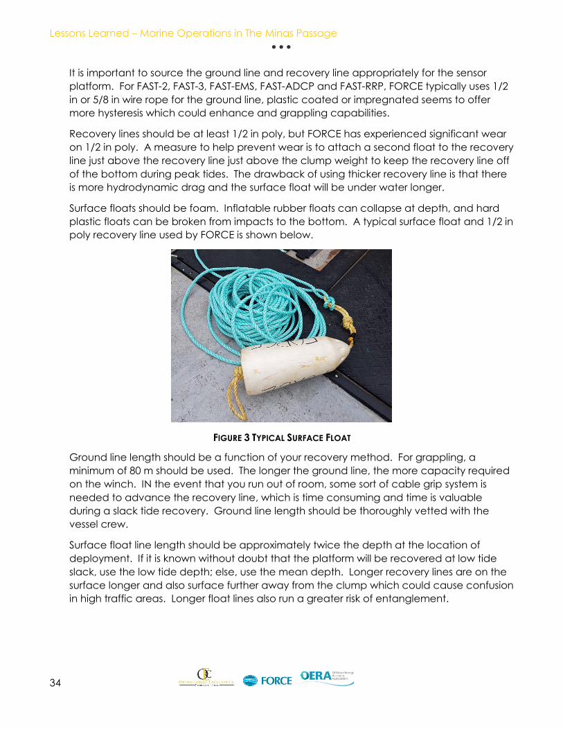
Surface floats should be foam. Inflatable rubber floats can collapse at depth, and hard
plastic floats can be broken from impacts to the bottom. A typical surface float and 1/2 in
poly recovery line used by FORCE is shown below.
FIGURE 3 TYPICAL SURFACE FLOAT
Ground line length should be a function of your recovery method. For grappling, a
minimum of 80 m should be used. The longer the ground line, the more capacity required
on the winch. IN the event that you run out of room, some sort of cable grip system is
needed to advance the recovery line, which is time consuming and time is valuable
during a slack tide recovery. Ground line length should be thoroughly vetted with the
vessel crew.
Surface float line length should be approximately twice the depth at the location of
deployment. If it is known without doubt that the platform will be recovered at low tide
slack, use the low tide depth; else, use the mean depth. Longer recovery lines are on the
surface longer and also surface further away from the clump which could cause confusion
in high traffic areas. Longer float lines also run a greater risk of entanglement.
Lessons Learned – Marine Operations in The Minas Passage
35
FORCE typically uses a ~500 lbs clump weight, though ~100 lbs clumps have been used
when necessary.
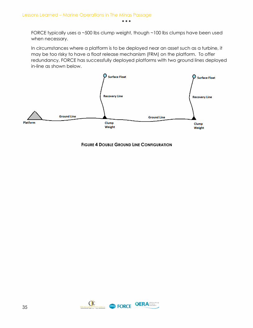
In circumstances where a platform is to be deployed near an asset such as a turbine, it
may be too risky to have a float release mechanism (FRM) on the platform. To offer
redundancy, FORCE has successfully deployed platforms with two ground lines deployed
in-line as shown below.
FIGURE 4 DOUBLE GROUND LINE CONFIGURATION

Lessons Learned – Marine Operations in The Minas Passage
36
The following is a for a recovery with the Nova Endeavor:
Recovery Procedure
Item
No.
Task
1. Approximately one hour before low water slack, the acoustic release securing
the FRM on the platform will be interrogated. Ranging on the acoustic release
will determine if the platform is still at the deployed position.
2. When the Person in Charge determines that the tide conditions are favorable
the acoustic release will be actuated and the recovery floats and rope will
surface.
3. On the Person in Charge’s command, the vessel will maneuver to recover the
floats to the deck. Enough slack will be gathered on deck to take a few wraps
around the cleat. The deckhand (under supervision of Deck Supervisor) will
remove the floats from the recovery rope and attach it to the line from the
capstan that is fed through the block on the A-frame.
4. Slack rope will be pulled in by hand by the deckhand and coiled near the
capstan. Once the recovery rope becomes tight, several turns will be wound
on the capstan and pulled in to maintain tension on the rope.
5. As the capstan recovers the rope, the Nova Endeavor E maneuvers over the
platform to keep the recovery rope as vertical as possible.
6. Once on the surface the winch wire will be attached to the lifting point by the
deckhand and the sensor platform landed on deck using the winch.
7. If the ground line surface buoy is still visible, the ground line end attached to
the platform will be disconnected and tossed overboard.
Contingency step: If the ground line surface buoy is not visible, the ground line
slack will be recovered to the vessel by hand by the deckhand. Once as much
ground line slack as possible is recovered, the deckhand will use the wire
stoppers and winch will be used to recover the last of the ground line and the
anchor. The anchor will then be brought onto the deck.
8. Once the sensor platform is secured the Person in Charge will notify the
Captain to will maneuver to recover the ground line buoy and attached rope.
9. The rope will be attached to the capstan by the deckhand and the ground
line anchor weight lifted to the surface.
10. With the ground line anchor on board the ground line can be recovered by
hand or with assistance from the winch at the deckhand’s discretion.
In the event of an Float Release Mechanism (FRM) failure, the recovery starts at the
surface float. If the surface float has also been compromised, the recovery must be made
by means of grappling for the ground line.

Lessons Learned – Marine Operations in The Minas Passage
37
Grappling Recovery Procedure
Vessels should be equipped with purpose build grapnels for grappling small gauge ground
lines:
FIGURE 5 TYPICAL STYLE OF GRAPNELS
The following is a for a grappling recovery with the Nova Endeavor:
Grappling Recovery Procedure
Item
No.
Task
1. On slack tide, the vessel will approach the ground line at the middle and drag
the grapnel for recovery; attempts will be made at the Nova Endeavor’s Deck
Boss’ discretion.
2. If mid-point grappling is unsuccessful, the Nova Endeavor will take additional
runs for the ground line while incrementally proceeding toward the clump.
3. If progression toward the clump is unsuccessful, the vessel will take additional
runs for the ground line while incrementally proceeding toward the platform.
4. Once grappling is successful, the ground will be brought to the surface and at
the vessel’s Deck Boss’ discretion, progress will be made toward the clump or
the platform, depending on where and how the ground line was collected.
5. Recovery will be done using the same winch / wire stopper method described
above.
To mitigate the risk of grappling procedures, the minimum distance between parallel
ground line arrangements in any deployment area should be 50 m. Ideal distance
between ground line arrangements is 150 m or more.

Lessons Learned – Marine Operations in The Minas Passage
38
Post Deployment Condition Report for the Fundy Advanced Sensor Technology (FAST)
Platform - September 2017 Deployment -Source: POST- DEPLOYMENT CONDITION REPORT FOR THE FUNDY
ADVANCED SENSOR TECHNOLOGY (FAST 3) PLATFORM SEPTEMBER 2017 DEPLOYMENT – T. Windeyer with Tyler Boucher and
Haley Viehman. Full report in appendix 2.
The FAST 3 Small Autonomous Sensor Platform has been developed to provide
oceanographic and environmental data for design engineering purposes and
environmental monitoring. It is equipped with instrumentation to provide data on fish and
marine life as well as tidal currents and water quality in the water column near the tidal
energy site. This is the third stage of the oceanographic data acquisition program
implemented by FORCE.
Platform Description
Photo below shows the platform and instruments setup and ready in the workshop prior to
deployment. Table 1.1 lists the instrument mounted on the platform and their functions.
FIGURE 6 PHOTO HALEY VIEHMAN – FAST PLATFORM
Lessons Learned – Marine Operations in The Minas Passage
39
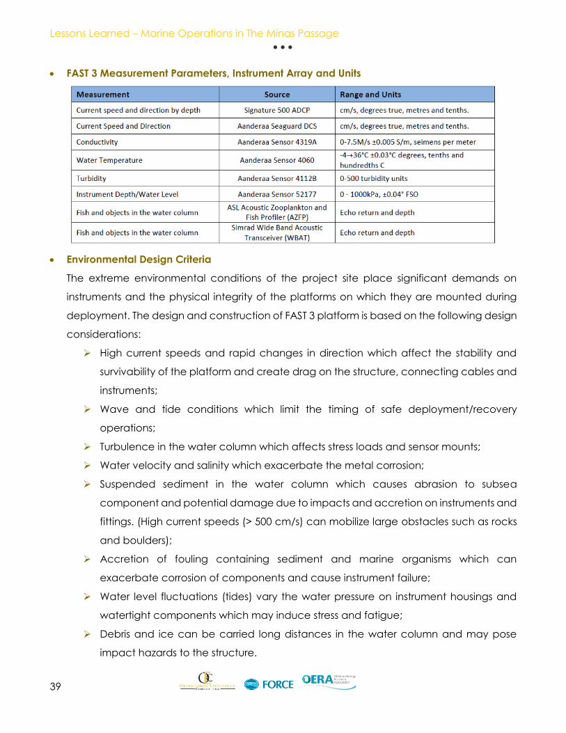
FAST 3 Measurement Parameters, Instrument Array and Units
Environmental Design Criteria
The extreme environmental conditions of the project site place significant demands on
instruments and the physical integrity of the platforms on which they are mounted during
deployment. The design and construction of FAST 3 platform is based on the following design
considerations:
High current speeds and rapid changes in direction which affect the stability and
survivability of the platform and create drag on the structure, connecting cables and
instruments;
Wave and tide conditions which limit the timing of safe deployment/recovery
operations;
Turbulence in the water column which affects stress loads and sensor mounts;
Water velocity and salinity which exacerbate the metal corrosion;
Suspended sediment in the water column which causes abrasion to subsea
component and potential damage due to impacts and accretion on instruments and
fittings. (High current speeds (> 500 cm/s) can mobilize large obstacles such as rocks
and boulders);
Accretion of fouling containing sediment and marine organisms which can
exacerbate corrosion of components and cause instrument failure;
Water level fluctuations (tides) vary the water pressure on instrument housings and
watertight components which may induce stress and fatigue;
Debris and ice can be carried long distances in the water column and may pose
impact hazards to the structure.
Lessons Learned – Marine Operations in The Minas Passage
40
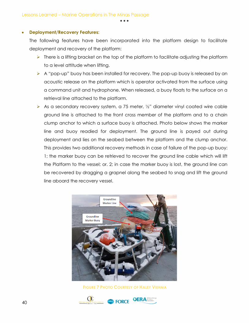
Deployment/Recovery Features:
The following features have been incorporated into the platform design to facilitate
deployment and recovery of the platform:
There is a lifting bracket on the top of the platform to facilitate adjusting the platform
to a level attitude when lifting.
A “pop-up” buoy has been installed for recovery. The pop-up buoy is released by an
acoustic release on the platform which is operator activated from the surface using
a command unit and hydrophone. When released, a buoy floats to the surface on a
retrieval line attached to the platform.
As a secondary recovery system, a 75 meter, ½” diameter vinyl coated wire cable
ground line is attached to the front cross member of the platform and to a chain
clump anchor to which a surface buoy is attached. Photo below shows the marker
line and buoy readied for deployment. The ground line is payed out during
deployment and lies on the seabed between the platform and the clump anchor.
This provides two additional recovery methods in case of failure of the pop-up buoy:
1; the marker buoy can be retrieved to recover the ground line cable which will lift
the Platform to the vessel; or. 2; in case the marker buoy is lost, the ground line can
be recovered by dragging a grapnel along the seabed to snag and lift the ground
line aboard the recovery vessel.
FIGURE 7 PHOTO COURTESY OF HALEY VIEHMA

Lessons Learned – Marine Operations in The Minas Passage
41
MOORING TRIALS AND DATA CABLE RECOVERY
Source: Prepared by - R.J. MacIsaac Construction Ltd. / Seaforth Geosurveys Inc. for FORCE.
Station-keeping and cable recovery trials were conducted using RJ MacIsaac’s TKL5
barge in the Bay of Fundy. The following document contains a detailed report of the
objectives, approach, and results of trial operations over the duration of the project, from
June 2014 to December 2015. Through strategic, detailed planning and constant risk
management, project operations were executed safely and effectively. The experience
and site knowledge gained throughout project operations provided valuable information
for future project planning.
The project objectives were two-fold:
1. To develop and demonstrate a method of maintaining a work vessel on
station, within a limited range of movement, for a defined period of time, and
2. to apply this method to recovery of the subsea data cable at FORCE.
Specific criteria for movement range and timeframe were established to
evaluate demonstrated station-keeping ability.
The suite of marine assets and equipment used in the trials included the TKL5, two tugs
(primary tug and support tug), a safety vessel, and several winches and specialized lifting
and anchor equipment. Procedures to deploy and recover the anchors were developed
and tested in both low-flow and high-flow test sites; procedures and equipment were
revised throughout the project, to improve safety, capacity and efficiency.
Trials were conducted over 4 phases, primarily in neap tide conditions with the exception
of one set of spring tide trials. Precise position-monitoring was used to track barge
movement. Three different anchor types were tested, with two deemed suitable to safely
hold the barge at anchor in various seabed types for the duration of a half tidal cycle
(flood or ebb). A final anchor assembly was designed that incorporated different anchor
holding mechanisms, adding redundancy to the mooring. A stern anchor was added in
the final demonstration, and initially resulted in reduced barge movement before losing
hold of the seabed.
A test tackle assembly was used to test the procedures developed for cable recovery.
During the final trial phase, a station-keeping and test tackle recovery demonstration was
executed; while the performance did not meet the full requirements, the results were
deemed sufficiently accurate to proceed to cable recovery. Data cable recovery was
initiated but was aborted due to failure of the cable mooring.
Safety, hazard assessment, and risk management were major considerations throughout
the project, and safety considerations were integrated into all project decisions. Detailed

Lessons Learned – Marine Operations in The Minas Passage
42
project safety plans were developed and communicated to maintain safe working
conditions.
The station-keeping and cable recovery trials successfully demonstrated a method of
establishing and maintaining station with the equipment and configuration used in these
trials. However, the trials did not meet the original criteria, indicating that there may be a
limit to the minimum movement range that can be feasibly achieved with this approach.
The following recommendations are presented based on trial outcomes:
1. A three-point anchor system, using a primary bow anchor and two positioning anchors,
is likely the most effective approach for maintaining station with minimal movement.
This approach would be recommended for cases where the primary anchor can be
deployed directly from the bow, thus reducing deployment time and eliminating the
need for a preestablished mooring.
2. A detailed analysis should be conducted to determine the minimum capacity of the
primary tug. Limitations in tug capabilities can significantly hinder project operations
and can introduce additional risks.
3. Detailed project planning, that addresses safety, risk management, weather
conditions, and coordination/communication, and strategic scheduling, that accounts
for tidal cycle, flow conditions, daylight hours, and transit times, are crucial for
successful station keeping operations. Knowledge of unique site conditions, including
variation in flow speeds, water depth range, and seabed characteristics, should be
incorporated into project plans. Full Report can be found in Appendix 4 Station
keeping and mooring trials.
FIGURE 8 TEST LOCATIONS

Lessons Learned – Marine Operations in The Minas Passage
43
This document touches a bit on the FAST program and more detailed information about FAST
can be found in Appendix 2.
Lessons Learned – Marine Operations in The Minas Passage
44
Vendors A wide variety if vendors are used and have contributed to the marine operations in support of
the tidal industry in Nova Scotia. Many of these have been compiled by Marine Renewables
Canada and are listed in their Supply Chain database.
Marine Renewables Canada developed Canada’s first database solely focused on the supplier
capabilities for marine renewable energy projects. Through a publicly accessible online
platform, the database assists in identifying, assessing, and engaging businesses and
organizations with capabilities that can aid in the advancement of the marine renewable
energy sector. It also helps to ensure that Canada’s supplier strengths are profiled amongst other
jurisdictions that are putting significant investment and resources into building their marine
renewable energy supply chain and have developed similar tools.

Appendix 1: Vessel Information
Appendix 2: FAST Reports

Appendix 3: Diving

Appendix 4: Station Keeping / Mooring
Trials

Appendix 5: Video
Oceaneering ROV Video
ROV Video 1
ROV Video 2
ROV Video 3
Dive Operations Video
FAST Platform Dive Video

Acknowledgments:
This report was made possible through the cooperation of the companies mentioned below.
Further updating of this document will be required as this is essentially a “Live” document. As
activity in the Minas Passage and the surrounding Bay of Fundy increase it is the hope that this
information will expand, and a yearly update can be released with the assistance a
cooperation of all involved in activities in the Bay of Fundy.
I thank all that have provided input to this report and look forward to working with you all in
the future.