Lesson Plan – Hall EffectLesson Plan – Capacitors and Oscillating Circuits – Patterson 3...
31
Lesson Plan – Capacitors and Oscillating Circuits – Patterson 1 Lesson Plan – Capacitors, Inductors, and Oscillating Circuits Georgia Institute of Technology STEP-UP Summer 2018 Kenneth Patterson Gwinnett School of Math Science & Technology Lawrenceville, GA Subject: Physics – Electricity & Magnetism Grade: 9-11 Suggested Time: Two 50 minute periods Topics Review of Solenoids/Inductors Introduction to Capacitors Application of both in an Oscillating Circuit (LC Circuit) Problem / Essential Questions - How does a coil of wire (an electromagnet) behave in an electric circuit? - What is a capacitor and what properties affect capacitance? - How are oscillations produced in an electric circuit? - What are some applications of inductors and capacitors? Abstract Standard honors-level physics curriculum covers electricity and circuit elements up to combination circuits using resistors only. This lesson serves as an extension to this curriculum by introducing capacitors and inductors at a non-mathematical level. The lesson involves students investigating the properties that cause capacitance by making their own capacitor out of two sheets of aluminum foil and two sheets of an insulating layer. The lesson introduces the application of inductors and capacitors by showing how both are used together to produce oscillations. Finally, the lesson concludes with a lab assessment where students use an online circuit simulator to build and analyze their own LC circuits.
Transcript of Lesson Plan – Hall EffectLesson Plan – Capacitors and Oscillating Circuits – Patterson 3...
Lesson Plan – Capacitors and Oscillating Circuits – Patterson
1
Lesson Plan – Capacitors, Inductors, and Oscillating Circuits
Georgia Institute of Technology STEP-UP Summer 2018
Kenneth Patterson
Gwinnett School of Math Science & Technology Lawrenceville, GA
Subject: Physics – Electricity & Magnetism Grade: 9-11 Suggested Time: Two 50 minute periods
Topics
Review of Solenoids/Inductors Introduction to Capacitors Application of both in an Oscillating Circuit (LC Circuit)
Problem / Essential Questions
- How does a coil of wire (an electromagnet) behave in an electric circuit? - What is a capacitor and what properties affect capacitance? - How are oscillations produced in an electric circuit? - What are some applications of inductors and capacitors?
Abstract Standard honors-level physics curriculum covers electricity and circuit elements up to combination circuits using resistors only. This lesson serves as an extension to this curriculum by introducing capacitors and inductors at a non-mathematical level. The lesson involves students investigating the properties that cause capacitance by making their own capacitor out of two sheets of aluminum foil and two sheets of an insulating layer. The lesson introduces the application of inductors and capacitors by showing how both are used together to produce oscillations. Finally, the lesson concludes with a lab assessment where students use an online circuit simulator to build and analyze their own LC circuits.
Lesson Plan – Capacitors and Oscillating Circuits – Patterson
2
Alignment with State and Local Standards Georgia Standards of Excellence
SP5. Obtain, evaluate, and communicate information about electrical and magnetic force interactions
d. Plan and carry out an investigation of the relationship between voltage, current, and power for direct current circuits e. Plan and carry out investigations to clarify the relationship between electric currents and magnetic fields.
Gwinnett County Schools Physics AKS D – Electricity and Magnetism
Analyze (via laboratory analysis) the properties of magnetic fields and their relationship to electric fields.
Objectives
- To introduce parallel-plate capacitors to students for the first time. Students need not analyze the mathematical behavior of capacitors in series and parallel.
- To expose students to Capacitors and Inductors before they see these devices in AP Physics
- To have students build their own capacitor and investigate properties - To show how an LC circuit creates oscillations and is used in modern electronics
Anticipated Learner Outcomes Students will be able to
1. Describe that a capacitor is made of two conducting parallel plates separated by an insulating layer 2. Investigate how surface area of the plates and distance of separation affects the total capacitance of a device 3. Draw electrical schematics using capacitors and inductors 4. Calculate the frequency of oscillation of an LC circuit
Background
Prior Knowledge – before beginning the lesson, students should already be familiar with
- Series and Parallel electric circuits - Electromagnetic induction - Solenoids and electromagnet coils - The definition of frequency and measurement of frequency in Hertz (Hz)

Lesson Plan – Capacitors and Oscillating Circuits – Patterson
3
Lesson Info This lesson begins with a review of solenoids and the creation of a magnetic field around a coil of current-carrying wire.
As seen above, a coil of wire carrying current I will create a magnetic field inside of and around the coil. Students learn this as an electromagnet in their earlier science education. For this lesson, introduce to students that this device is also called an inductor in electric circuit diagrams. While both words refer to essentially the same basic device in physics, there are key differences between the two in the field of engineering. The main difference between the two words is that an electromagnet is specifically used to create a strong magnet or magnetic field whereas an inductor is used to control the rate of change of current in an electric circuit. Inductance is represented by the symbol L and is measured in the unit of Henries. The voltage across an inductor is given by:
𝑉𝑉 = −𝐿𝐿𝑑𝑑𝑑𝑑𝑑𝑑𝑑𝑑
meaning that a potential difference only exists when the current in the coil is changing. When powered on in a DC circuit, the inductor will store increasing energy in its magnetic field until reaching maximum current. Once the current is steady and unchanging, the inductor’s magnetic field will be constant. If the DC power is switched off, then the current begins decreasing negatively. This means that the inductor will continue to supply positive voltage to the circuit, even after the power is turned off! The energy is stored in the magnetic field, and the current will slowly decrease as this energy is released. In the Georgia Standards of Excellence for high school Physics, studying circuit elements such as inductors and capacitors is not required. However, in AP Physics students will need to do analysis and calculation of circuits with L and C. Therefore, the function of this lesson’s content is a “first look” into what an inductor or capacitor is for an on-level Physics student, so that they will have seen these devices at least once before taking an advanced Physics course. A capacitor is a pair of conducting plates or sheets of area A offset by some gap of distance d. Between the two conductors is an insulator. In most simple diagrams this insulator is drawn as air, but in actual devices the insulator is any solid insulating material and is called the dielectric. A diagram of a capacitor is shown on the next page

Lesson Plan – Capacitors and Oscillating Circuits – Patterson
4
Because the two conducting plates do not make contact, a capacitor will block sustained current flow in a DC circuit. The function of a capacitor is to store a large quantity of electric charges. A capacitor can do this because of the large surface area of the two plates. The amount of charge that a capacitor can hold is related to its capacitance, C, measured in Farads, which is determined by its geometry and the properties of the dielectric:
𝐶𝐶 = 𝜀𝜀𝑟𝑟𝜀𝜀0𝐴𝐴𝑑𝑑
Where 𝜀𝜀𝑟𝑟 is the dielectric constant of the material, and 𝜀𝜀0 is the electric permittivity of free space 8.854 x 10⁻¹² F/m. In this lesson students will NOT be using the electric constants to calculate capacitance, but will rather be building a capacitor out of aluminum foil and an insulating layer of their choice to investigate how to make a more effective capacitor with a larger value of C. Students should attempt to maximize two-dimensional Area of the conductive sheets while minimizing the distance between them. It is critical that students understand that even though a capacitor seems like an open circuit, in DC a current will flow briefly while the capacitor is charging or discharging. Positive “charges” (in actuality: a lack of negative electrons) flow onto the positive terminal, while negative charges flow onto the negative terminal, until the potential difference across the two plates is equal to the voltage of the battery:

Lesson Plan – Capacitors and Oscillating Circuits – Patterson
5
The first part of the lesson introduces the concept of capacitance and how capacitors can store electric charge. The second part of the lesson shows how combining a capacitor and an inductor in a circuit (an LC Circuit) produces sinusoidal oscillations.
Pictured is the simplest possible LC circuit. Note, it is important that the capacitor begins in a fully-charged state. The capacitor will discharge through the inductor, which will allow the current to slowly rise. Once the current is maximum, the capacitor is discharged and the inductor’s magnetic field is at maximum. The inductor will now keep the current flowing which will re-charge the capacitor in the opposite direction. Once the current reaches zero, the capacitor will now discharge in the opposite direction which repeats the cycle all over again. The result is an I vs t chart which looks like:
The charging-discharging-recharging oscillating nature of the LC circuit is best seen in an animation, which can be seen here: https://i.imgur.com/xFNC2k7.gifv The oscillation frequency is given by
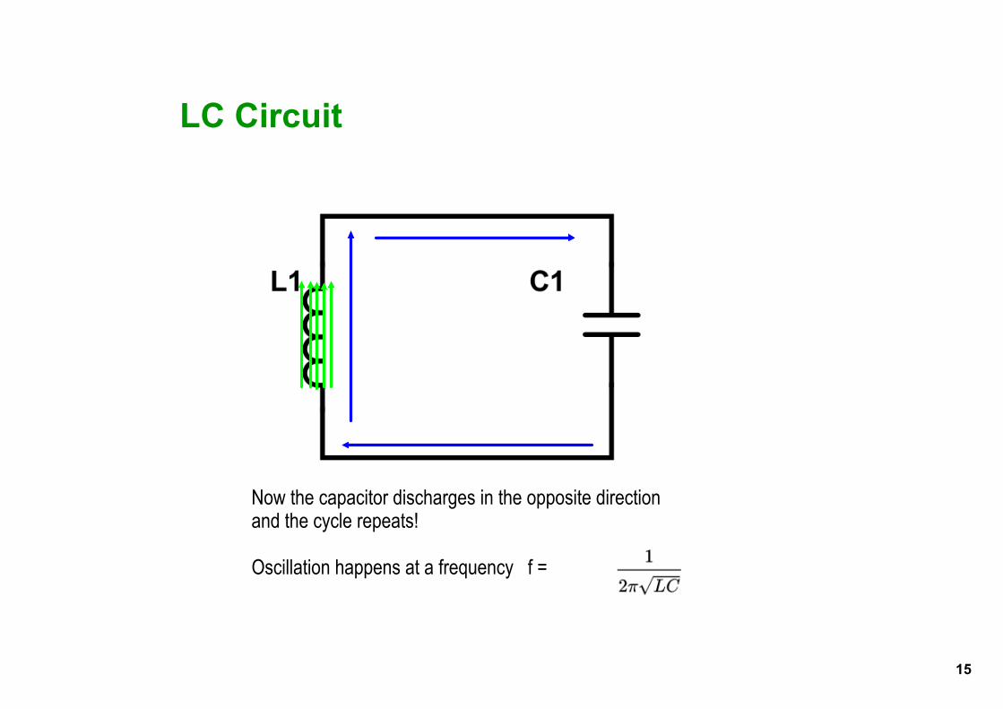
𝑓𝑓 = 1
2𝜋𝜋√𝐿𝐿𝐶𝐶
The above chart is only possible if the capacitor, inductor, and wires have a perfectly zero resistance. Of course, for real objects the electrical resistance will be non-zero, meaning the oscillations will decrease in amplitude over time due to loss of energy. In engineering practice, an oscillating circuit will have an input source of energy, the LC circuit will be used to produce oscillations, and this frequency will be fed to a resistive load like an antenna.

Lesson Plan – Capacitors and Oscillating Circuits – Patterson
6
Building a homemade capacitor A capacitor can be made of simple household materials, for students to investigate what capacitance is and how it works. Check the Materials section below for a list of needed materials, seen here:
Step 1 – Lay out a few feet of insulator (in these pictures, wax paper is used, though plastic wrap or regular paper will also work as an insulating layer. Lay out the same length of aluminum foil, and place the foil on top of the insulator.
Step 2 – Make sure that the aluminum sheet is about 1 inch smaller in all dimensions than the wax paper sheet. The conducting layers of a capacitor must NOT TOUCH and it is critical that the aluminum does not overhang the paper.

Lesson Plan – Capacitors and Oscillating Circuits – Patterson
7
Step 3 – Lay out a second sheet of wax paper on top of the first sheet of aluminum, then lay a second sheet of aluminum atop of the stack. You should have a stack alternating between insulating and conducting layers, making sure that the CONDUCTING LAYERS DO NOT TOUCH. Step 4 – Lift up the layers a bit and tape a paperclip to the bottom conductor so that it overhangs the edges. Tape a second paperclip to the top conductor. These will be the terminals of the capacitor.
Step 5 – Use a paper towel tube or other circular tube to roll the 4 layers into a cylinder. As always, while rolling, take care that the conducting layers do not slip and touch.

Lesson Plan – Capacitors and Oscillating Circuits – Patterson
8
Step 6 – Use a multimeter to measure the capacitance of your capacitor. You will need to use a high-quality multimeter that has the capacitance ( ) feature. This particular capacitor is about 150nF.
Sadly, the homemade capacitor will most likely be on the order of a few hundred nF, which means it won’t hold enough energy to produce any easily observable effects in a classroom setting. If you want to build an LC circuit that can demonstrate some visible oscillation you can use or order some commercial circuit elements (for example from www.sparkfun.com). The spiral roll is how most large capacitors are made, because it maximizes surface area while minimizing total volume.

Lesson Plan – Capacitors and Oscillating Circuits – Patterson
9
Materials – At least one per group of
• Aluminum Foil • Wax Paper • Plastic wrap • Paper clips • Paper towel tube
• Paper • Alligator clips • Tape (any kind) • Multimeter WITH capacitance meter
Plan
This lesson is split into two parts. It can be taught as
one 90 minute lesson or two shorter lessons.
The table below lays out a “schedule” for the two-lesson sequence: Part 1:
Teacher is doing: Time Students are doing: Begin lesson with a review of electromagnets. A current-carrying coil creates a magnetic field. Ask student questions to activate background knowledge
5 min Reviewing with their notes and with a discussion with the class and teacher Answering review questions posed by teacher
Go through lecture on attached slides on Capacitors (see appendix)
20 mins Listening and making notes
Introduce “Make your own capacitor” materials and instructions. Hand out necessary tools and materials
5 min Listening to instructions Preparing materials
Circulate and assist students building their capacitor
15 min Building a capacitor using the required materials, either alone or in a small group Discussing and observing with each other
Test! Go to each student (or student group’s) capacitor, and use a multimeter to measure their capacitance
5 min Observing and recording the effectiveness of their capacitor

Lesson Plan – Capacitors and Oscillating Circuits – Patterson
10
Part 2:
Teacher is doing: Time Students are doing: Begin Lesson 2 by reviewing Lesson 1 5 mins Listening and answering teacher questions
Lecture and show the operation of an oscillating LC circuit (see appendix)
15 mins Listening and making notes
Assisting students with online lab activity
25 min Going through the “LC Circuit Simulator Lab and Activity” Students are online at phet.colorado.edu, interacting with the online AC/DC circuit builder Students are writing answers to question prompts on the attached activity sheet
End the two day lesson with a discussion on what properties affected their capacitors, and what kinds of uses an LC circuit might have
5 mins Discussing their observations and conclusions
Assessment Assessment The assessment is an online lab with a student-guided worksheet (see appendix). This assessment involves students constructing a circuit in an online circuit-builder environment, and then adjusting and measuring parameters and properties, recording calculations and observations. Instructions and files are attached below.
Summary This lesson is designed to be a “first look” at two electronic devices that are normally not covered in intro-level high school Physics courses. Inductors and Capacitors are both covered in an AP Physics course, but students are often seeing those devices for the first time in that course. This lesson gives a purely conceptual look at what inductors and capacitors are and the basics of how they work. The lesson does not cover how L and C are used in most electrical engineering designs because that would require a knowledge of AC circuits. The lesson is roughly 100 minutes of classroom content which can be split into multiple days if needed. The lesson begins with the attached slides and content for lecture. Next, students will use aluminum sheets and insulating sheets to build and investigate their own capacitors. The lesson includes a second set of slides on how L and C are used together to produce oscillations. Finally, the lesson concludes with a lab assessment where students use an online circuit simulator to build and analyze their own circuits with L and C.

Lesson Plan – Capacitors and Oscillating Circuits – Patterson
11
Bibliography
“Circuit Construction Kit (AC+DC),” PhET. [Online]. Available: https://phet.colorado.edu/en/simulation/circuit-construction-kit-ac [Accessed: 01-Jul-2018].
D. Swinscoe, “Roll your own capacitors,” Phys. Educ., vol. 35, no. 1, p. 29, 2000.
E. E. World, “Electrical Engineering World: What is inside a Capacitor ? How it is
constructed?,” Electrical Engineering World, 21-Sep-2015. http://roleofelectricalengineering.blogspot.com/2015/09/what-is-inside-capacitor-how-it-is.html
“LC oscillator tutorial and tuned LC oscillator basics,” Basic Electronics Tutorials, 24-Aug-
2013. https://www.electronics-tutorials.ws/oscillator/oscillators.html
“LC Circuits,” teachTogether. [Online]. Available: http://teachtogether.chedk12.com/ [Accessed: 21-Jun-2018].

Lesson Plan – Capacitors and Oscillating Circuits – Patterson
12
APPENDIX
I. LC Circuits Lab Simulator and Activity (Handout for students)
II. Selected Presentation Slides

Lesson Plan – Capacitors and Oscillating Circuits – Patterson
13
LC Circuit – Lesson Lab and Circuit Simulator Activity
Purpose- In this lab/activity, we will model a circuit with 1 Inductor (L) and one Capacitor (C) and observe its behavior.
Setup- Go to http://phet.colorado.edu/new/simulations/sims.php?sim=Circuit_Construction_Kit_ACDC. Test the simulator’s functions, such as adding components and connecting wires.
Instructions-
Step 1 – Construct the circuit as shown:
V = 10 volts R = 5 ohms C = 0.05 Farads L = 10 Henries
Step 2 – Close Switch 1. What happens to the current after a few seconds pass?
Answer:_______________________________
______________________________________
Step 3 – The capacitor is now fully charged. Open Switch 1 and close Switch 2.
Describe the motion of the current:
_____________________________________________________________________________________
_____________________________________________________________________________________
Step 4 – Use 𝑓𝑓 = 12𝑝𝑝𝑝𝑝√𝐿𝐿𝐿𝐿
and the values of L and C above, to find the frequency of the circuit
f = ____________________
Does this match the frequency you observe? Why or why not?
__________________________________________________________________________________

Lesson Plan – Capacitors and Oscillating Circuits – Patterson
14
__________________________________________________________________________________
Step 5 – Suppose you are a circuit designer and you want to design an oscillating circuit operating at a frequency of 20,000 Hz. Select values of L and C that will produce this frequency. Design and build your circuit in the AC/DC simulator. Test your circuit, and refine it until you get the result you want!
Sketch your 20 kHz circuit below:
Step 6 – One of the major problems that Electrical Engineers are trying to solve today is called the “Terahertz Gap.” There are no electronic devices that reliably produce frequencies above 1.0 Terahertz (THz). That’s 1,000,000,000,000 Hz!
Using the formula above, select two values of L and C that would produce 1.0 THz:
L =
C =
Why do you think it is so hard to make an oscillating circuit above 1.0 THz?

1
Review! A Solenoid
• We've already learned that a coil of wire with current running through it will create a magnetic field!
• We've called this a coil, or a solenoid• In an electrical circuit diagram this is called an Inductor
• An Inductor has the letter L and the symbol or

2
Now let's introduce a new circuit element: the Capacitor
• Two metal plates separated by a gap or insulator called the "dielectric"
• The middle part of a capacitor DOES NOT CONDUCT electricity!
• Symbol for a Capacitor:

3
Capacitor in a Circuit• Suppose I make this circuit:
• At first, a capacitor seems like an open circuit, it is a GAP between two conductors that don't touch!
• But remember, unlike a wire, a capacitor can HOLD charge because it has a large surface area!
• The voltage pushes positive charges on one plate, and negative charges onto the other plate

4
A capacitor creates an electric field
• Remember: E-field lines point away from positive charges and towards negative charges
• Meaning: this circuit creates an Electric field!(In the capacitor)
Current Flow
Positive"charges"flow
Negativechargesflow
5
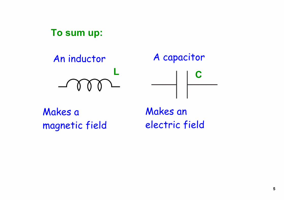
To sum up:
An inductor A capacitorL C
Makes amagnetic field
Makes anelectric field

6
Let's make our owncapacitor!
Materials:• Aluminum Foil• Wax Paper• Plastic wrap• Paper clips• Paper towel tube• Paper• Alligator clips• Tape (any kind)• Multimeter

7
Ideas!
Keep your sheetsof aluminum smallerthan sheets of yourinsulator
Your two conductingsheets can't touch!
Use 4 layers, alternate between conductor and insulator
Tape a paperclipto each conductingsheet to connectto
Roll the layersup into atube!

8
Test!We will hook amultimeter up toyour capacitor, andmeasure the"capacitance"in Farads, (F).
Who can build the capacitor with the highest capacitance?
Formula for capacitance:
A is the area of your conductive sheetd is the distance between the sheetsε is a constant (called the dielectric constant)
(Don't worry about this right now)
9
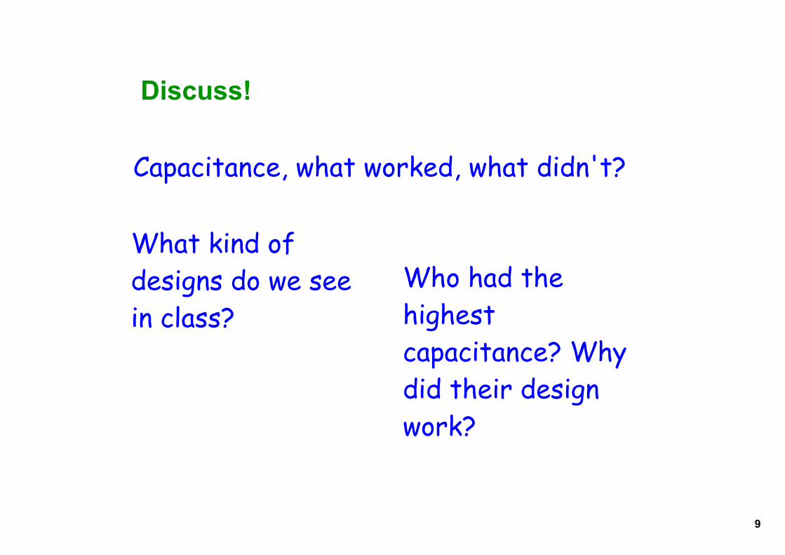
Discuss!
Capacitance, what worked, what didn't?
What kind of designs do we seein class?
Who had the highest capacitance? Why did their design work?
10
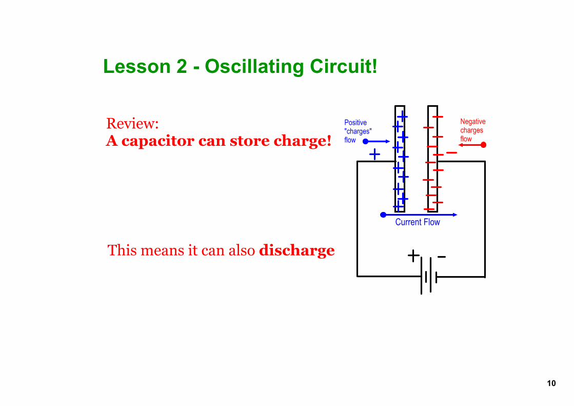
Lesson 2 Oscillating Circuit!
Review:A capacitor can store charge!
This means it can also discharge
Current Flow
Positive"charges"flow
Negativechargesflow
11
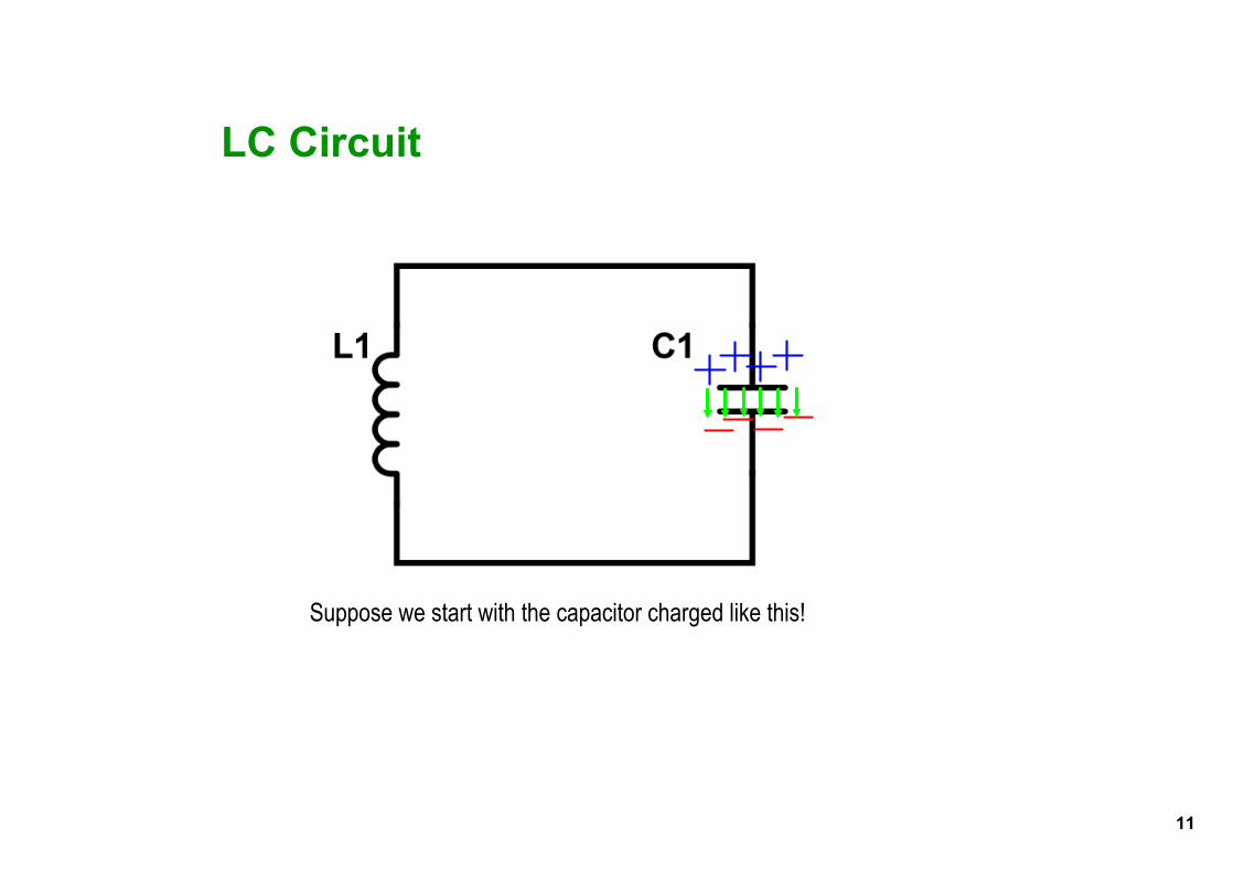
LC Circuit
Suppose we start with the capacitor charged like this!

12
LC Circuit
The capacitor will discharge, current will flowthrough the inductor, creating a magnetic field
I

13
LC Circuit
The inductor keeps the current going, slowly rechargingthe capacitor in the opposite direction
I

14
LC Circuit
Until the current goes to zero, now the Efield is atmaximum again!
15
LC Circuit
Now the capacitor discharges in the opposite directionand the cycle repeats!
Oscillation happens at a frequency f =

16
LC Circuit simulator lab and activity
Go to http://phet.colorado.edu/new/simulations/sims.php?sim=Circuit_Construction_Kit_ACDC

17