Switches Displays Solenoids Motors - h Ac
50
1 Dr. Martin Land Peripheral Interfacing Embedded Systems — Hadassah College — Spring 2011 Hello Physical World Switches Displays Solenoids Motors
Transcript of Switches Displays Solenoids Motors - h Ac

1Dr. Martin LandPeripheral InterfacingEmbedded Systems — Hadassah College — Spring 2011
Hello PhysicalWorldSwitches
Displays
Solenoids
Motors

2Dr. Martin LandPeripheral InterfacingEmbedded Systems — Hadassah College — Spring 2011
Inputs + Switches
Power supplySupply voltage (VDD) = logic 1Ground = logic 0
Switch Open — disconnectClosed — connect
Switch with pull-up resistorOpen switch
Input pin = +voltage = logic 1Resistor does nothing
Closed switchInput pin = ground = logic 0Resistor prevents short circuit of VDD to ground
PIC configurable with internal pull-up resistors
InputPin
VDD
0 RSwitch
1
Physical abstraction model
InputPin
0
InputPin
VDD
1

3Dr. Martin LandPeripheral InterfacingEmbedded Systems — Hadassah College — Spring 2011
Light Emitting Diode (LED)
Output pin → resistor → LED → groundOutput pin = logic 1
Current through LED LED emits light
Output pin = logic 0 No current through LEDLED off
VDD → resistor → LED → output pinOutput pin = logic 0
Current through LED to output pinLED emits light
Output pin = logic 1 No current through LEDLED off
OutputPin
VDD
Physical abstraction model
OutputPin
4Dr. Martin LandPeripheral InterfacingEmbedded Systems — Hadassah College — Spring 2011
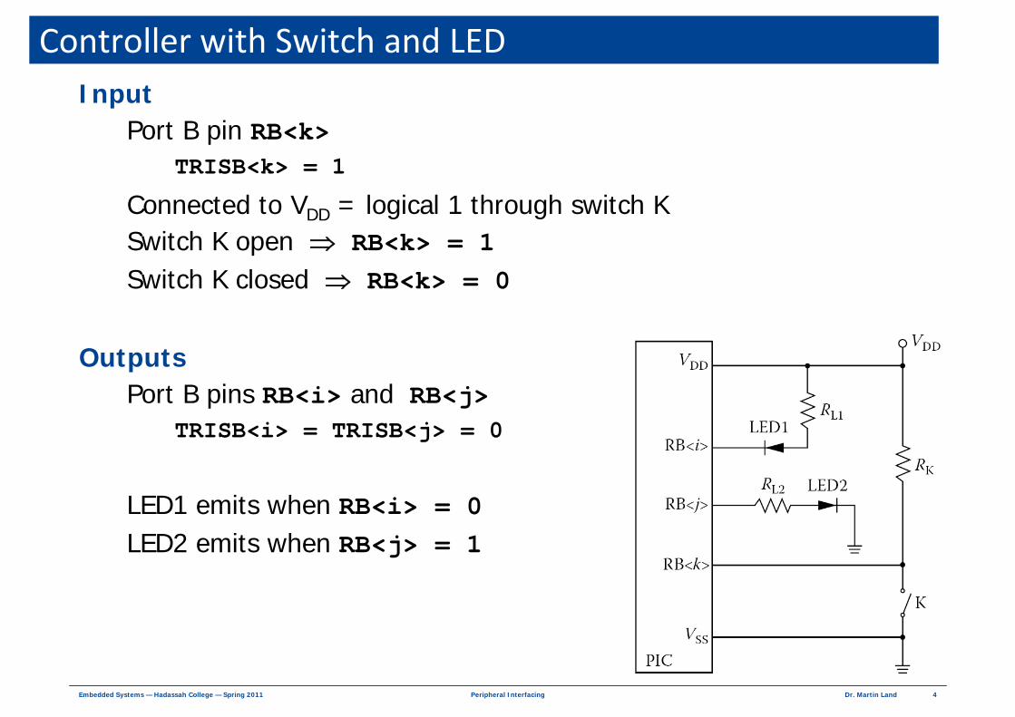
Controller with Switch and LEDInput
Port B pin RB<k>TRISB<k> = 1
Connected to VDD = logical 1 through switch KSwitch K open ⇒ RB<k> = 1 Switch K closed ⇒ RB<k> = 0
OutputsPort B pins RB<i> and RB<j>
TRISB<i> = TRISB<j> = 0
LED1 emits when RB<i> = 0LED2 emits when RB<j> = 1
5Dr. Martin LandPeripheral InterfacingEmbedded Systems — Hadassah College — Spring 2011
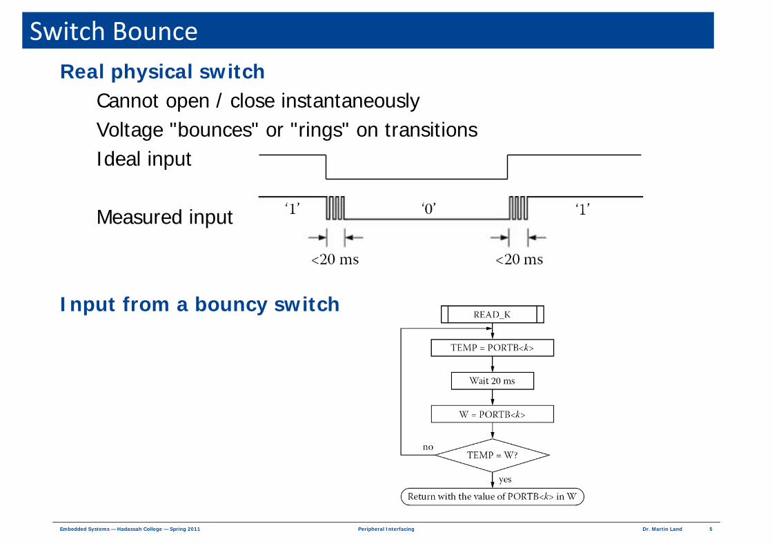
Switch BounceReal physical switch
Cannot open / close instantaneouslyVoltage "bounces" or "rings" on transitionsIdeal input
Measured input
Input from a bouncy switch

6Dr. Martin LandPeripheral InterfacingEmbedded Systems — Hadassah College — Spring 2011
Switch Input CodeTEMP equ 0x20 ; Temp data storagek equ 3 ; switch connected to RB<3> READ_K:
btfss PORTB, k ; Skip next if (RB<k> == 1)goto K0movlw 1 ; W ← 1movwf TEMP ; TEMP ← 1goto K1
K0: clrf TEMP ; TEMP ← 0K1: call wait20 ; RB<k> measured → wait 20 ms
btfss PORTB, k ; Skip next if (RB<k> == 1)goto K2movlw 1 ; W ← 1goto K3
K2: clrw ; W ← 0K3: xorwf TEMP, W ; W ← !(TEMP == W) with Z set
btfss STATUS,Z ; Skip next if (TEMP == W)goto READ_K ; Start over
K4: movf TEMP, W ; W ← TEMP
7Dr. Martin LandPeripheral InterfacingEmbedded Systems — Hadassah College — Spring 2011
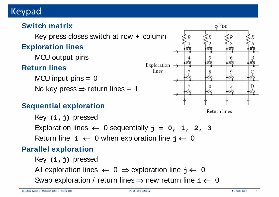
KeypadSwitch matrix
Key press closes switch at row + columnExploration lines
MCU output pins Return lines
MCU input pins = 0 No key press ⇒ return lines = 1
Sequential explorationKey (i,j) pressedExploration lines ← 0 sequentially j = 0, 1, 2, 3Return line i ← 0 when exploration line j ← 0
Parallel explorationKey (i,j) pressedAll exploration lines ← 0 ⇒ exploration line j ← 0 Swap exploration / return lines ⇒ new return line i ← 0
8Dr. Martin LandPeripheral InterfacingEmbedded Systems — Hadassah College — Spring 2011
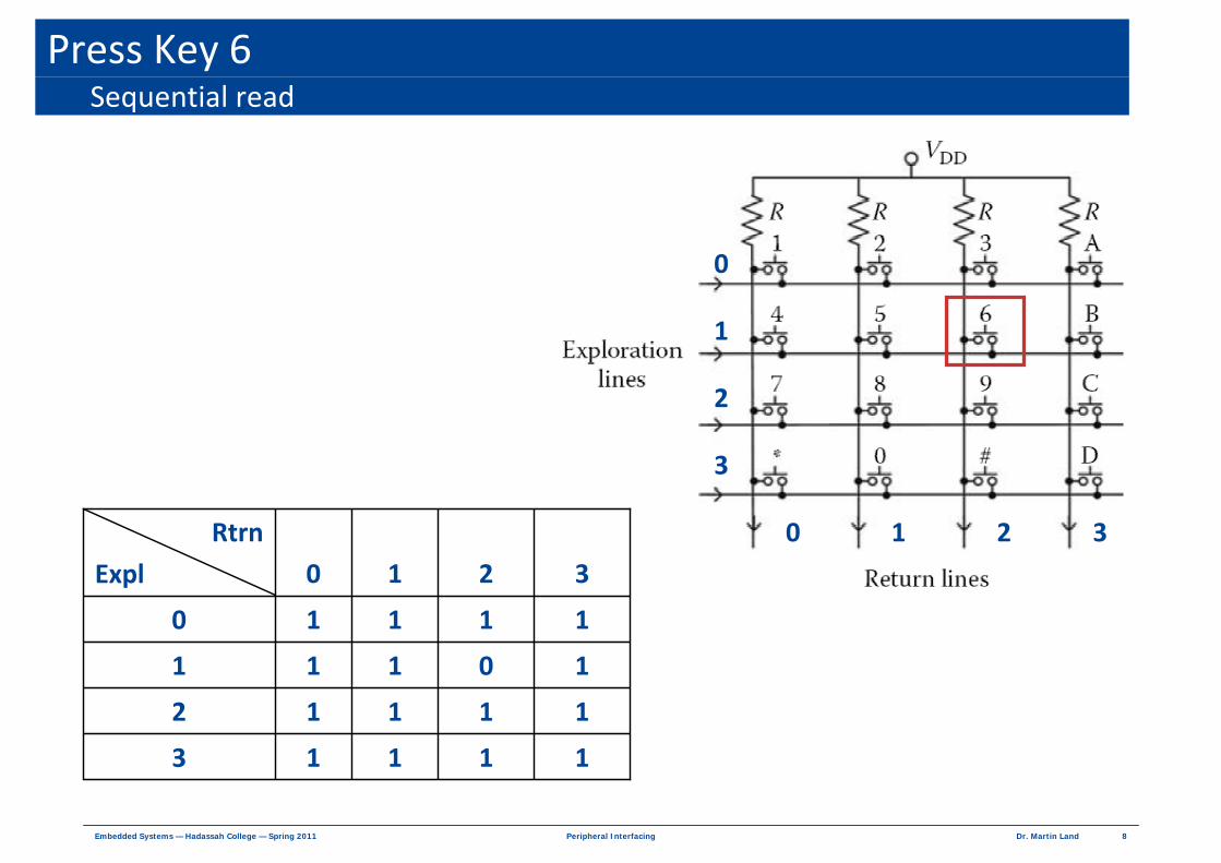
Press Key 6Sequential read
11113
11112
10 111
11110
3210
Rtrn
Expl
3
2
1
0
3210

9Dr. Martin LandPeripheral InterfacingEmbedded Systems — Hadassah College — Spring 2011
Read 1Exploration lines on rows
All rows ← 0
Return lines on columnsColumn 2 ← 0
Read 2Exploration lines on columns
All columns ← 0
Return lines on rowsRow 1 ← 0
Press Key 6Parallel read
3
2
1
0
3210

10Dr. Martin LandPeripheral InterfacingEmbedded Systems — Hadassah College — Spring 2011
Switch Matrix on PIC Port BExploration lines
RB<3:0>
Return linesRB<7:4>
Internal pull-up resistorsConfigurable on Port BRB<7:4>
Default to 1External switch can
pull down to 0
VDD
0 RSwitch
1
InputPin
PICMCU

11Dr. Martin LandPeripheral InterfacingEmbedded Systems — Hadassah College — Spring 2011
Subroutine for Keyboard Read — 1
list p = 16f873
#include <p16f873.inc>
; Declaration temporary register names
TEMP equ 0x20
ROW equ 0x21
COLUMN equ 0x22
INITKEY: ; Configure port B
clrf STATUS ; Bank 0
bcf INTCON,INTE ; Disable external interrupt by RB0
bcf INTCON, RBIE ; Disable interrupt by changes in RB<7:4>
movlw 0FFh ; Store value in PORTB
movwf PORTB ; Set all outputs in port B to 1
bsf STATUS, RP0 ; Bank 1
movlw F0h ; TRISB W ← 1111 0000 movwf TRISB ; RB<3:0> — outputs and RB<7:4> — inputs
bcf OPTION_REG, 7 ; Enable internal pull-ups in port B
bcf STATUS, RP0 ; Bank 0
return
; Configure port B
12Dr. Martin LandPeripheral InterfacingEmbedded Systems — Hadassah College — Spring 2011
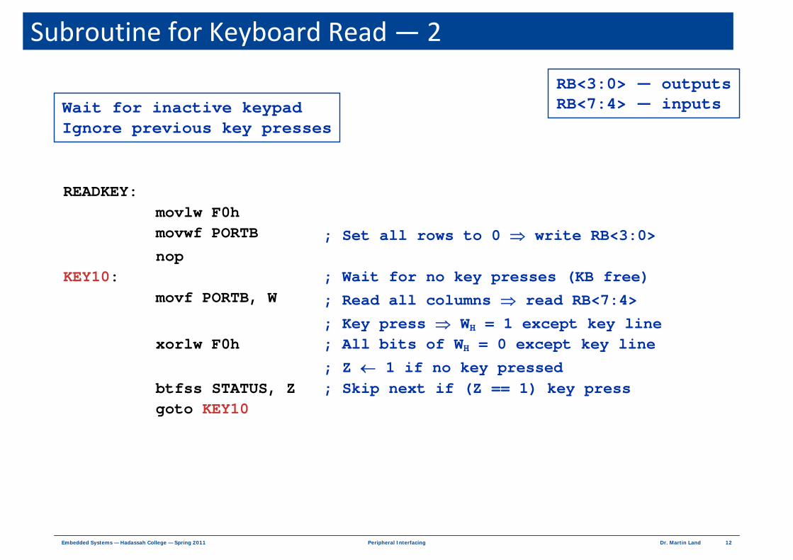
Subroutine for Keyboard Read — 2
READKEY: movlw F0h movwf PORTB ; Set all rows to 0 ⇒ write RB<3:0> nop KEY10: ; Wait for no key presses (KB free) movf PORTB, W ; Read all columns ⇒ read RB<7:4> ; Key press ⇒ WH = 1 except key line xorlw F0h ; All bits of WH = 0 except key line ; Z ← 1 if no key pressed btfss STATUS, Z ; Skip next if (Z == 1) key press goto KEY10
Wait for inactive keypadIgnore previous key presses
RB<3:0> — outputsRB<7:4> — inputs

13Dr. Martin LandPeripheral InterfacingEmbedded Systems — Hadassah College — Spring 2011
Subroutine for Keyboard Read — 3
KEY20: movlw F0h ; Repeat reading of input lines movwf PORTB ; testing of lines nop ; waiting for key press movf PORTB, W xorlw F0h btfsc STATUS, Z ; Skip next if !(Z == 1) ⇒ key press goto KEY20 KEY30: ; Continue on key press call DELAY20 ; 20 ms delay for debouncing KEY40: ; Explore keypad row by row movlw FFh ; All rows to 1 movwf PORTB nop ROW0: ; Explore row 0 movlw 0 ; W ← 0 movwf ROW ; ROW ← W bcf PORTB, 0 ; Row 0 ← 0 (RB0) nop movf PORTB, W ; Read all columns simultaneously call IDENTIFY ; Subroutine to identify column btfsc STATUS, C ; Skip next if (C == 1) goto KEY50 ; Finish exploration bsf PORTB, 0 ; Row 0 ← 1 (RB0) nop
Explore Row 0
Wait for key press
14Dr. Martin LandPeripheral InterfacingEmbedded Systems — Hadassah College — Spring 2011
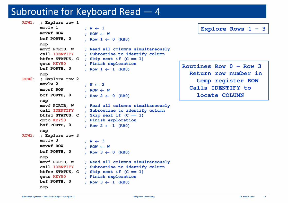
Subroutine for Keyboard Read — 4
Explore Rows 1 – 3ROW1: ; Explore row 1 movlw 1 ; W ← 1 movwf ROW ; ROW ← W bcf PORTB, 0 ; Row 1 ← 0 (RB0) nop movf PORTB, W ; Read all columns simultaneously call IDENTIFY ; Subroutine to identify column btfsc STATUS, C ; Skip next if (C == 1) goto KEY50 ; Finish exploration bsf PORTB, 0 ; Row 1 ← 1 (RB0) nop ROW2: ; Explore row 2 movlw 2 ; W ← 2 movwf ROW ; ROW ← W bcf PORTB, 0 ; Row 2 ← 0 (RB0) nop movf PORTB, W ; Read all columns simultaneously call IDENTIFY ; Subroutine to identify column btfsc STATUS, C ; Skip next if (C == 1) goto KEY50 ; Finish exploration bsf PORTB, 0 ; Row 2 ← 1 (RB0) nop ROW3: ; Explore row 3 movlw 3 ; W ← 3 movwf ROW ; ROW ← W bcf PORTB, 0 ; Row 3 ← 0 (RB0) nop movf PORTB, W ; Read all columns simultaneously call IDENTIFY ; Subroutine to identify column btfsc STATUS, C ; Skip next if (C == 1) goto KEY50 ; Finish exploration bsf PORTB, 0 ; Row 3 ← 1 (RB0) nop
Routines Row 0 – Row 3Return row number in
temp register ROWCalls IDENTIFY to
locate COLUMN

15Dr. Martin LandPeripheral InterfacingEmbedded Systems — Hadassah College — Spring 2011
Subroutine for Keyboard Read — 5
Temp registers (ROW, COLUMN) ← row, column
00000000 ≤ ROW ≤ 00000011
00000000 ≤ COLUMN ≤ 00000011
goto KEY20 ; False key pressed — start over
KEY50: ; Build 4-bit exploration code from ROW: COLUMN
rlf ROW, f ; ROW<2:1> ← row number rlf ROW, W ; W<3:2> ← row number andlw FCh ; W<1:0> ← 0 iorwf COLUMN, W ; W<1:0> ← COLUMN andlw 0Fh ; W<7:4> ← 0 return ; Return exploration code in W<3:0>
; End of main program

16Dr. Martin LandPeripheral InterfacingEmbedded Systems — Hadassah College — Spring 2011
Subroutine for Keyboard Read — 6
Subroutine IDENTIFYReturns COLUMN
IDENTIFY: movwf TEMP ; TEMP ← W btfsc TEMP, 4 ; Skip next if (column0 == 0) goto COL1 ; Next column movlw 0 ; W ← 0 movwf COLUMN ; COLUMN ← W goto IDENT_FIN ; Finish subroutine COL1: btfsc TEMP, 5 ; Skip next if (column1 == 0) goto COL2 ; Next column movlw 1 ; W ← 1 movwf COLUMN ; COLUMN ← W goto IDENT_FIN ; Finish subroutine COL2: btfsc TEMP, 6 ; Skip next if (column2 == 0) goto COL3 ; Next column movlw 2 ; W ← 2 movwf COLUMN ; COLUMN ← W goto IDENT_FIN ; Finish subroutine COL3: btfsc TEMP, 7 ; Skip next if (column3 == 0) goto COL4 ; Next column movlw 3 ; W ← 3 movwf COLUMN ; COLUMN ← W goto IDENT_FIN ; Finish subroutine COL4: bcf STATUS, C ; Return "key not pressed" as C = 0 return ; Return IDENT_FIN: bsf STATUS, C ; Return "key pressed" as C = 1 return ; Return DELAY20 ; 20 ms delay subroutine return end
17Dr. Martin LandPeripheral InterfacingEmbedded Systems — Hadassah College — Spring 2011
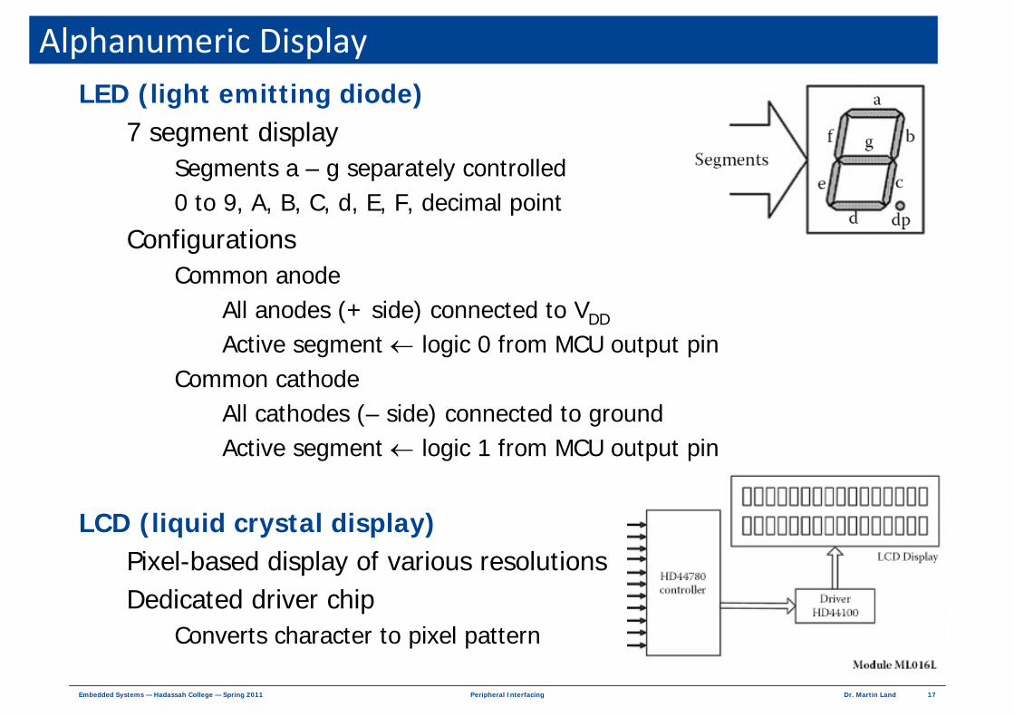
Alphanumeric DisplayLED (light emitting diode)
7 segment display Segments a – g separately controlled0 to 9, A, B, C, d, E, F, decimal point
Configurations Common anode
All anodes (+ side) connected to VDD
Active segment ← logic 0 from MCU output pinCommon cathode
All cathodes (– side) connected to ground Active segment ← logic 1 from MCU output pin
LCD (liquid crystal display)Pixel-based display of various resolutionsDedicated driver chip
Converts character to pixel pattern

18Dr. Martin LandPeripheral InterfacingEmbedded Systems — Hadassah College — Spring 2011
Seven‐Segment LED4 digit display
Port B RB<7:0> controls 7 segments + decimal RB<i> = 0 activates segmentRB<0> → a , ... , RB<6> → g , RB<7> → dp
Port A RA<3:0> selects digit to activateTransistor arrangement → RA<i> = 0 selects common anode iEach digit activated at f > 40 Hz (faster than human eye)
RA3
RA2
RA1
RA0
< 25 ms
RB7
RB6
RB5
RB4
RB3
RB2
RB1
RB0
RA3
RA2
RA1
RA0

19Dr. Martin LandPeripheral InterfacingEmbedded Systems — Hadassah College — Spring 2011
Outline of LED Display RoutineData
Data register ← data byteKeypad, measurement, calculation
Conversions3 decimal character registers ← data byte (hexadecimal value)
Calculation or ROM look-up
For each character, 7-bit string to activate segmentsROM look-up
OutputsPort A RA<2:0> provides character activation patterns
Divide 24 ms refresh interval into 3 sub-intervals of 8 msCycle through 3 data words — 11111110, 11111101, 11111011
Port B RB<6:0> provides segment activation patterns from ROM

20Dr. Martin LandPeripheral InterfacingEmbedded Systems — Hadassah College — Spring 2011
MagnetsPermanent ferromagnet
Metal (typically iron) with permanent magnetic fieldCompass aligns with earth's magnetic field
Mechanical forcesOpposite poles (N ↔ S) attract
Like poles (N ↔ N / S ↔ S) repel
ElectromagnetElectric current in wire coil (winding) → magnetic field
Field configuration — like permanent bar magnet
Current level + direction → field strength + polarity
N
S
http://hyperphysics.phy‐astr.gsu.edu/hbase/magnetic/elemag.html
NSSN
SNNS
SNSN
NSNS
21Dr. Martin LandPeripheral InterfacingEmbedded Systems — Hadassah College — Spring 2011
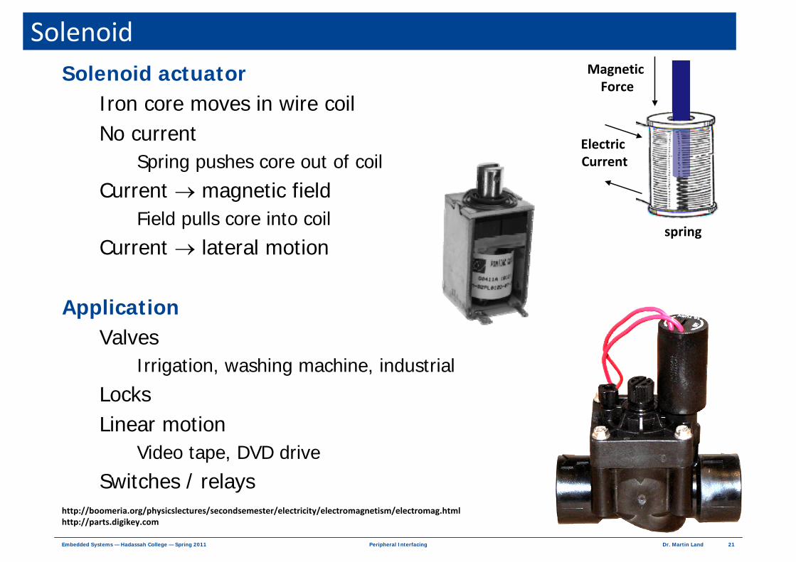
SolenoidSolenoid actuator
Iron core moves in wire coilNo current
Spring pushes core out of coil
Current → magnetic fieldField pulls core into coil
Current → lateral motion
ApplicationValves
Irrigation, washing machine, industrial
LocksLinear motion
Video tape, DVD drive
Switches / relayshttp://boomeria.org/physicslectures/secondsemester/electricity/electromagnetism/electromag.htmlhttp://parts.digikey.com
Magnetic Force
spring
Electric Current
22Dr. Martin LandPeripheral InterfacingEmbedded Systems — Hadassah College — Spring 2011
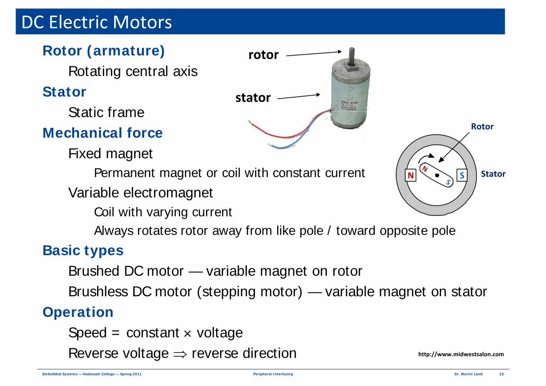
DC Electric MotorsRotor (armature)
Rotating central axis Stator
Static frame Mechanical force
Fixed magnet Permanent magnet or coil with constant current
Variable electromagnetCoil with varying currentAlways rotates rotor away from like pole / toward opposite pole
Basic typesBrushed DC motor — variable magnet on rotorBrushless DC motor (stepping motor) — variable magnet on stator
OperationSpeed = constant × voltageReverse voltage ⇒ reverse direction http://www.midwestsalon.com
rotor
stator
N SN
SStator
Rotor

23Dr. Martin LandPeripheral InterfacingEmbedded Systems — Hadassah College — Spring 2011
Brushed DC MotorStator
Fixed magnetic fieldRotor
Rotating coil magnetCoil winding
Front to backRight to left
BrushesConnect coils to current
CommutationGap between brushes
Swaps current direction when rotor rotates
Current always Enters on right side of coilLeaves on left side of coil
Field always opposes stator
N S
current stator
rotor
brushes
http://www.cvel.clemson.edu/auto/actuators/motors‐dc‐brushed.html

24Dr. Martin LandPeripheral InterfacingEmbedded Systems — Hadassah College — Spring 2011
Brushed DC Motor Rotation Phases

25Dr. Martin LandPeripheral InterfacingEmbedded Systems — Hadassah College — Spring 2011
Types of Brushed DC Motors
Stator field Permanent magnets
Advantages Most common Least complexLeast expensiveSpeed linear in voltage
DisadvantageMagnets weaken over time
Permanent magnet brushed DC (PMDC) motors
26Dr. Martin LandPeripheral InterfacingEmbedded Systems — Hadassah College — Spring 2011
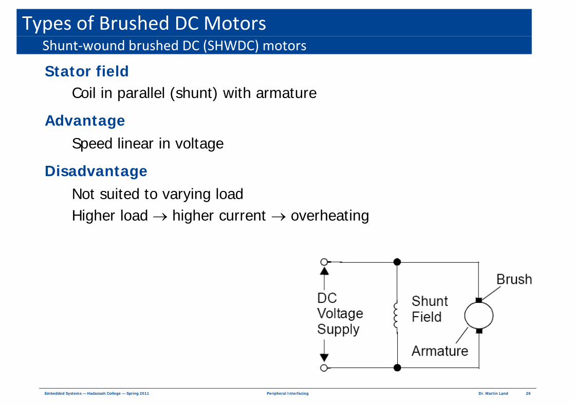
Types of Brushed DC Motors
Stator field Coil in parallel (shunt) with armature
Advantage Speed linear in voltage
DisadvantageNot suited to varying loadHigher load → higher current → overheating
Shunt‐wound brushed DC (SHWDC) motors

27Dr. Martin LandPeripheral InterfacingEmbedded Systems — Hadassah College — Spring 2011
Types of Brushed DC Motors
Stator field Coil in series with armature
Advantage Suited to varying loadHigher load → speed drops → higher current → higher torque
DisadvantageSpeed depends on load
Series‐wound brushed DC (SWDC) motors

28Dr. Martin LandPeripheral InterfacingEmbedded Systems — Hadassah College — Spring 2011
Control Circuits for DC MotorsPower
Supplied separately to MCU + motorMotor ← higher voltage / current than MCU
ControlMCU output signals
Sets motor speed + direction
Amplified by control circuit Power to motor determined by control signals
FeedbackMeasure motor speed → MCU MCU adjusts control signal
Responds to goal + measured result
Power
PowerSpeed
indication
Control
Feedback
MCU
PowerSupply
ControlCircuit
Motor
Control Circuit Output→MCU Output

29Dr. Martin LandPeripheral InterfacingEmbedded Systems — Hadassah College — Spring 2011
Elementary Control Theory
Physical stateVariables (functions of time) required to describe systemExamples — motor speed, direction, current, torqueNot all state variable are measured
Target stateDesired values of state variables
Physical modelMathematical description of system dynamics How system responds to external stimulusExample — relationship of voltage + motion for motor under load
ControlIndependently inputs to physical systemExternal stimulus applied by user
ControllabilityCan bring system to any desired state with appropriate control
Definitions
PhysicalState
PhysicalModel
measuredstatecontrol
Physical System

30Dr. Martin LandPeripheral InterfacingEmbedded Systems — Hadassah College — Spring 2011
FeedbackDevices
Amplifier A — amplifies Input → OutputSampler B — samples Output → SampleFeedback ⊕ — combines Sample + Control → Input
Feedback Sample of output state "fed back" to controllerControl loop
Control → sample → feedback (compare sample + target)
Control Input Output
Sample
http://en.wikipedia.org/wiki/Feedback

31Dr. Martin LandPeripheral InterfacingEmbedded Systems — Hadassah College — Spring 2011
Open Loop ControlOpen loop = no loop
ExampleSimple (ideal) permanent magnet motor
Model Voltage = k × Speed
Target state Speed = S0Control Voltage = k × S0
PhysicalState
PhysicalModel
measuredstatecontrol
Physical System
Calculator
MathematicalModel
targetstate
Controller
( ) ( ) ( )( )( ) ( )( )n+1 n n
n+1 n
state t = F state t , control t
control t = G target state t
32Dr. Martin LandPeripheral InterfacingEmbedded Systems — Hadassah College — Spring 2011
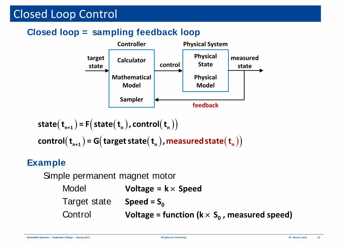
Closed Loop ControlClosed loop = sampling feedback loop
ExampleSimple permanent magnet motor
Model Voltage = k × Speed
Target state Speed = S0Control Voltage = function (k × S0 , measured speed)
PhysicalState
PhysicalModel
measuredstatecontrol
Physical System
Calculator
MathematicalModel
Sampler
targetstate
Controller
feedback
( ) ( ) ( )( )( ) ( ) ( )( )n+1 n n
n+1 n n
state t = F state t , control t
control t = meG tar asurget stat ed stae , te tt
33Dr. Martin LandPeripheral InterfacingEmbedded Systems — Hadassah College — Spring 2011
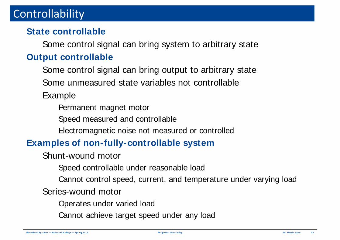
ControllabilityState controllable
Some control signal can bring system to arbitrary stateOutput controllable
Some control signal can bring output to arbitrary stateSome unmeasured state variables not controllableExample
Permanent magnet motorSpeed measured and controllableElectromagnetic noise not measured or controlled
Examples of non-fully-controllable systemShunt-wound motor
Speed controllable under reasonable loadCannot control speed, current, and temperature under varying load
Series-wound motorOperates under varied loadCannot achieve target speed under any load

34Dr. Martin LandPeripheral InterfacingEmbedded Systems — Hadassah College — Spring 2011
Abstraction Model for Brushed DC Motor
Motor parametersMechanical friction BElectrical resistance R
External sourceInput voltage VIN
Motor speedS rotations per minute
Back electromotive force (BEMF)Voltage generated by motor rotationDepends on speed of motorBEMF = V1 – V2 = k × S
MotorV1
V2
RVIN
IM
Parameters

35Dr. Martin LandPeripheral InterfacingEmbedded Systems — Hadassah College — Spring 2011
Abstraction Model for Brushed DC Motor
Steady state motion
General case
Ideal caseFriction B → 0 ⇒
( )IN M 1 2
d d d dV S I V V 0
dt dt dt dt= = = − =
Equations of motion
MotorV1
V2
RVIN
IM
( )
IN2
M IN2
1 2 IN2
kMotor speed S V
k RBB
Electric current I Vk RB
1BEMF V V k S V
1 RB/k
=−
=−
− = × =−
IN
M
1 2 IN
1Motor speed S V
kElectric current I 0
BEMF V V V
→
→− →

36Dr. Martin LandPeripheral InterfacingEmbedded Systems — Hadassah College — Spring 2011
Open Loop Brushed DC Motor Control
Ideal linear controlSpeed = VIN / k
Pulse Width Modulation (PWM)Control signal with PERIOD T and DUTY CYCLE D
Voltage averagingRotor coil ⇒ low pass filter
Unidirectional control
TDVmax
0
( )IN
max max
max
1 DD V T D 0 V
T TD
Speed Vk T
⎡ ⎤= × + − × = ×⎣ ⎦
= ××
Motor voltage = time average of control voltage V
control voltage VIN Motor

37Dr. Martin LandPeripheral InterfacingEmbedded Systems — Hadassah College — Spring 2011
Open Loop Brushed DC Motor Control
Ideal direction controlSpeed = (V1 – V2) / k
H-Bridge circuitMCU controls 4 independent output voltagesIdeal control abstraction
Controli = switchi for i = 1, 2, 3, 4
Bidirectional control
MotorV1
V2
Motor
Vsupply
Control1
Control2
Control3
Control4
V1
V2

38Dr. Martin LandPeripheral InterfacingEmbedded Systems — Hadassah College — Spring 2011
Open Loop Brushed DC Motor ControlControl signals to H‐bridge
Motor
Vsupply
Control1
Control2
Control3
Control4
V1
V2
ONOFFONOFFBrake
OFFOFFOFFOFFCoast
OFFONONOFFReverse
ONOFFOFFONForward
CTRL4CTRL3CTRL2CTRL1
Motor
Vsupply
Control1
Control2
Control3
Control4
V1
V2
Motor
Vsupply
Control1
Control2
Control3
Control4
V1
V2
Motor
Vsupply
Control1
Control2
Control3
Control4
V1
V2
Forward
Reverse
Coast
Brake

39Dr. Martin LandPeripheral InterfacingEmbedded Systems — Hadassah College — Spring 2011
Closed Loop Brushed DC Motor Control
Optical encoderSlotted wheel attached to motorLED → slotted wheel → photo transistorFrequency of light pulses → motor speed
Hall effect sensorMagnets on wheel attached to motorSensor generates pulse when magnet passes
Feedback sensors
Hall effect
Metal conductor in magnetic field
Current flows through conductor
Metal generates voltage
Voltage ⊥ current ⊥ fieldhttp://en.wikipedia.org/wiki/Hall_effect
40Dr. Martin LandPeripheral InterfacingEmbedded Systems — Hadassah College — Spring 2011
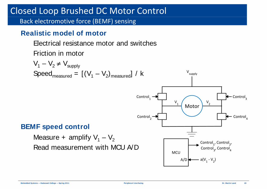
Closed Loop Brushed DC Motor Control
Realistic model of motorElectrical resistance motor and switches Friction in motor V1 – V2 ≠ Vsupply
Speedmeasured = [(V1 – V2)measured] / k
BEMF speed controlMeasure + amplify V1 – V2
Read measurement with MCU A/D
Back electromotive force (BEMF) sensing
Motor
Vsupply
Control1
Control2
Control3
Control4
MCU
Control1, Control
2,
Control3, Control
4
A/D a(V1 ‐ V
2)
V1
V2

41Dr. Martin LandPeripheral InterfacingEmbedded Systems — Hadassah College — Spring 2011
STMicroelectronics L293D Dual H‐BridgeElectrical connections
VS Motor supply voltage VSS Logic supply voltageGND Ground
Truth table
HHH
LHL
ZLH
ZLL
OutputEnableInput
Z = high impedance = equivalent to disconnected
10 V
Example5 V
Ground Ground
motorA
BE
Coastxx0
1
1
1
1
E
Brake11
Reverse10
Forward01
Brake00
MotorBA

42Dr. Martin LandPeripheral InterfacingEmbedded Systems — Hadassah College — Spring 2011
Brushless DC MotorsCommon applications
Automated machines, printers, volumetric pumpsAdvantages
Brushless Fewer failures
No electrical arcs — undesirable / dangerous in some environments
Speed independent of load (< torque rating for motor)
Open loop positioning Move in quantized steps
Position of rotor known without feedback mechanism
Holding Torque Can hold rotor stationary
Excellent response Controllable start, stop, reverse

43Dr. Martin LandPeripheral InterfacingEmbedded Systems — Hadassah College — Spring 2011
Types of Stepping MotorVariable reluctance motor
Soft iron rotor with teethTeeth attracted to magnetic coils on stator
Permanent magnet motorRotor constructed from magnetic stripsAttracted / repulsed by magnetic coils on statorWiring types
Unipolar winding — 3 contacts per coilBipolar winding — 2 contacts per coilBifilar winding — twin coils in parallel
Hybrid stepping motorCombines aspects of permanent magnet and variable reluctance
www.solarbotics.net/library/pdflib/pdf/motorbas.pdf

44Dr. Martin LandPeripheral InterfacingEmbedded Systems — Hadassah College — Spring 2011
Variable Reluctance Motor — 1
Voltage to A / A' Voltage to D / D' Voltage to C / C'
Voltage to B / B' Voltage to A / A' Voltage to D / D'
45Dr. Martin LandPeripheral InterfacingEmbedded Systems — Hadassah College — Spring 2011
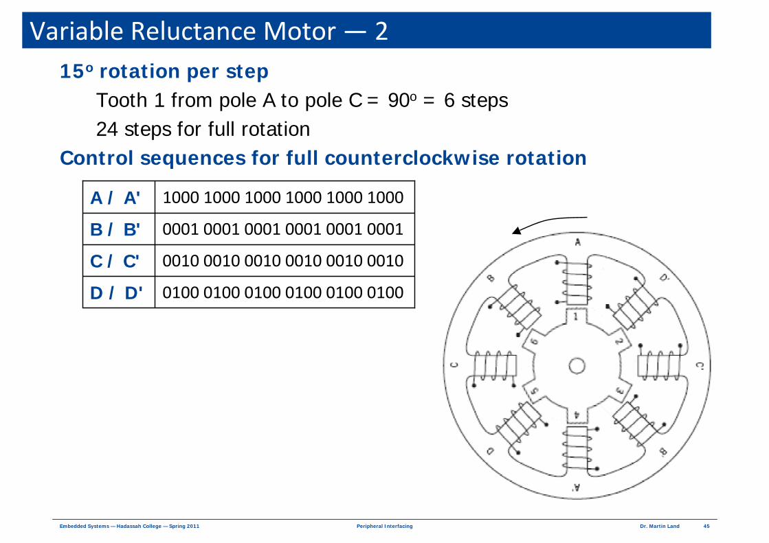
Variable Reluctance Motor — 215o rotation per step
Tooth 1 from pole A to pole C = 90o = 6 steps24 steps for full rotation
Control sequences for full counterclockwise rotation
0100 0100 0100 0100 0100 0100D / D'
0010 0010 0010 0010 0010 0010C / C'
0001 0001 0001 0001 0001 0001B / B'
1000 1000 1000 1000 1000 1000A / A'
46Dr. Martin LandPeripheral InterfacingEmbedded Systems — Hadassah College — Spring 2011
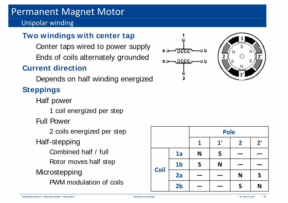
Permanent Magnet Motor
Two windings with center tapCenter taps wired to power supply Ends of coils alternately grounded
Current direction Depends on half winding energized
SteppingsHalf power
1 coil energized per step
Full Power2 coils energized per step
Half-steppingCombined half / fullRotor moves half step
MicrosteppingPWM modulation of coils
Unipolar winding
Pole
Coil
NS——2b
SN——2a
——NS1b
——SN1a
2 2'1'1
1
1'
2 2'

47Dr. Martin LandPeripheral InterfacingEmbedded Systems — Hadassah College — Spring 2011
Permanent Magnet MotorUnipolar winding steppings
001110000011100000111000
000000111000001110000011
000011100000111000001110
111000001110000011100000
Half‐SteppingFull PowerHalf Power
011001100110
100110011001
001100110011
110011001100
0100010001002b
0001000100012a
0010001000101b
1000100010001a
48Dr. Martin LandPeripheral InterfacingEmbedded Systems — Hadassah College — Spring 2011
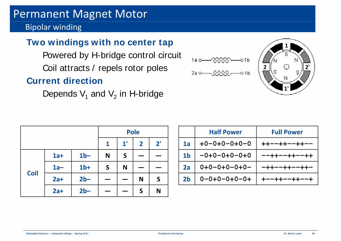
Permanent Magnet Motor
Two windings with no center tapPowered by H-bridge control circuitCoil attracts / repels rotor poles
Current direction Depends V1 and V2 in H-bridge
Bipolar winding
2b–
2b–
1b+
1b–
Pole
Coil
NS——2a+
SN——2a+
——NS1a–
——SN1a+
2 2'1'1
1
1'
2 2'
Full PowerHalf Power
+--++--++--+
-++--++--++-
--++--++--++
++--++--++--
0-0+0-0+0-0+2b
0+0-0+0-0+0-2a
-0+0-0+0-0+01b
+0-0+0-0+0-01a

49Dr. Martin LandPeripheral InterfacingEmbedded Systems — Hadassah College — Spring 2011
MicrosteppingProblems with single stepping
Jerky motor movement at low speedNoisy
Advantage of microstepping Smoother transition
Increase step resolution Reduce noise
Microstepping techniquePulse width modulate coils voltages
Duty cycle of signal to coil lowered Duty cycle of signal to next winding raised
Sine-cosine microstepping
1 MAXmicrosteps
2 MAXmicrosteps
π θI I sin
2 N
π θI I cos
2 N
⎛ ⎞= ⎜ ⎟⎜ ⎟
⎝ ⎠⎛ ⎞
= ⎜ ⎟⎜ ⎟⎝ ⎠ Nmicrosteps = microsteps per step
I1
I2
θ = angular position of rotor
50Dr. Martin LandPeripheral InterfacingEmbedded Systems — Hadassah College — Spring 2011
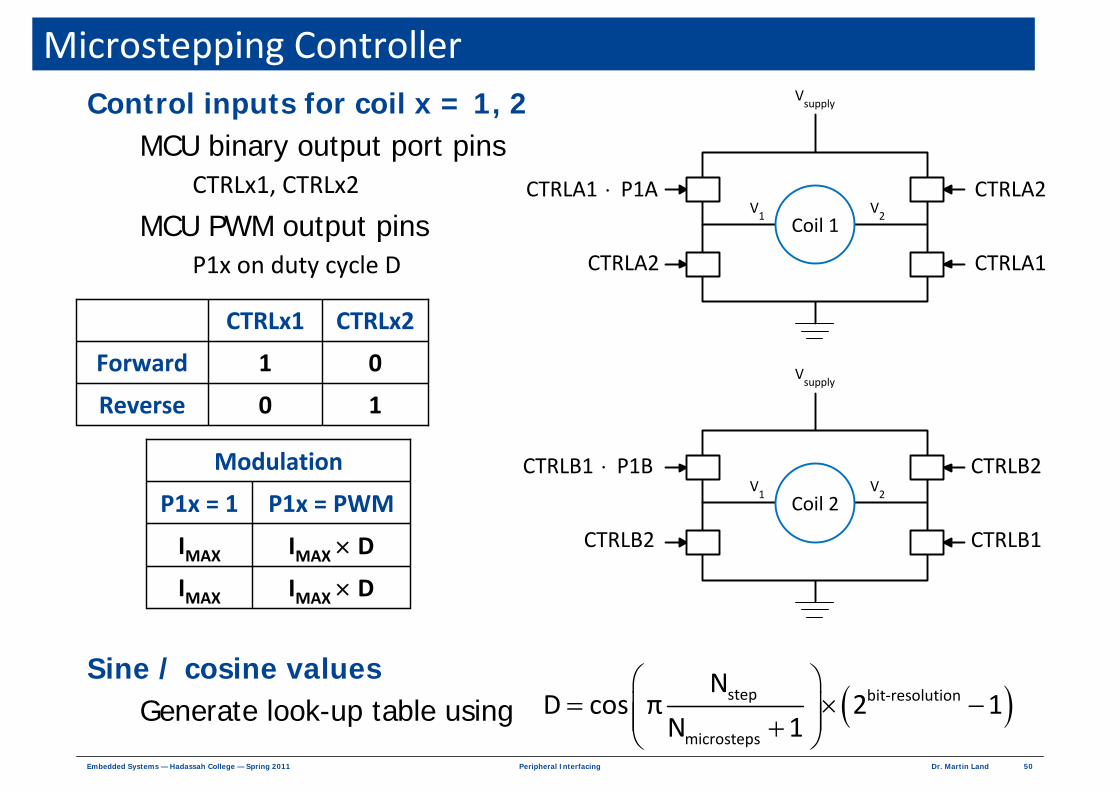
Microstepping ControllerControl inputs for coil x = 1, 2
MCU binary output port pinsCTRLx1, CTRLx2
MCU PWM output pinsP1x on duty cycle D
Sine / cosine valuesGenerate look-up table using
Coil 1
Vsupply
V1
V2
Coil 2
Vsupply
V1
V2
CTRLA1 P1A⋅
CTRLA2
CTRLA2
CTRLA1
CTRLB1 P1B⋅
CTRLB2
CTRLB2
CTRLB1
10Reverse
01Forward
CTRLx2CTRLx1
Modulation
IMAX × DIMAX
IMAX × DIMAX
P1x = PWMP1x = 1
( )step bit‐resolution
microsteps
ND cos π 2 1
N 1
⎛ ⎞= × −⎜ ⎟⎜ ⎟+⎝ ⎠