Lesson 17: Slope Deflection analysis : Frames with side sway°NŞ314/icerik/m3l17_The Slope... ·...
21
Module 3 Analysis of Statically Indeterminate Structures by the Displacement Method
Transcript of Lesson 17: Slope Deflection analysis : Frames with side sway°NŞ314/icerik/m3l17_The Slope... ·...
Module 3
Analysis of Statically Indeterminate
Structures by the Displacement Method
Lesson 17
The Slope-Deflection Method: Frames with
Sidesway
Instructional Objectives After reading this chapter the student will be able to 1. Derive slope-deflection equations for the frames undergoing sidesway. 2. Analyse plane frames undergoing sidesway. 3, Draw shear force and bending moment diagrams. 4. Sketch deflected shape of the plane frame not restrained against sidesway. 17.1 Introduction In this lesson, slope-deflection equations are applied to analyse statically indeterminate frames undergoing sidesway. As stated earlier, the axial deformation of beams and columns are small and are neglected in the analysis. In the previous lesson, it was observed that sidesway in a frame will not occur if
1. They are restrained against sidesway. 2. If the frame geometry and the loading are symmetrical.
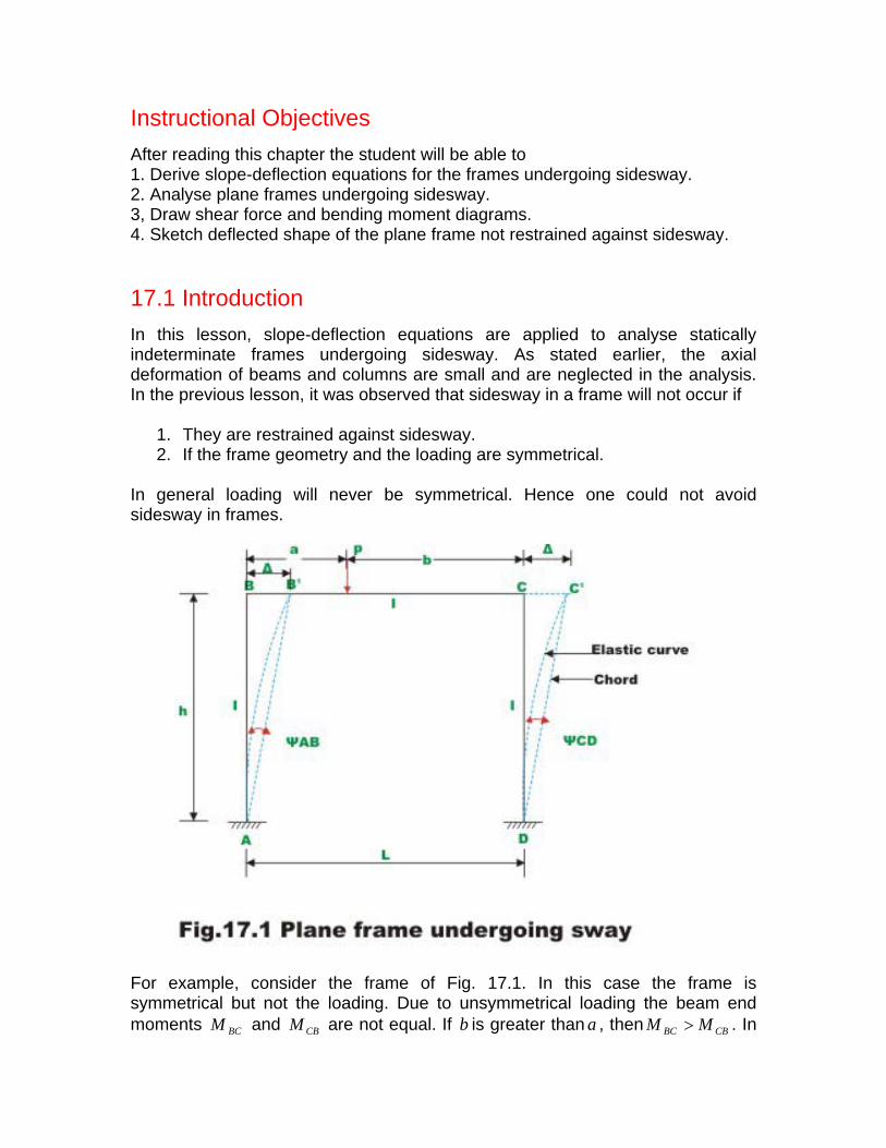
In general loading will never be symmetrical. Hence one could not avoid sidesway in frames.
For example, consider the frame of Fig. 17.1. In this case the frame is symmetrical but not the loading. Due to unsymmetrical loading the beam end moments and are not equal. If is greater than , then . In BCM CBM b a CBBC MM >
such a case joint B andC are displaced toward right as shown in the figure by an unknown amountΔ . Hence we have three unknown displacements in this frame: rotations CB θθ , and the linear displacementΔ . The unknown joint rotations
Bθ and Cθ are related to joint moments by the moment equilibrium equations. Similarly, when unknown linear displacement occurs, one needs to consider force-equilibrium equations. While applying slope-deflection equation to columns
in the above frame, one must consider the column rotation ⎟⎠⎞
⎜⎝⎛ Δ=
hψ as
unknowns. It is observed that in the column AB , the end B undergoes a linear displacement with respect to endΔ A . Hence the slope-deflection equation for column AB is similar to the one for beam undergoing support settlement. However, in this case is unknown. For each of the members we can write the following slope-deflection equations.
Δ
[ ABBAFABAB ]MM ψθθ 322
−++=hEI where
hABΔ
−=ψ
ABψ is assumed to be negative as the chord to the elastic curve rotates in the
clockwise directions.
[ ]ABABFBABA h
EIMM ψθθ 322−++=
[ ]CBFBCBC h
EIMM θθ ++= 22
[ ]BCFCBCB h
EIMM θθ ++= 22
[ ]CDDCFCDCD h
EIMM ψθθ 322−++=
hCDΔ
−=ψ
[ CDCDFDCDC h
EIMM ψθθ 322−++= ] (17.1)
As there are three unknowns ( CB θθ , andΔ ), three equations are required to evaluate them. Two equations are obtained by considering the moment equilibrium of joint B and C respectively.
00 =+⇒=∑ BCBAB MMM (17.2a)
00 =+⇒=∑ CDCBC MMM (17.2b) Now consider free body diagram of the frame as shown in Fig. 17.2. The horizontal shear force acting at A and B of the column AB is given by
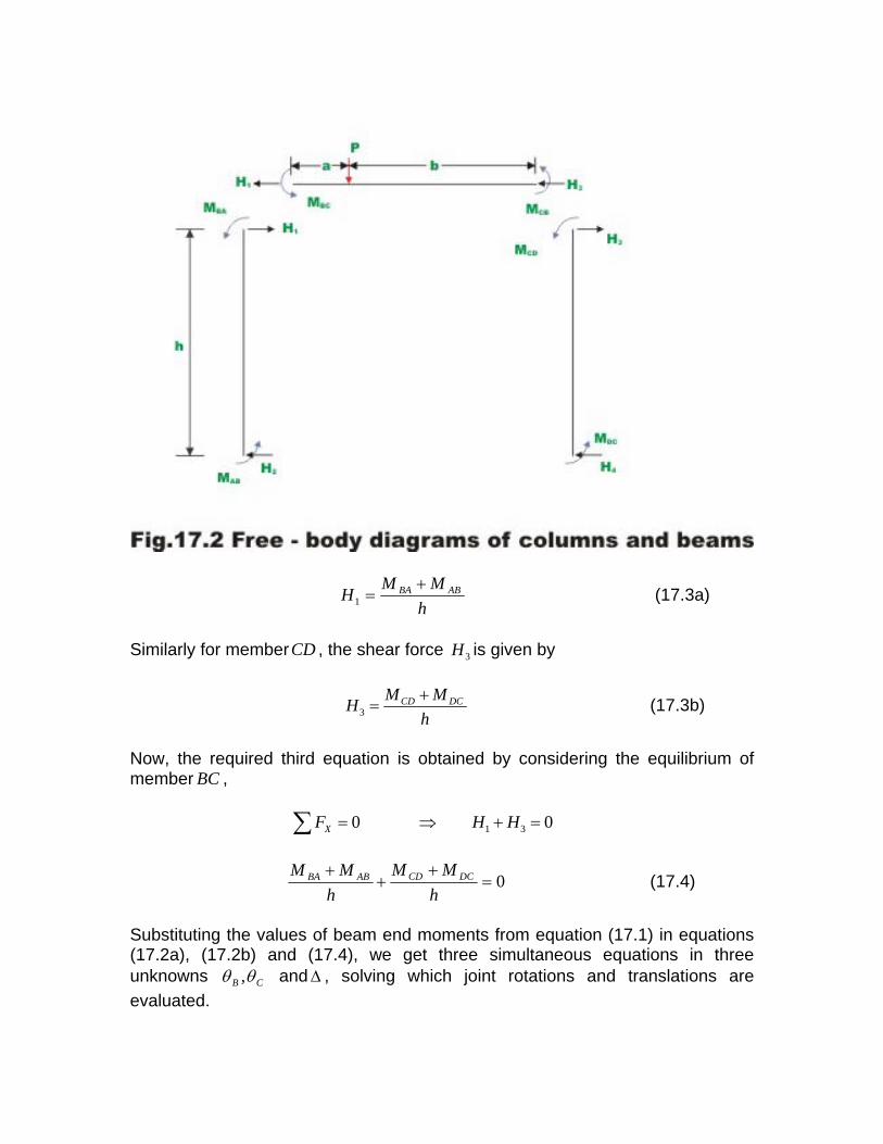
hMMH ABBA +=1 (17.3a)
Similarly for memberCD , the shear force is given by 3H
3CD DCM MH
h+
= (17.3b)
Now, the required third equation is obtained by considering the equilibrium of member , BC
1 30 0XF H= ⇒ +∑ H =
0=+
++
hMM
hMM DCCDABBA (17.4)
Substituting the values of beam end moments from equation (17.1) in equations (17.2a), (17.2b) and (17.4), we get three simultaneous equations in three unknowns CB θθ , and , solving which joint rotations and translations are evaluated.
Δ

Knowing joint rotations and translations, beam end moments are calculated from slope-deflection equations. The complete procedure is explained with a few numerical examples.
Example 17.1
Analyse the rigid frame as shown in Fig. 17.3a. Assume EI to be constant for all members. Draw bending moment diagram and sketch qualitative elastic curve.
Solution In the given problem, joints B and rotate and also translate by an amountC Δ . Hence, in this problem we have three unknown displacements (two rotations and one translation) to be evaluated. Considering the kinematically determinate structure, fixed end moments are evaluated. Thus,
.0;0;.10;.10;0;0 ==−=+=== FDC
FCD
FCB
FBC
FBA
FAB MMmkNMmkNMMM (1)
The ends A and are fixed. Hence, D .0== DA θθ Joints B and translate by the same amount . Hence, chord to the elastic curve
CΔ 'AB and ' rotates by an
amount (see Fig. 17.3b) DC
3Δ
−== CDAB ψψ (2)
Chords of the elastic curve 'AB and ' rotate in the clockwise direction; hence
DCABψ and CDψ are taken as negative.
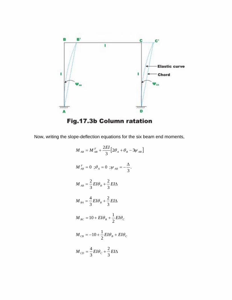
Now, writing the slope-deflection equations for the six beam end moments,
[ ]ABBAFABAB
EIMM ψθθ 323
2−++=
.3
;0;0 Δ−=== ABA
FABM ψθ
Δ+= EIEIM BAB 32
32 θ
Δ+= EIEIM BBA 32
34 θ
CBBC EIEIM θθ2110 ++=
CBCB EIEIM θθ ++−=2110
Δ+= EIEIM CCD 32
34 θ

Δ+= EIEIM CDC 32
32 θ (3)
Now, consider the joint equilibrium of B andC (vide Fig. 17.3c).
00 =+⇒=∑ BCBAB MMM (4) (5) 00 =+⇒=∑ CDCBC MMM
The required third equation is written considering the horizontal equilibrium of the entire frame (vide Fig. 17.3d). ..ei ∑ = 0XF 010 21 =−+− HH 1021 =+⇒ HH . (6)

Considering the equilibrium of the column AB andCD , yields
31ABBA MMH +
=
and
32
DCCD MMH
+= (7)
The equation (6) may be written as,
30=+++ DCCDABBA MMMM (8) Substituting the beam end moments from equation (3) in equations (4), (5) and (6)
10667.05.0333.2 −=Δ++ EIEIEI CB θθ (9)
10667.05.0333.2 =Δ++ EIEIEI BC θθ (10)

303822 =Δ++ EIEIEI CB θθ (11)
Equations (9), (10) and (11) indicate symmetry and this fact may be noted. This may be used as the check in deriving these equations. Solving equations (9), (10) and (11),
355.1;572.9 =−= CB EIEI θθ and 417.17=ΔEI . Substituting the values of CB EIEI θθ , and ΔEI in the slope-deflection equation (3), one could calculate beam end moments. Thus,
5.23 kN.m (counterclockwise)ABM =
1.14 kN.m(clockwise)BAM = −
1.130 kN.mBCM =
13.415 kN.mCBM = −
13.406 kN.mCDM =
12.500 kN.mDCM = . The bending moment diagram for the frame is shown in Fig. 17.3 e. And the elastic curve is shown in Fig 17.3 f. the bending moment diagram is drawn on the compression side. Also note that the vertical hatching is used to represent bending moment diagram for the horizontal members (beams).


Example 17.2
Analyse the rigid frame as shown in Fig. 17.4a and draw the bending moment diagram. The moment of inertia for all the members is shown in the figure. Neglect axial deformations.
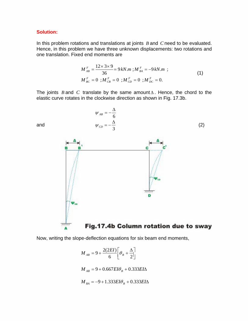
Solution: In this problem rotations and translations at joints B and need to be evaluated. Hence, in this problem we have three unknown displacements: two rotations and one translation. Fixed end moments are
C
.0;0;0;0
;.9;.936
9312
====
−==××
=
FDC
FCD
FCB
FBC
FBA
FAB
MMMM
mkNMmkNM (1)
The joints B and translate by the same amountC Δ . Hence, the chord to the elastic curve rotates in the clockwise direction as shown in Fig. 17.3b.
6Δ
−=ABψ
and 3Δ
−=CDψ (2)
Now, writing the slope-deflection equations for six beam end moments,
⎥⎦⎤
⎢⎣⎡ Δ
++=26
)2(29 BABEIM θ
Δ++= EIEIM BAB 333.0667.09 θ
Δ++−= EIEIM BBA 333.0333.19 θ

CBBC EIEIM θθ 5.0+=
CBCB EIEIM θθ += 5.0
Δ+= EIEIM CCD 667.0333.1 θ
Δ+= EIEIM CDC 667.0667.0 θ (3) Now, consider the joint equilibrium of B andC .
00 =+⇒=∑ BCBAB MMM (4)
00 =+⇒=∑ CDCBC MMM (5)
The required third equation is written considering the horizontal equilibrium of the entire frame. Considering the free body diagram of the member (vide Fig. 17.4c),
BC
021 =+ HH .
(6)
The forces and are calculated from the free body diagram of column 1H 2HAB andCD . Thus,
661
ABBA MMH ++−=
and
32
DCCD MMH
+= (7)
Substituting the values of and into equation (6) yields, 1H 2H
3622 =+++ DCCDABBA MMMM (8) Substituting the beam end moments from equation (3) in equations (4), (5) and (8), yields
9333.05.0333.2 =Δ++ EIEIEI CB θθ
0667.05.0333.2 =Δ++ EIEIEI BC θθ
36333.342 =Δ++ EIEIEI CB θθ (9) Solving equations (9), (10) and (11),
88.4;76.2 −== CB EIEI θθ and 00.15=ΔEI . Substituting the values of CB EIEI θθ , and ΔEI in the slope-deflection equation (3), one could calculate beam end moments. Thus,
15.835 kN.m (counterclockwise)ABM = 0.325 kN.m(clockwise)BAM = −
0.32 kN.mBCM = 3.50 kN.mCBM = −
3.50 kN.mCDM = 6.75 kN.mDCM = .
The bending moment diagram for the frame is shown in Fig. 17.4 d.


Example 17.3 Analyse the rigid frame shown in Fig. 17.5 a. Moment of inertia of all the members are shown in the figure. Draw bending moment diagram.
Under the action of external forces, the frame gets deformed as shown in Fig. 17.5b. In this figure, chord to the elastic curve are shown by dotted line. 'BB is perpendicular to AB and is perpendicular to . The chords to the elastic "CC DC
curve "AB rotates by an angle ABψ , rotates by ""CB BCψ and rotates by DC
CDψ as shown in figure. Due to symmetry, ABCD ψψ = . From the geometry of the figure,
ABABAB LL
BB 1" Δ−==ψ
But
αcos1Δ
=Δ
Thus,
5cosΔ
−=Δ
−=α
ψAB
AB L
5Δ
−=CDψ
5tan
2tan2
22 Δ
=Δ=Δ
=Δ
= ααψ BC (1)
We have three independent unknowns for this problem CB θθ , and . The ends Δ
A and are fixed. Hence, D .0== DA θθ Fixed end moments are,
.0;0;.50.2;.50.2;0;0 ==−=+=== FDC
FCD
FCB
FBC
FBA
FAB MMmkNMmkNMMM
Now, writing the slope-deflection equations for the six beam end moments,
[ ]ABAABIEM ψθ 3
1.5)2(2
−=
Δ+= EIEIM BAB 471.0784.0 θ Δ+= EIEIM BBA 471.0568.1 θ
Δ−++= EIEIEIM CBBC 6.025.2 θθ Δ−++−= EIEIEIM CBBC 6.025.2 θθ
Δ+= EIEIM CCD 471.0568.1 θ Δ+= EIEIM CDC 471.0784.0 θ (2)
Now, considering the joint equilibrium of B andC , yields
00 =+⇒=∑ BCBAB MMM
5.2129.0568.3 −=Δ−+ EIEIEI CB θθ (3)
00 =+⇒=∑ CDCBC MMM
5.2129.0568.3 =Δ−+ EIEIEI BC θθ (4)
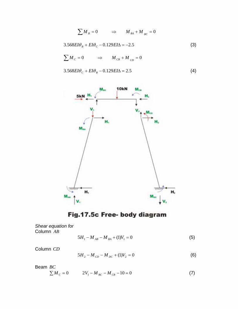
Shear equation for Column AB
0)1(5 11 =+−− VMMH BAAB (5)
Column CD0)1(5 22 =+−− VMMH DCCD (6)
Beam BC
01020 1 =−−−=∑ CBBCC MMVM (7)

∑ =+= 50 21 HHFX (8)
∑ =−−= 0100 21 VVFY (9)
From equation (7), 2
101
++= CBBC MM
V
From equation (8), 21 5 HH −=
From equation (9), 102
101012 −
++=−= CBBC MM
VV
Substituting the values of and in equations (5) and (6), 11, HV 2V
0221060 2 =++−−− CBBCBAAB MMMMH (10) 0221010 2 =++−−+− CBBCDCCD MMMMH (11)
Eliminating in equation (10) and (11), 2H
25=−−+++ CBBCDCCDBAAB MMMMMM (12) Substituting the values of in (12) we get the required third equation. Thus,
DCCDBAAB MMMM ,,,
+Δ+ EIEI B 471.0784.0 θ +Δ+ EIEI B 471.0568.1 θ +Δ+ EIEI C 471.0568.1 θ
Δ+ EIEI C 471.0784.0 θ -( Δ−++ EIEIEI CB 6.025.2 θθ )-( Δ−++− EIEIEI CB 6.025.2 θθ ) 25=
Simplifying,
25084.3648.0648.0 =Δ+−− EIEIEI BC θθ (13) Solving simultaneously equations (3) (4) and (13), yields
205.1;741.0 =−= CB EIEI θθ and 204.8=ΔEI . Substituting the values of CB EIEI θθ , and ΔEI in the slope-deflection equation (3), one could calculate beam end moments. Thus,
3.28 kN.mABM =
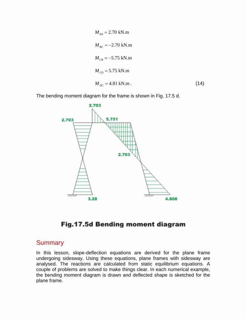
2.70 kN.mBAM =
2.70 kN.mBCM = −
5.75 kN.mCBM = −
5.75 kN.mCDM =
4.81 kN.mDCM = . (14) The bending moment diagram for the frame is shown in Fig. 17.5 d.
Summary In this lesson, slope-deflection equations are derived for the plane frame undergoing sidesway. Using these equations, plane frames with sidesway are analysed. The reactions are calculated from static equilibrium equations. A couple of problems are solved to make things clear. In each numerical example, the bending moment diagram is drawn and deflected shape is sketched for the plane frame.


![Slope Deflection Method[1]](https://static.fdocuments.us/doc/165x107/5571fe4449795991699b02b5/slope-deflection-method1.jpg)