
Lesson 1, slide 1, picture 1 - Pedestrian & Bicycle ... · Web viewPicture shows classic American...
52
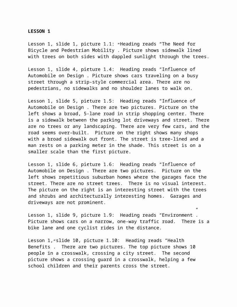
LESSON 1 Lesson 1, slide 1, picture 1.1: Heading reads “The Need for Bicycle and Pedestrian Mobility”. Picture shows sidewalk lined with trees on both sides with dappled sunlight through the trees. Lesson 1, slide 4, picture 1.4: Heading reads “Influence of Automobile on Design”. Picture shows cars traveling on a busy street through a strip-style commercial area. There are no pedestrians, no sidewalks and no shoulder lanes to walk on. Lesson 1, slide 5, picture 1.5: Heading reads “Influence of Automobile on Design”. There are two pictures. Picture on the left shows a broad, 5-lane road in strip shopping center. There is a sidewalk between the parking lot driveways and street. There are no trees or any landscaping. There are very few cars, and the road seems over-built. Picture on the right shows many shops with a broad sidewalk out front. The street is tree-lined and a man rests on a parking meter in the shade. This street is on a smaller scale than the first picture. Lesson 1, slide 6, picture 1.6: Heading reads “Influence of Automobile on Design”. There are two pictures. Picture on the left shows repetitious suburban homes where the garages face the street. There are no street trees. There is no visual interest. The picture on the right is an interesting street with the trees and shrubs and architecturally interesting homes. Garages and driveways are not prominent. Lesson 1, slide 9, picture 1.9: Heading reads “Environment”. Picture shows cars on a narrow, one-way traffic road. There is a bike lane and one cyclist rides in the distance. Lesson 1, slide 10, picture 1.10: Heading reads “Health Benefits”. There are two pictures. The top picture shows 10 people in a crosswalk, crossing a city street. The second picture shows a crossing guard in a crosswalk, helping a few school children and their parents cross the street.
Transcript of Lesson 1, slide 1, picture 1 - Pedestrian & Bicycle ... · Web viewPicture shows classic American...
LESSON 1
Lesson 1, slide 1, picture 1.1: Heading reads “The Need for Bicycle and Pedestrian Mobility”. Picture shows sidewalk lined with trees on both sides with dappled sunlight through the trees.
Lesson 1, slide 4, picture 1.4: Heading reads “Influence of Automobile on Design”. Picture shows cars traveling on a busy street through a strip-style commercial area. There are no pedestrians, no sidewalks and no shoulder lanes to walk on.
Lesson 1, slide 5, picture 1.5: Heading reads “Influence of Automobile on Design”. There are two pictures. Picture on the left shows a broad, 5-lane road in strip shopping center. There is a sidewalk between the parking lot driveways and street. There are no trees or any landscaping. There are very few cars, and the road seems over-built. Picture on the right shows many shops with a broad sidewalk out front. The street is tree-lined and a man rests on a parking meter in the shade. This street is on a smaller scale than the first picture.
Lesson 1, slide 6, picture 1.6: Heading reads “Influence of Automobile on Design”. There are two pictures. Picture on the left shows repetitious suburban homes where the garages face the street. There are no street trees. There is no visual interest. The picture on the right is an interesting street with the trees and shrubs and architecturally interesting homes. Garages and driveways are not prominent.
Lesson 1, slide 9, picture 1.9: Heading reads “Environment”. Picture shows cars on a narrow, one-way traffic road. There is a bike lane and one cyclist rides in the distance.
Lesson 1, slide 10, picture 1.10: Heading reads “Health Benefits”. There are two pictures. The top picture shows 10 people in a crosswalk, crossing a city street. The second picture shows a crossing guard in a crosswalk, helping a few school children and their parents cross the street.
LESSON 2
Lesson 2, slide 1, picture 2.1: Heading reads “Bicycling and Walking in the United States Today”. The picture shows a tree-lined downtown street with a bike lane and four bicyclists riding in the bike lane in the direction of the camera.
Lesson 2, slide 3, picture 2.3: Heading reads “2001 National Household Travel Survey Data”. Graphic shows a pie chart that evaluates mode splits over a 28-day period. 48.9% of those surveyed traveled via personal vehicle with multiple occupants. 37.6% rode in personal vehicles with one occupant. 1.5% of those surveyed traveled by mass transit. 1.7% traveled via school bus. 8.6% of the respondents walked, and the remaining 1.7% respondents chose other modes not already listed.
Lesson 2, slide 6, picture 2.6: Heading reads “Distance/Time”. The picture shows an aerial view of a suburban cul-de-sac neighborhood. The development is surrounded by a large forest area. There are no pedestrian connections between the ends of the cul de sacs, and one would have a long way to walk or bike to the main street.
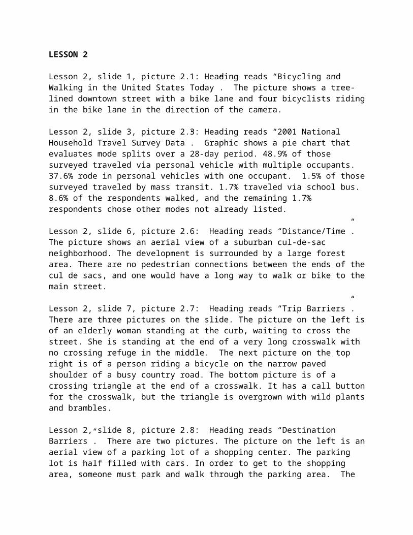
Lesson 2, slide 7, picture 2.7: Heading reads “Trip Barriers”. There are three pictures on the slide. The picture on the left is of an elderly woman standing at the curb, waiting to cross the street. She is standing at the end of a very long crosswalk with no crossing refuge in the middle. The next picture on the top right is of a person riding a bicycle on the narrow paved shoulder of a busy country road. The bottom picture is of a crossing triangle at the end of a crosswalk. It has a call button for the crosswalk, but the triangle is overgrown with wild plants and brambles.
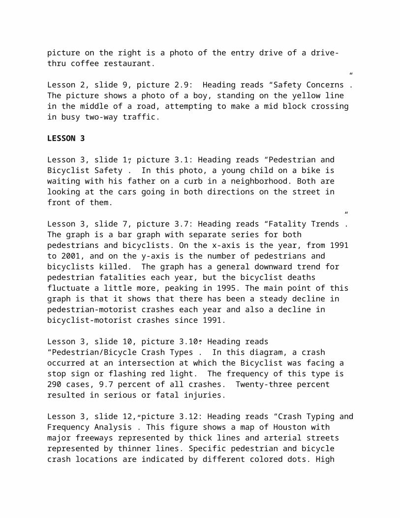
Lesson 2, slide 8, picture 2.8: Heading reads “Destination Barriers”. There are two pictures. The picture on the left is an aerial view of a parking lot of a shopping center. The parking lot is half filled with cars. In order to get to the shopping area, someone must park and walk through the parking area. The picture on the right is a photo of the entry drive of a drive-thru coffee restaurant.
Lesson 2, slide 9, picture 2.9: Heading reads “Safety Concerns”. The picture shows a photo of a boy, standing on the yellow line in the middle of a road, attempting to make a mid block crossing in busy two-way traffic.
LESSON 3
Lesson 3, slide 1, picture 3.1: Heading reads “Pedestrian and Bicyclist Safety”. In this photo, a young child on a bike is waiting with his father on a curb in a neighborhood. Both are looking at the cars going in both directions on the street in front of them.
Lesson 3, slide 7, picture 3.7: Heading reads “Fatality Trends”. The graph is a bar graph with separate series for both pedestrians and bicyclists. On the x-axis is the year, from 1991 to 2001, and on the y-axis is the number of pedestrians and bicyclists killed. The graph has a general downward trend for pedestrian fatalities each year, but the bicyclist deaths fluctuate a little more, peaking in 1995. The main point of this graph is that it shows that there has been a steady decline in pedestrian-motorist crashes each year and also a decline in bicyclist-motorist crashes since 1991.
Lesson 3, slide 10, picture 3.10: Heading reads “Pedestrian/Bicycle Crash Types”. In this diagram, a crash occurred at an intersection at which the Bicyclist was facing a stop sign or flashing red light. The frequency of this type is 290 cases, 9.7 percent of all crashes. Twenty-three percent resulted in serious or fatal injuries.
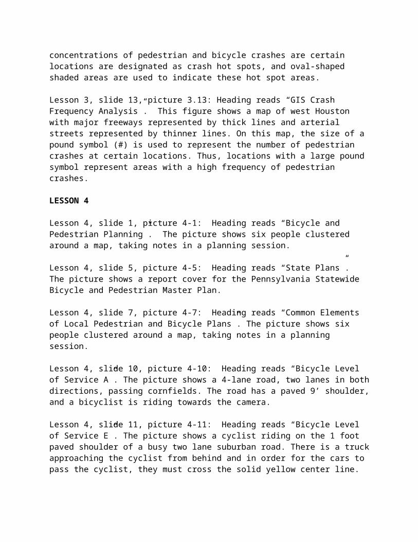
Lesson 3, slide 12, picture 3.12: Heading reads “Crash Typing and Frequency Analysis”. This figure shows a map of Houston with major freeways represented by thick lines and arterial streets represented by thinner lines. Specific pedestrian and bicycle crash locations are indicated by different colored dots. High concentrations of pedestrian and bicycle crashes are certain locations are designated as crash hot spots, and oval-shaped shaded areas are used to indicate these hot spot areas.
Lesson 3, slide 13, picture 3.13: Heading reads “GIS Crash Frequency Analysis”. This figure shows a map of west Houston with major freeways represented by thick lines and arterial streets
represented by thinner lines. On this map, the size of a pound symbol (#) is used to represent the number of pedestrian crashes at certain locations. Thus, locations with a large pound symbol represent areas with a high frequency of pedestrian crashes.
LESSON 4
Lesson 4, slide 1, picture 4-1: Heading reads “Bicycle and Pedestrian Planning”. The picture shows six people clustered around a map, taking notes in a planning session.
Lesson 4, slide 5, picture 4-5: Heading reads “State Plans”. The picture shows a report cover for the Pennsylvania Statewide Bicycle and Pedestrian Master Plan.
Lesson 4, slide 7, picture 4-7: Heading reads “Common Elements of Local Pedestrian and Bicycle Plans”. The picture shows six people clustered around a map, taking notes in a planning session.
Lesson 4, slide 10, picture 4-10: Heading reads “Bicycle Level of Service A”. The picture shows a 4-lane road, two lanes in both directions, passing cornfields. The road has a paved 9’ shoulder, and a bicyclist is riding towards the camera.
Lesson 4, slide 11, picture 4-11: Heading reads “Bicycle Level of Service E”. The picture shows a cyclist riding on the 1 foot paved shoulder of a busy two lane suburban road. There is a truck approaching the cyclist from behind and in order for the cars to pass the cyclist, they must cross the solid yellow center line.
Lesson 4, slide 12, picture 4-12: Heading reads: “Types of Maps”. There is a graphic picture of a GIS drawing of the Lancaster County Prioritized Bicycle System.
LESSON 5
Lesson 5, slide 1, picture 5-1: Heading reads: “Land Use Regulations to Encourage Nonmotorized Travel”. There is an aerial photograph of a suburban development. The streets curve and snake through the landscape, and by design, they do not lend themselves to easy pedestrian movement.
Lesson 5, slide 6, picture 5-6: Heading reads: “Building Orientation”. Picture shows an 8-12’ sidewalk in front of stores. There are trees, large flower pots, newspaper boxes and park benches, narrowing the walking area. There is a child on a scooter and three women holding coffee cups and chatting outside one of the shops.
Lesson 5, slide 7, picture 5-7: Heading reads: “On-Site Circulation”. The picture shows a sunken patio area with café tables in what looks like a new shopping center. Parking does not come right up to the doors of the shops. There is a covered pergola area enclosing the patio, and the shop entrances are under this covered area. The picture shows numerous groups of people sitting on a wall separation of the patio, and others seated around tables.
Lesson 5, slide 8, picture 5-8: Heading reads: “Development Connections”. The picture shows a new-looking shopping development with a gateway structure between buildings. By creating a landmark the connection to the parking area is easier to find.
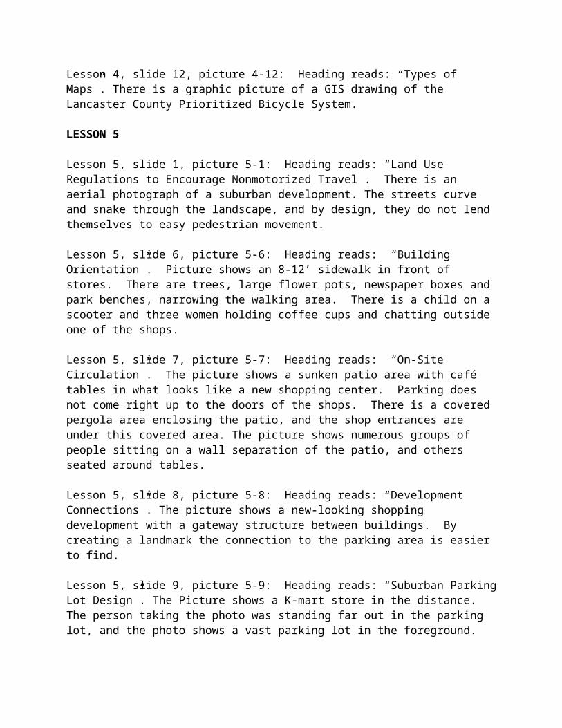
Lesson 5, slide 9, picture 5-9: Heading reads: “Suburban Parking Lot Design”. The Picture shows a K-mart store in the distance. The person taking the photo was standing far out in the parking lot, and the photo shows a vast parking lot in the foreground.
Lesson 5, slide 10, picture 5-10: Heading reads: “Creative Parking Lot Design”. The picture shows a tree lined sidewalk that is lavishly landscaped on both sides. The sidewalk area forms a buffer between what looks to be the roadway into a commercial area on the left and a parking lot on the right.
Lesson 5, slide 12, picture 5-12: Heading reads: “Interconnectivity”. The picture shows an aerial view drawing of a neighborhood with a variety of different house types and sizes. Streets are connected in a variety of ways. There are few cul-de-sacs. There is always more than one way to enter or exit a street.
Lesson 5, slide 13, picture 5-13: Heading reads: “Missed Connections”. Picture shows a very wide suburban street with the backs of the neighborhood houses facing the street. In the foreground of the picture, there is a sidewalk with a mid-block crossing that ends short or reaching the neighborhood.
Lesson 5, slide 14, picture 5-14: Heading reads: “Cul-de-sacs”. Picture shows houses facing the cul-de-sac. There is a sidewalk off the end of the cul-de-sac that leads to another cul-de-sac, allowing pedestrian traffic flow.
Lesson 5, slide 15, picture 5-15: Heading reads: “Trail Connections”. Picture shows a tree lined brick paved path connecting one street in a neighborhood with another street at the other end. There are bollards in the center of the path at each entrance, keeping cars from cutting through. However, bikes and pedestrians can easily pass.
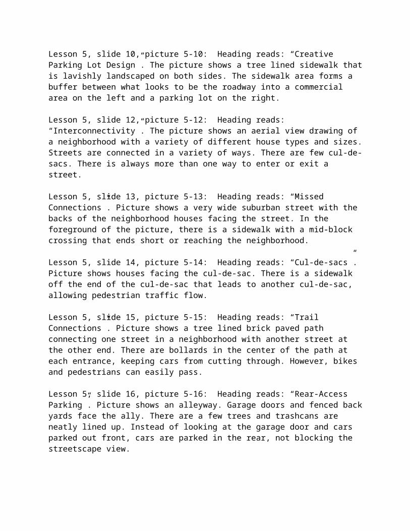
Lesson 5, slide 16, picture 5-16: Heading reads: “Rear-Access Parking”. Picture shows an alleyway. Garage doors and fenced back yards face the ally. There are a few trees and trashcans are neatly lined up. Instead of looking at the garage door and cars parked out front, cars are parked in the rear, not blocking the streetscape view.
Lesson 5, slide 17, picture 5-17: Heading reads: “Purpose of a Form Based Code”. Picture shows a town plan, with zoning uses such as commercial, municipal and residential, shown in different color codes. There is mixed zoning in the plan, avoiding arterial centralization.
LESSON 6
Lesson 6, slide 1, picture 6-1: Heading reads: “Traditional Neighborhood design”. Picture shows classic American homes with large front porches. In front of the homes is a tree lined sidewalk as a buffer between the homes and the street. Driveways and garages are not visible.
Lesson 6, slide 5, picture 6-5: Heading reads: “Suburban Design”. Illustration shows a plan of a neighborhood development. A collector road runs through the middle. North of the collector is a new urbanist design, characterized by a modified grid and dispersed uses that don’t require a user to go to the collector road. South of the collector, the streets snake and curve, creating longer distances for pedestrian travel. In order to get from the neighborhood to school, work or shopping, one must use the collector road were traffic would be heavy.
Lesson 6, slide 6, picture 6-6: Heading reads: “Kentlands, MD”. Picture is of a lovely suburban neighborhood with a tree lined street, well tended yards and a wide brick paved sidewalk in front of the houses. There are no garages visible. There are a couple cars parked along the shaded street and a child is walking on the sidewalk in a direction away from the camera.
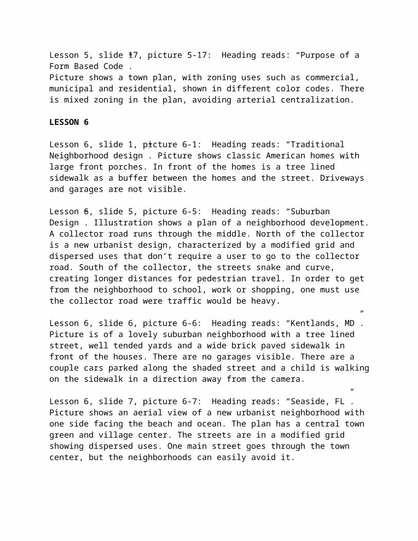
Lesson 6, slide 7, picture 6-7: Heading reads: “Seaside, FL”. Picture shows an aerial view of a new urbanist neighborhood with one side facing the beach and ocean. The plan has a central town green and village center. The streets are in a modified grid showing dispersed uses. One main street goes through the town center, but the neighborhoods can easily avoid it.
Lesson 6, slide 8, picture 6-8: Heading reads: “Celebration, FL”. There are three Pictures: The first picture is of a sidewalk that runs along the front of homes with front porches and white picket fences. There are trees planted in a grass strip between the sidewalk and curb. The other two pictures are two views of the same street. One is from the pedestrian perspective and shows a sidewalk in front of homes and a tree lined grass strip between the street and sidewalk. The third photo is from the perspective of the motorist and shows a view from the car while driving down the street.
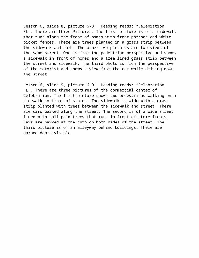
Lesson 6, slide 9, picture 6-9: Heading reads: “Celebration, FL”. There are three pictures of the commercial center of Celebration: The first picture shows two pedestrians walking on a sidewalk in front of stores. The sidewalk is wide with a grass strip planted with trees between the sidewalk and street. There are cars parked along the street. The second is of a wide street lined with tall palm trees that runs in front of store fronts. Cars are parked at the curb on both sides of the street. The third picture is of an alleyway behind buildings. There are garage doors visible.
LESSON 7
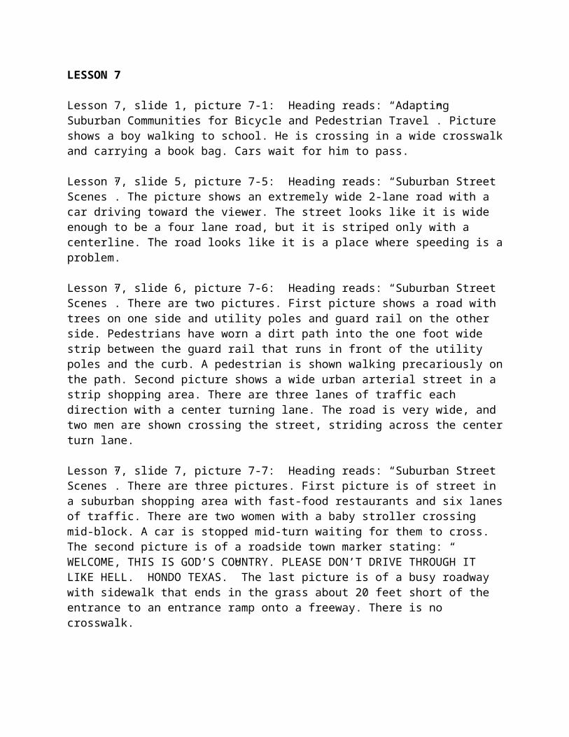
Lesson 7, slide 1, picture 7-1: Heading reads: “Adapting Suburban Communities for Bicycle and Pedestrian Travel”. Picture shows a boy walking to school. He is crossing in a wide crosswalk and carrying a book bag. Cars wait for him to pass.
Lesson 7, slide 5, picture 7-5: Heading reads: “Suburban Street Scenes”. The picture shows an extremely wide 2-lane road with a car driving toward the viewer. The street looks like it is wide enough to be a four lane road, but it is striped only with a centerline. The road looks like it is a place where speeding is a problem.
Lesson 7, slide 6, picture 7-6: Heading reads: “Suburban Street Scenes”. There are two pictures. First picture shows a road with trees on one side and utility poles and guard rail on the other side. Pedestrians have worn a dirt path into the one foot wide strip between the guard rail that runs in front of the utility poles and the curb. A pedestrian is shown walking precariously on the path. Second picture shows a wide urban arterial street in a strip shopping area. There are three lanes of traffic each direction with a center turning lane. The road is very wide, and two men are shown crossing the street, striding across the center turn lane.
Lesson 7, slide 7, picture 7-7: Heading reads: “Suburban Street Scenes”. There are three pictures. First picture is of street in a suburban shopping area with fast-food restaurants and six lanes of traffic. There are two women with a baby stroller crossing mid-block. A car is stopped mid-turn waiting for them to cross. The second picture is of a roadside town marker stating: “ WELCOME, THIS IS GOD’S COUNTRY. PLEASE DON’T DRIVE THROUGH IT LIKE HELL. HONDO TEXAS.” The last picture is of a busy roadway with sidewalk that ends in the grass about 20 feet short of the entrance to an entrance ramp onto a freeway. There is no crosswalk.
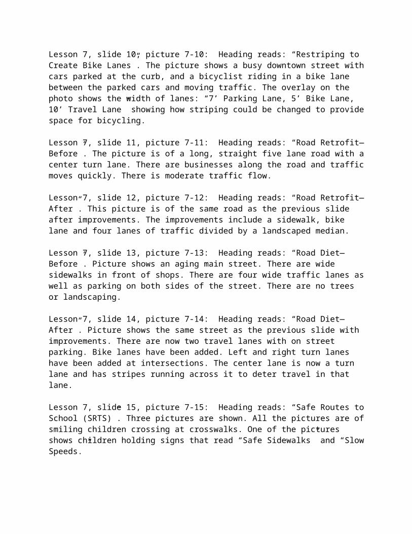
Lesson 7, slide 10, picture 7-10: Heading reads: “Restriping to Create Bike Lanes”. The picture shows a busy downtown street with cars parked at the curb, and a bicyclist riding in a bike lane between the parked cars and moving traffic. The overlay on the photo shows the width of lanes: “7’ Parking Lane, 5’ Bike Lane, 10’ Travel Lane” showing how striping could be changed to provide space for bicycling.
Lesson 7, slide 11, picture 7-11: Heading reads: “Road Retrofit—Before”. The picture is of a long, straight five lane road with a center turn lane. There are businesses along the road and traffic moves quickly. There is moderate traffic flow.
Lesson 7, slide 12, picture 7-12: Heading reads: “Road Retrofit—After”. This picture is of the same road as the previous slide after improvements. The improvements include a sidewalk, bike lane and four lanes of traffic divided by a landscaped median.
Lesson 7, slide 13, picture 7-13: Heading reads: “Road Diet—Before”. Picture shows an aging main street. There are wide sidewalks in front of shops. There are four wide traffic lanes as well as parking on both sides of the street. There are no trees or landscaping.
Lesson 7, slide 14, picture 7-14: Heading reads: “Road Diet—After”. Picture shows the same street as the previous slide with improvements. There are now two travel lanes with on street parking. Bike lanes have been added. Left and right turn lanes have been added at intersections. The center lane is now a turn lane and has stripes running across it to deter travel in that lane.
Lesson 7, slide 15, picture 7-15: Heading reads: “Safe Routes to School (SRTS)”. Three pictures are shown. All the pictures are of smiling children crossing at crosswalks. One of the pictures shows children holding signs that read “Safe Sidewalks” and “Slow Speeds.”
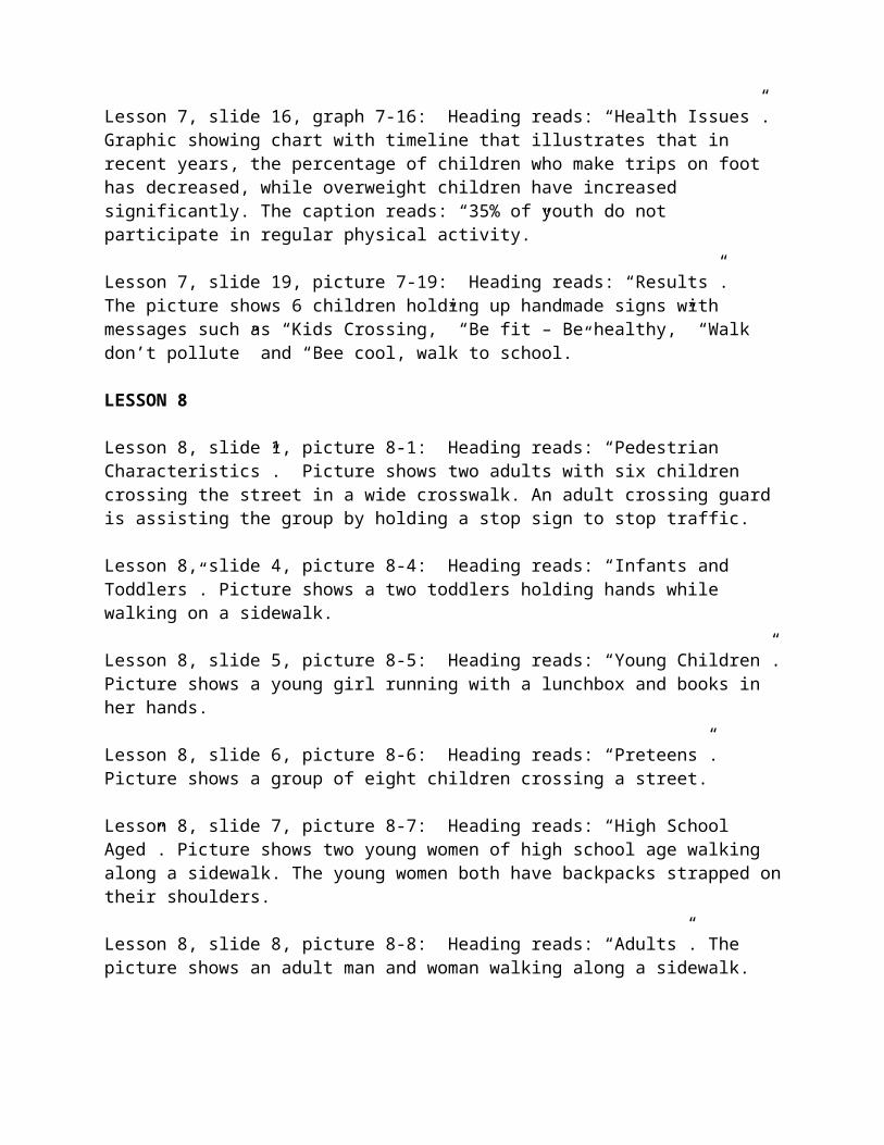
Lesson 7, slide 16, graph 7-16: Heading reads: “Health Issues”. Graphic showing chart with timeline that illustrates that in recent years, the percentage of children who make trips on foot has decreased, while overweight children have increased significantly. The caption reads: “35% of youth do not participate in regular physical activity.”
Lesson 7, slide 19, picture 7-19: Heading reads: “Results”. The picture shows 6 children holding up handmade signs with messages such as “Kids Crossing,” “Be fit – Be healthy,” “Walk don’t pollute” and “Bee cool, walk to school.”
LESSON 8
Lesson 8, slide 1, picture 8-1: Heading reads: “Pedestrian Characteristics”. Picture shows two adults with six children crossing the street in a wide crosswalk. An adult crossing guard is assisting the group by holding a stop sign to stop traffic.
Lesson 8, slide 4, picture 8-4: Heading reads: “Infants and Toddlers”. Picture shows a two toddlers holding hands while walking on a sidewalk.
Lesson 8, slide 5, picture 8-5: Heading reads: “Young Children”. Picture shows a young girl running with a lunchbox and books in her hands.
Lesson 8, slide 6, picture 8-6: Heading reads: “Preteens”. Picture shows a group of eight children crossing a street.
Lesson 8, slide 7, picture 8-7: Heading reads: “High School Aged”. Picture shows two young women of high school age walking along a sidewalk. The young women both have backpacks strapped on their shoulders.
Lesson 8, slide 8, picture 8-8: Heading reads: “Adults”. The picture shows an adult man and woman walking along a sidewalk.
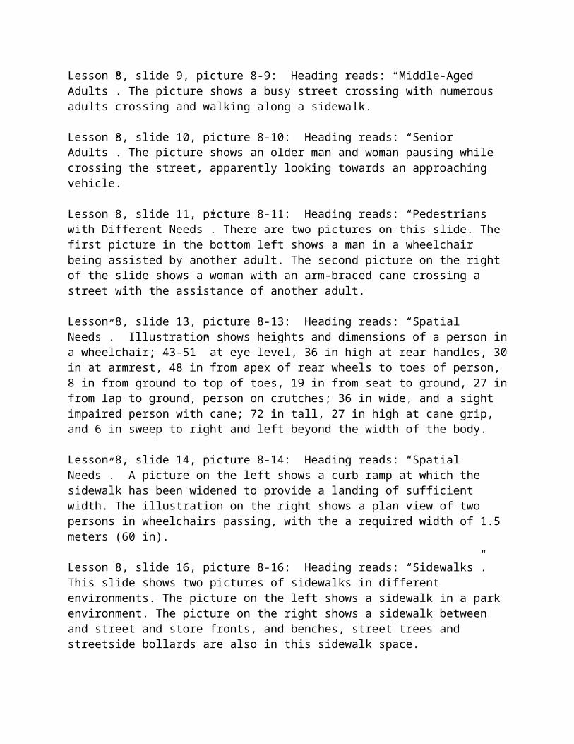
Lesson 8, slide 9, picture 8-9: Heading reads: “Middle-Aged Adults”. The picture shows a busy street crossing with numerous adults crossing and walking along a sidewalk.
Lesson 8, slide 10, picture 8-10: Heading reads: “Senior Adults”. The picture shows an older man and woman pausing while crossing the street, apparently looking towards an approaching vehicle.
Lesson 8, slide 11, picture 8-11: Heading reads: “Pedestrians with Different Needs”. There are two pictures on this slide. The first picture in the bottom left shows a man in a wheelchair being assisted by another adult. The second picture on the right of the slide shows a woman with an arm-braced cane crossing a street with the assistance of another adult.
Lesson 8, slide 13, picture 8-13: Heading reads: “Spatial Needs”. Illustration shows heights and dimensions of a person in a wheelchair; 43-51” at eye level, 36 in high at rear handles, 30 in at armrest, 48 in from apex of rear wheels to toes of person, 8 in from ground to top of toes, 19 in from seat to ground, 27 in from lap to ground, person on crutches; 36 in wide, and a sight impaired person with cane; 72 in tall, 27 in high at cane grip, and 6 in sweep to right and left beyond the width of the body.
Lesson 8, slide 14, picture 8-14: Heading reads: “Spatial Needs”. A picture on the left shows a curb ramp at which the sidewalk has been widened to provide a landing of sufficient width. The illustration on the right shows a plan view of two persons in wheelchairs passing, with the a required width of 1.5 meters (60 in).
Lesson 8, slide 16, picture 8-16: Heading reads: “Sidewalks”. This slide shows two pictures of sidewalks in different environments. The picture on the left shows a sidewalk in a park environment. The picture on the right shows a sidewalk between and street and store fronts, and benches, street trees and streetside bollards are also in this sidewalk space.
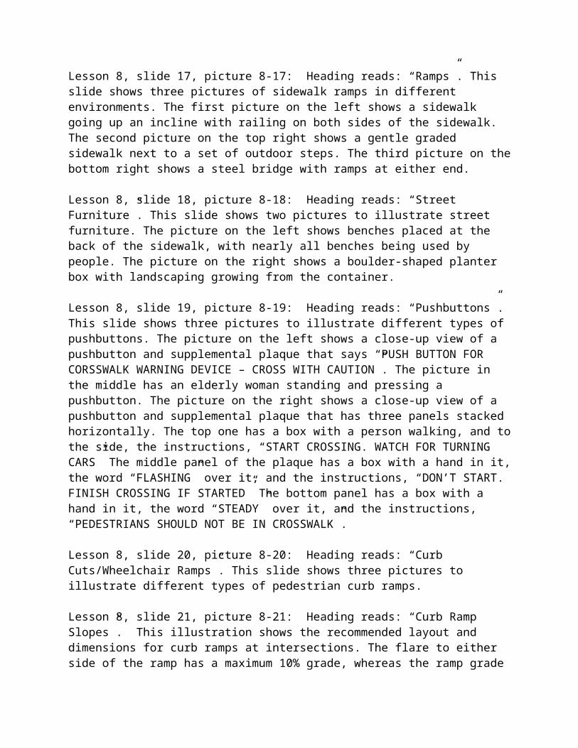
Lesson 8, slide 17, picture 8-17: Heading reads: “Ramps”. This slide shows three pictures of sidewalk ramps in different environments. The first picture on the left shows a sidewalk going up an incline with railing on both sides of the sidewalk. The second picture on the top right shows a gentle graded sidewalk next to a set of outdoor steps. The third picture on the bottom right shows a steel bridge with ramps at either end.
Lesson 8, slide 18, picture 8-18: Heading reads: “Street Furniture”. This slide shows two pictures to illustrate street furniture. The picture on the left shows benches placed at the back of the sidewalk, with nearly all benches being used by people. The picture on the right shows a boulder-shaped planter box with landscaping growing from the container.
Lesson 8, slide 19, picture 8-19: Heading reads: “Pushbuttons”. This slide shows three pictures to illustrate different types of pushbuttons. The picture on the left shows a close-up view of a pushbutton and supplemental plaque that says “PUSH BUTTON FOR CORSSWALK WARNING DEVICE – CROSS WITH CAUTION”. The picture in the middle has an elderly woman standing and pressing a pushbutton. The picture on the right shows a close-up view of a pushbutton and supplemental plaque that has three panels stacked horizontally. The top one has a box with a person walking, and to the side, the instructions, “START CROSSING. WATCH FOR TURNING CARS” The middle panel of the plaque has a box with a hand in it, the word “FLASHING” over it, and the instructions, “DON’T START. FINISH CROSSING IF STARTED” The bottom panel has a box with a hand in it, the word “STEADY” over it, and the instructions, “PEDESTRIANS SHOULD NOT BE IN CROSSWALK”.
Lesson 8, slide 20, picture 8-20: Heading reads: “Curb Cuts/Wheelchair Ramps”. This slide shows three pictures to illustrate different types of pedestrian curb ramps.
Lesson 8, slide 21, picture 8-21: Heading reads: “Curb Ramp Slopes”. This illustration shows the recommended layout and dimensions for curb ramps at intersections. The flare to either side of the ramp has a maximum 10% grade, whereas the ramp grade maximum is 8.33%. A level landing is provided on the sidewalk at the top of the curb ramp, having dimensions of 1.5 meters (5 ft) square. A detectable warning is at the base of the ramp abutting the curb line, with dimensions of 1.2 meters (4 ft) wide (same width as curb ramp) by 600 mm (24 in) deep.
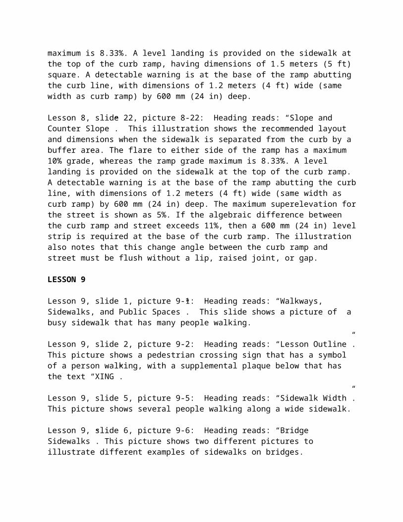
Lesson 8, slide 22, picture 8-22: Heading reads: “Slope and Counter Slope”. This illustration shows the recommended layout and dimensions when the sidewalk is separated from the curb by a buffer area. The flare to either side of the ramp has a maximum 10% grade, whereas the ramp grade maximum is 8.33%. A level landing is provided on the sidewalk at the top of the curb ramp. A detectable warning is at the base of the ramp abutting the curb line, with dimensions of 1.2 meters (4 ft) wide (same width as curb ramp) by 600 mm (24 in) deep. The maximum superelevation for the street is shown as 5%. If the algebraic difference between the curb ramp and street exceeds 11%, then a 600 mm (24 in) level strip is required at the base of the curb ramp. The illustration also notes that this change angle between the curb ramp and street must be flush without a lip, raised joint, or gap.
LESSON 9
Lesson 9, slide 1, picture 9-1: Heading reads: “Walkways, Sidewalks, and Public Spaces”. This slide shows a picture of a busy sidewalk that has many people walking.
Lesson 9, slide 2, picture 9-2: Heading reads: “Lesson Outline”. This picture shows a pedestrian crossing sign that has a symbol of a person walking, with a supplemental plaque below that has the text “XING”.
Lesson 9, slide 5, picture 9-5: Heading reads: “Sidewalk Width”. This picture shows several people walking along a wide sidewalk.
Lesson 9, slide 6, picture 9-6: Heading reads: “Bridge Sidewalks”. This picture shows two different pictures to illustrate different examples of sidewalks on bridges.
Lesson 9, slide 7, picture 9-7: Heading reads: “Rural Sidewalks”. This picture shows a rural roadway that has a paved shoulder. A bicyclists is riding on the paved shoulder, with a few vehicles approaching in the far distance.
Lesson 9, slide 8, picture 9-8: Heading reads: “Border Areas and Buffers”. This slide has two pictures to illustrate examples of landscaping used to separate the street from the sidewalk. In the picture on the left, a solid hedge with intermittent trees is used to provide a continuous buffer between the sidewalk and the street. In the picture on the right, grass with periodic palm trees is used in this buffer space.
Lesson 9, slide 9, picture 9-9: Heading reads: “Grade”. This picture shows a street on an extremely steep hill. Steps are used along the street in place of the sidewalk.
Lesson 9, slide 10, picture 9-10: Heading reads: “Pavement Surfaces”. This picture shows a sidewalk that has been constructed with an artistic pattern using concrete paver stones.
Lesson 9, slide 11, picture 9-11: Heading reads: “Stairs”. This picture shows the landing at the top of a set of outdoor stairs.
Lesson 9, slide 12, picture 9-12: Heading reads: “Corners”. This slide shows two pictures to illustrate examples of curb return radius at street corners.
Lesson 9, slide 13, picture 9-13: Heading reads: “Shy Distances”. This picture shows a sitting area along a sidewalk which contains trees, benches, and trash receptacles.
Lesson 9, slide 14, picture 9-14: Heading reads: “Continuity”. This picture shows a grid street network that has a relatively high level of continuity.
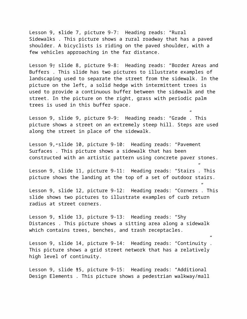
Lesson 9, slide 15, picture 9-15: Heading reads: “Additional Design Elements”. This picture shows a pedestrian walkway/mall area between storefronts. The space looks inviting, with large trees providing shade and abundant landscaping.
Lesson 9, slide 16, picture 9-16: Heading reads: “Public Spaces”. This picture shows a pedestrian plaza with dining tables covered by umbrellas. Several people are dining at the tables, and other people are walking through the plaza.
LESSON 10
Lesson 10, slide 1, picture 10-1: Heading reads: “Pedestrian Facility Signing and Pavement Markings”. This picture shows a pedestrian crosswalk that has wide painted bars parallel to the direction of vehicle travel. Several people are crossing the street, and the text “LOOK RIGHT” is painted on the street next to the curb.
Lesson 10, slide 3, picture 10-3: Heading reads: “Regulatory Signs”. This picture shows several examples of regulatory signs from the Manual of Uniform Traffic Control Devices.
Lesson 10, slide 4, picture 10-4: Heading reads: “Warning Signs”. This picture shows several examples of warning signs from the Manual of Uniform Traffic Control Devices.
Lesson 10, slide 5, picture 10-5: Heading reads: “Directional Signs”. This picture shows several examples of directional signs from the Manual of Uniform Traffic Control Devices.
Lesson 10, slide 6, picture 10-6: Heading reads: “Pavement Word and Symbol Markings”. This slide shows two pictures that illustrate examples of pavement word and symbol markings. The picture on the left shows the following text painted on the pavement: “PED XING”. The picture
on the right shows a STOP bar painted at a intersection, with several vehicles stopped behind the white painted lines.
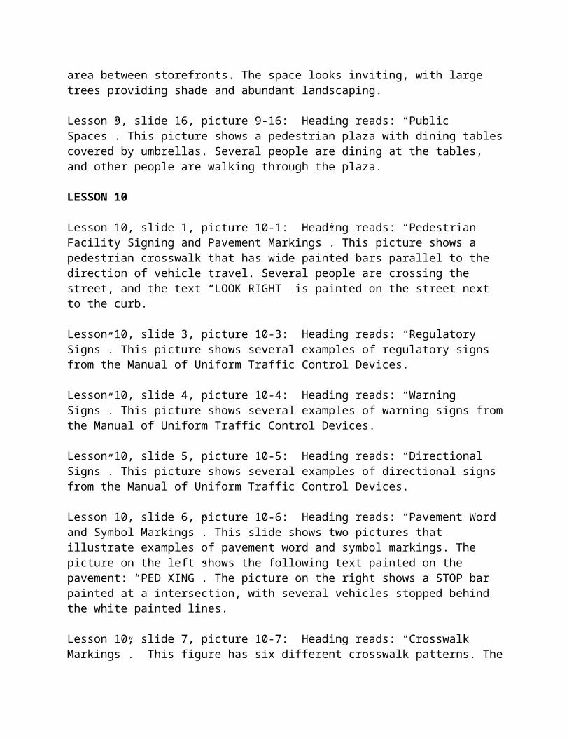
Lesson 10, slide 7, picture 10-7: Heading reads: “Crosswalk Markings”. This figure has six different crosswalk patterns. The first, Solid, is a filled-in rectangle; the second, Standard, is two parallel lines running vertically; the third, Continental, has seven thick lines running horizontally; the fourth, Dashed, has two dashed lines parallel to each other running vertically; the fifth, Zebra, has two parallel lines running vertically with diagonal lines inside the outer two; and the sixth, Ladder, has two parallel lines running vertically and six thick lines running horizontally inside the other two (like a combination of the Standard and the Continental together).
Lesson 10, slide 9, picture 10-9: Heading reads: “In-Roadway Warning Lights”. This photo shows a view from the sky of a zebra crossing (two parallel lines running perpendicular to the roadway with diagonal lines inside the outer two) with in-roadway warning lights located on the outside of the crosswalk.
Lesson 10, slide 10, picture 10-0: Heading reads: “Pedestrian Countdown Signals”. This photo is a close up of a signal pole with a pedestrian countdown signal that has an outline of a hand and the number “1” to the right of the hand, indicating that there is one second left to cross the intersection safely.
Lesson 10, slide 11, picture 10-1: Heading reads: “Animated Eyes Display”. The animated eyes display has two lighted blue eyes at the top of the box, a hand (not yet flashing) on the left side, and LED lights outlining a pedestrian on the right.
Lesson 10, slide 12, picture 10-2: Heading reads: “Detection Devices”. This slide includes four pictures that illustrate examples of different types of pedestrian detection devices. In each picture, a small metal box-like device is attached to a pole and is pointed at the general area where pedestrians are likely to be walking.
Lesson 10, slide 13, picture 10-3: Heading reads: “Illuminated Pushbuttons”. This slide shows two pictures to illustrate an example of an illuminated pushbutton. In the picture on the left, a metal pushbutton is shown below a crossing explanation plaque. The picture on the right shows an enlarged view of the pushbutton, and a small circle is visible in the middle of the metal pushbutton. This small circle is lighted when the pushbutton has been pressed.
LESSON 11
Lesson 11, slide 1, picture 11-1: Heading reads: “Pedestrian Design at Intersections”. Use of colored crosswalks and median refuges makes this intersection more pedestrian-friendly. This is an aerial photograph of a wide intersection of a seven-lane major road with a four-lane minor road. Crosswalks are defined at each approach using colored paver stones, and refuge islands at the center of the major road make crossing the wide roadway less of a challenge.
Lesson 11, slide 4, picture 11-4: Heading reads: “Reduced Visibility”. Reduced visibility of pedestrians behind parked cars can create conflict. In this photo, an older man and woman stand at the front of a car parked on the side of the road and look to their left to scan for any cars coming from behind the row of parked cars.
Lesson 11, slide 5, picture 11-5: Heading reads: “Alternative Design”. This figure has a “before” sketch of a 17.4-meter (58 ft) roadway with (from left to right) a lane for vertically-parked cars, two lanes of traffic, a bike lane, and a lane of parallel parking. The “after” figure has the same total lane width, but it also has curb extensions at the intersection on both sides of the roadway. The curb extensions come out to the end of the parking lanes but do not obstruct the two through lanes or the bike lane. The new distance the pedestrian would have to cross is 9.6 m (32 ft).
Lesson 11, slide 7, picture 11-7: Heading reads: “Common Crosswalk Types”. This figure has six different crosswalk patterns. The first, Solid, is a filled-in rectangle; the second, Standard, is two parallel lines running vertically; the third, Continental, has seven thick lines running horizontally; the fourth, Dashed, has two dashed lines parallel to each other running vertically; the fifth, Zebra, has two parallel lines running vertically with diagonal lines inside the outer two; and the sixth, Ladder, has two parallel lines running vertically and six thick lines running horizontally inside the other two (like a combination of the Standard and the Continental together).
Lesson 11, slide 9, picture 11-9: Heading reads: “Curb Ramp Slopes”. This illustration shows the recommended layout and dimensions for curb ramps at intersections. The flare to either side of the ramp has a maximum 10% grade, whereas the ramp grade maximum is 8.33%. A level landing is provided on the sidewalk at the top of the curb ramp, having dimensions of 1.5 meters (5 ft) square. A detectable warning is at the base of the ramp abutting the curb line, with dimensions of 1.2 meters (4 ft) wide (same width as curb ramp) by 600 mm (24 in) deep.
Lesson 11, slide 10, picture 11-10: Heading reads: “Slope and Counter Slope”. This illustration shows the recommended layout and dimensions when the sidewalk is separated from the curb by a buffer area. The flare to either side of the ramp has a maximum 10% grade, whereas the ramp grade maximum is 8.33%. A level landing is provided on the sidewalk at the top of the curb ramp. A detectable warning is at the base of the ramp abutting the curb line, with dimensions of 1.2 meters (4 ft) wide (same width as curb ramp) by 600 mm (24 in) deep. The maximum superelevation for the street is shown as 5%. If the algebraic difference between the curb ramp and street exceeds 11%, then a 600 mm (24 in) level strip is required at the base of the curb ramp. The illustration also notes that this change angle between the curb ramp and street must be flush without a lip, raised joint, or gap.
Lesson 11, slide 12, picture 11-12: Heading reads: “In-Roadway Warning Lights”. The first example shows a person walking across a midblock crosswalk marked with thick bars running parallel to the road (a Continental style crosswalk). On the outside of the crosswalk, in-roadway warning lights face oncoming traffic in either direction and illuminate the boundaries of the crosswalk. Second photo shows a view from the sky of a zebra crossing (two parallel lines
running perpendicular to the roadway with diagonal lines inside the outer two) with in-roadway warning lights located on the outside of the crosswalk.
Lesson 11, slide 14, picture 11-14: Heading reads: “Example of Half Signal”. This photo shows the intersection of a major roadway with a minor one and a continental-style crosswalk going across the major road. Above the major road is a span wire with two signal heads in each direction and a pedestrian sign to warn motorists of pedestrian presence.
Lesson 11, slide 17, picture 11-17: Heading reads: “Pushbuttons”. This slide shows three pictures to illustrate different types of pushbuttons. The picture on the left shows a close-up view of a pushbutton and supplemental plaque that says “PUSH BUTTON FOR CORSSWALK WARNING DEVICE – CROSS WITH CAUTION”. The picture in the middle has an elderly woman standing and pressing a pushbutton. The picture on the right shows a close-up view of a pushbutton and supplemental plaque that has three panels stacked horizontally. The top one has a box with a person walking, and to the side, the instructions, “START CROSSING. WATCH FOR TURNING CARS” The middle panel of the plaque has a box with a hand in it, the word “FLASHING” over it, and the instructions, “DON’T START. FINISH CROSSING IF STARTED” The bottom panel has a box with a hand in it, the word “STEADY” over it, and the instructions, “PEDESTRIANS SHOULD NOT BE IN CROSSWALK”.
Lesson 11, slide 20, picture 11-20: Heading reads: “Conflict Points at Intersections”. 1) Roundabouts have eight vehicle/pedestrian conflict points. This diagram shows a modern roundabout design with a four-leg approach and the limited (8) conflict points that vehicles can have with pedestrians. 2) This diagram shows a standard intersection with a four-leg approach and the various (16) conflict points that vehicles can have with pedestrians.
LESSON 12
Lesson 12, slide 1, picture 12-1: Heading reads: “Midblock Crossings”. The picture shows a mid-block pedestrian crossing with continental crosswalk marking and an in-roadway warning sign. A pedestrian crossing sign is also posted at the edge of the street on a pole.
Lesson 12, slide 8, picture 12-8: Heading reads: “Design Considerations for Using Medians”. 1) Midblock crossing curb extensions provide better visibility for motorists and pedestrians. In this figure, two lanes of traffic are moving in each direction, divided by a landscaped median. There is a bike lane and a lane for parallel parking on the far outsides of the street in both directions. At a midblock crossing point, with a continental-style crosswalk pattern and lit by street lights, there is a curb extension which juts out to the end of the parking lane, not restricting the bike lane. This allows for pedestrians to have a shorter crossing distance across the roadway. 2) This photo shows a two-lane road with a curb extension and a crosswalk with no signal or intersection nearby.
Lesson 12, slide 9, picture 12-9: Heading reads: “Pedestrian Crossing Examples”. 1) In this illustration, there is a four-lane roadway divided in the middle by a landscaped median. From the left side of the road, a midblock crossing extends to the median, shifts diagonally downward, and continues straight across the other half of the roadway to the curb on the right side of the figure,
forming a Z shape. This configuration causes pedestrians in the median to turn their bodies toward the oncoming traffic in whichever direction they are walking, helping to make them more aware of the oncoming vehicle traffic. 2) An underpass continues this shared use bicycle path beneath a four-lane highway with high traffic volume. In this photo, a child rides a bike through a wide underpass that leads to a trail. The road over the underpass is a four-lane highway with heavy traffic.
LESSON 13
Lesson 13, slide 1, picture 13-1: Heading reads: “Selecting Bicycle Facility Types and Evaluating Roadways”. 1) This photograph shows a bicyclist riding in the right third of a vehicle lane, and a vehicle has crossed the roadway centerline in order to pass the bicyclist. 2) Bicyclists in a wide curb lane. This photograph shows two bicyclists riding single file in a wide curb lane. Vehicles are passing the bicyclists in the same lane but are not crossing the road centerline. 3) This photograph shows a bicyclist riding in a bike lane, which is separated from the vehicle travel lane by a solid white tranverse pavement marking. A bike symbol pavement marking is also visible in the bike lane. 4) This photograph shows a shared use path that has a pedestrian area separated from a bicyclist area by a solid white line. The bicyclist area on the path is divided into two opposing directions by a white dashed line.
Lesson 13, slide 3, picture 13-3: Heading reads: “Bicycle Facility Types”. 1) This photograph shows a bicyclist riding in the right third of a vehicle lane, and a vehicle has crossed the roadway centerline in order to pass the bicyclist. 2) This photograph shows two bicyclists riding single file in a wide curb lane. Vehicles are passing the bicyclists in the same lane but are not crossing the road centerline.
Lesson 13, slide 4, picture 13-4: Heading reads: “Bicycle Facility Types”. 1) This photograph shows a bicyclist riding in a bike lane, which is separated from the vehicle travel lane by a solid white tranverse pavement marking. A bike symbol pavement marking is also visible in the bike lane. 2) This photograph shows a shared use path that has a pedestrian area separated from a bicyclist area by a solid white line. The bicyclist area on the path is divided into two opposing directions by a white dashed line.
Lesson 13, slide 6, picture 13-6: Heading reads: “Comparison of Approaches”. This bar chart shows the trend that bike lanes or shoulders are used more often for high speed roadways (30 mi/h and above) and at lower traffic volume thresholds. The chart also indicates that for roads with lower speeds (25 mi/h and less), normal or wide lanes are used more often than bike lanes.
Lesson 13, slide 7, picture 13-7: Heading reads: “AASHTO Guidance on Facilities”. This slide contains three pictures that illustrate different categories of bicyclists. The picture on the left shows an advanced bicyclist, or Type A bicyclist. The picture in the middle shows a Type B, or basic, bicyclist. The picture on the right shows several Type C (children) bicyclists.
LESSON 14
Lesson 14, slide 1, picture 14-1: Heading reads: “Shared Roadways”. This photograph shows two bicyclists riding single file in a wide curb lane. Vehicles are passing the bicyclists in the same lane but are not crossing the road centerline.
Lesson 14, slide 3, picture 14-3: Heading reads: “Shared Roadways”. Shared roadways include most existing roads and streets. This illustration shows an elevation view of a shared roadway with no pavement markings. In the sketch, two bicyclists in opposing directions are sharing the roadway with a motor vehicle.
Lesson 14, slide 4, picture 14-4: Heading reads: “Wide Curb Lanes”. This illustration shows an elevation view of a wide curb lane next to an inside travel lane. The dimension of the inside travel lane is 3.6 m (12 ft), whereas the wide curb lane is 4.2 m (14 ft) of usable lane width. In the sketch, no pavement marking separates a bicyclist from a motor vehicle in the wide curb lane.
Lesson 14, slide 5, picture 14-5: Heading reads: “Shared Lane Pavement Markings”. This illustration shows several pavement markings for shared roadways. The first is a “bike and separate arrow” marking and shows a bicyclist symbol below with a thin arrow line above the bike symbol. The second marking is a “bike in house” marking, which shows a bicyclist symbol within the outline of a very wide arrow (which resembles the outline of a house). The third marking is a “modified bike in house” marking which shows a bicyclist symbol within the dashed outline of a very wide arrow (which resembles the outline of a house). The fourth marking shows a bicycle symbol below with double chevrons above, pointing in the direction of travel.
Lesson 14, slide 6, picture 14-6: Heading reads: “Shoulders and Shoulder Bikeways”. This illustration shows an elevation view of dimensions for paved shoulder bikeways. In the sketch, the following road elements have these dimensions: shoulder of 1.2 m (4 ft) minimum, 2 opposing vehicle travel lanes of 3.6 m (12 ft) each, and another shoulder in the opposite direction of 1.2 m (4 ft) minimum. An explanatory note indicates that a minimum shoulder width of 1.5 m (5 ft) is required from face of guardrail, curb, or other roadside barrier.
Lesson 14, slide 7, picture 14-7: Heading reads: “Designated Bike Routes”. This slide contains pictures of examples of bike route signs. The top picture shows a bicycle symbol with the text “BIKE ROUTE” below. The bottom picture shows a bicycle symbol with a large number “4” below.
Lesson 14, slide 8, picture 14-8: Heading reads: “Bicycle Boulevards”. This picture shows a bicyclist and pedestrian traveling along a bicycle boulevard. At the intersection, motor vehicle traffic is not permitted to travel straight across the intersection. Instead, motor vehicle traffic is forced to turn right.
Lesson 14, slide 9, picture 14-9: Heading reads: “Rumble Strips”. This picture shows a bike lane which has rumble strips along the left edge. Accompanying text says “AVOID THIS! (rumble strips in bike lane)”.
Lesson 14, slide 10, picture 14-10: Heading reads: “Drainage Grates”. This illustration shows three different styles of bicycle-safe grates. The first style has a honeycomb pattern. The second style has a grate pattern in which the slots are perpendicular to the direction of bike travel. The third style has a grate pattern in which the slots are parallel to the direction of bike travel, but there are cross spacers that limit the maximum slot length to 150 mm (6 in).
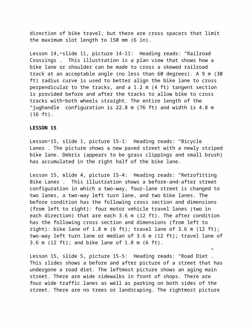
Lesson 14, slide 11, picture 14-11: Heading reads: “Railroad Crossings”. This illustration is a plan view that shows how a bike lane or shoulder can be made to cross a skewed railroad track at an acceptable angle (no less than 60 degrees). A 9 m (30 ft) radius curve is used to better align the bike lane to cross perpendicular to the tracks, and a 1.2 m (4 ft) tangent section is provided before and after the tracks to allow bike to cross tracks with both wheels straight. The entire length of the “jughandle” configuration is 22.8 m (76 ft) and width is 4.8 m (16 ft).
LESSON 15
Lesson 15, slide 1, picture 15-1: Heading reads: “Bicycle Lanes”. The picture shows a new paved street with a newly striped bike lane. Debris (appears to be grass clippings and small brush) has accumulated in the right half of the bike lane.
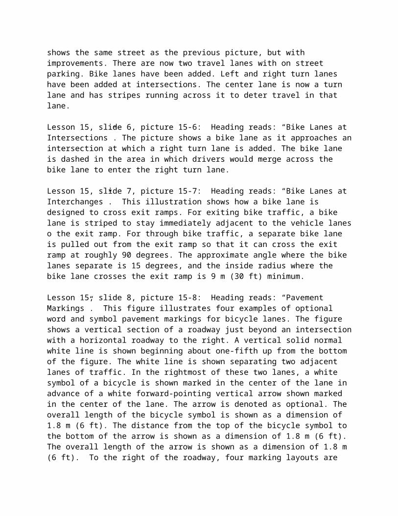
Lesson 15, slide 4, picture 15-4: Heading reads: “Retrofitting Bike Lanes”. This illustration shows a before-and-after street configuration in which a two-way, four-lane street is changed to two lanes, a two-way left turn lane, and two bike lanes. The before condition has the following cross section and dimensions (from left to right): four motor vehicle travel lanes (two in each direction) that are each 3.6 m (12 ft). The after condition has the following cross section and dimensions (from left to right): bike lane of 1.8 m (6 ft); travel lane of 3.6 m (12 ft); two-way left turn lane or median of 3.6 m (12 ft); travel lane of 3.6 m (12 ft); and bike lane of 1.8 m (6 ft).
Lesson 15, slide 5, picture 15-5: Heading reads: “Road Diet”. This slides shows a before and after picture of a street that has undergone a road diet. The leftmost picture shows an aging main street. There are wide sidewalks in front of shops. There are four wide traffic lanes as well as parking on both sides of the street. There are no trees or landscaping. The rightmost picture shows the same street as the previous picture, but with improvements. There are now two travel lanes with on street parking. Bike lanes have been added. Left and right turn lanes have been added at intersections. The center lane is now a turn lane and has stripes running across it to deter travel in that lane.
Lesson 15, slide 6, picture 15-6: Heading reads: “Bike Lanes at Intersections”. The picture shows a bike lane as it approaches an intersection at which a right turn lane is added. The bike lane is dashed in the area in which drivers would merge across the bike lane to enter the right turn lane.
Lesson 15, slide 7, picture 15-7: Heading reads: “Bike Lanes at Interchanges”. This illustration shows how a bike lane is designed to cross exit ramps. For exiting bike traffic, a bike lane is striped to stay immediately adjacent to the vehicle lanes o the exit ramp. For through bike traffic, a separate bike lane is pulled out from the exit ramp so that it can cross the exit ramp at roughly
90 degrees. The approximate angle where the bike lanes separate is 15 degrees, and the inside radius where the bike lane crosses the exit ramp is 9 m (30 ft) minimum.
Lesson 15, slide 8, picture 15-8: Heading reads: “Pavement Markings”. This figure illustrates four examples of optional word and symbol pavement markings for bicycle lanes. The figure shows a vertical section of a roadway just beyond an intersection with a horizontal roadway to the right. A vertical solid normal white line is shown beginning about one-fifth up from the bottom of the figure. The white line is shown separating two adjacent lanes of traffic. In the rightmost of these two lanes, a white symbol of a bicycle is shown marked in the center of the lane in advance of a white forward-pointing vertical arrow shown marked in the center of the lane. The arrow is denoted as optional. The overall length of the bicycle symbol is shown as a dimension of 1.8 m (6 ft). The distance from the top of the bicycle symbol to the bottom of the arrow is shown as a dimension of 1.8 m (6 ft). The overall length of the arrow is shown as a dimension of 1.8 m (6 ft). To the right of the roadway, four marking layouts are shown. Each marking is superimposed on a vertical rectangular shaped set of squares called a “grid”; each square is denoted as being a dimension of 100 x 100 mm (4 x 4 in). The symbols shown are a forward-pointing vertical directional arrow, a bicycle, and a bicycle detector symbol, showing a person wearing a helmet riding a bicycle. To the right of the symbols, word legends are shown on a “grid” and denoted as optional. On this grid, the word “BIKE” is shown in advance of the word “LANE.”
Lesson 15, slide 9, picture 15-9: Heading reads: “Signing”. This figure illustrates 23 regulatory signs for bicycle facilities.
R1-1 is shown as an octagonal sign with a white border and the legend "STOP" in white on a red background.
R1-2 is shown as a downward-pointing equilateral triangle with a wide red border and the legend "YIELD" in red on a white background.
R3-17 is shown as a horizontal rectangular black sign with a white border. A white symbol of a bicycle is shown on the top two-thirds of the sign. A white panel is shown on the bottom third of the sign with the words "BIKE LANE" in black.
R3-17a is shown as a horizontal rectangular white sign with a black border and the word "AHEAD" in black.
R3-17b is shown as a horizontal rectangular white sign with a black border and the word "ENDS" in black.
R4-1 is shown as a vertical rectangular white sign with a black border and the words "DO NOT PASS" in black on three lines.
R4-2 is shown as a vertical rectangular white sign with a black border and the words "PASS WITH CARE" in black on three lines.
R4-3 is shown as a vertical rectangular white sign with a black border and the words "SLOWER TRAFFIC KEEP RIGHT" in black on four lines.
R4-4 is shown as a horizontal rectangular white sign with a black border and legend. It shows the words "BEGIN RIGHT TURN LANE" on two lines above a diagonal arrow pointing down and to the left above the words "YIELD TO BIKES."
R4-7 is shown as a vertical rectangular white sign with a black border and legend. At the top left corner of the sign, a depiction of the plan view of the nose of a traffic island is shown. An upward-pointing arrow is shown on the sign, curving to depict movement to the right of the nose of the island.
R5-1b is shown as a vertical rectangular red sign with a white border and legend. It shows a white symbol of a bicycle above the words "WRONG WAY" on two lines.
R9-3c is shown as a square white sign with a black border and the words "RIDE WITH TRAFFIC" in black on three lines. It is shown directly below the R5-1b sign.
R5-3 is shown as a square white sign with a black border and the words "NO MOTOR VEHICLES" in black on three lines.
R5-6 is shown as a square white sign with a black border. A black symbol of a left-facing bicycle is shown with a red circle and diagonal red slash running from the upper left to the lower right superimposed on it.
R7-9 is shown as a vertical rectangular white sign with a red border and the words "NO PARKING" in a panel in the top fourth of the sign. The word "NO" is shown in large white letters on a red panel in the upper left quadrant of the sign to the left of the word "PARKING" in red. Below this panel, the words "BIKE LANE" in red are shown on two lines.
R7-9a is shown as a vertical rectangular white sign with a red border and legend. It shows a black letter "P" inside a red circle with a red diagonal slash superimposed on it above the words "BIKE LANE" in red on two lines.
R9-3a is shown as a square white sign with a black border and a black symbol of a walking person inside a red circle with a diagonal red slash superimposed on the symbol.
R9-5 is shown as a vertical rectangular white sign with a black border and legend. It shows a symbol of a bicycle above the words "USE PED SIGNAL" on three lines.
R9-6 is shown as a vertical rectangular white sign with a black border and legend. It shows a symbol of a bicycle above the words "YIELD TO PEDS" on three lines.
R9-7 is shown as a vertical rectangular white sign with a black border and legend. It shows the word "KEEP" in large letters on the top line, the words "LEFT" and "RIGHT" on the second line, with a symbol of a bicycle under the word "LEFT" and a symbol of a person
walking under the word "RIGHT." A vertical black line separates the word "LEFT" and bicycle symbol from the word "RIGHT" and person walking symbol.
R10-3 is shown as a vertical rectangular white sign with a black border and the words "PUSH BUTTON FOR GREEN LIGHT" in black on five lines.
R10-22 is shown as a vertical rectangular white sign with a black border and legend. It shows the words "TO REQUEST GREEN" on the top line above the words "WAIT ON" to the left of a symbol of a person on a bicycle superimposed on a vertical black line.
R15-1 is shown as composed of two horizontal rectangular white signs placed one on top of the other to form an "x," denoting a crossbuck. In black letters, the word "RAILROAD" is shown on the piece running from northwest to southeast, and the word "CROSSING" is shown on the piece running from southwest to northeast.
Lesson 15, slide 10, picture 15-10: Heading reads: “Colored Bike Lanes”. This photograph show the use of a blue bike lane in Portland, Oregon. The pavement surface of the bike lane is colored blue where an entrance ramp crosses it. A sign on the entrance ramp indicates that motor vehicles are to yield to bikes in the blue bike lane.
Lesson 15, slide 11, picture 15-11: Heading reads: “Contraflow Bike Lanes”. This photograph shows a contraflow lane that runs counter to the motor vehicle traffic lanes. The contraflow bike lane is separated from the vehicle lanes by a concrete divider, and a special signal is used for the bike lane. A sign next to the bike signal says “ONCOMING TRAFFIC HAS LONGER GREEN”.
Lesson 15, slide 12, picture 15-12: Heading reads: “Practices to Avoid”. This illustration shows that a wrong-way bicyclists is not seen in a driver’s primary field of view. A motorist on the main (vertical) street is preparing to turn left onto a side street and will not be looking for wrong-way bikes traveling parallel and in the same direction. A motorist on the side street who wants to turn right on the main street will also not see this wrong-way bicyclists coming from their right, as he/she is looking to his/her left to merge in traffic.
LESSON 16
Lesson 16, slide 1, picture 16-1: Heading reads: “Bicycle Facility Maintenance”. This photograph shows a woman with a push broom who is cleaning a wide shared use path. Her bicycle is also parked on the path and include a trailer that contains maintenance equipment.
Lesson 16, slide 3, picture 16-3: Heading reads: “Maintenance Objectives”. The photograph shows a new paved street with a newly striped bike lane. Debris (appears to be grass clippings and small brush) has accumulated in the right half of the bike lane.
Lesson 16, slide 6, picture 16-6: Heading reads: “Feedback from Users”. This photograph shows a postcard that is used to identify and report road maintenance issues. The card identifies
the type of problem, the location, a description for why it is a problem, and an area to describe what the reporter thinks should be done about the problem.
LESSON 17
Lesson 17, slide 1, picture 17-1: Heading reads: “Bicycle Parking and Storage”. This photograph shows the frame of a bicycle that has been locked to a railing made of steel pipe. Apparently the wheels, seat, and most of the bike parts and accessories has been stolen while the bike was parked at this location.
Lesson 17, slide 4, picture 17-4: Heading reads: “Types of Bicycle Parking”. This illustration shows three examples of bicycle parking devices. The first type of device is a bike rack, which can be shaped like an inverted “U”, a lollipop, an inverted “U” with a cross brace, or an inverted “W”. The second type of device is a bicycle locker, which is basically a box-shaped enclosure that can be locked from the outside. The third type of device is a bicycle lock-up, which is an open space that has a cage enclosure with bike racks inside for double locking protection.
Lesson 17, slide 7, picture 17-7: Heading reads: “Identify Priority Locations”. This picture shows a bicycle that has been locked to a utility pole.
Lesson 17, slide 8, picture 17-8: Heading reads: “Rack Area Design”. This illustration shows the recommended design dimensions for bicycle rack areas. The plan view sketch shows a bike parking area with two rows of parked bikes, threes bikes in each row. The open space between the two rows of parked bikes is 1.2 m (48 in), and the width (from back to front wheel) of each row is 1.8 m (72 in). The dimension from the actual bike rack to a boundary wall is 0.6 m (24 in) on all sides. A note indicates that all dimensions are recommended minimums.
Lesson 17, slide 9, picture 17-9: Heading reads: “Recommended Rack Designs”. This illustration shows three types of bike racks that are recommended. The first is the post & loop, which resembles a lollipop with the stick attached to the ground. The second is the inverted “U”, which looks as its name implies. The third is the “A” rack, which looks like an inverted “U” rack with a cross brace.
Lesson 17, slide 10, picture 17-10: Heading reads: “Designs NOT Recommended”. This illustration shows three types of bike racks that are not recommended. The first is called a wave, which has an undulating appearance of a wave with the ends of the wave attached to the ground. The second is called a toast, which is a freestanding device that has slots into which front wheel may be placed to support the bike. The third is called a comb, which has several smaller vertical elements through which a front wheel is placed to support the bike. A note indicates that these bike racks are not recommended.
LESSON 18
Lesson 18, slide 1, picture 18-1: Heading reads: “Bicycle and Pedestrian Connections to Transit”. Picture shows two men loading their bicycles onto the front bicycle rack of a city bus.
Lesson 18, slide 2, picture 18-2: Heading reads: “Lesson Outline”. Picture shows a large, attractive bus stop shelter in front of a townhouse/apartment complex.
Lesson 18, slide 4, picture 18-4: Heading reads: “Pedestrian Connections to Transit”. There are two pictures. The first picture shows a woman sitting on the curb of the road waiting for a bus. There is no sidewalk, only a paved shoulder. The second picture shows a bus stop with a sidewalk and a bench between two trees. The bench was placed there by the Lion’s Club. There is a bus stop sign in the grass strip between the sidewalk and the curb.
Lesson 18, slide 5, picture 18-5: Heading reads: “How Bicycles Should Be Integrated With Transit”. Picture shows a bike rack with bikes parked outside a historic train depot.
Lesson 18, slide 6, picture 18-6: Heading reads: “Bicycle-on-Bus Programs”. Picture shows a man loading a bicycle onto a front rack of a city bus.
Lesson 18, slide 8, picture 18-8: Heading reads: “Bicycle-on-Rail Programs”. Picture shows a man with a bicycle riding in a subway car.
LESSON 19
Lesson 19, slide 1, picture 19-1: Heading reads: “Greenways and Shared Use Paths”. Picture shows a seaside multi-use path. The path is divided down the center and there are directional arrows to aid traffic flow. On the right side of the path, two people are walking and a rollerblader is passing them on their left, and on the left (or oncoming lane) is a bicyclist.
Lesson 19, slide 2, picture 19-2: Heading reads: “Lesson Outline”. Picture shows a broad shared use path along a river. A woman is jogging away from the viewer and there is a man rollerblading in the direction of the viewer.
Lesson 19, slide 4, picture 19-4: Heading reads: “Users of Shared Use Paths”. There are three pictures in this slide. First picture shows a man on a motorized scooter. Second picture shows a father and child on a tandem bike pulling a second child in a trail-a-bike. The third picture shows two children on scooters. All the cyclists and scooter riders are wearing helmets.
Lesson 19, slide 7, picture 19-7: Heading reads: “Shared Use Path Design”. There are two pictures and a graphic. The graphic shows a cross section drawing of a bike path: Signage is placed three feet away from the pavement, the path is ten feet wide with a two percent cross slope. A centerline is optional, and on either side is a minimum two foot wide shoulder sloping down from the path. The fist picture shows a wheelchair lift for a pedestrian overpass. The second shows a wide crosswalk with striping.
Lesson 19, slide 8, picture 19-8: Heading reads: “Trail Design Issues”. Five pictures show trail elements. 1.) A picture of a tunnel that conveys a trail beneath a road. 2.) A “Yield to Bikes” sign. 3.) A town limit sign. 4.) A historic marker describing an event in the trails vicinity. 5.) A bronze plate used as a place marker for a significant site.
LESSON 20
Lesson 20, slide 1, picture 20-1: Heading reads: “Traffic Calming”. Picture shows a street that has various traffic calming elements, including curb extensions and chicanes.
Lesson 20, slide 4, picture 20-4: Heading reads: “Need for Traffic Calming”. In this diagram, traffic on a major arterial is congested at an intersection due to faulty signal timing, and cars opt to detour though minor roads adjacent to the major roadway, causing a traffic calming need.
Lesson 20, slide 8, picture 20-8: Heading reads: “Traffic Calming Treatments”. This diagram shows a plan for five blocks across and four blocks down and various traffic calming treatments incorporated at several intersections and corridors: curb extensions, neck downs, traffic circles, diverters, chicanes, and cul-de-sacs.
LESSON 21
Lesson 21, slide 1, picture 21-1: Heading reads: “Bicycle and Pedestrian Accommodation in Work Zones”. This picture shows a sidewalk that has been closed due to construction. Barriers and plastic tape have been placed to discourage pedestrian travel through the construction zone, but no apparent alternate route for pedestrians has been provided.
Lesson 21, slide 4, picture 21-4: Heading reads: “Sidewalk Closure and Pedestrian Detour Example”. This figure illustrates an example of crosswalk closures and pedestrian detours. This figure shows a vertical two-lane roadway with one lane in each direction intersecting two horizontal roadways. Black arrows on the vertical roadway indicate that traffic is one lane in each direction. The opposing lanes on all three roadways are shown separated by a solid double yellow line. Vertical and horizontal sidewalks identified as thick white lines bordered by narrow black lines are shown on both sides of the vertical and horizontal roadways. Crosswalks, shown by parallel solid white lines, are shown extending across all roadways at all the intersections. Solid white lines are shown extending across the approach lanes in advance of the crosswalks at each intersection.
At the bottom of the figure and to the right of the northbound travel lane and south of the lower horizontal roadway, a black inverted "T" is shown denoting a sign. The sign is shown as a diamond-shaped orange sign with a black border and the words "ROAD WORK AHEAD" in black and labeled optional. On the north side of the lower horizontal roadway and to the right and just north of the sidewalk, a horizontal rectangular white sign with a black border is shown with the words "SIDEWALK CLOSED AHEAD" and "CROSS HERE" in black above and below a left-pointing black arrow. Beyond this sign, a horizontal rectangular white sign with a black border and the words "SIDEWALK CLOSED" in black is shown in the middle of the sidewalk. This sign is shown directly in front of an orange and white diagonally striped Type III
barricade, which is shown in front of a vertical rectangle with black and white diagonal stripes, denoting a work space, that is shown extending from the right side of the sidewalk to the right side of the vertical roadway. The work space is shown extending to the south edge of the upper horizontal roadway and then to the right for a short distance, covering the area from the south side of the sidewalk along the south side of the upper roadway to the right edge of the upper horizontal roadway. To the left of the work space along the right edge of the northbound travel lane, a series of orange squares is shown, denoting channelizing devices, that is shown continuing to the south edge of the upper horizontal roadway.
At the intersection of the vertical roadway and the upper horizontal roadway, black circle-and-arrow symbols are shown representing traffic control signals. Four symbols are shown outside of each corner of the intersection, and each is shown pointing to two directions facing the intersection.
On the south side of the upper horizontal roadway, to the left of the intersection with the vertical roadway, a Road Work Ahead sign is shown facing eastbound traffic. On the west side of the vertical roadway, a horizontal rectangular white sign with a black border is shown in the middle of the sidewalk facing eastbound pedestrian traffic with the words "SIDEWALK CLOSED" and "USE OTHER SIDE" in black above and below a double-headed horizontal black arrow. The sign is shown on the short leg of the sidewalk that is shown entering the southbound travel lane and is shown directly in front of two channelizing devices shown blocking the sidewalk and the crosswalk. Another of these signs is shown on the north side of the upper horizontal roadway to the right of the vertical roadway and facing southbound pedestrian traffic. It is shown on the short leg of the sidewalk that is shown entering the westbound travel lane and is shown in front of two channelizing devices shown blocking the sidewalk and crosswalk.
On the south side of the upper horizontal roadway and to the right of the vertical roadway, the work space is shown continuing. Just beyond the crosswalk, a sign assembly is shown facing eastbound vehicular traffic. It is shown composed of a diamond-shaped orange sign with a black border and a black symbol of a left-facing person walking above a horizontal rectangular orange plaque with a black border and the word "AHEAD" in black. The work space is shown continuing and terminating with a Type III barricade at the east end. On the travel lane side of this barricade, a sign assembly is shown facing eastbound vehicular traffic. It is shown composed of a Walking Person symbol sign above a horizontal rectangular orange plaque with a black border and a diagonal black arrow pointing down and to the left. Back to back with this sign assembly, a horizontal rectangular white sign with a black border is shown facing westbound pedestrian traffic. It shows the words "SIDEWALK CLOSED" and "CROSS HERE" in black above and below a right-pointing horizontal black arrow. A leader arrow points to the white crosswalk lines shown across both lanes on the pavement with a note "Temporary marking for crosswalk lines (cross-hatching optional)."
On the north side of the horizontal roadway across from the temporary crosswalk markings, four signs are shown. The signs are shown between the sidewalk and the right edge of the westbound travel lane. At the far right, a sign assembly is shown composed of a Walking Person symbol sign above a horizontal rectangular orange plaque with a black border and the word "AHEAD" in black. Beyond this sign, adjacent to the near edge of the temporary crosswalk, another Walking
Person symbol sign is shown above a horizontal rectangular orange plaque with a black border and a diagonal black arrow pointing down and to the left. On the sidewalk just beyond the temporary crosswalk, two back-to-back horizontal rectangular white signs with black borders are shown with the words "PEDESTRIAN CROSSWALK" in black.
Lesson 21, slide 5, picture 21-5: Heading reads: “Construction Sign Placement for Accessibility”. Construction sign placement can be on a curb between the street and the sidewalk or in a planting strip between the street and sidewalk, so long as it doesn’t interfere with the effective walking and biking widths.
Lesson 21, slide 7, picture 21-7: Heading reads: “Temporary Pedestrian Routes”. This diagram shows two methods for creating pedestrian passageways during the construction phase. The first method is to add temporary ramps from the sidewalk to the roadway on either side of the construction site and cone off a portion of the roadway for pedestrian use. The second method is to put a sign that reads “SIDEWALK CLOSED USE OTHER SIDE” on both sides of the construction site, well in advance of the closed sidewalk area. Both methods include a “SIDEWALK CLOSED” sign located directly in front and in back of the construction area.
LESSON 22
Lesson 22, slide 1, picture 22-1: Heading reads: “Tort Liability and Risk Management”. The photograph shows a spalled and crumbling sidewalk along a residential street. Ramps down to the street look treacherous and unsafe.
Lesson 22, slide 4, picture 22-4: Heading reads: “Basic Definitions”. The photograph shows busy roadway with several large trucks towing recreational campers. There is a sidewalk on both sides of the road when crossing a bridge, but the sidewalks have not been given adequate clearance from the travel lanes. A warning sign at the beginning of the bridge shows a symbol of a vehicle mirror striking a pedestrian with the text “VEHICLE MIRROR HAZARD”.
Lesson 22, slide 5, picture 22-5: Heading reads: “Common Problems in Tort Claims”. The photograph shows a sidewalk that ends at a bridge abutment, with no warning or routing signs for pedestrians. A person is standing at the end of the sidewalk, peeking around to bridge abutment to determine if there is oncoming traffic.
Lesson 22, slide 6, picture 22-6: Heading reads: “Common Problems in Tort Claims”. The picture shows a bicyclist entering a walled section of a shared use trail. Numerous trail underpass and bridges are present in the picture.
LESSON 23
Lesson 23, slide 1, picture 23-1: Heading reads: “International Approaches to Bicycle and Pedestrian Facility Design”. Zebra crossing in London with zigzag approach markings and Belisha beacons. This photograph shows a pedestrian crossing with continental-style pavement markings, a median refuge island, and small posts with a globe that glows when activated by pedestrians (belisha beacon).
Lesson 23, slide 3, chart 23-3: Heading reads: “Bicycling and Walking Levels”. This chart shows the percent of urban travel by walking and bicycling. The following percentages apply for each country: United States, 6% walk and 1% bike; Canada, 10% walk and 2% bike; England and Wales, 12% walk and 4% bike; France, 24% walk and 4% bike; Italy, 24% walk and 4% bike; Switzerland, 24% walk and 10% bike; Germany, 22% walk and 12% bike; Austria, 28% walk and 9% bike; Sweden, 29% walk and 10% bike; Denmark, 21% walk and 20% bike; and Netherlands, 18% walk and 28% bike.
Lesson 23, slide 6, picture 23-6: Heading reads: “Pedestrian Crossing Treatments”. This slide includes four pictures that provides examples of different styles of pedestrian crossing treatments: zebra crossing, pelican crossing, toucan crossing, and puffin crossing.
Lesson 23, slide 7, picture 23-7: Heading reads: “Pavement Messages”. The photograph shows a marked pedestrian crosswalk with a text message “LOOK RIGHT” painted on the pavement surface right next to the curb. Several people are crossing in the crosswalk and two vehicles are waiting in back of the crosswalk.
Lesson 23, slide 8, picture 23-8: Heading reads: “Animated Eyes”. The animated eyes display has two lighted blue eyes at the top of the box, a hand (not yet flashing) on the left side, and LED lights outlining a pedestrian on the right.
Lesson 23, slide 9, picture 23-9: Heading reads: “Pedestrian Zone/Mall”. This photograph shows a street in Germany that operates as a pedestrian mall during daytime areas. Many pedestrians can be seen crossing or walking in the street and a bicyclist is crossing the street.
Lesson 23, slide 10, picture 23-10: Heading reads: “Bicycle Lanes - Netherlands”. This photograph shows a wide bicycle lane that has a red pavement color. Three bicyclists are shown riding single file in the lane, with another dismounted bicyclist in the foreground of the photo.
Lesson 23, slide 11, picture 23-11: Heading reads: “Bicycle Signals—Netherlands”. The photograph shows a bicycle signal with a bike symbol and an arrow. The bicycle signal is considerably smaller than a standard traffic signal and is mounted on a mast arm pole.
Lesson 23, slide 12, picture 23-12: Heading reads: “Shared Bus and Bicycle Lane—Germany”. The photograph shows a travel lane in Germany being shared by a bus and a bicyclist. Pavement markings in the lane have the text “BUS” on the left side of the lane (inside of the road) and a bike symbol on the right side of the lane (outside of the road).
Lesson 23, slide 13, picture 23-13: Heading reads: “Bicycle Parking—Germany”. The photograph shows a bicycle parking area at a transit station in Germany. The bike parking has a covering of steel frame and glass to protect bikes from weather elements.
Lesson 23, slide 14, picture 23-14: Heading reads: “Narrow/Contraflow Lanes—England”. The photograph shows a contraflow lane that is separated from the motor vehicle travel lane by a
wide solid stripe. A double stripe has been painted between the curb and the bike lane. Two bicyclists are riding in the bike lane counter to motor vehicle traffic flow.
Lesson 23, slide 15, picture 23-15: Heading reads: “Bicycle Trails and ‘Sidepaths’”. The photograph shows a bicycle path that parallels the main road. There is physical separation between the road and bike path with has been planted with grass.
LESSON 24
Lesson 24, slide 1, picture 24-1: Heading reads: “Comprehensive Approach: The 5 E’s”. The photograph shows a young child being handed traffic safety education materials in a classroom setting.
Lesson 24, slide 3, picture 24-3: Heading reads: “Comprehensive Approach”. The photograph shows five adults sitting around a table and discussing issues. All people are intently listening to the person speaking.
Lesson 24, slide 4, picture 24-4: Heading reads: “Education Strategies”. The photograph shows two young children on bikes being instructed by a standing adult. The adult and children appear to be standing in a bike safety course.
Lesson 24, slide 5, picture 24-5: Heading reads: “Enforcement Strategies”. The photograph shows a CD-ROM entitled “Resource Guide on Laws Related to Pedestrian and Bicycle Safety.” The DOT and NHTSA logo are seen on the front of the CD-ROM.
Lesson 24, slide 6, picture 24-6: Heading reads: “Enforcement Strategies”. The photograph shows two uniform bicycle patrol officers stopped and talking with two young girls.
Lesson 24, slide 7 picture 24-7: Heading reads: “Encouragement Strategies”. The picture shows a male and female adult jogging on a shared use trail.
LESSON OVERVIEW
Overview, slide 1 picture O-1: Heading reads: “Bicycle and Pedestrian Transportation”. This title slide contains four pictures to represent the broad topic of bicycle and pedestrian transportation. The top left picture shows young children walking and riding home from school. The top right picture shows a person in a wheelchair crossing a street. The bottom left picture shows a mother and daughter playfully running while crossing a street. The bottom right picture shows bicyclists riding in a bike lane.
Overview, slide 3 chart O-3: Heading reads: “2001 National Household Transportation Survey Data”. Graphic shows a pie chart that evaluates mode splits over a 28-day period. 48.9% of those surveyed traveled via personal vehicle with multiple occupants. 37.6% rode in personal vehicles with one occupant. 1.5% of those surveyed traveled by mass transit. 1.7% traveled via school bus. 8.6% of the respondents walked, and the remaining 1.7% respondents chose other modes not already listed.
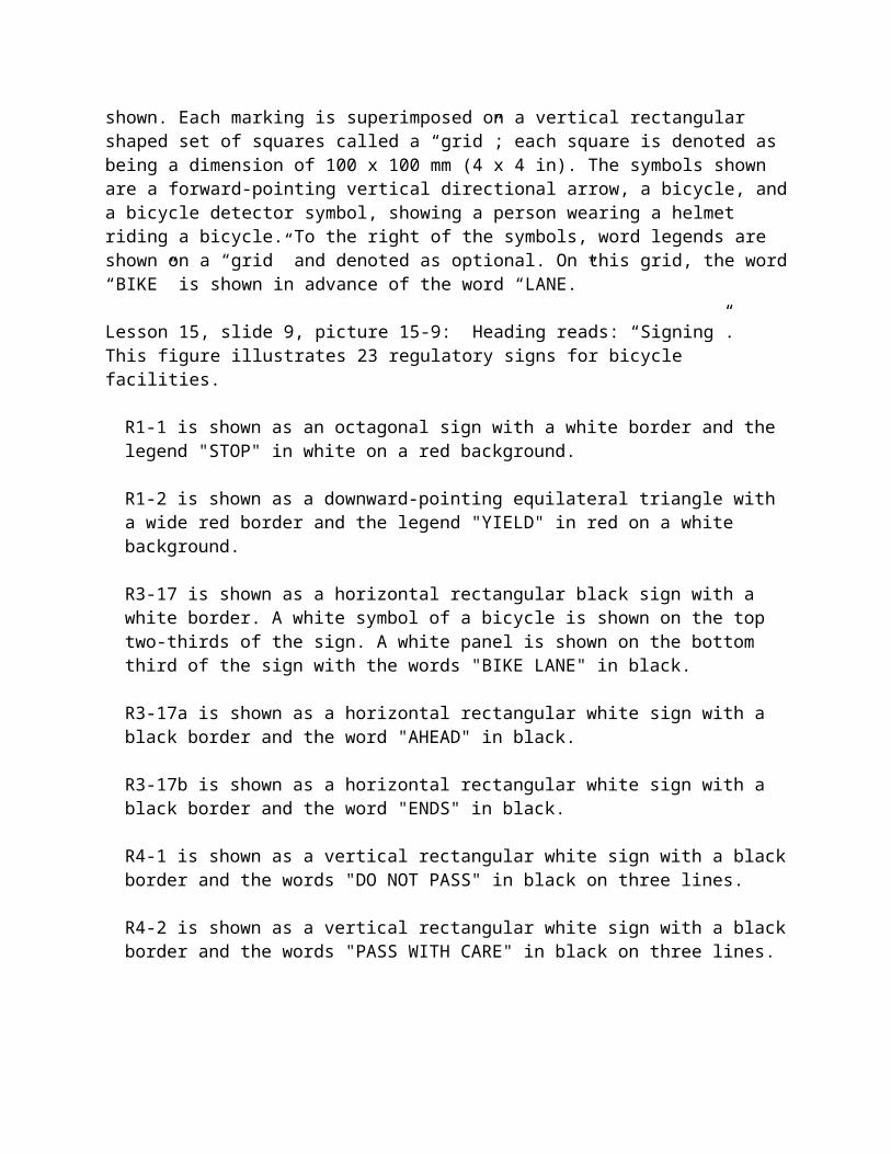
Overview, slide 5 chart O-5: Heading reads: “Bicycling and Walking Levels”. This chart shows the percent of urban travel by walking and bicycling. The following percentages apply for each country: United States, 6% walk and 1% bike; Canada, 10% walk and 2% bike; England and Wales, 12% walk and 4% bike; France, 24% walk and 4% bike; Italy, 24% walk and 4% bike; Switzerland, 24% walk and 10% bike; Germany, 22% walk and 12% bike; Austria, 28% walk and 9% bike; Sweden, 29% walk and 10% bike; Denmark, 21% walk and 20% bike; and Netherlands, 18% walk and 28% bike.
Overview, slide 9 picture O-9: Heading reads: “Environment”. Picture shows cars on a narrow, one-way traffic road. There is a bike lane and one cyclist rides in the distance.
Overview, slide 10 picture O-10: Heading reads: “Health Benefits”. There are two pictures. The top picture shows 10 people in a crosswalk, crossing a city street. The second picture shows a crossing guard in a crosswalk, helping a few school children and their parents cross the street.
Overview, slide 11 chart O-11: Heading reads: “Health Issues”. Graphic showing chart with timeline that illustrates that in recent years, the percentage of children who make trips on foot has decreased, while overweight children have increased significantly. The caption reads: “35% of youth do not participate in regular physical activity.”
Overview, slide 14 picture O-14: Heading reads: “Distance/Time – Land Use Separation”. The picture shows an aerial view of a suburban cul-de-sac neighborhood. The development is surrounded by a large forest area. There are no pedestrian connections between the ends of the cul de sacs, and one would have a long way to walk or bike to the main street.
Overview, slide 15 picture O-15: Heading reads: “Safety Concerns”. The picture shows a photo of a boy, standing on the yellow line in the middle of a road, attempting to make a mid block crossing in busy two-way traffic.
Overview, slide 17 picture O-17: Heading reads: “Trip Barriers”. There are three pictures on the slide. The picture on the left is of an elderly woman standing at the curb, waiting to cross the street. She is standing at the end of a very long crosswalk with no crossing refuge in the middle. The next picture on the top right is of a person riding a bicycle on the narrow paved shoulder of a busy country road. The bottom picture is of a crossing triangle at the end of a crosswalk. It has a call button for the crosswalk, but the triangle is overgrown with wild plants and brambles.
Overview, slide 18 picture O-18: Heading reads: “Trip Barriers”. There are two pictures. First picture shows a road with trees on one side and utility poles and guard rail on the other side. Pedestrians have worn a dirt path into the one foot wide strip between the guard rail that runs in front of the utility poles and the curb. A pedestrian is shown walking precariously on the path. Second picture shows a wide urban arterial street in a strip shopping area. There are three lanes of traffic each direction with a center turning lane. The road is very wide, and two men are shown crossing the street, striding across the center turn lane.
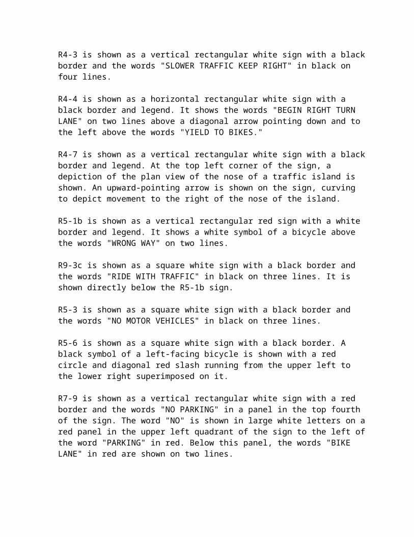
Overview, slide 19 picture O-19: Heading reads: “Destination Barriers”. There are two pictures. The picture on the left is an aerial view of a parking lot of a shopping center. The parking lot is half filled with cars. In order to get to the shopping area, someone must park and walk through the parking area. The picture on the right is a photo of the entry drive of a drive-thru coffee restaurant.
Overview, slide 21 picture O-21: Heading reads: “Kentlands, MD”. Picture is of a lovely suburban neighborhood with a tree lined street, well tended yards and a wide brick paved sidewalk in front of the houses. There are no garages visible. There are a couple cars parked along the shaded street and a child is walking on the sidewalk in a direction away from the camera.
Overview, slide 22 picture O-22: Heading reads: “Building Orientation”. Picture shows an 8-12’ sidewalk in front of stores. There are trees, large flower pots, newspaper boxes and park benches, narrowing the walking area. There is a child on a scooter and three women holding coffee cups and chatting outside one of the shops.
Overview, slide 23 picture O-23: Heading reads: “On-Site Circulation”. The picture shows a sunken patio area with café tables in what looks like a new shopping center. Parking does not come right up to the doors of the shops. There is a covered pergola area enclosing the patio, and the shop entrances are under this covered area. The picture shows numerous groups of people sitting on a wall separation of the patio, and others seated around tables.
Overview, slide 24 picture O-24: Heading reads: “Development Connections”. The picture shows a new-looking shopping development with a gateway structure between buildings. By creating a landmark the connection to the parking area is easier to find.
Overview, slide 25 picture O-25: Heading reads: “Creative Parking Lot Design”. The picture shows a tree lined sidewalk that is lavishly landscaped on both sides. The sidewalk area forms a buffer between what looks to be the roadway into a commercial area on the left and a parking lot on the right.
Overview, slide 26 picture O-26: Heading reads: “Cul-de-sacs”. Picture shows houses facing the cul-de-sac. There is a sidewalk off the end of the cul-de-sac that leads to another cul-de-sac, allowing pedestrian traffic flow.
Overview, slide 27 picture O-27: Heading reads: “Pedestrian Facilities”. Picture shows two adults with six children crossing the street in a wide crosswalk. An adult crossing guard is assisting the group by holding a stop sign to stop traffic.
Overview, slide 29 picture O-29: Heading reads: “Sidewalk Width”. This picture shows several people walking along a wide sidewalk.
Overview, slide 30 picture O-30: Heading reads: “Border Areas and Buffers”. This slide has two pictures to illustrate examples of landscaping used to separate the street from the sidewalk. In the picture on the left, a solid hedge with intermittent trees is used to provide a continuous
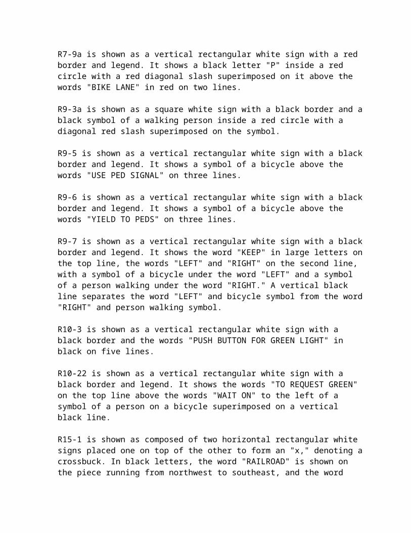
buffer between the sidewalk and the street. In the picture on the right, grass with periodic palm trees is used in this buffer space.
Overview, slide 31 picture O-31: Heading reads: “Crosswalk Markings”. This figure has six different crosswalk patterns. The first, Solid, is a filled-in rectangle; the second, Standard, is two parallel lines running vertically; the third, Continental, has seven thick lines running horizontally; the fourth, Dashed, has two dashed lines parallel to each other running vertically; the fifth, Zebra, has two parallel lines running vertically with diagonal lines inside the outer two; and the sixth, Ladder, has two parallel lines running vertically and six thick lines running horizontally inside the other two (like a combination of the Standard and the Continental together).
Overview, slide 34 picture O-34: Heading reads: “Median Refuge Island and Curb Extension”. 1) Midblock crossing curb extensions provide better visibility for motorists and pedestrians. In this figure, two lanes of traffic are moving in each direction, divided by a landscaped median. There is a bike lane and a lane for parallel parking on the far outsides of the street in both directions. At a midblock crossing point, with a continental-style crosswalk pattern and lit by street lights, there is a curb extension which juts out to the end of the parking lane, not restricting the bike lane. This allows for pedestrians to have a shorter crossing distance across the roadway. 2) This photo shows a two-lane road with a curb extension and a crosswalk with no signal or intersection nearby.
Overview, slide 35 picture O-35: Heading reads: “In-Roadway Warning Lights”. This photo shows a view from the sky of a zebra crossing (two parallel lines running perpendicular to the roadway with diagonal lines inside the outer two) with in-roadway warning lights located on the outside of the crosswalk.
Overview, slide 36 picture O-36: Heading reads: “Pedestrians with Different Needs”. There are two pictures on this slide. The first picture in the bottom left shows a man in a wheelchair being assisted by another adult. The second picture on the right of the slide shows a woman with an arm-braced cane crossing a street with the assistance of another adult.
Overview, slide 38 picture O-38: Heading reads: “Sidewalks”. This slide shows two pictures of sidewalks in different environments. The picture on the left shows a sidewalk in a park environment. The picture on the right shows a sidewalk between and street and store fronts, and benches, street trees and streetside bollards are also in this sidewalk space.
Overview, slide 39 picture O-39: Heading reads: “Curb Ramps”. This slide shows three pictures to illustrate different types of pedestrian curb ramps.
Overview, slide 40 picture O-40: Heading reads: “Pushbuttons”. This slide shows three pictures to illustrate different types of pushbuttons. The picture on the left shows a close-up view of a pushbutton and supplemental plaque that says “PUSH BUTTON FOR CORSSWALK WARNING DEVICE – CROSS WITH CAUTION”. The picture in the middle has an elderly woman standing and pressing a pushbutton. The picture on the right shows a close-up view of a pushbutton and supplemental plaque that has three panels stacked horizontally. The top one has a
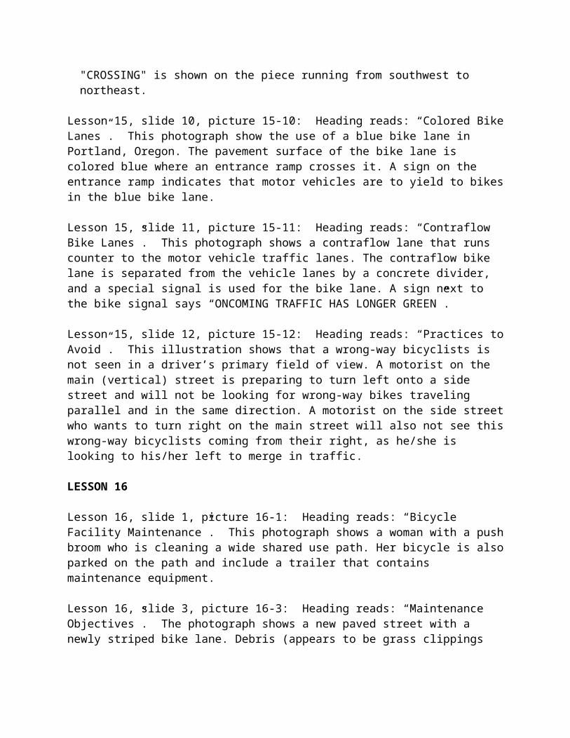
box with a person walking, and to the side, the instructions, “START CROSSING. WATCH FOR TURNING CARS” The middle panel of the plaque has a box with a hand in it, the word “FLASHING” over it, and the instructions, “DON’T START. FINISH CROSSING IF STARTED” The bottom panel has a box with a hand in it, the word “STEADY” over it, and the instructions, “PEDESTRIANS SHOULD NOT BE IN CROSSWALK”.
Overview, slide 41 picture O-41: Heading reads: “Bicycle Facilities”. This photograph shows a bicyclist riding in a bike lane, which is separated from the vehicle travel lane by a solid white tranverse pavement marking. A bike symbol pavement marking is also visible in the bike lane.
Overview, slide 42 picture O-42: Heading reads: “Bicyclist Skill Levels Affect Design”. This slide contains three pictures that illustrate different categories of bicyclists. The picture on the left shows an advanced bicyclist, or Type A bicyclist. The picture in the middle shows a Type B, or basic, bicyclist. The picture on the right shows several Type C (children) bicyclists.
Overview, slide 43 picture O-43: Heading reads: “Bicycle Facility Types”. 1) This photograph shows a bicyclist riding in the right third of a vehicle lane, and a vehicle has crossed the roadway centerline in order to pass the bicyclist. 2) This photograph shows two bicyclists riding single file in a wide curb lane. Vehicles are passing the bicyclists in the same lane but are not crossing the road centerline.
Overview, slide 44 picture O-44: Heading reads: “Bicycle Facility Types”. 1) This photograph shows a bicyclist riding in a bike lane, which is separated from the vehicle travel lane by a solid white tranverse pavement marking. A bike symbol pavement marking is also visible in the bike lane. 2) This photograph shows a shared use path that has a pedestrian area separated from a bicyclist area by a solid white line. The bicyclist area on the path is divided into two opposing directions by a white dashed line.
Overview, slide 48 picture O-48: Heading reads: “Bicycle Level of Service A”. The picture shows a 4-lane road, two lanes in both directions, passing cornfields. The road has a paved 9’ shoulder, and a bicyclist is riding towards the camera.
Overview, slide 49 picture O-49: Heading reads: “Bicycle Level of Service E”. The picture shows a cyclist riding on the 1 foot paved shoulder of a busy two lane suburban road. There is a truck approaching the cyclist from behind and in order for the cars to pass the cyclist, they must cross the solid yellow center line.
Overview, slide 51 picture O-51: Heading reads: “Retrofitting Bike Lanes”. This illustration shows a before-and-after street configuration in which a two-way, four-lane street is changed to two lanes, a two-way left turn lane, and two bike lanes. The before condition has the following cross section and dimensions (from left to right): four motor vehicle travel lanes (two in each direction) that are each 3.6 m (12 ft). The after condition has the following cross section and dimensions (from left to right): bike lane of 1.8 m (6 ft); travel lane of 3.6 m (12 ft); two-way left turn lane or median of 3.6 m (12 ft); travel lane of 3.6 m (12 ft); and bike lane of 1.8 m (6 ft).
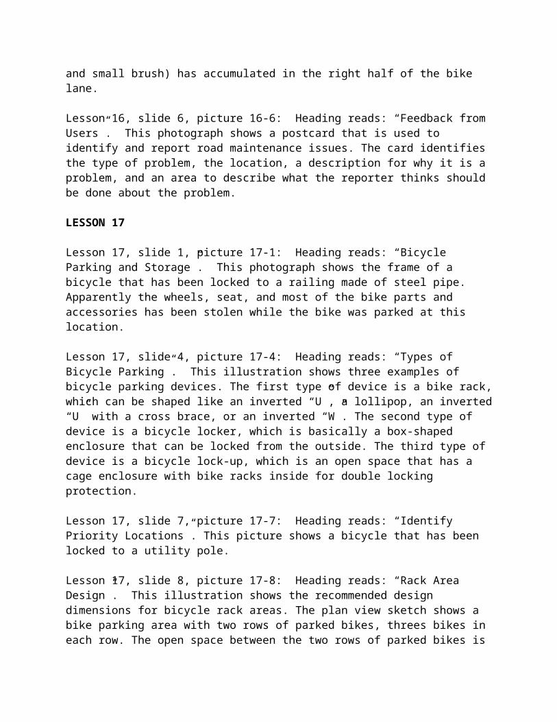
Overview, slide 52 picture O-52: Heading reads: “Road Diet”. This slides shows a before and after picture of a street that has undergone a road diet. The leftmost picture shows an aging main street. There are wide sidewalks in front of shops. There are four wide traffic lanes as well as parking on both sides of the street. There are no trees or landscaping. The rightmost picture shows the same street as the previous picture, but with improvements. There are now two travel lanes with on street parking. Bike lanes have been added. Left and right turn lanes have been added at intersections. The center lane is now a turn lane and has stripes running across it to deter travel in that lane.
Overview, slide 53 picture O-53: Heading reads: “Bicycle Boulevards”. This picture shows a bicyclist and pedestrian traveling along a bicycle boulevard. At the intersection, motor vehicle traffic is not permitted to travel straight across the intersection. Instead, motor vehicle traffic is forced to turn right.
Overview, slide 54 picture O-54: Heading reads: “Contraflow Bike Lanes”. This photograph shows a contraflow lane that runs counter to the motor vehicle traffic lanes. The contraflow bike lane is separated from the vehicle lanes by a concrete divider, and a special signal is used for the bike lane. A sign next to the bike signal says “ONCOMING TRAFFIC HAS LONGER GREEN”.Overview, slide 55 picture O-55: Heading reads: “Colored Bike Lanes”. This photograph show the use of a blue bike lane in Portland, Oregon. The pavement surface of the bike lane is colored blue where an entrance ramp crosses it. A sign on the entrance ramp indicates that motor vehicles are to yield to bikes in the blue bike lane.
Overview, slide 57 picture O-57: Heading reads: “Drainage Grates”. This illustration shows three different styles of bicycle-safe grates. The first style has a honeycomb pattern. The second style has a grate pattern in which the slots are perpendicular to the direction of bike travel. The third style has a grate pattern in which the slots are parallel to the direction of bike travel, but there are cross spacers that limit the maximum slot length to 150 mm (6 in).
Overview, slide 58 picture O-58: Heading reads: “Railroad Crossings”. This illustration is a plan view that shows how a bike lane or shoulder can be made to cross a skewed railroad track at an acceptable angle (no less than 60 degrees). A 9 m (30 ft) radius curve is used to better align the bike lane to cross perpendicular to the tracks, and a 1.2 m (4 ft) tangent section is provided before and after the tracks to allow bike to cross tracks with both wheels straight. The entire length of the “jughandle” configuration is 22.8 m (76 ft) and width is 4.8 m (16 ft).
Overview, slide 59 picture O-59: Heading reads: “Rumble Strips”. This picture shows a bike lane which has rumble strips along the left edge. Accompanying text says “AVOID THIS! (rumble strips in bike lane)”.
Overview, slide 60 picture O-60: Heading reads: “Introduction to Shared Use Paths”. Picture shows a seaside multi-use path. The path is divided down the center and there are directional arrows to aid traffic flow. On the right side of the path, two people are walking and a rollerblader is passing them on their left, and on the left (or oncoming lane) is a bicyclist.
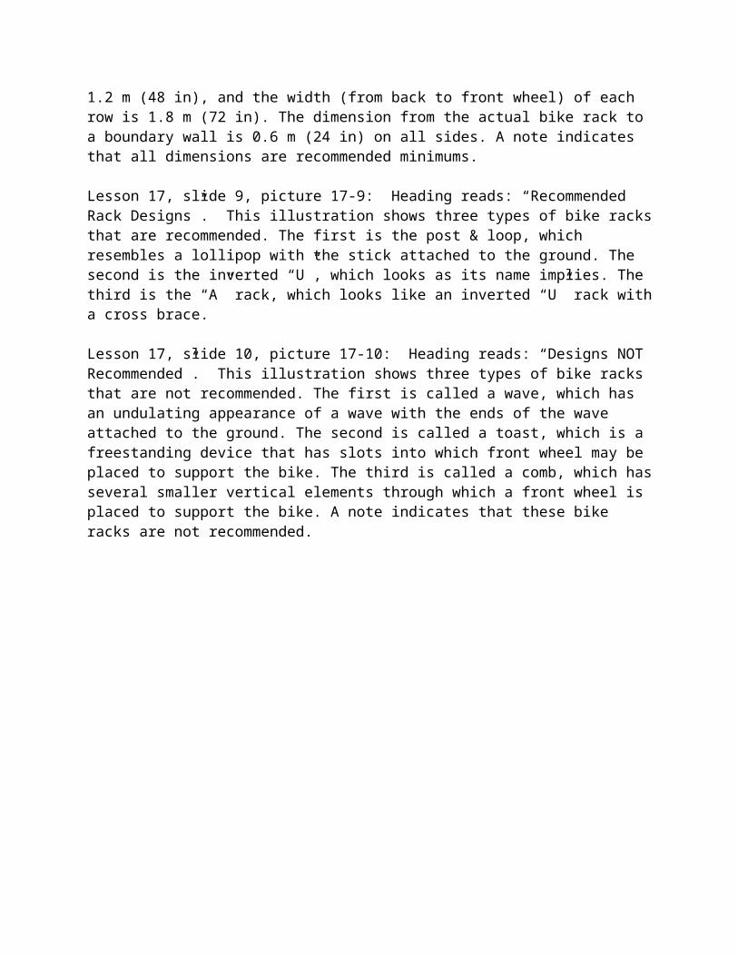
Overview, slide 61 picture O-61: Heading reads: “Users of Shared Use Paths”. There are three pictures in this slide. First picture shows a man on a motorized scooter. Second picture shows a father and child on a tandem bike pulling a second child in a trail-a-bike. The third picture shows two children on scooters. All the cyclists and scooter riders are wearing helmets.
Overview, slide 62 picture O-62: Heading reads: “Shared Use Path Design”. There are two pictures and a graphic. The graphic shows a cross section drawing of a bike path: Signage is placed three feet away from the pavement, the path is ten feet wide with a two percent cross slope. A centerline is optional, and on either side is a minimum two foot wide shoulder sloping down from the path. The fist picture shows a wheelchair lift for a pedestrian overpass. The second shows a wide crosswalk with striping.
Overview, slide 63 picture O-63: Heading reads: “Trail Design Issues”. Five pictures show trail elements. 1.) A picture of a tunnel that conveys a trail beneath a road. 2.) A “Yield to Bikes” sign. 3.) A town limit sign. 4.) A historic marker describing an event in the trails vicinity. 5.) A bronze plate used as a place marker for a significant site.
Overview, slide 65 picture O-65: Heading reads: “Pedestrian Connections to Transit”. There are two pictures. The first picture shows a woman sitting on the curb of the road waiting for a bus. There is no sidewalk, only a paved shoulder. The second picture shows a bus stop with a sidewalk and a bench between two trees. The bench was placed there by the Lion’s Club. There is a bus stop sign in the grass strip between the sidewalk and the curb.
Overview, slide 66 picture O-66: Heading reads: “Bicycle-on-Bus Programs”. Picture shows a man loading a bicycle onto a front rack of a city bus.
Overview, slide 67 picture O-67: Heading reads: “Bicycle-on-Rail Programs”. Picture shows a man with a bicycle riding in a subway car.
Overview, slide 68 picture O-68: Heading reads: “Types of Bicycle Parking”. This illustration shows three examples of bicycle parking devices. The first type of device is a bike rack, which can be shaped like an inverted “U”, a lollipop, an inverted “U” with a cross brace, or an inverted “W”. The second type of device is a bicycle locker, which is basically a box-shaped enclosure that can be locked from the outside. The third type of device is a bicycle lock-up, which is an open space that has a cage enclosure with bike racks inside for double locking protection.
Overview, slide 69 picture O-69: Heading reads: “Recommended Rack Designs”. This illustration shows three types of bike racks that are recommended. The first is the post & loop, which resembles a lollipop with the stick attached to the ground. The second is the inverted “U”, which looks as its name implies. The third is the “A” rack, which looks like an inverted “U” rack with a cross brace.
Overview, slide 70 picture O-70: Heading reads: “Designs NOT Recommended”. This illustration shows three types of bike racks that are not recommended. The first is called a wave, which has an undulating appearance of a wave with the ends of the wave attached to the ground. The second is called a toast, which is a freestanding device that has slots into which front wheel
may be placed to support the bike. The third is called a comb, which has several smaller vertical elements through which a front wheel is placed to support the bike. A note indicates that these bike racks are not recommended.
Overview, slide 71 picture O-71: Heading reads: “Comprehensive Approach”. The photograph shows five adults sitting around a table and discussing issues. All people are intently listening to the person speaking.
Overview, slide 72 picture O-72: Heading reads: “Education Strategies”. The photograph shows two young children on bikes being instructed by a standing adult. The adult and children appear to be standing in a bike safety course.
Overview, slide 73 picture O-73: Heading reads: “Enforcement Strategies”. The photograph shows a CD-ROM entitled “Resource Guide on Laws Related to Pedestrian and Bicycle Safety.” The DOT and NHTSA logo are seen on the front of the CD-ROM.
Overview, slide 74 picture O-74: Heading reads: “Encouragement Strategies”. The picture shows a male and female adult jogging on a shared use trail.


