Lensless Photography with only an image sensor
16
a) Correspondence and requests for materials should be addressed to R. M. ([email protected]) Lensless Photography with only an image sensor Ganghun Kim, 1 Kyle Isaacson, 2 Racheal Palmer, 2 Rajesh Menon 1 , a) 1 Department of Electrical and Computer Engineering, University of Utah, Salt Lake City, 84111, USA 2 Department of Bioengineering, University of Utah, Salt Lake City, 84111, USA *Corresponding author: [email protected] Photography usually requires optics in conjunction with a recording device (an image sensor). Eliminating the optics could lead to new form factors for cameras. Here, we report a simple demonstration of imaging using a bare CMOS sensor that utilizes computation. The technique relies on the space variant point-spread functions resulting from the interaction of a point source in the field of view with the image sensor. These space-variant point-spread functions are combined with a reconstruction algorithm in order to image simple objects displayed on a discrete LED array as well as on an LCD screen. We extended the approach to video imaging at the native frame rate of the sensor. Finally, we performed experiments to analyze the parametric impact of the object distance. Improving the sensor designs and reconstruction algorithms can lead to useful cameras without optics. The optical systems of cameras in mobile devices typically constrain the overall thickness of the devices 1-2 . By eliminating the optics, it is possible to create ultra-thin cameras with interesting new form factors. Previous work in computational photography has eliminated the need for lenses by utilizing apertures in front of the image sensor 3-7 or via coherent illumination of the sample 8 . In the former case, the apertures create shadow patterns on the sensor that could be computationally recovered by solving a linear inverse problem 9 . The latter case requires coherent illumination, which is not generally applicable to imaging. In most instances, coded apertures have replaced the lenses. Microfabricated coded apertures have recently shown potential for the thinner systems, 4 with thickness on the order of millimeters. However, these apertures are absorbing and hence, exhibit relatively low transmission efficiencies. Another method utilizes holographic phase masks integrated onto the image sensor in conjunction with computation to enable simple imaging. 10,11 In this case, precise microfabrication of the mask onto the sensor is required. Another computational camera utilizes a microlens array to form a large number of partial images of the scene, which is then numerically combined to form a single image with computational refocusing 12-14 . Here, we report on a computational camera that is comprised of only a conventional image sensor and no other elements. Our motivation for this camera is based upon the recognition that all cameras essentially rely on the fact that the information about the object enters the aperture of the lens, the coded aperture or micro-lens array, and is recorded by the image sensor. In the case of the coded aperture and the microlens array, numerical processing is performed to represent the image for human consumption. If all optical elements are eliminated, the information from the object is still recorded by the image sensor. If appropriate reconstruction algorithms were developed, the image recorded by the sensor can be subsequently recovered for human consumption. It is analogous the multi-sensory compressive sensing 6 where spatial light
Transcript of Lensless Photography with only an image sensor
a) Correspondence and requests for materials should be addressed to R. M. ([email protected])
Lensless Photography with only an image sensor
Ganghun Kim,1 Kyle Isaacson,2 Racheal Palmer,2 Rajesh Menon1,a)
1Department of Electrical and Computer Engineering, University of Utah, Salt Lake City, 84111, USA 2Department of Bioengineering, University of Utah, Salt Lake City, 84111, USA
*Corresponding author: [email protected]
Photographyusuallyrequiresopticsinconjunctionwitharecordingdevice(animagesensor).Eliminatingtheopticscouldleadtonew
formfactorsforcameras.Here,wereportasimpledemonstrationofimagingusingabareCMOSsensorthatutilizescomputation.The
techniquereliesonthespacevariantpoint-spreadfunctionsresultingfromtheinteractionofapointsourceinthefieldofviewwiththe
imagesensor.Thesespace-variantpoint-spreadfunctionsarecombinedwithareconstructionalgorithminordertoimagesimpleobjects
displayedonadiscreteLEDarrayaswellasonanLCDscreen.Weextendedtheapproachtovideoimagingatthenativeframerateofthe
sensor.Finally,weperformedexperimentstoanalyzetheparametric impactoftheobjectdistance. Improvingthesensordesignsand
reconstructionalgorithmscanleadtousefulcameraswithoutoptics.
Theopticalsystemsofcamerasinmobiledevicestypicallyconstraintheoverallthicknessofthedevices1-2.Byeliminatingtheoptics,itis
possibletocreateultra-thincameraswithinterestingnewformfactors.Previousworkincomputationalphotographyhaseliminatedtheneedfor
lensesbyutilizingaperturesinfrontoftheimagesensor3-7orviacoherentilluminationofthesample8.Intheformercase,theaperturescreate
shadowpatternsonthesensorthatcouldbecomputationallyrecoveredbysolvingalinearinverseproblem9.Thelattercaserequirescoherent
illumination,which isnot generally applicable to imaging. Inmost instances, codedapertureshave replaced the lenses.Microfabricated coded
apertures have recently shown potential for the thinner systems,4 with thickness on the order ofmillimeters. However, these apertures are
absorbingandhence,exhibitrelativelylowtransmissionefficiencies.Anothermethodutilizesholographicphasemasksintegratedontotheimage
sensorinconjunctionwithcomputationtoenablesimpleimaging.10,11Inthiscase,precisemicrofabricationofthemaskontothesensorisrequired.
Anothercomputationalcamerautilizesamicrolensarraytoformalargenumberofpartialimagesofthescene,whichisthennumericallycombined
toformasingleimagewithcomputationalrefocusing12-14.Here,wereportonacomputationalcamerathatiscomprisedofonlyaconventionalimage
sensorandnootherelements.
Ourmotivationforthiscameraisbasedupontherecognitionthatallcamerasessentiallyrelyonthefactthattheinformationaboutthe
objectenterstheapertureofthelens,thecodedapertureormicro-lensarray,andisrecordedbytheimagesensor.Inthecaseofthecodedaperture
andthemicrolensarray,numericalprocessingisperformedtorepresenttheimageforhumanconsumption.Ifallopticalelementsareeliminated,
theinformationfromtheobjectisstillrecordedbytheimagesensor.Ifappropriatereconstructionalgorithmsweredeveloped,theimagerecorded
bythesensorcanbesubsequentlyrecoveredforhumanconsumption.Itisanalogousthemulti-sensorycompressivesensing6wherespatiallight

modulatorisusedtoformmultiplearbitraryaperturesinfrontofsensorarraytorecordthescene,excepttheapertureinthiscaseisasinglestatic
openaperture.
FIG.1.Experimentsetupandprinciplesofoperation.(a)PhotographofthesetupshowingLEDmatrixinfrontoftheimagesensor(top-rightinset).
(b)SensorimagesarerecordedforeachLEDinthearrayseparately.ThreeexemplarycalibrationimagesareshownatthreelocationsoftheLED
pointsource.(c)Totestimagereconstruction,asimplepatternisdisplayedontheLEDmatrix.Theimagecapturedbythesensorisinputintothe
recoveryalgorithmtoreconstructthescene.
Ourtestobjectwasa32x32RGBLEDmatrixpanel(SparkFun,COM-12584)controlledviaanArduinoboard.TheLEDsareuniformly
spacedwithagapof6.1mm.Thetotalmatrixsizeis19cmX19cm. TheimagesensorwasacommerciallyavailableCMOScolorsensor(DFM

22BUC03-LM,ImagingSource).Thesensorhas640x480pixels,eachofwhichisa6μmsquare.Themaximumsupportedframerateofthecamera
viaaUSB2.0interfaceis76framespersecond.AphotographofoursetupisshowninFig.1(a).Thesensorwasplacedatasetdistance,Dfromthe
objectasillustratedinFig.1(b).TherefreshrateoftheLEDarrayis16Hz.Weusedframeaveragingtoeliminatetheeffectofthisrefreshrateaswell
astoenhancethesignaltonoiseratiooftherawdata.
Asthefirststep,weexperimentallycalibratedtheimagingsystembyrecordingtheimageofeachLEDinthearray,formingwhatwerefer
toasthecalibrationmatrix,A.100frameswereaveragedforeachLED.Exemplaryframes(elementsofmatrix,A)areshowninFig.1(b).Extraneous
lightwasminimizedduring all experiments.Whenanarbitrarypattern isdisplayedon theLEDmatrix, the resulting sensor image is a linear
combinationoftheimagesformedbytheindividualLEDs(elementsofthecalibrationmatrix,A).Thesystemcanbedescribedas
𝑏 = 𝐴𝑥 (1)
wherexistheobject,andbisthesensorimage.CalibrationmatrixAcollectedinthissetuphasconditionnumberof10,912,which
suggeststheposedinverseproblemisill-posed,andthereforemostlylikelyfailifsolvedusingadirectmatrixinversion.Hence,wecanattemptto
solvearegularizedlinearinverseproblemtorecovertheobjectxfromthesensordatab,asformulatedbelow:
𝑥 = argmin 𝐴𝑥 − 𝑏 -- + 𝛼- 𝑥 -
- (2)
whereargminrefers to theL2minimization.The regularizationparameter,αcontrolsnoise suppressionand thesmoothnessof the
solution,x.Regularizationprovidesrobustreconstructioncapabilitythatcanwithstandreasonable levelofnoise,asevidencedbythefollowing
demonstrationsoftheexperimentalcondition.
SinceourLEDmatrixhasgreenLEDs,weusedonlythegreenchannelinourexperiments.Butourtechniqueiseasilyextendedtoall
colors.Notethattheexposuretimewaschosenbetween10msand100mstoensurethatthesensorpixelswerenotsaturated.Foreachimage,100
frameswereaveraged.AnexampleoftherawsensorimageandthereconstructedimageareshowninFig.1(c),wheretheobjectistheletter,“T”.
MoreinterestingobjectsareillustratedinFig.2,wherethefirstcolumnshowsthephotographsoftheLEDmatrixusingaconventionalcamera,the
secondcolumnshowstherawsensorimages,andthethirdandfourthcolumnsshowthereconstructedimagesbeforeandafterthresholding.
Usingthissametechnique,wecanperformvideoimagingaswell,asillustratedbyanexamplevideoofajumpingstick-manincludedas
supplementaryvideo1.Thereconstructionprocess,includingallnecessaryimageprocessing,takeslessthan10msperframeusingaregular
desktopPC(IntelCorei7-4790,32GBmemory).Inourcurrentimplementation,theframeratewaslimitedbyouraveragingof100frames,which
takes1to10seconds.

FIG.2.Exemplaryimagestakenwithoursensor.Theleft-columnshowstheobjectsdisplayedontheLEDmatrix.The2ndcolumnshowstheraw
sensorimages.The3rdcolumnshowsthereconstructedimagesbeforeanyprocessing.Therightcolumnshowsthereconstructedimagesafter
binarythresholding.
As isexpectedfromthegeometryof thesystem, thedistancebetweentheobjectandthesensor,D is thekeyparameterthataffects
imagingcharacteristics.IfDistoosmall,thenthefieldofviewisexpectedtodecreasebecauseoflossoflight(andhence,lossofinformation)fromthe
off-axispointsintheobject.Atthesametime,ifDistoolarge,thenthereislossoflight(andhence,lossofinformation)duetothesensorintercepting
onlyasmallfractionoftheemittedlightfromeachpointontheobject.Asaresult,oneexpectsanoptimalvalueofDforimaging.Wedeterminedthis
empiricallybyanalyzingtheperformanceofthesensoratD=85mm,165mm,242mm,343mmand497mm.ForeachvalueofD,weobtainedthe
matrix,A,calculateditssingularvaluesandalsoreconstructedasampleobject(stickman)assummarizedinFig.3(a).ForeachD,wealsoestimated
thefieldofviewbymonitoringtheextentofonePSFonthesensorplane.However,weusedallthecalibratedPSFsforreconstruction.Wenoticed
thatrestrictingthecontributingpointstowithinthefieldofviewdidnotimpactthefinalimages.Wewereabletosuccessfullyrecoverobjectswith
upto32LEDsinthehorizontaldirectionand30LEDsintheverticaldirection.ThemountingplatformblockedthebottomtworowsoftheLED
matrix,which creates thediscrepancybetween thevertical andhorizontaldirections. Enhancement inLEDdiscriminationwasobservedasa
function of increasing distance and led to improved image reconstruction. For the largest value of D, itwas observed that the quality of the
reconstructiondecreasedslightly,possiblyduetothereductionofSNRintherecordedimage,astheamountofphotoncollectedwithinthesensor
surfacedecreasesquadraticallyasafunctionofdistance.
Sensor Image(640 x 480 pixels)
Object(32 x 32 LEDs)
Reconstructed Image Reconstructed ImageAfter Thresholding

Next,weimagedlinesorientedinthevertical,horizontal,anddiagonaldirectionsatthevarioussensor-matrixdistancestoaccesstheeffect
ofdistanceonthefieldofviewandreconstructionquality.TheresultsaresummarizedinFig.3(b).Reconstructionsofverticallineswerebetterthan
thoseofthehorizontallinesatalldistances.All30LEDs(2LEDswereblockedbyourholder)wereeasilyreconstructedintheverticaldirectionatall
distances.Ontheotherhand,atmostonly26LEDswerereconstructedproperlyinthehorizontaldirection.Weattributethisasymmetrytothe
geometryof thesensor,whichhas640pixels in theverticaldirectioncomparedto480 in thehorizontaldirection.Longerdiagonal lineswere
reconstructedatlargervaluesofDasindicatedbytheinsetimagesinFig.3(b).
Lastly,weperformednumericalanalysisoncalibrationmatrixAbasedonsingularvaluedecomposition.First,wecomparedsingular-
value-decayplotforthecalibrationmatrix,AateachvalueofD.Thisplotisanindicationofhowill-posedtheinverseproblemis15.Notethatthe
singular-value-decayplotiscomputedfromthesamecalibrationdatasetusedtoreconstructtheimages.ThisplotshowninFig.3(c)showsthatatD
=85mm,thesingularvaluesdecaymostquickly,whichisconsistentwithourexperimentalresults.Anotherwaytoestimatethedifficultyofimage
reconstructionisbyanalyzingthecorrelationcoefficientmap(Fig3d).EachelementinthecorrelationmatrixisthePearsoncorrelationcoefficient
betweentwocalibrationimages,indicatedbytheverticalandhorizontalindices.Thehorizontalmatrixiscreatedusingasetof32LEDsalongthe
horizontal line inthecenter.Verticalanddiagonalmatricesarecreatedinthesamemanner.Thecorrelationvaluesoftwosampledcalibration
imagesinanydirectionarealwaysnotablylowerthan1,indicatingthatnotwoimageswithinthecalibrationdatabasecloselyresembleoneanother.
Fromthisdistanceanalysis,wedeterminedthatD=343mmismostappropriateforoursetup.ReconstructionresultspresentedinFigs.2
and4werethereforeacquiredwithcalibrationmatrixcollectedatD=343mm.Inadditiontoprovidinginsightastohowthereconstructionperforms
atvaryingD,theaforementionedanalysisimpliesthepossibilitiesforcomputationalrefocusingandreconstructionof3Dinformation.Giventhe
collectionofthecalibrationdatabaseatmultipleobjectdistances,wecouldapplythesamelineardecompositionprocessusedheretouncoverthe3D
spatialinformationofthescene.Inthisexperiment,however,werestrictedourexperimentstothereconstructiononasingle2Dplane,forsimplicity.

FIG.3.Impactofobjectdistance.(a)Reconstructedimagesobtainedatvariousdistances,D.(c)Lengthofalineobjectimagedatvariousdistances,D
inthehorizontal,verticalanddiagonaldirections.InsetsshowreconstructedimagesofdiagonallinescapturedattheD=85,162,and242mm.(d)
Singular-value-decayplotofthecalibrationmatrix,AcapturedatvariousvaluesofD.(e)Correlationmatrixamongthecalibrationimagesfor
D=343mmalongthehorizontal,verticalanddiagonaldirections.
Finally,wereplacedtheLEDarraywithaliquid-crystaldisplay(LCD)asindicatedinFig.4(a).Usingthecalibrationmatrixobtainedwith
theLEDarray,wewerethenabletoreconstructobjectsdisplayedontheLCDandtheseresultsaresummarizedinFig.4.InFig.4(a),3different
geometries(allofcolorgreen,thesameastheLEDsusedforcalibration)areshown.Fig.4(b)showsastarpatternofvariouscolors,allreconstructed
computationally.Itcanbeseenthatthealgorithmhasdifficultyreconstructingtheredstar.Notethatallthereconstructionsutilizethecalibration
datafromthegreenLEDarray.Inallcases,wenotethatreconstructionsarepossible,butoflowerqualitythaninthecaseoftheLEDarray.Finally,
Fig.4(c)showshowthedistanceD(betweentheLCDandthesensor)affecttheimagingofanobjectcomprisedof2greenletters,“HI.”Itis
noteworthythatthesereconstructionswereallperformedwiththesamematrixA,obtainedatD=343mm.TheresultsinFig.4(c)indicatethatthe
depthoffieldoftheimagingsystemcanberelativelylarge,althoughmoreexperimentsarerequiredforpreciselyelucidatingthiseffect.Nevertheless,
Index100 101 102 103
Sing
ular
val
ue
10-4
10-3
10-2
10-1
100 (c) Singluar value decay plot85mm162mm242mm343mm497mm
Distance(mm)100 200 300 400 500
Max
imum
num
ber o
f LED
s
0
5
10
15
20
25
30
35(b) Line test results
HorizontalVerticalDiagonal
D = 85mm D = 165mm D = 242mm D = 343mm D = 497mm(a) Reconstruction of stickman at varying distances
Horizontal 1
0.5
(d) Correlation coefficient maps of 343mm calibration
Vertical Diagonal

thesepreliminaryresultsindicatethefeasibilityofusingjusttheimagesensorformachinevisionorsimilarapplications,whereanthropomorphic
imagequalityislessimportant.
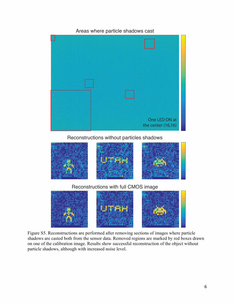
FordifferentlocationsofLEDtobediscernedbythecomputationalprocess,theremustbedistinctfeaturesintherawimagethatuniquely
differentiateseachcalibrationimagefromanother.Inthisexperiment,weobservedthreelocationsonthesensorwheresmalldustparticlescasta
scatteringpatternontothesensor.Therefore,theintensitypatternonthesensorshiftswiththelocationoftheLED.Asanexample,oneelementof
thecalibrationmatrix(theimageofoneLEDatthetop-leftcorneroftheLEDmatrix)isshowninFig.S1.Inthisframe,wenoticedthreeregionswith
scatteringpatternslikelycreatedbydustparticles(indicatedbythesquareoutlines).Ifwecloselyobserveoneoftheseregions(denotedbythered
square)forvariousframes(elementsofA,correspondingtodifferentLEDpositionsinthematrix),wecanseethatthepatternshiftswiththeposition
oftheLEDinthematrix(bottomrow).Thiswouldbethenbeconsistentwiththewell-knownpinspeckcamera16.However,ifwecloselyexaminethe
sameregionsintherawimageoftheextendedobject(withmultipleLEDs),itcanbeseenthatthesescatteringpatternsdisappearbelowthelevelof
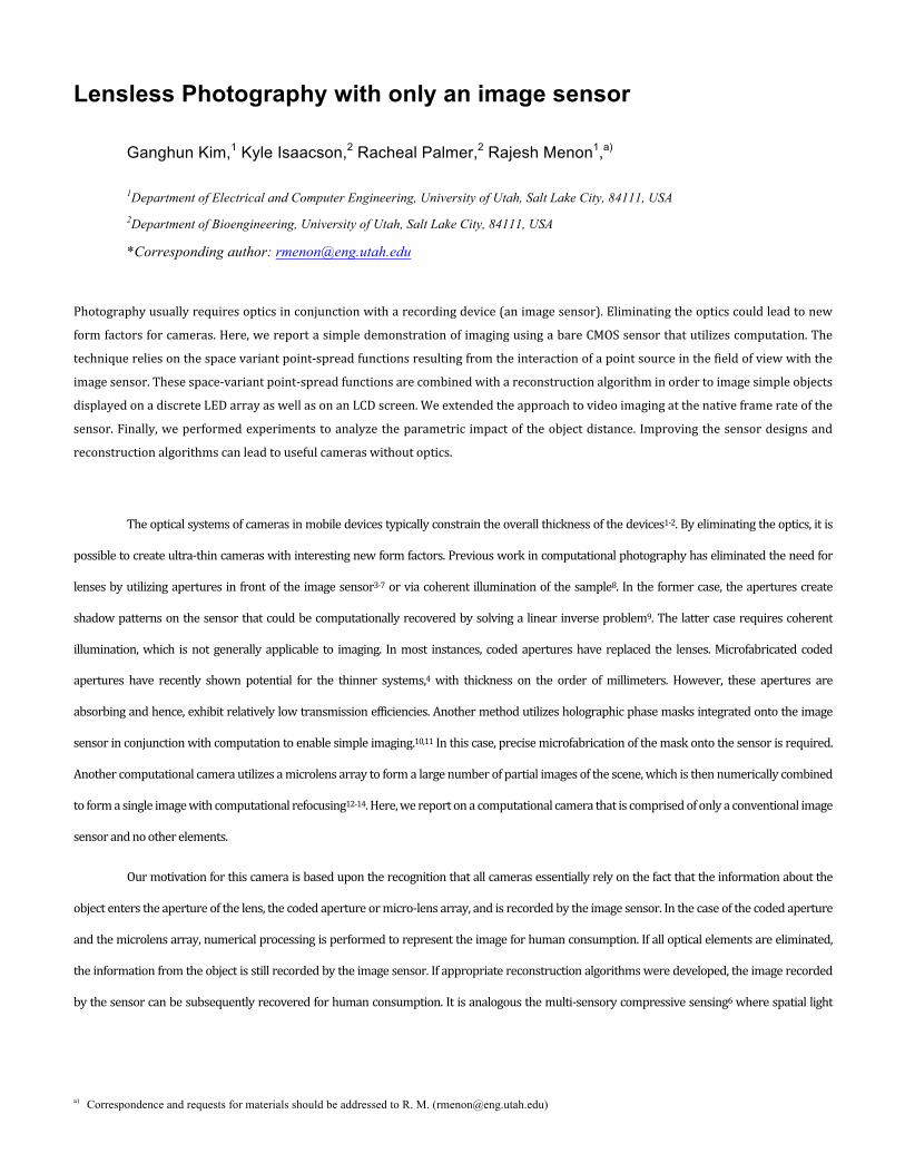
human perception as expected from the incoherent superposition of these patterns frommultiple LEDs (see Figs. S2-S4 and supplementary
information17).Therefore,ourimagingsystemclearlydifferfromconventionalpinspeckcamera.
FIG.4.ReconstructionofobjectsonLCD(iPadMini,Apple)screen.(a)PhotographofsetupandreconstructionresultsatD=343mm.(b)
Reconstructionofastarinfourdifferentcolors.Insetsshoworiginaldisplayedimages.(c)Reconstructionofword‘HI’atvaryingobjectlocations.In
allcasesincluding(c),thesamematrix,AforD=343mmwereused.

Ourhypothesisisthattheimagereconstructionissuccessfulbecauseofthecombinedeffectofthesubtleintensityvariationacrossthe
entiresensorintroducedbythediffractionandscatteringcausedbysubtledefectsandirregularitiesonthecoverglass,aswellasthefew(inourcase,
3)visiblescatteringpatternswithinthefieldofviewofthesensor.Itisimportanttonotethatclearlyscattererscouldbedirectlyengineeredontothe
sensortoenhancesuchreconstructionsinthefuture,whichwouldmakeitsimilartobutmuchmorecompactthanmask-basedlenslessimaging
methods.Suchtechniquescouldobviouslybeextendedtonon-imagingcomputationalproblemsincludinginferenceusingdeeplearningandrelated
algorithms18-19.
Inthispaper,wedescribedproof-of-conceptexperimentsthatdemonstratethat lenslessphotography ispossiblewithonlyan image
sensor.Thisisachievedviathenumericalsolutionofaninverseproblemassumingincoherenceoftheobjectandlinearityoftheimage-formation
process.Thetechniqueisappliedtobothstill-frameandvideoimaging.Bycalibratingthesystematvariousplanes,weshowthatitispossibleto
numericallyrefocusandachievequasi-3Dimagingaswell.Inotherwords,ouronly-sensorcameraisalwaysinfocus(withinlimitsofSNR).The
techniqueisreadilyextendedtocolorimaging.Furtherstudiesarenecessarytounderstandthetrade-offsrelatedtoresolution,fieldofview,depthof
fieldandothermetricsrelatedtophotography.
Funding. We gratefully acknowledge funding from the National Science Foundation (Grant # 10037833) and the Utah Science
Technology and Research Initiative. K.I was supported by a University of Utah Nanotechnology Training Program fellowship.
R.P was supported by University of Utah’s Undergraduate Research Opportunities Program.
Acknowledgments. We thank Peng Wang for his help with the regularization algorithm, and Apratim Majumder for thoughtful
discussions.
REFERENCES 1 J. Bareau and P. P. Clark, in Proceedings of International Optical Design Conference (SPIE 2006), 63421F 2 A. Bruckner and M. Schoberl, in Proceedings of MOEMS and Miniaturized Systems XII (SPIE 2013), 861617 3 T. M. Cannon and E. E. Fenimore, Opt. Eng. 19, 193283 (1980) 4 M. S. Asif, A. Ayremlou, A. Sankaranarayanan, A. Veeraraghavan and R. Baraniuk, arXiv 1509, 00116v2 (2016) 5 X. Yuan, H. Jiang, G. Huang and P. Wilford, arXiv 1508, 03498 (2015). 6 H. Jiang, G. Huang, and P. Wilford, APSIPA Transactions on Signal and Information Processing 3, e15 (2014). 7 G. Huang, H. Jiang, K. Matthews, and P. Wilford, in Proceedings of IEEE International Conference on Image Processing (IEEE, 2013), pp. 2101 8 W. Bishara,S. Mavandadi, F. W. Yu, S. Feng, R. Lau, A. Ozcan, Proc. Natl. Acad. Sci. USA 108, 7296-7301 (2011). 9 B. Adcock, A. C. Hansen, C. Poon, and B. Roman, arXiv 1302, 0561 (2014) 10 P. R. Gill and D. G. Stork, in Proceedings of Computational Optical Sensing and Imaging, Alexandria, VA, 2013 11 D. G. Stork and P. R. Gill, International Journal of Advances in Systems and Measurements, 7(3,4), 201-208 (2014) 12 J. Tanida, O. Kumagai, K. Yamada, S. Miyatake, K. Ishida, T. Morimoto, N. Kondou, D. Miyazaki, and Y. Ichioka, Appl. Opt. 40, 1806-1813 (2001) 13 K. Venkataraman, D. Lelescu, J. Duparre, A. McMahon, G. Molina, P. Chatterjee, R. Mullis and S. Nayar, ACM Trans. on Graphics. 32, 166 (2013) 14 G. Kim and R. Menon, Appl. Phys. Lett. 105, 061114 (2014)

15 A. K. Cline, C. B. Moler, G. W. Stewart, and J. H. Wilkinson, SIAM J. Numer. Anal. 16, 368-375 (1979). 16 A. L. Cohen. Optical Acta. 29(1), 63–67 (1982) 17 Supplementary Information 18 K. Kulkarni and P. Turaga, IEEE Transactions on Pattern Analysis and Machine Intelligence, 38(4), 772-784 (2016) 19 H. Chen, S. Jayasuriya, J. Yang, J. Stephen, S. Sivaramakrishnan, A. Veeraraghavan and A. Molnar, arXiv 1605, 03621 (2016).

1
Supplementary Information for Lensless Photography with only an image sensor
Ganghun Kim,1 Kyle Isaacson,2 Rajesh Menon1,a)
1Department of Electrical and Computer Engineering, University of Utah, Salt Lake City, 84111, USA 2Department of Bioengineering, University of Utah, Salt Lake City, 84111, USA
*Corresponding author: [email protected]
1. Dust and particle shadow Following four figures are enlarged copy of CMOS images presented in the main text. We marked areas where shadow appeared during the calibration procedure. Shadow completely disappears when an arbitrary object was drawn, while reconstruction was successful. Therefore, we concluded the shadow plays minor role in encoding spatial information. Images are shown in landscape orientation to maximally fit the image.

2
Figure S1. Detailed image of one LED located at the top-left corner shows 3 defects (possibly dust particles) on the sensor. These are indicated by the square outlines. The region marked with the red square is shown in the bottom for different LEDs, clearly indicating a shift of the “defect” scattering pattern.

3
Figure S2. Enlarged CMOS image of the stickman object. Photograph of the LED is shown in the inset.
Object 1. Stickman

4
Figure S3. Enlarged CMOS image of the UTAH object. Photograph of the LED is shown in the inset.
Object 2. Utah
5
Figure S4. Enlarged CMOS image of the space invader object. Photograph of the LED is shown in the inset.
Object 3. Space invader
6
Figure S5. Reconstructions are performed after removing sections of images where particle shadows are casted both from the sensor data. Removed regions are marked by red boxes drawn on one of the calibration image. Results show successful reconstruction of the object without particle shadows, although with increased noise level.
Areas where particle shadows cast
Reconstructions with full CMOS image
Reconstructions without particles shadows
One LED ON atthe center (16,16)

7
2. Imaging with CCD sensor Same imaging technique can be easily extended to other sensor type. We replaced our CMOS sensor with a CCD sensor (Clara Interline CCD, Andor) and successfully reconstructed objects displayed on LED panel.
Figure S6. Lensless imaging performed using CCD sensor array. Objects similar to ones used in CMOS imaging were reconstructed. CCD sensor we used offers higher dynamic range and lower electrical noise, which we believe lead to better reconstruction quality.
3. Supplementary Video 1 shows the animation of a jumping stick-man. Left: original scene. Center: Raw sensor video. Right: Reconstructed video.
CCD Image(1040 x 1040 pixels)
Object on LED Panel (32 x 32 pixels) Reconstructed Image