FlatCam: Thin, Lensless Cameras using Coded...
14
1 FlatCam: Thin, Lensless Cameras using Coded Aperture and Computation M. Salmnan Asif, Ali Ayremlou, Aswin Sankaranarayanan, Ashok Veeraraghavan, and Richard Baraniuk Abstract—FlatCam is a thin form-factor lensless camera that consists of a coded mask placed on top of a bare, conventional sensor array. Unlike a traditional, lens-based camera, where an image of the scene is directly recorded on the sensor pixels, each pixel in FlatCam records a linear combination of light from multiple scene elements. A computational algorithm is then used to demultiplex the recorded measurements and reconstruct an image of the scene. FlatCam is an instance of a coded aperture imaging system; however, unlike the vast majority of related work, we place the coded mask extremely close to the image sensor that enables thin and flat form-factor imaging devices. We employ a separable mask to ensure that both calibration and image reconstruction are scalable in terms of memory requirements and computational complexity. We demonstrate the potential of the FlatCam design using two prototypes: one at visible wavelengths and one at infrared wavelengths. I. I NTRODUCTION A RANGE of new imaging applications is driving the miniaturization of cameras. As a consequence, significant progress has been made towards minimizing the total volume of the camera, and this progress has enabled new applica- tions in endoscopy, pill cameras, and in vivo microscopy. Unfortunately, this strategy of miniaturization has an important shortcoming: the amount of light collected at the sensor decreases dramatically as the lens aperture and the sensor size become smaller. Therefore, ultra-miniature imagers built simply by scaling down the optics and sensors suffer from extremely low light collection. In this paper, we present a camera architecture that we call FlatCam, which is inspired by coded aperture imaging principles pioneered in astronomical X-ray and gamma-ray imaging [1]–[5]. Our proposed FlatCam design uses a large photosensitive area with a very thin form factor. FlatCam achieves thin form factor by dispensing with a lens and replac- ing it with a coded, binary mask placed almost immediately atop a bare conventional sensor array. The image formed on the sensor can be viewed as a superposition of many pinhole images. Thus, the light collection ability of such a coded aperture system is proportional to the size of the sensor and the area of the transparent regions (pinholes) in the mask. M. Asif is with the with the Department of Electrical and Computer Engineering, University of California, Riverside, CA 92501, USA e-mail: [email protected] A. Ayremlou is with Lensbricks Inc. A. Sankaranarayanan is with the Department of Electrical and Computer Engineering, Carnegie Mellon University, Pittsburgh, PA 15213, USA e-mail: [email protected] A. Veeraraghavan is with the Department of Electrical and Computer Engi- neering, Rice University, Houston, TX 77005, USA e-mail: [email protected] R. Baraniuk is with the Department of Electrical and Computer Engineer- ing, Rice University, Houston, TX 77005, USA e-mail: [email protected] An illustration of the FlatCam design is presented in Fig. 1. Light from a scene passes through a coded mask and lands on a conventional image sensor. The mask consists of opaque and transparent features (to block and transmit light, respectively); each transparent feature can be viewed as a pinhole. Light from the scene gets diffracted by the mask features such that light from each scene location casts a unique mask shadow on the sensor, and this mapping can be represented using a linear operator. A computational algorithm then inverts this linear operator to recover the original light distribution of the scene from sensor measurements. FlatCam has many attractive properties besides its slim profile. First, since it reduces the thickness of the camera but not the area of the sensor, it collects more light than miniature, lens-based cameras with same thickness. Second, the mask can be created from inexpensive materials that operate over a broad range of wavelengths. Third, the mask can be fabricated simultaneously with the sensor array, creating new manufacturing efficiencies. The mask can be fabricated either directly in one of the metal interconnect layers on top of the photosensitive layer or on a separate wafer thermal compression that is bonded to the back side of the sensor, as is typical for back-side illuminated image sensors [6]. We demonstrate the potential of FlatCam using two pro- totypes built in our laboratory with commercially available sensors and masks: a visible prototype in which the mask- sensor spacing is about 0.5mm and a short-wave infrared (SWIR) prototype in which the spacing is about 5mm. II. RELATED WORK Pinhole cameras. Imaging without a lens is not a new idea. Pinhole cameras, the progenitor of lens-based cameras, have been well known since Alhazen (965–1039AD) and Mozi (c. 370BCE). However, a tiny pinhole drastically reduces the amount of light reaching the sensor, resulting in noisy, low- quality images. Indeed, lenses were introduced into cameras for precisely the purpose of increasing the size of the aperture, and thus the light throughput, without degrading the sharpness of the acquired image. Coded aperture cameras. The primary goal of coded aper- ture cameras is to increase the light throughput compared to a pinhole camera. Coded aperture cameras extend the idea of a pinhole camera by using masks with multiple pinholes [1], [2], [4]. Figure 2 summarizes some salient features of pinhole, lens-based, and FlatCam (coded mask-based) architectures. Coded-aperture cameras have traditionally been used for imaging wavelengths beyond the visible spectrum (e.g., x- ray and gamma-ray imaging), for which lenses or mirrors
Transcript of FlatCam: Thin, Lensless Cameras using Coded...
1
FlatCam: Thin, Lensless Cameras using CodedAperture and Computation
M. Salmnan Asif, Ali Ayremlou, Aswin Sankaranarayanan, Ashok Veeraraghavan, and Richard Baraniuk
Abstract—FlatCam is a thin form-factor lensless camera thatconsists of a coded mask placed on top of a bare, conventionalsensor array. Unlike a traditional, lens-based camera, where animage of the scene is directly recorded on the sensor pixels, eachpixel in FlatCam records a linear combination of light frommultiple scene elements. A computational algorithm is then usedto demultiplex the recorded measurements and reconstruct animage of the scene. FlatCam is an instance of a coded apertureimaging system; however, unlike the vast majority of relatedwork, we place the coded mask extremely close to the imagesensor that enables thin and flat form-factor imaging devices.We employ a separable mask to ensure that both calibrationand image reconstruction are scalable in terms of memoryrequirements and computational complexity. We demonstrate thepotential of the FlatCam design using two prototypes: one atvisible wavelengths and one at infrared wavelengths.
I. INTRODUCTION
ARANGE of new imaging applications is driving theminiaturization of cameras. As a consequence, significant
progress has been made towards minimizing the total volumeof the camera, and this progress has enabled new applica-tions in endoscopy, pill cameras, and in vivo microscopy.Unfortunately, this strategy of miniaturization has an importantshortcoming: the amount of light collected at the sensordecreases dramatically as the lens aperture and the sensorsize become smaller. Therefore, ultra-miniature imagers builtsimply by scaling down the optics and sensors suffer fromextremely low light collection.
In this paper, we present a camera architecture that wecall FlatCam, which is inspired by coded aperture imagingprinciples pioneered in astronomical X-ray and gamma-rayimaging [1]–[5]. Our proposed FlatCam design uses a largephotosensitive area with a very thin form factor. FlatCamachieves thin form factor by dispensing with a lens and replac-ing it with a coded, binary mask placed almost immediatelyatop a bare conventional sensor array. The image formed onthe sensor can be viewed as a superposition of many pinholeimages. Thus, the light collection ability of such a codedaperture system is proportional to the size of the sensor andthe area of the transparent regions (pinholes) in the mask.
M. Asif is with the with the Department of Electrical and ComputerEngineering, University of California, Riverside, CA 92501, USA e-mail:[email protected]
A. Ayremlou is with Lensbricks Inc.A. Sankaranarayanan is with the Department of Electrical and Computer
Engineering, Carnegie Mellon University, Pittsburgh, PA 15213, USA e-mail:[email protected]
A. Veeraraghavan is with the Department of Electrical and Computer Engi-neering, Rice University, Houston, TX 77005, USA e-mail: [email protected]
R. Baraniuk is with the Department of Electrical and Computer Engineer-ing, Rice University, Houston, TX 77005, USA e-mail: [email protected]
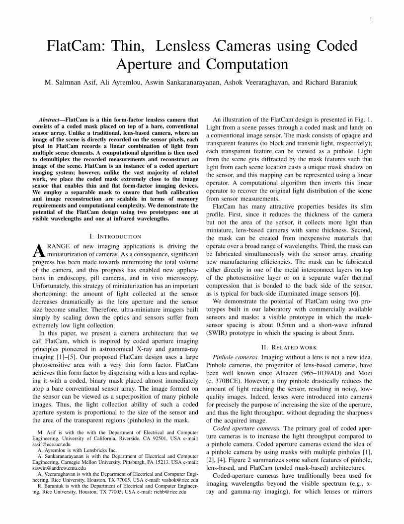
An illustration of the FlatCam design is presented in Fig. 1.Light from a scene passes through a coded mask and lands ona conventional image sensor. The mask consists of opaque andtransparent features (to block and transmit light, respectively);each transparent feature can be viewed as a pinhole. Lightfrom the scene gets diffracted by the mask features such thatlight from each scene location casts a unique mask shadow onthe sensor, and this mapping can be represented using a linearoperator. A computational algorithm then inverts this linearoperator to recover the original light distribution of the scenefrom sensor measurements.
FlatCam has many attractive properties besides its slimprofile. First, since it reduces the thickness of the camerabut not the area of the sensor, it collects more light thanminiature, lens-based cameras with same thickness. Second,the mask can be created from inexpensive materials thatoperate over a broad range of wavelengths. Third, the mask canbe fabricated simultaneously with the sensor array, creatingnew manufacturing efficiencies. The mask can be fabricatedeither directly in one of the metal interconnect layers on topof the photosensitive layer or on a separate wafer thermalcompression that is bonded to the back side of the sensor,as is typical for back-side illuminated image sensors [6].
We demonstrate the potential of FlatCam using two pro-totypes built in our laboratory with commercially availablesensors and masks: a visible prototype in which the mask-sensor spacing is about 0.5mm and a short-wave infrared(SWIR) prototype in which the spacing is about 5mm.
II. RELATED WORK
Pinhole cameras. Imaging without a lens is not a new idea.Pinhole cameras, the progenitor of lens-based cameras, havebeen well known since Alhazen (965–1039AD) and Mozi(c. 370BCE). However, a tiny pinhole drastically reduces theamount of light reaching the sensor, resulting in noisy, low-quality images. Indeed, lenses were introduced into camerasfor precisely the purpose of increasing the size of the aperture,and thus the light throughput, without degrading the sharpnessof the acquired image.
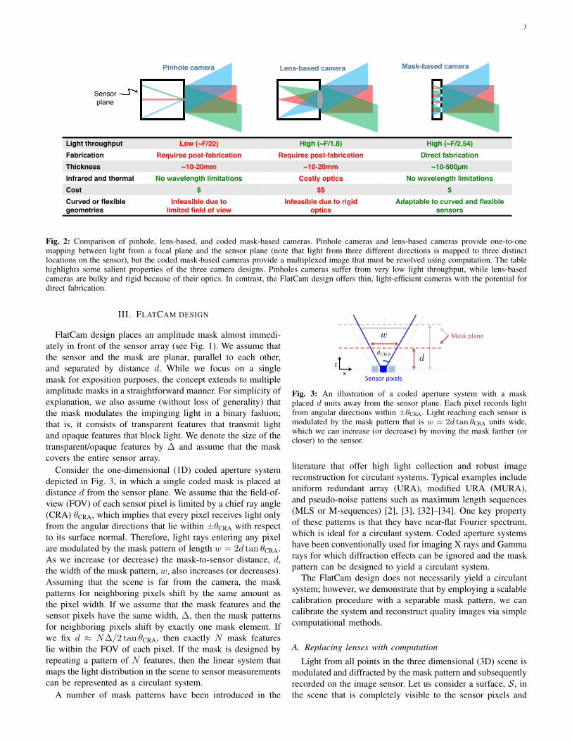
Coded aperture cameras. The primary goal of coded aper-ture cameras is to increase the light throughput compared toa pinhole camera. Coded aperture cameras extend the idea ofa pinhole camera by using masks with multiple pinholes [1],[2], [4]. Figure 2 summarizes some salient features of pinhole,lens-based, and FlatCam (coded mask-based) architectures.
Coded-aperture cameras have traditionally been used forimaging wavelengths beyond the visible spectrum (e.g., x-ray and gamma-ray imaging), for which lenses or mirrors
2
(a)!Scene!
Mask!
Sensor!
Thickness ~ 0.5mm!
Mask-sensor !assembly!
Sensor measurements! Reconstructed image!(b)!
Com
puta
tiona
l !re
cons
truc
tion!
Fig. 1: FlatCam architecture. (a) Every light source within the camera field-of-view contributes to every pixel in the multiplexed imageformed on the sensor. A computational algorithm reconstructs the image of the scene. Inset shows the mask-sensor assembly of our prototypein which a binary, coded mask is placed 0.5mm away from an off-the-shelf digital image sensor. (b) An example of sensor measurementsand the image reconstructed by solving a computational inverse problem.
are expensive or infeasible [1], [2], [4], [5], [7]. Mask-basedlens-free designs have been proposed for flexible field-of-view selection in [8], compressive single-pixel imaging using atransmissive LCD panel [9], and separable coded masks [10].
In recent years, coded masks and light modulators havebeen added to lens-based cameras in different configurationsto build novel imaging devices that can capture image anddepth [11], dynamic video [12], or 4D lightfield [13], [14]from a single coded image. Coded aperture-based systemsusing compressive sensing principles [15]–[17] have also beenstudied for image super-resolution [18], spectral imaging [19],and video capture [20].
Existing coded aperture-based lensless systems have twomain limitations: First, the large body of work devoted tocoded apertures invariably place the mask significantly faraway from the sensor (e.g., 65mm distance in [10]). In con-trast, FlatCam design offers a thin form factor. For instance,in our prototype with a visible sensor, the spacing betweenthe sensor and the mask is only 0.5mm. Second, the masksemployed in some designs have transparent features only ina small central region whose area is invariably much smallerthan the area of the sensor. In contrast, almost half of thefeatures (spread across the entire surface) in our mask aretransparent. As a consequence, the light throughput of ourdesigns are many orders of magnitude larger as compared toprevious designs. Furthermore, the lensless cameras proposedin [9], [10] use programmable spatial light modulators (SLM)and capture multiple images while changing the mask patterns.In contrast, we use a static mask in our design, which canpotentially be fixed on the sensor during fabrication or theassembly process.
Camera arrays. A number of thin imaging systems havebeen developed over the last few decades. The TOMBOarchitecture [21], inspired by insect compound eyes, reducesthe camera thickness by replacing a single, large focal-lengthlens with multiple, small focal-length microlenses. Each mi-crolens and the sensor area underneath it can be viewed asa separate low-resolution, lens-based camera, and a singlehigh-resolution image can be computationally reconstructedby fusing all of the sensor measurements. Similar architectures
have been used for designing thin infrared cameras [22]. Thecamera thickness in this design is dictated by the geometryof the microlenses; reducing the camera thickness requiresa proportional reduction in the sizes of the microlenses andsensor pixels. As a result, microlens-based cameras currentlyoffer only up to a four-fold reduction in the camera thickness[23], [24].
Folded optics. An alternate approach for achieving thinform factors relies on folded optics, where light manipulationsimilar to that of a traditional lens is achieved using multi-foldreflective optics [25]. However, folded optics based systemshave low light collection efficiencies.
Ultra-miniature lensless imaging with diffraction gratings.Recently, miniature cameras with integrated diffraction grat-ings and CMOS image sensors have been developed [26]–[29]. These cameras have been successfully demonstrated ontasks such as motion estimation and face detection. Whilethese cameras are indeed ultra-miniature in total volume (100micron sensor width by 200 micron thickness), they retainthe large thickness-to-width ratio of conventional lens-basedcameras. Because of the small sensor size, they suffer fromreduced light collection ability. In contrast, in our visibleprototype below, we used a 6.7mm wide square sensor, whichincreases the amount of light collection by about three ordersof magnitude, while the device thickness remains approxi-mately similar (500 micron).
Lensless microscopy and shadow imaging. Lensless camerashave been successfully demonstrated for several microscopyand lab-on chip application, wherein the subject to be imagedis close to the image sensor. An on-chip, lens-free microscopydesign that uses amplitude masks to cast a shadow of pointillumination sources onto a microscopic tissue sample hasshown significant promise for microscopy and related appli-cations, where the sample being imaged is very close to thesensor (less than 1mm) [30], [31]. Unfortunately, this tech-nique cannot be directly extended to traditional photographyand other applications that require larger standoff distancesand do not provide control over illumination.
3
Mask-based camera!Pinhole camera! Lens-based camera!
Sensor!plane!
Light throughput! Low (~F/22)! High (~F/1.8)! High (~F/2.54)!Fabrication! Requires post-fabrication ! Requires post-fabrication ! Direct fabrication!Thickness! ~10-20mm! ~10-20mm! ~10-500µm!Infrared and thermal! No wavelength limitations! Costly optics! No wavelength limitations!Cost! $! $$! $!Curved or flexible geometries!
Infeasible due to limited field of view!
Infeasible due to rigid !optics!
Adaptable to curved and flexible sensors!
Fig. 2: Comparison of pinhole, lens-based, and coded mask-based cameras. Pinhole cameras and lens-based cameras provide one-to-onemapping between light from a focal plane and the sensor plane (note that light from three different directions is mapped to three distinctlocations on the sensor), but the coded mask-based cameras provide a multiplexed image that must be resolved using computation. The tablehighlights some salient properties of the three camera designs. Pinholes cameras suffer from very low light throughput, while lens-basedcameras are bulky and rigid because of their optics. In contrast, the FlatCam design offers thin, light-efficient cameras with the potential fordirect fabrication.
III. FLATCAM DESIGN
FlatCam design places an amplitude mask almost immedi-ately in front of the sensor array (see Fig. 1). We assume thatthe sensor and the mask are planar, parallel to each other,and separated by distance d. While we focus on a singlemask for exposition purposes, the concept extends to multipleamplitude masks in a straightforward manner. For simplicity ofexplanation, we also assume (without loss of generality) thatthe mask modulates the impinging light in a binary fashion;that is, it consists of transparent features that transmit lightand opaque features that block light. We denote the size of thetransparent/opaque features by ∆ and assume that the maskcovers the entire sensor array.
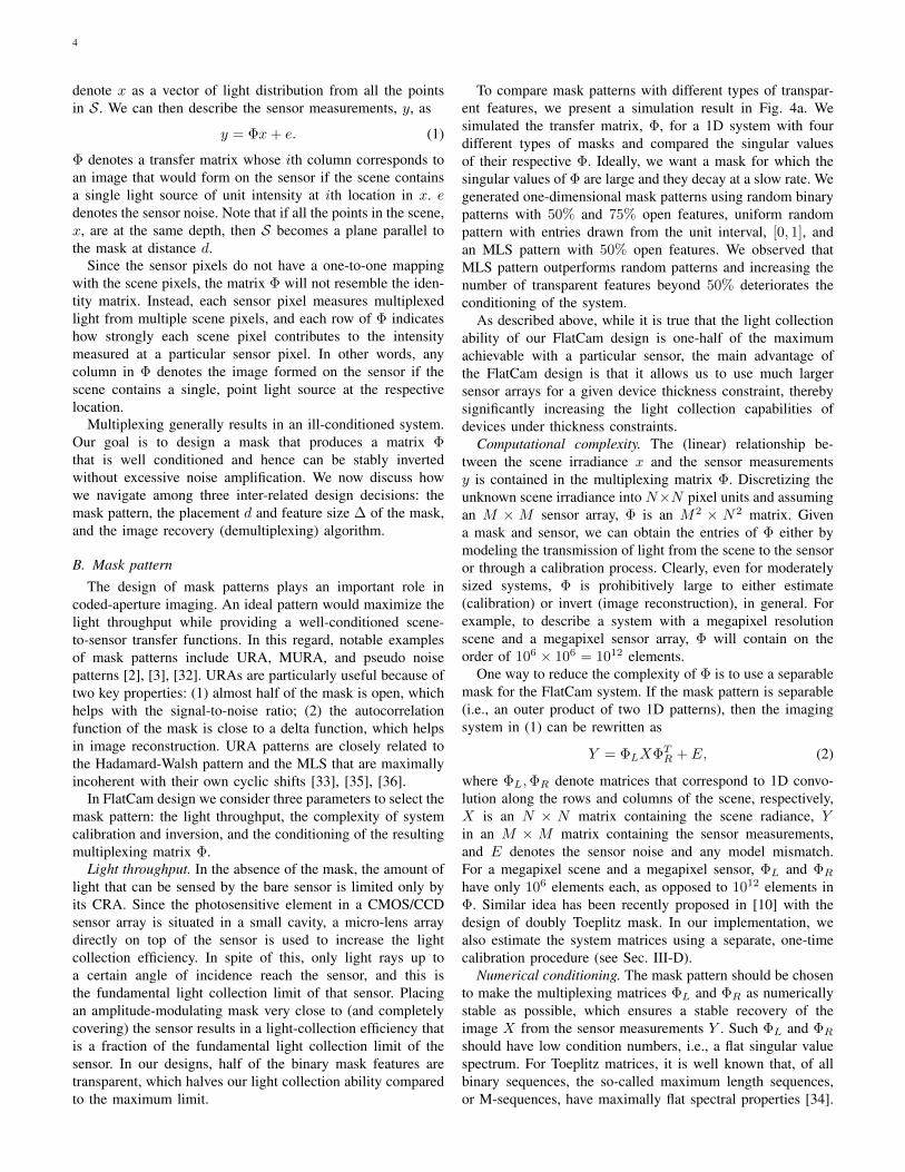
Consider the one-dimensional (1D) coded aperture systemdepicted in Fig. 3, in which a single coded mask is placed atdistance d from the sensor plane. We assume that the field-of-view (FOV) of each sensor pixel is limited by a chief ray angle(CRA) θCRA, which implies that every pixel receives light onlyfrom the angular directions that lie within ±θCRA with respectto its surface normal. Therefore, light rays entering any pixelare modulated by the mask pattern of length w = 2d tan θCRA.As we increase (or decrease) the mask-to-sensor distance, d,the width of the mask pattern, w, also increases (or decreases).Assuming that the scene is far from the camera, the maskpatterns for neighboring pixels shift by the same amount asthe pixel width. If we assume that the mask features and thesensor pixels have the same width, ∆, then the mask patternsfor neighboring pixels shift by exactly one mask element. Ifwe fix d ≈ N∆/2 tan θCRA, then exactly N mask featureslie within the FOV of each pixel. If the mask is designed byrepeating a pattern of N features, then the linear system thatmaps the light distribution in the scene to sensor measurementscan be represented as a circulant system.
A number of mask patterns have been introduced in the
✓CRA
Sensor pixels
Mask plane
d
w = 2 d tan(✓CRA)
w
x z
Fig. 3: An illustration of a coded aperture system with a maskplaced d units away from the sensor plane. Each pixel records lightfrom angular directions within ±θCRA. Light reaching each sensor ismodulated by the mask pattern that is w = 2d tan θCRA units wide,which we can increase (or decrease) by moving the mask farther (orcloser) to the sensor.
literature that offer high light collection and robust imagereconstruction for circulant systems. Typical examples includeuniform redundant array (URA), modified URA (MURA),and pseudo-noise pattens such as maximum length sequences(MLS or M-sequences) [2], [3], [32]–[34]. One key propertyof these patterns is that they have near-flat Fourier spectrum,which is ideal for a circulant system. Coded aperture systemshave been conventionally used for imaging X rays and Gammarays for which diffraction effects can be ignored and the maskpattern can be designed to yield a circulant system.
The FlatCam design does not necessarily yield a circulantsystem; however, we demonstrate that by employing a scalablecalibration procedure with a separable mask pattern, we cancalibrate the system and reconstruct quality images via simplecomputational methods.
A. Replacing lenses with computation
Light from all points in the three dimensional (3D) scene ismodulated and diffracted by the mask pattern and subsequentlyrecorded on the image sensor. Let us consider a surface, S, inthe scene that is completely visible to the sensor pixels and
4
denote x as a vector of light distribution from all the pointsin S. We can then describe the sensor measurements, y, as
y = Φx+ e. (1)
Φ denotes a transfer matrix whose ith column corresponds toan image that would form on the sensor if the scene containsa single light source of unit intensity at ith location in x. edenotes the sensor noise. Note that if all the points in the scene,x, are at the same depth, then S becomes a plane parallel tothe mask at distance d.
Since the sensor pixels do not have a one-to-one mappingwith the scene pixels, the matrix Φ will not resemble the iden-tity matrix. Instead, each sensor pixel measures multiplexedlight from multiple scene pixels, and each row of Φ indicateshow strongly each scene pixel contributes to the intensitymeasured at a particular sensor pixel. In other words, anycolumn in Φ denotes the image formed on the sensor if thescene contains a single, point light source at the respectivelocation.
Multiplexing generally results in an ill-conditioned system.Our goal is to design a mask that produces a matrix Φthat is well conditioned and hence can be stably invertedwithout excessive noise amplification. We now discuss howwe navigate among three inter-related design decisions: themask pattern, the placement d and feature size ∆ of the mask,and the image recovery (demultiplexing) algorithm.
B. Mask patternThe design of mask patterns plays an important role in
coded-aperture imaging. An ideal pattern would maximize thelight throughput while providing a well-conditioned scene-to-sensor transfer functions. In this regard, notable examplesof mask patterns include URA, MURA, and pseudo noisepatterns [2], [3], [32]. URAs are particularly useful because oftwo key properties: (1) almost half of the mask is open, whichhelps with the signal-to-noise ratio; (2) the autocorrelationfunction of the mask is close to a delta function, which helpsin image reconstruction. URA patterns are closely related tothe Hadamard-Walsh pattern and the MLS that are maximallyincoherent with their own cyclic shifts [33], [35], [36].
In FlatCam design we consider three parameters to select themask pattern: the light throughput, the complexity of systemcalibration and inversion, and the conditioning of the resultingmultiplexing matrix Φ.
Light throughput. In the absence of the mask, the amount oflight that can be sensed by the bare sensor is limited only byits CRA. Since the photosensitive element in a CMOS/CCDsensor array is situated in a small cavity, a micro-lens arraydirectly on top of the sensor is used to increase the lightcollection efficiency. In spite of this, only light rays up toa certain angle of incidence reach the sensor, and this isthe fundamental light collection limit of that sensor. Placingan amplitude-modulating mask very close to (and completelycovering) the sensor results in a light-collection efficiency thatis a fraction of the fundamental light collection limit of thesensor. In our designs, half of the binary mask features aretransparent, which halves our light collection ability comparedto the maximum limit.
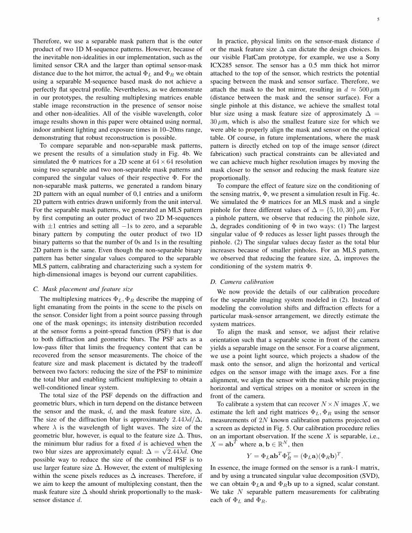
To compare mask patterns with different types of transpar-ent features, we present a simulation result in Fig. 4a. Wesimulated the transfer matrix, Φ, for a 1D system with fourdifferent types of masks and compared the singular valuesof their respective Φ. Ideally, we want a mask for which thesingular values of Φ are large and they decay at a slow rate. Wegenerated one-dimensional mask patterns using random binarypatterns with 50% and 75% open features, uniform randompattern with entries drawn from the unit interval, [0, 1], andan MLS pattern with 50% open features. We observed thatMLS pattern outperforms random patterns and increasing thenumber of transparent features beyond 50% deteriorates theconditioning of the system.
As described above, while it is true that the light collectionability of our FlatCam design is one-half of the maximumachievable with a particular sensor, the main advantage ofthe FlatCam design is that it allows us to use much largersensor arrays for a given device thickness constraint, therebysignificantly increasing the light collection capabilities ofdevices under thickness constraints.
Computational complexity. The (linear) relationship be-tween the scene irradiance x and the sensor measurementsy is contained in the multiplexing matrix Φ. Discretizing theunknown scene irradiance into N×N pixel units and assumingan M × M sensor array, Φ is an M2 × N2 matrix. Givena mask and sensor, we can obtain the entries of Φ either bymodeling the transmission of light from the scene to the sensoror through a calibration process. Clearly, even for moderatelysized systems, Φ is prohibitively large to either estimate(calibration) or invert (image reconstruction), in general. Forexample, to describe a system with a megapixel resolutionscene and a megapixel sensor array, Φ will contain on theorder of 106 × 106 = 1012 elements.
One way to reduce the complexity of Φ is to use a separablemask for the FlatCam system. If the mask pattern is separable(i.e., an outer product of two 1D patterns), then the imagingsystem in (1) can be rewritten as
Y = ΦLXΦTR + E, (2)
where ΦL,ΦR denote matrices that correspond to 1D convo-lution along the rows and columns of the scene, respectively,X is an N × N matrix containing the scene radiance, Yin an M × M matrix containing the sensor measurements,and E denotes the sensor noise and any model mismatch.For a megapixel scene and a megapixel sensor, ΦL and ΦR
have only 106 elements each, as opposed to 1012 elements inΦ. Similar idea has been recently proposed in [10] with thedesign of doubly Toeplitz mask. In our implementation, wealso estimate the system matrices using a separate, one-timecalibration procedure (see Sec. III-D).
Numerical conditioning. The mask pattern should be chosento make the multiplexing matrices ΦL and ΦR as numericallystable as possible, which ensures a stable recovery of theimage X from the sensor measurements Y . Such ΦL and ΦR
should have low condition numbers, i.e., a flat singular valuespectrum. For Toeplitz matrices, it is well known that, of allbinary sequences, the so-called maximum length sequences,or M-sequences, have maximally flat spectral properties [34].
5
Therefore, we use a separable mask pattern that is the outerproduct of two 1D M-sequence patterns. However, because ofthe inevitable non-idealities in our implementation, such as thelimited sensor CRA and the larger than optimal sensor-maskdistance due to the hot mirror, the actual ΦL and ΦR we obtainusing a separable M-sequence based mask do not achieve aperfectly flat spectral profile. Nevertheless, as we demonstratein our prototypes, the resulting multiplexing matrices enablestable image reconstruction in the presence of sensor noiseand other non-idealities. All of the visible wavelength, colorimage results shown in this paper were obtained using normal,indoor ambient lighting and exposure times in 10–20ms range,demonstrating that robust reconstruction is possible.
To compare separable and non-separable mask patterns,we present the results of a simulation study in Fig. 4b. Wesimulated the Φ matrices for a 2D scene at 64× 64 resolutionusing two separable and two non-separable mask patterns andcompared the singular values of their respective Φ. For thenon-separable mask patterns, we generated a random binary2D pattern with an equal number of 0,1 entries and a uniform2D pattern with entries drawn uniformly from the unit interval.For the separable mask patterns, we generated an MLS patternby first computing an outer product of two 2D M-sequenceswith ±1 entries and setting all −1s to zero, and a separablebinary pattern by computing the outer product of two 1Dbinary patterns so that the number of 0s and 1s in the resulting2D pattern is the same. Even though the non-separable binarypattern has better singular values compared to the separableMLS pattern, calibrating and characterizing such a system forhigh-dimensional images is beyond our current capabilities.
C. Mask placement and feature sizeThe multiplexing matrices ΦL,ΦR describe the mapping of
light emanating from the points in the scene to the pixels onthe sensor. Consider light from a point source passing throughone of the mask openings; its intensity distribution recordedat the sensor forms a point-spread function (PSF) that is dueto both diffraction and geometric blurs. The PSF acts as alow-pass filter that limits the frequency content that can berecovered from the sensor measurements. The choice of thefeature size and mask placement is dictated by the tradeoffbetween two factors: reducing the size of the PSF to minimizethe total blur and enabling sufficient multiplexing to obtain awell-conditioned linear system.
The total size of the PSF depends on the diffraction andgeometric blurs, which in turn depend on the distance betweenthe sensor and the mask, d, and the mask feature size, ∆.The size of the diffraction blur is approximately 2.44λd/∆,where λ is the wavelength of light waves. The size of thegeometric blur, however, is equal to the feature size ∆. Thus,the minimum blur radius for a fixed d is achieved when thetwo blur sizes are approximately equal: ∆ =
√2.44λd. One
possible way to reduce the size of the combined PSF is touse larger feature size ∆. However, the extent of multiplexingwithin the scene pixels reduces as ∆ increases. Therefore, ifwe aim to keep the amount of multiplexing constant, then themask feature size ∆ should shrink proportionally to the mask-sensor distance d.
In practice, physical limits on the sensor-mask distance dor the mask feature size ∆ can dictate the design choices. Inour visible FlatCam prototype, for example, we use a SonyICX285 sensor. The sensor has a 0.5 mm thick hot mirrorattached to the top of the sensor, which restricts the potentialspacing between the mask and sensor surface. Therefore, weattach the mask to the hot mirror, resulting in d ≈ 500µm(distance between the mask and the sensor surface). For asingle pinhole at this distance, we achieve the smallest totalblur size using a mask feature size of approximately ∆ =30µm, which is also the smallest feature size for which wewere able to properly align the mask and sensor on the opticaltable. Of course, in future implementations, where the maskpattern is directly etched on top of the image sensor (directfabrication) such practical constraints can be alleviated andwe can achieve much higher resolution images by moving themask closer to the sensor and reducing the mask feature sizeproportionally.
To compare the effect of feature size on the conditioning ofthe sensing matrix, Φ, we present a simulation result in Fig. 4c.We simulated the Φ matrices for an MLS mask and a singlepinhole for three different values of ∆ = {5, 10, 30}µm. Fora pinhole pattern, we observe that reducing the pinhole size,∆, degrades conditioning of Φ in two ways: (1) The largestsingular value of Φ reduces as lesser light passes through thepinhole. (2) The singular values decay faster as the total blurincreases because of smaller pinholes. For an MLS pattern,we observed that reducing the feature size, ∆, improves theconditioning of the system matrix Φ.
D. Camera calibrationWe now provide the details of our calibration procedure
for the separable imaging system modeled in (2). Instead ofmodeling the convolution shifts and diffraction effects for aparticular mask-sensor arrangement, we directly estimate thesystem matrices.
To align the mask and sensor, we adjust their relativeorientation such that a separable scene in front of the camerayields a separable image on the sensor. For a coarse alignment,we use a point light source, which projects a shadow of themask onto the sensor, and align the horizontal and verticaledges on the sensor image with the image axes. For a finealignment, we align the sensor with the mask while projectinghorizontal and vertical stripes on a monitor or screen in thefront of the camera.
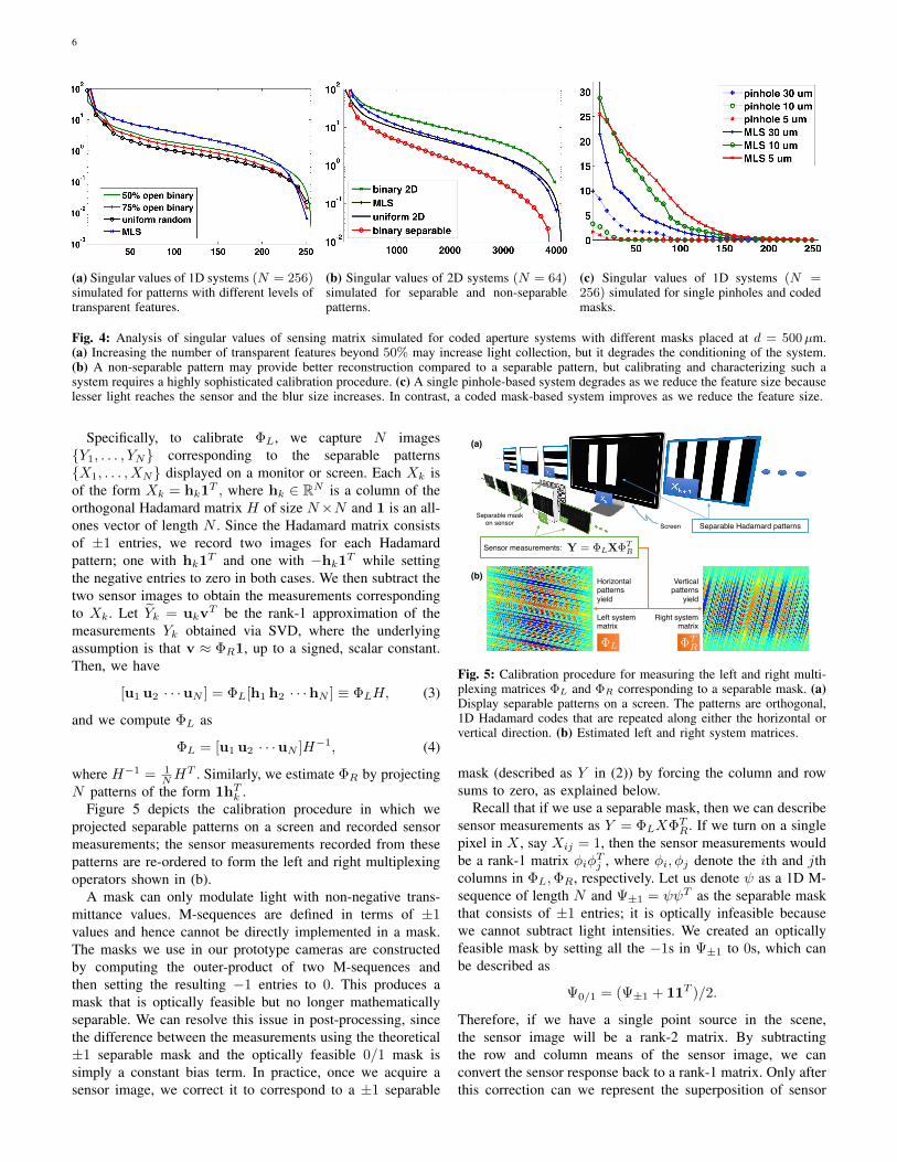
To calibrate a system that can recover N×N images X , weestimate the left and right matrices ΦL,ΦR using the sensormeasurements of 2N known calibration patterns projected ona screen as depicted in Fig. 5. Our calibration procedure relieson an important observation. If the scene X is separable, i.e.,X = abT where a,b ∈ RN , then
Y = ΦLabT ΦT
R = (ΦLa)(ΦRb)T .
In essence, the image formed on the sensor is a rank-1 matrix,and by using a truncated singular value decomposition (SVD),we can obtain ΦLa and ΦRb up to a signed, scalar constant.We take N separable pattern measurements for calibratingeach of ΦL and ΦR.
6
(a) Singular values of 1D systems (N = 256)simulated for patterns with different levels oftransparent features.
(b) Singular values of 2D systems (N = 64)simulated for separable and non-separablepatterns.
(c) Singular values of 1D systems (N =256) simulated for single pinholes and codedmasks.
Fig. 4: Analysis of singular values of sensing matrix simulated for coded aperture systems with different masks placed at d = 500µm.(a) Increasing the number of transparent features beyond 50% may increase light collection, but it degrades the conditioning of the system.(b) A non-separable pattern may provide better reconstruction compared to a separable pattern, but calibrating and characterizing such asystem requires a highly sophisticated calibration procedure. (c) A single pinhole-based system degrades as we reduce the feature size becauselesser light reaches the sensor and the blur size increases. In contrast, a coded mask-based system improves as we reduce the feature size.
Specifically, to calibrate ΦL, we capture N images{Y1, . . . , YN} corresponding to the separable patterns{X1, . . . , XN} displayed on a monitor or screen. Each Xk isof the form Xk = hk1
T , where hk ∈ RN is a column of theorthogonal Hadamard matrix H of size N×N and 1 is an all-ones vector of length N . Since the Hadamard matrix consistsof ±1 entries, we record two images for each Hadamardpattern; one with hk1
T and one with −hk1T while setting
the negative entries to zero in both cases. We then subtract thetwo sensor images to obtain the measurements correspondingto Xk. Let Yk = ukv
T be the rank-1 approximation of themeasurements Yk obtained via SVD, where the underlyingassumption is that v ≈ ΦR1, up to a signed, scalar constant.Then, we have
[u1 u2 · · ·uN ] = ΦL[h1 h2 · · ·hN ] ≡ ΦLH, (3)
and we compute ΦL as
ΦL = [u1 u2 · · ·uN ]H−1, (4)
where H−1 = 1NH
T . Similarly, we estimate ΦR by projectingN patterns of the form 1hT
k .Figure 5 depicts the calibration procedure in which we
projected separable patterns on a screen and recorded sensormeasurements; the sensor measurements recorded from thesepatterns are re-ordered to form the left and right multiplexingoperators shown in (b).
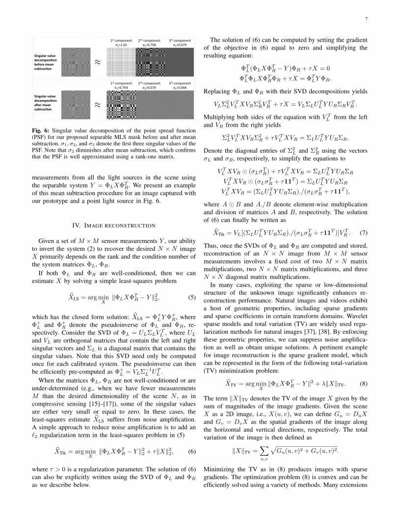
A mask can only modulate light with non-negative trans-mittance values. M-sequences are defined in terms of ±1values and hence cannot be directly implemented in a mask.The masks we use in our prototype cameras are constructedby computing the outer-product of two M-sequences andthen setting the resulting −1 entries to 0. This produces amask that is optically feasible but no longer mathematicallyseparable. We can resolve this issue in post-processing, sincethe difference between the measurements using the theoretical±1 separable mask and the optically feasible 0/1 mask issimply a constant bias term. In practice, once we acquire asensor image, we correct it to correspond to a ±1 separable
(b)!
ΦL
Left system !matrix !!
ΦTR
Horizontal !patterns yield!
Vertical patterns
yield!
Right system !matrix!
(a)!
Separable Hadamard patterns!
!Y = ΦLXΦTRSensor measurements: !
Screen!Separable mask !
on sensor!
Fig. 5: Calibration procedure for measuring the left and right multi-plexing matrices ΦL and ΦR corresponding to a separable mask. (a)Display separable patterns on a screen. The patterns are orthogonal,1D Hadamard codes that are repeated along either the horizontal orvertical direction. (b) Estimated left and right system matrices.
mask (described as Y in (2)) by forcing the column and rowsums to zero, as explained below.
Recall that if we use a separable mask, then we can describesensor measurements as Y = ΦLXΦT
R. If we turn on a singlepixel in X , say Xij = 1, then the sensor measurements wouldbe a rank-1 matrix φiφTj , where φi, φj denote the ith and jthcolumns in ΦL,ΦR, respectively. Let us denote ψ as a 1D M-sequence of length N and Ψ±1 = ψψT as the separable maskthat consists of ±1 entries; it is optically infeasible becausewe cannot subtract light intensities. We created an opticallyfeasible mask by setting all the −1s in Ψ±1 to 0s, which canbe described as
Ψ0/1 = (Ψ±1 + 11T )/2.
Therefore, if we have a single point source in the scene,the sensor image will be a rank-2 matrix. By subtractingthe row and column means of the sensor image, we canconvert the sensor response back to a rank-1 matrix. Only afterthis correction can we represent the superposition of sensor
7
⇡Singular value decomposi2on before mean subtrac2on
1st component σ1=1.65
2nd component σ2=0.704
3rd component σ3=0.079
⇡Singular value decomposi2on a6er mean subtrac2on
1st component σ1=0.704
2nd component σ2=0.079
3rd component σ3=0.044
Fig. 6: Singular value decomposition of the point spread function(PSF) for our proposed separable MLS mask before and after meansubtraction. σ1, σ2, and σ3 denote the first three singular values of thePSF. Note that σ2 diminishes after mean subtraction, which confirmsthat the PSF is well approximated using a rank-one matrix.
measurements from all the light sources in the scene usingthe separable system Y = ΦLXΦT
R. We present an exampleof this mean subtraction procedure for an image captured withour prototype and a point light source in Fig. 6.
IV. IMAGE RECONSTRUCTION
Given a set of M ×M sensor measurements Y , our abilityto invert the system (2) to recover the desired N ×N imageX primarily depends on the rank and the condition number ofthe system matrices ΦL, ΦR.
If both ΦL and ΦR are well-conditioned, then we canestimate X by solving a simple least-squares problem
XLS = arg minX‖ΦLXΦT
R − Y ‖22, (5)
which has the closed form solution: XLS = Φ+LY Φ+
R, whereΦ+
L and Φ+R denote the pseudoinverse of ΦL and ΦR, re-
spectively. Consider the SVD of ΦL = ULΣLVTL , where UL
and VL are orthogonal matrices that contain the left and rightsingular vectors and ΣL is a diagonal matrix that contains thesingular values. Note that this SVD need only be computedonce for each calibrated system. The pseudoinverse can thenbe efficiently pre-computed as Φ+
L = VLΣ−1L UT
L .When the matrices ΦL, ΦR are not well-conditioned or are
under-determined (e.g., when we have fewer measurementsM than the desired dimensionality of the scene N , as incompressive sensing [15]–[17]), some of the singular valuesare either very small or equal to zero. In these cases, theleast-squares estimate XLS suffers from noise amplification.A simple approach to reduce noise amplification is to add an`2 regularization term in the least-squares problem in (5)
XTik = arg minX‖ΦLXΦT
R − Y ‖22 + τ‖X‖22, (6)
where τ > 0 is a regularization parameter. The solution of (6)can also be explicitly written using the SVD of ΦL and ΦR
as we describe below.
The solution of (6) can be computed by setting the gradientof the objective in (6) equal to zero and simplifying theresulting equation:
ΦTL(ΦLXΦT
R − Y )ΦR + τX = 0
ΦTLΦLXΦT
RΦR + τX = ΦTLY ΦR.
Replacing ΦL and ΦR with their SVD decompositions yields
VLΣ2LV
TL XVRΣ2
RVTR + τX = VLΣLU
TL Y URΣRV
TR .
Multiplying both sides of the equation with V TL from the left
and VR from the right yields
Σ2LV
TL XVRΣ2
R + τV TL XVR = ΣLU
TL Y URΣR.
Denote the diagonal entries of Σ2L and Σ2
R using the vectorsσL and σR, respectively, to simplify the equations to
V TL XVR � (σLσ
TR) + τV T
L XVR = ΣLUTL Y URΣR
V TL XVR � (σLσ
TR + τ11T ) = ΣLU
TL Y URΣR
V TL XVR = (ΣLU
TL Y URΣR)./(σLσ
TR + τ11T ),
where A � B and A./B denote element-wise multiplicationand division of matrices A and B, respectively. The solutionof (6) can finally be written as
XTik = VL[(ΣLUTL Y URΣR)./(σLσ
TR + τ11T )]V T
R . (7)
Thus, once the SVDs of ΦL and ΦR are computed and stored,reconstruction of an N × N image from M × M sensormeasurements involves a fixed cost of two M × N matrixmultiplications, two N ×N matrix multiplications, and threeN ×N diagonal matrix multiplications.
In many cases, exploiting the sparse or low-dimensionalstructure of the unknown image significantly enhances re-construction performance. Natural images and videos exhibita host of geometric properties, including sparse gradientsand sparse coefficients in certain transform domains. Waveletsparse models and total variation (TV) are widely used regu-larization methods for natural images [37], [38]. By enforcingthese geometric properties, we can suppress noise amplifica-tion as well as obtain unique solutions. A pertinent examplefor image reconstruction is the sparse gradient model, whichcan be represented in the form of the following total-variation(TV) minimization problem:
XTV = arg minX‖ΦLXΦT
R − Y ‖2 + λ‖X‖TV. (8)
The term ‖X‖TV denotes the TV of the image X given by thesum of magnitudes of the image gradients. Given the sceneX as a 2D image, i.e., X(u, v), we can define Gu = DuXand Gv = DvX as the spatial gradients of the image alongthe horizontal and vertical directions, respectively. The totalvariation of the image is then defined as
‖X‖TV =∑u,v
√Gu(u, v)2 +Gv(u, v)2.
Minimizing the TV as in (8) produces images with sparsegradients. The optimization problem (8) is convex and can beefficiently solved using a variety of methods. Many extensions
8
512x
512 !
Sens
or !
mea
sure
men
ts!
(b)!
Image sensor!B!(a)!Thickness ~ 0.5mm!
Binary mask !on a bare sensor!
Rec
onst
ruct
ed !
imag
es!
(c)!
Fig. 7: Visible FlatCam prototype and results. (a) Prototype consistsof a Sony ICX285 sensor with a separable M-sequence mask placedapproximately 0.5mm from the sensor surface. (b) The sensor mea-surements are different linear combinations of the light from differentpoints in the scene. (c) Reconstructed 512 × 512 color images byprocessing each color channel independently.
and performance analyses are possible following the recentlydeveloped theory of compressive sensing.
In addition to simplifying the calibration task, separabilityof the coded mask also significantly reduces the computationalburden of image reconstruction. Iterative methods for solvingthe optimization problems described above require the re-peated application of the multiplexing matrix and its transpose.Continuing our numerical example from above, for a non-separable, dense mask, both of these operations would requireon the order of 1012 multiplications and additions for mega-pixel images. With a separable mask, however, the applicationof the forward and transpose operators requires only on theorder of 2 × 10⁹ scalar multiplications and additions—atremendous reduction in computational complexity.
V. EXPERIMENTAL RESULTS
We present results on two prototypes. The first uses aSilicon-based sensor to sense in visible wavelengths and thesecond uses an InGaAs sensor for sensing in short-waveinfrared.
A. Visible wavelength FlatCam prototype
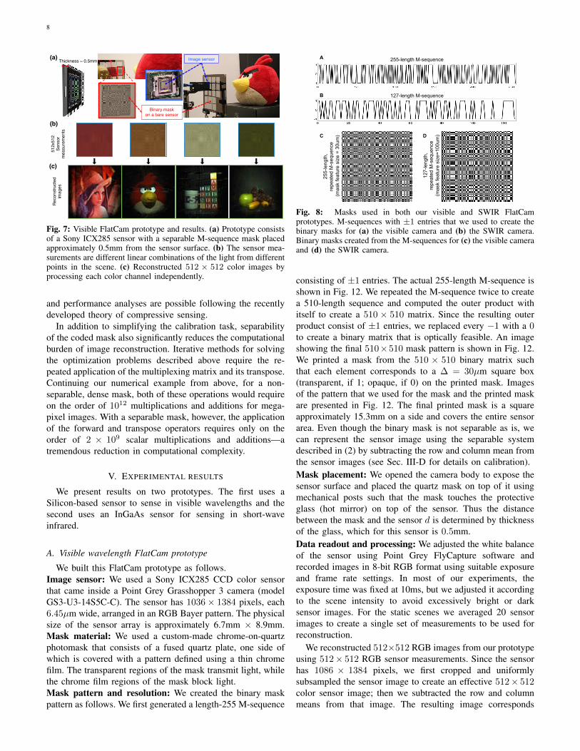
We built this FlatCam prototype as follows.Image sensor: We used a Sony ICX285 CCD color sensorthat came inside a Point Grey Grasshopper 3 camera (modelGS3-U3-14S5C-C). The sensor has 1036× 1384 pixels, each6.45µm wide, arranged in an RGB Bayer pattern. The physicalsize of the sensor array is approximately 6.7mm × 8.9mm.Mask material: We used a custom-made chrome-on-quartzphotomask that consists of a fused quartz plate, one side ofwhich is covered with a pattern defined using a thin chromefilm. The transparent regions of the mask transmit light, whilethe chrome film regions of the mask block light.Mask pattern and resolution: We created the binary maskpattern as follows. We first generated a length-255 M-sequence
255-
leng
th,
repe
ated
M-s
eque
nce
(mas
k fe
atur
e si
ze =
30u
m)
127-length M-sequence
255-length M-sequence
127-
leng
th,
repe
ated
M-s
eque
nce
(mas
k fe
atur
e si
ze=1
00um
)
A
B
C D
Fig. 8: Masks used in both our visible and SWIR FlatCamprototypes. M-sequences with ±1 entries that we used to create thebinary masks for (a) the visible camera and (b) the SWIR camera.Binary masks created from the M-sequences for (c) the visible cameraand (d) the SWIR camera.
consisting of ±1 entries. The actual 255-length M-sequence isshown in Fig. 12. We repeated the M-sequence twice to createa 510-length sequence and computed the outer product withitself to create a 510 × 510 matrix. Since the resulting outerproduct consist of ±1 entries, we replaced every −1 with a 0to create a binary matrix that is optically feasible. An imageshowing the final 510×510 mask pattern is shown in Fig. 12.We printed a mask from the 510 × 510 binary matrix suchthat each element corresponds to a ∆ = 30µm square box(transparent, if 1; opaque, if 0) on the printed mask. Imagesof the pattern that we used for the mask and the printed maskare presented in Fig. 12. The final printed mask is a squareapproximately 15.3mm on a side and covers the entire sensorarea. Even though the binary mask is not separable as is, wecan represent the sensor image using the separable systemdescribed in (2) by subtracting the row and column mean fromthe sensor images (see Sec. III-D for details on calibration).Mask placement: We opened the camera body to expose thesensor surface and placed the quartz mask on top of it usingmechanical posts such that the mask touches the protectiveglass (hot mirror) on top of the sensor. Thus the distancebetween the mask and the sensor d is determined by thicknessof the glass, which for this sensor is 0.5mm.Data readout and processing: We adjusted the white balanceof the sensor using Point Grey FlyCapture software andrecorded images in 8-bit RGB format using suitable exposureand frame rate settings. In most of our experiments, theexposure time was fixed at 10ms, but we adjusted it accordingto the scene intensity to avoid excessively bright or darksensor images. For the static scenes we averaged 20 sensorimages to create a single set of measurements to be used forreconstruction.
We reconstructed 512×512 RGB images from our prototypeusing 512× 512 RGB sensor measurements. Since the sensorhas 1086 × 1384 pixels, we first cropped and uniformlysubsampled the sensor image to create an effective 512× 512color sensor image; then we subtracted the row and columnmeans from that image. The resulting image corresponds
9
(a)!
(b)!
(c)!
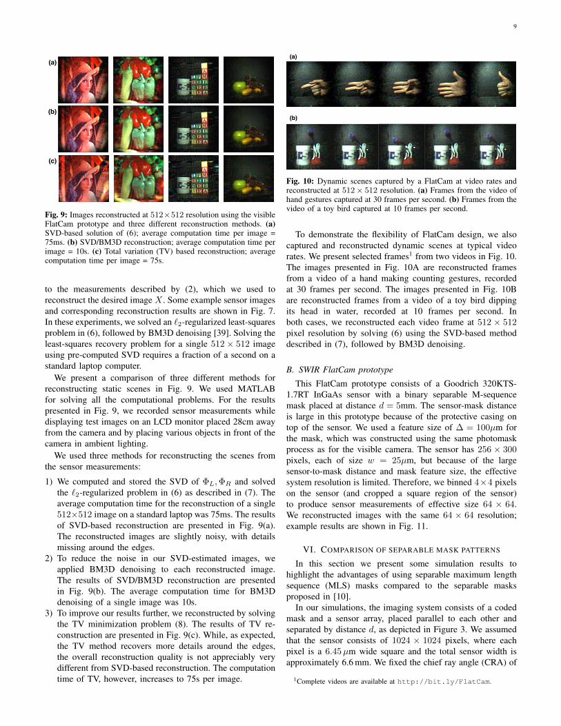
Fig. 9: Images reconstructed at 512×512 resolution using the visibleFlatCam prototype and three different reconstruction methods. (a)SVD-based solution of (6); average computation time per image =75ms. (b) SVD/BM3D reconstruction; average computation time perimage = 10s. (c) Total variation (TV) based reconstruction; averagecomputation time per image = 75s.
to the measurements described by (2), which we used toreconstruct the desired image X . Some example sensor imagesand corresponding reconstruction results are shown in Fig. 7.In these experiments, we solved an `2-regularized least-squaresproblem in (6), followed by BM3D denoising [39]. Solving theleast-squares recovery problem for a single 512× 512 imageusing pre-computed SVD requires a fraction of a second on astandard laptop computer.
We present a comparison of three different methods forreconstructing static scenes in Fig. 9. We used MATLABfor solving all the computational problems. For the resultspresented in Fig. 9, we recorded sensor measurements whiledisplaying test images on an LCD monitor placed 28cm awayfrom the camera and by placing various objects in front of thecamera in ambient lighting.
We used three methods for reconstructing the scenes fromthe sensor measurements:
1) We computed and stored the SVD of ΦL,ΦR and solvedthe `2-regularized problem in (6) as described in (7). Theaverage computation time for the reconstruction of a single512×512 image on a standard laptop was 75ms. The resultsof SVD-based reconstruction are presented in Fig. 9(a).The reconstructed images are slightly noisy, with detailsmissing around the edges.
2) To reduce the noise in our SVD-estimated images, weapplied BM3D denoising to each reconstructed image.The results of SVD/BM3D reconstruction are presentedin Fig. 9(b). The average computation time for BM3Ddenoising of a single image was 10s.
3) To improve our results further, we reconstructed by solvingthe TV minimization problem (8). The results of TV re-construction are presented in Fig. 9(c). While, as expected,the TV method recovers more details around the edges,the overall reconstruction quality is not appreciably verydifferent from SVD-based reconstruction. The computationtime of TV, however, increases to 75s per image.
(a)!
(b)!
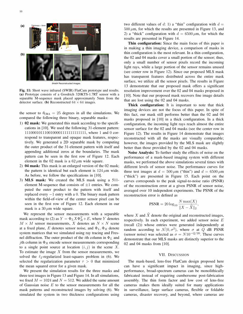
Fig. 10: Dynamic scenes captured by a FlatCam at video rates andreconstructed at 512 × 512 resolution. (a) Frames from the video ofhand gestures captured at 30 frames per second. (b) Frames from thevideo of a toy bird captured at 10 frames per second.
To demonstrate the flexibility of FlatCam design, we alsocaptured and reconstructed dynamic scenes at typical videorates. We present selected frames1 from two videos in Fig. 10.The images presented in Fig. 10A are reconstructed framesfrom a video of a hand making counting gestures, recordedat 30 frames per second. The images presented in Fig. 10Bare reconstructed frames from a video of a toy bird dippingits head in water, recorded at 10 frames per second. Inboth cases, we reconstructed each video frame at 512 × 512pixel resolution by solving (6) using the SVD-based methoddescribed in (7), followed by BM3D denoising.
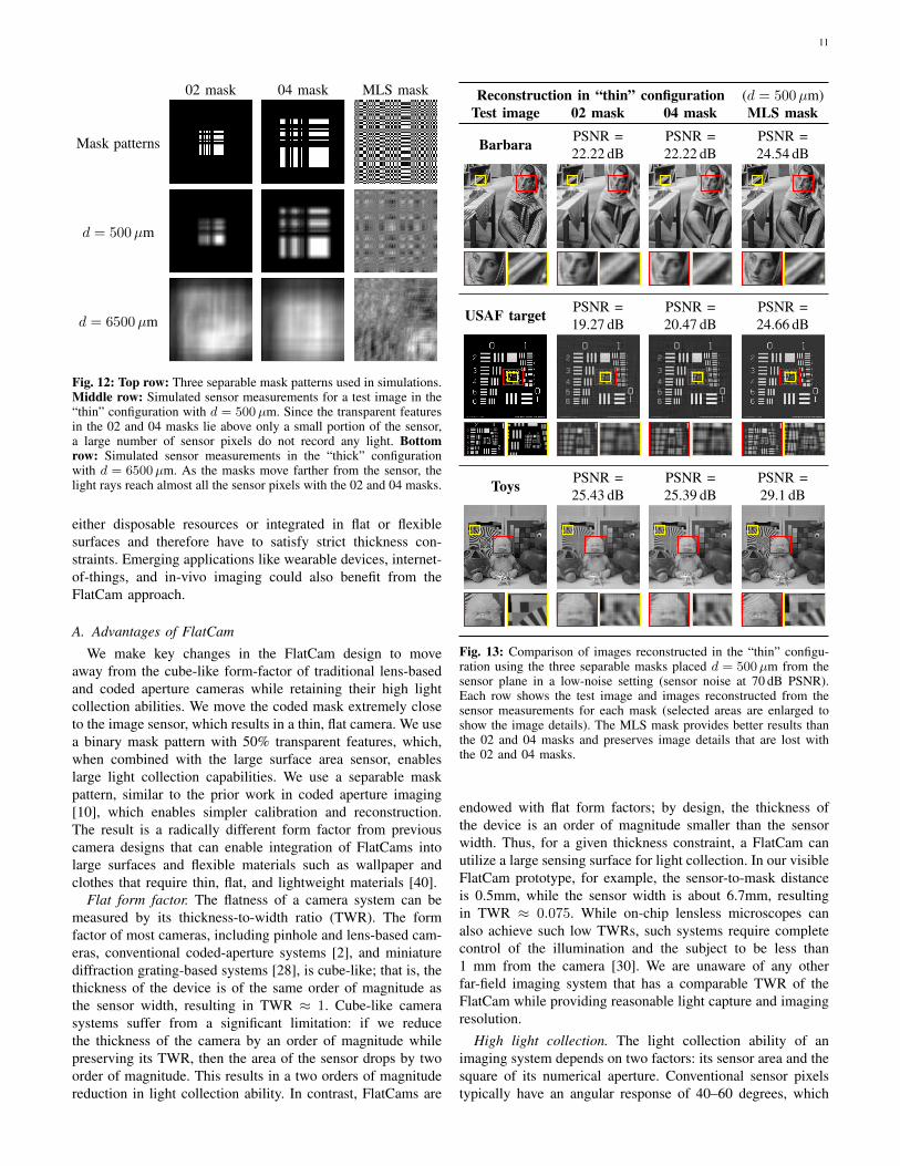
B. SWIR FlatCam prototype
This FlatCam prototype consists of a Goodrich 320KTS-1.7RT InGaAs sensor with a binary separable M-sequencemask placed at distance d = 5mm. The sensor-mask distanceis large in this prototype because of the protective casing ontop of the sensor. We used a feature size of ∆ = 100µm forthe mask, which was constructed using the same photomaskprocess as for the visible camera. The sensor has 256 × 300pixels, each of size w = 25µm, but because of the largesensor-to-mask distance and mask feature size, the effectivesystem resolution is limited. Therefore, we binned 4×4 pixelson the sensor (and cropped a square region of the sensor)to produce sensor measurements of effective size 64 × 64.We reconstructed images with the same 64 × 64 resolution;example results are shown in Fig. 11.
VI. COMPARISON OF SEPARABLE MASK PATTERNS
In this section we present some simulation results tohighlight the advantages of using separable maximum lengthsequence (MLS) masks compared to the separable masksproposed in [10].
In our simulations, the imaging system consists of a codedmask and a sensor array, placed parallel to each other andseparated by distance d, as depicted in Figure 3. We assumedthat the sensor consists of 1024 × 1024 pixels, where eachpixel is a 6.45µm wide square and the total sensor width isapproximately 6.6 mm. We fixed the chief ray angle (CRA) of
1Complete videos are available at http://bit.ly/FlatCam.
10
(a)!
Binary mask!
Image sensor!Thickness ~ 5mm!
(b)!
64x64 Reconstructed images!
Fig. 11: Short wave infrared (SWIR) FlatCam prototype and results.(a) Prototype consists of a Goodrich 320KTS-1.7RT sensor with aseparable M-sequence mask placed approximately 5mm from thedetector surface. (b) Reconstructed 64 × 64 images.
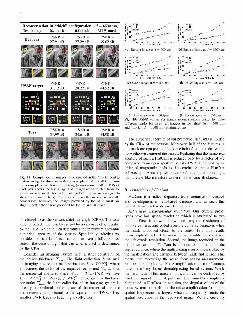
the sensor to θCRA = 25 degrees in all the simulations. Wecompared the following three binary, separable masks:1) 02 mask: We generated this mask according to the specifi-
cations in [10]. We used the following 31-element pattern:1110001011100100001111111111111, where 1 and 0 cor-respond to transparent and opaque mask features, respec-tively. We generated a 2D separable mask by computingthe outer product of the 31-element pattern with itself andappending additional zeros at the boundaries. The maskpattern can be seen in the first row of Figure 12. Eachelement in the 02 mask is a 62µm wide square.
2) 04 mask: This mask is an enlarged version of the 02 mask;the pattern is identical but each element is 124µm wide.As before, we follow the specifications in [10].
3) MLS mask: We created the MLS mask using a 511-element M-sequence that consists of ±1 entries. We com-puted the outer product to the pattern with itself andreplaced every −1 entry with a 0. The binary mask patternwithin the field-of-view of the center sensor pixel can beseen in the first row of Figure 12. Each element in ourmask is a 30µm wide square.
We represent the sensor measurements with a separablemask according to (2) as Y = ΦLXΦT
R +E, where Y denotesM ×M sensor measurements, X denotes an N × N sceneat a fixed plane, E denotes sensor noise, and ΦL,ΦR denotesystem matrices that we simulated using ray tracing and Fres-nel diffraction. The outer product of the ith column in ΦL andjth column in ΦR encode sensor measurements correspondingto a single point source at location (i, j) in the scene X .To estimate the image X from the sensor measurements, wesolved the `2-regularized least-squares problem in (6). Weselected the regularization parameter τ > 0 that minimizedthe mean squared error for a given mask.
We present the simulation results for the three masks andthree test images in Figure 13 and Figure 14. In all simulations,we fixed M = 1024 and N = 512. We added the same amountof Gaussian noise E to the sensor measurements for all themask patterns and reconstructed images by solving (6). Wesimulated the system in two thickness configurations using
two different values of d: 1) a “thin” configuration with d =500µm, for which the results are presented in Figure 13, and2) a “thick” configuration with d = 6500µm, for which theresults are presented in Figure 14.
Thin configuration: Since the main focus of this paper isin making a thin imaging device, a comparison of masks inthin configuration is the most relevant. In a thin configuration,the 02 and 04 masks cover a small portion of the sensor; thus,only a small number of sensor pixels record the incominglight rays, while a large portion of the sensor remains unused(see center row in Figure 12). Since our proposed MLS maskhas transparent features distributed across the entire masksurface, we utilize all the sensor pixels. The results in Figure13 demonstrate that our proposed mask offers a significantresolution improvement over the 02 and 04 masks proposed in[10]. Note that our proposed mask recovers fine image detailsthat are lost using the 02 and 04 masks.
Thick configuration: It is important to note that thickimaging devices are not the focus of this paper. In spite ofthis fact, our mask still performs better than the 02 and 04masks proposed in [10] in a thick configuration. In a thickconfiguration, the incoming light rays reach almost the entiresensor surface for the 02 and 04 masks (see the center row inFigure 12). The results in Figure 14 demonstrate that imagesreconstructed with all the masks are visually comparable;however, the images provided by the MLS mask are slightlybetter than those provided by the 02 and 04 masks.
Noise Analysis: To further study the effects of noise on theperformance of a mask-based imaging system with differentmasks, we performed the above simulations several times withdifferent levels of sensor noise. The performance curves forthree test images at d = 500µm (“thin”) and d = 6500µm(“thick”) are presented in Figure 15. Each point on thecurves corresponds to the peak signal-to-noise ratio (PSNR)of the reconstruction error at a given PSNR of sensor noise,averaged over 10 independent experiments. The PSNR of thereconstruction error is defined as
PSNR = 20 log10
N max(X)
‖X − X‖2,
where X and X denote the original and reconstructed images,respectively. In each experiment, we added sensor noise E(recall (2)) whose entries were generated independently atrandom according to N (0, σ2), where σ at Q dB PSNR(sensor noise) was selected as σ = N10−Q/20. These curvesdemonstrate that our MLS masks are distinctly superior to the02 and 04 masks from [10].
VII. DISCUSSION
The mask-based, lens-free FlatCam design proposed herecan have a significant impact in imaging, since high-performance, broad-spectrum cameras can be monolithicallyfabricated instead of requiring cumbersome post-fabricationassembly. The thin form factor and low cost of lens-freecameras makes them ideally suited for many applicationsin surveillance, large surface cameras, flexible or foldablecameras, disaster recovery, and beyond, where cameras are
11
02 mask 04 mask MLS mask
Mask patterns
d = 500µm
d = 6500µm
Fig. 12: Top row: Three separable mask patterns used in simulations.Middle row: Simulated sensor measurements for a test image in the“thin” configuration with d = 500µm. Since the transparent featuresin the 02 and 04 masks lie above only a small portion of the sensor,a large number of sensor pixels do not record any light. Bottomrow: Simulated sensor measurements in the “thick” configurationwith d = 6500µm. As the masks move farther from the sensor, thelight rays reach almost all the sensor pixels with the 02 and 04 masks.
either disposable resources or integrated in flat or flexiblesurfaces and therefore have to satisfy strict thickness con-straints. Emerging applications like wearable devices, internet-of-things, and in-vivo imaging could also benefit from theFlatCam approach.
A. Advantages of FlatCam
We make key changes in the FlatCam design to moveaway from the cube-like form-factor of traditional lens-basedand coded aperture cameras while retaining their high lightcollection abilities. We move the coded mask extremely closeto the image sensor, which results in a thin, flat camera. We usea binary mask pattern with 50% transparent features, which,when combined with the large surface area sensor, enableslarge light collection capabilities. We use a separable maskpattern, similar to the prior work in coded aperture imaging[10], which enables simpler calibration and reconstruction.The result is a radically different form factor from previouscamera designs that can enable integration of FlatCams intolarge surfaces and flexible materials such as wallpaper andclothes that require thin, flat, and lightweight materials [40].
Flat form factor. The flatness of a camera system can bemeasured by its thickness-to-width ratio (TWR). The formfactor of most cameras, including pinhole and lens-based cam-eras, conventional coded-aperture systems [2], and miniaturediffraction grating-based systems [28], is cube-like; that is, thethickness of the device is of the same order of magnitude asthe sensor width, resulting in TWR ≈ 1. Cube-like camerasystems suffer from a significant limitation: if we reducethe thickness of the camera by an order of magnitude whilepreserving its TWR, then the area of the sensor drops by twoorder of magnitude. This results in a two orders of magnitudereduction in light collection ability. In contrast, FlatCams are
Reconstruction in “thin” configuration (d = 500µm)Test image 02 mask 04 mask MLS mask
Barbara PSNR =22.22 dB
PSNR =22.22 dB
PSNR =24.54 dB
USAF target PSNR =19.27 dB
PSNR =20.47 dB
PSNR =24.66 dB
Toys PSNR =25.43 dB
PSNR =25.39 dB
PSNR =29.1 dB
Fig. 13: Comparison of images reconstructed in the “thin” configu-ration using the three separable masks placed d = 500µm from thesensor plane in a low-noise setting (sensor noise at 70 dB PSNR).Each row shows the test image and images reconstructed from thesensor measurements for each mask (selected areas are enlarged toshow the image details). The MLS mask provides better results thanthe 02 and 04 masks and preserves image details that are lost withthe 02 and 04 masks.
endowed with flat form factors; by design, the thickness ofthe device is an order of magnitude smaller than the sensorwidth. Thus, for a given thickness constraint, a FlatCam canutilize a large sensing surface for light collection. In our visibleFlatCam prototype, for example, the sensor-to-mask distanceis 0.5mm, while the sensor width is about 6.7mm, resultingin TWR ≈ 0.075. While on-chip lensless microscopes canalso achieve such low TWRs, such systems require completecontrol of the illumination and the subject to be less than1 mm from the camera [30]. We are unaware of any otherfar-field imaging system that has a comparable TWR of theFlatCam while providing reasonable light capture and imagingresolution.
High light collection. The light collection ability of animaging system depends on two factors: its sensor area and thesquare of its numerical aperture. Conventional sensor pixelstypically have an angular response of 40–60 degrees, which
12
Reconstruction in “thick” configuration (d = 6500µm)Test image 02 mask 04 mask MLS mask
Barbara PSNR =27.91 dB
PSNR =27.29 dB
PSNR =39.02 dB
USAF target PSNR =31.12 dB
PSNR =28.22 dB
PSNR =44.52 dB
Toys PSNR =34.99 dB
PSNR =34.61 dB
PSNR =44.98 dB
Fig. 14: Comparison of images reconstructed in the “thick” config-uration using the three separable masks placed d = 6500µm fromthe sensor plane in a low-noise setting (sensor noise at 70 dB PSNR).Each row shows the test image and images reconstructed from thesensor measurements for each mask (selected areas are enlarged toshow the image details). The results for all the masks are visuallycomparable; however, the images provided by the MLS mask areslightly better than those provided by the 02 and 04 masks.
is referred to as the sensors chief ray angle (CRA). The totalamount of light that can be sensed by a sensor is often limitedby the CRA, which in turn determines the maximum allowablenumerical aperture of the system. Specifically, whether weconsider the best lens-based camera, or even a fully exposedsensor, the cone of light that can enter a pixel is determinedby the CRA.
Consider an imaging system with a strict constraint onthe device thickness Tmax. The light collection L of suchan imaging device can be described as L ∝ W 2N2
A, whereW denotes the width of the (square) sensor and NA denotesthe numerical aperture. Since Wmax = Tmax/TWR, we haveL ∝ W 2N2
A ≤ (NATmax/TWR)2. Thus, given a thicknessconstraint Tmax, the light collection of an imaging system isdirectly proportional to the square of the numerical apertureand inversely proportional to the square of its TWR. Thus,smaller TWR leads to better light collection.
(a) Barbara image at d = 500µm (b) Barbara image at d = 6500µm
(c) USAF target at d = 500µm (d) USAF target at d = 6500µm
(e) Toys image at d = 500µm (f) Toys image at d = 6500µmFig. 15: PSNR curves for image reconstructions using the threedifferent masks for three test images in the “thin” (d = 500µm)and “thick” (d = 6500µm) configurations.
The numerical aperture of our prototype FlatCams is limitedby the CRA of the sensors. Moreover, half of the features inour mask are opaque and block one half of the light that wouldhave otherwise entered the sensor. Realizing that the numericalaperture of such a FlatCam is reduced only by a factor of
√2
compared to an open aperture, yet its TWR is reduced by anorder of magnitude leads to the conclusion that a FlatCamcollects approximately two orders of magnitude more lightthan a cube-like miniature camera of the same thickness.
B. Limitations of FlatCam
FlatCam is a radical departure from centuries of researchand development in lens-based cameras, and as such thisradical departure has its own limitations.
Achievable image/angular resolution. Our current proto-types have low spatial resolution which is attributed to twofactors. First, it is well known that angular resolution ofpinhole cameras and coded aperture cameras decreases whenthe mask is moved closer to the sensor [7]. This resultsin an implicit tradeoff between the achievable thickness andthe achievable resolution. Second, the image recorded on theimage sensor in a FlatCam is a linear combination of thescene radiance, where the multiplexing matrix is controlled bythe mask pattern and distance between mask and sensor. Thismeans that recovering the scene from sensor measurementsrequires demultiplexing. Noise amplification is an unfortunateoutcome of any linear demultiplexing based system. Whilethe magnitude of this noise amplification can be controlled bycareful design of the mask patterns, they cannot be completelyeliminated in FlatCam. In addition, the singular values of thelinear system are such that the noise amplification for higherspatial frequencies is larger, which consequently limits thespatial resolution of the recovered image. We are currently
13
working on several techniques to improve the spatial resolutionof the recovered images.
Direct-view and real-time operation. In traditional lens-based cameras, the image sensed by the image sensor isthe photograph of the scene. In FlatCam, a computationalalgorithm is required to convert the sensor measurementsinto a photograph of the scene. This results in a time-lagbetween the sensor acquisition and the image display, a time-lag that depends on processing time. Currently, our SVD-based reconstruction operates at near real-time (about 10 fps)resulting in about a 100 ms delay between capture and display.While this may be acceptable for certain applications, thereare many other applications such as augmented reality andvirtual reality, where such delays are unacceptable. Orderof magnitude improvements in processing times are requiredbefore FlatCam becomes amenable to such applications.
ACKNOWLEDGMENTS
This work was partially supported by NSF grantsCCF1117939, CCF1527501, CCF-1502875, DARPA RE-VEAL grant HR0011-16-C-0028, ONR DURIP grant N00014-15-1-2878, ONR grant N00014-15-1-2735 and ARO MURIW911NF0910383. The bio portraits of SA, AA and AS weresimulated with FlatCam, while those for AV and RB weretaken with FlatCam prototype.
REFERENCES
[1] R. Dicke, “Scatter-hole cameras for x-rays and gamma rays,” TheAstrophysical Journal, vol. 153, p. L101, 1968.
[2] E. Fenimore and T. Cannon, “Coded aperture imaging with uniformlyredundant arrays,” Applied optics, vol. 17, no. 3, pp. 337–347, 1978.
[3] S. R. Gottesman and E. Fenimore, “New family of binary arrays forcoded aperture imaging,” Applied optics, vol. 28, no. 20, pp. 4344–4352,1989.
[4] T. Cannon and E. Fenimore, “Coded aperture imaging: Many holes makelight work,” Optical Engineering, vol. 19, no. 3, pp. 193–283, 1980.
[5] P. Durrant, M. Dallimore, I. Jupp, and D. Ramsden, “The applicationof pinhole and coded aperture imaging in the nuclear environment,”Nuclear Instruments and Methods in Physics Research Section A:Accelerators, Spectrometers, Detectors and Associated Equipment, vol.422, no. 1, pp. 667–671, 1999.
[6] V. Dragoi, A. Filbert, S. Zhu, and G. Mittendorfer, “Cmos wafer bondingfor back-side illuminated image sensors fabrication,” in 2010 11thInternational Conference on Electronic Packaging Technology & HighDensity Packaging, 2010, pp. 27–30.
[7] D. J. Brady, Optical imaging and spectroscopy. John Wiley & Sons,2009.
[8] A. Zomet and S. K. Nayar, “Lensless imaging with a controllableaperture,” in IEEE Computer Society Conference on Computer Visionand Pattern Recognition, vol. 1, 2006, pp. 339–346.
[9] G. Huang, H. Jiang, K. Matthews, and P. Wilford, “Lensless imaging bycompressive sensing,” in 20th IEEE International Conference on ImageProcessing, 2013, pp. 2101–2105.
[10] M. J. DeWeert and B. P. Farm, “Lensless coded-aperture imaging withseparable doubly-Toeplitz masks,” Optical Engineering, vol. 54, no. 2,pp. 023 102–023 102, 2015.
[11] A. Levin, R. Fergus, F. Durand, and W. T. Freeman, “Image and depthfrom a conventional camera with a coded aperture,” in ACM Transactionson Graphics (TOG), vol. 26, no. 3. ACM, 2007, p. 70.
[12] D. Liu, J. Gu, Y. Hitomi, M. Gupta, T. Mitsunaga, and S. Nayar,“Efficient Space-Time Sampling with Pixel-wise Coded Exposure forHigh Speed Imaging,” IEEE Transactions on Pattern Analysis andMachine Intelligence, vol. 99, p. 1, 2013.
[13] A. Veeraraghavan, R. Raskar, A. Agrawal, A. Mohan, and J. Tumblin,“Dappled photography: Mask enhanced cameras for heterodyned lightfields and coded aperture refocusing,” ACM Transactions on Graphics(TOG), vol. 26, no. 3, p. 69, 2007.
[14] K. Marwah, G. Wetzstein, Y. Bando, and R. Raskar, “Compressivelight field photography using overcomplete dictionaries and optimizedprojections,” ACM Transactions on Graphics (TOG), vol. 32, no. 4, p. 46,2013.
[15] E. J. Candes, J. K. Romberg, and T. Tao, “Stable signal recovery fromincomplete and inaccurate measurements,” Communications on pure andapplied mathematics, vol. 59, no. 8, pp. 1207–1223, 2006.
[16] D. L. Donoho, “Compressed sensing,” IEEE Transactions on Informa-tion Theory, vol. 52, no. 4, pp. 1289–1306, 2006.
[17] R. G. Baraniuk, “Compressive sensing,” IEEE signal processing maga-zine, vol. 24, no. 4, 2007.
[18] R. F. Marcia and R. M. Willett, “Compressive coded aperture super-resolution image reconstruction,” in IEEE International Conference onAcoustics, Speech and Signal Processing (ICASSP), 2008, pp. 833–836.
[19] A. Wagadarikar, R. John, R. Willett, and D. Brady, “Single disperserdesign for coded aperture snapshot spectral imaging,” Applied optics,vol. 47, no. 10, pp. B44–B51, 2008.
[20] P. Llull, X. Liao, X. Yuan, J. Yang, D. Kittle, L. Carin, G. Sapiro, andD. J. Brady, “Coded aperture compressive temporal imaging,” Opticsexpress, vol. 21, no. 9, pp. 10 526–10 545, 2013.
[21] J. Tanida, T. Kumagai, K. Yamada, S. Miyatake, K. Ishida, T. Morimoto,N. Kondou, D. Miyazaki, and Y. Ichioka, “Thin observation module bybound optics (TOMBO): concept and experimental verification,” Appliedoptics, vol. 40, no. 11, pp. 1806–1813, 2001.
[22] M. Shankar, R. Willett, N. Pitsianis, T. Schulz, R. Gibbons, R. Te Kolste,J. Carriere, C. Chen, D. Prather, and D. Brady, “Thin infrared imagingsystems through multichannel sampling,” Applied optics, vol. 47, no. 10,pp. B1–B10, 2008.
[23] A. Bruckner, J. Duparre, R. Leitel, P. Dannberg, A. Brauer, andA. Tunnermann, “Thin wafer-level camera lenses inspired by insectcompound eyes,” Optics Express, vol. 18, no. 24, pp. 24 379–24 394,2010.
[24] K. Venkataraman, D. Lelescu, J. Duparre, A. McMahon, G. Molina,P. Chatterjee, R. Mullis, and S. Nayar, “Picam: An ultra-thin highperformance monolithic camera array,” ACM Transactions on Graphics(TOG), vol. 32, no. 6, p. 166, 2013.
[25] E. J. Tremblay, R. A. Stack, R. L. Morrison, and J. E. Ford, “Ultrathincameras using annular folded optics,” Applied optics, vol. 46, no. 4, pp.463–471, 2007.
[26] A. Wang, P. Gill, and A. Molnar, “Angle sensitive pixels in cmos forlensless 3d imaging,” in IEEE Custom Integrated Circuits Conference,2009, pp. 371–374.
[27] P. R. Gill, C. Lee, D.-G. Lee, A. Wang, and A. Molnar, “A mi-croscale camera using direct fourier-domain scene capture,” Opticsletters, vol. 36, no. 15, pp. 2949–2951, 2011.
[28] P. R. Gill and D. G. Stork, “Lensless ultra-miniature imagers using odd-symmetry spiral phase gratings,” in Computational Optical Sensing andImaging. Optical Society of America, 2013, pp. CW4C–3.
[29] D. Stork and P. Gill, “Lensless ultra-miniature cmos computational im-agers and sensors,” in International Conference on Sensor Technologiesand Applications, 2013, pp. 186–190.
[30] A. Greenbaum, W. Luo, T.-W. Su, Z. Gorocs, L. Xue, S. O. Isik-man, A. F. Coskun, O. Mudanyali, and A. Ozcan, “Imaging withoutlenses: Achievements and remaining challenges of wide-field on-chipmicroscopy,” Nature methods, vol. 9, no. 9, pp. 889–895, 2012.
[31] A. Greenbaum, Y. Zhang, A. Feizi, P.-L. Chung, W. Luo, S. R.Kandukuri, and A. Ozcan, “Wide-field computational imaging of pathol-ogy slides using lens-free on-chip microscopy,” Science translationalmedicine, vol. 6, no. 267, pp. 267ra175–267ra175, 2014.
[32] F. J. MacWilliams and N. J. Sloane, “Pseudo-random sequences andarrays,” Proceedings of the IEEE, vol. 64, no. 12, pp. 1715–1729, 1976.
[33] A. Busboom, H. Elders-Boll, and H. Schotten, “Uniformly redundantarrays,” Experimental Astronomy, vol. 8, no. 2, pp. 97–123, 1998.
[34] S. W. Golomb, Shift register sequences. Aegean Park Press, 1982.[35] E. Fenimore and G. Weston, “Fast delta hadamard transform,” Applied
optics, vol. 20, no. 17, pp. 3058–3067, 1981.[36] J. Ding, M. Noshad, and V. Tarokh, “Complementary lattice arrays for
coded aperture imaging,” arXiv preprint arXiv:1506.02160, 2015.[37] S. Mallat, A wavelet tour of signal processing: the sparse way. Aca-
demic press, 2008.[38] L. I. Rudin, S. Osher, and E. Fatemi, “Nonlinear total variation based
noise removal algorithms,” Physica D: Nonlinear Phenomena, vol. 60,no. 1, pp. 259–268, 1992.
[39] K. Dabov, A. Foi, V. Katkovnik, and K. Egiazarian, “Image denoising bysparse 3-d transform-domain collaborative filtering,” IEEE Transactionson Image Processing, vol. 16, no. 8, pp. 2080–2095, 2007.
14
[40] F. Koppens, T. Mueller, P. Avouris, A. Ferrari, M. Vitiello, and M. Polini,“Photodetectors based on graphene, other two-dimensional materials andhybrid systems,” Nature nanotechnology, vol. 9, no. 10, pp. 780–793,2014.
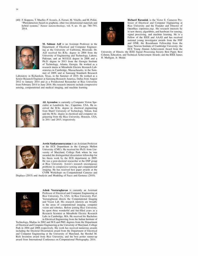
M. Salman Asif is an Assistant Professor in theDepartment of Electrical and Computer Engineer-ing at the University of California, Riverside. Dr.Asif received his B.Sc. degree in 2004 from theUniversity of Engineering and Technology, Lahore,Pakistan, and an M.S.E.E degree in 2008 and aPh.D. degree in 2013 from the Georgia Instituteof Technology, Atlanta, Georgia. He worked as aresearch intern at Mitsubishi Electric Research Lab-oratories in Cambridge, Massachusetts, in the Sum-mer of 2009, and at Samsung Standards Research
Laboratory in Richardson, Texas, in the Summer of 2010. He worked as aSenior Research Engineer at Samsung Research America, Dallas from August2012 to January 2014 and as a Postdoctoral Researcher at Rice Universityfrom February 2014 to June 2016. His research interests include compressivesensing, computational and medical imaging, and machine learning.
Ali Ayremlou is currently a Computer Vision Spe-cialist at Lensbricks Inc., Cupertino, USA. He re-ceived the B.Sc. degree in electrical engineeringfrom Sharif University of Technology, Tehran, Iranand the M.Sc. degree in electrical and computer en-gineering from the Rice University, Houston, USA,in 2011 and 2015, respectively.
Aswin Sankaranarayanan is an Assistant Professorat the ECE Department in the Carnegie MellonUniversity (CMU). He received his Ph.D. from Uni-versity of Maryland, College Park where he wasawarded the distinguished dissertation fellowship forhis thesis work by the ECE department in 2009.He was a post-doctoral researcher at the DSP groupat Rice University. Aswin’s research encompassesproblems in compressive sensing and computationalimaging. He has received best paper awards at theCVPR Workshops on Computational Cameras and
Displays (2015) and Analysis and Modeling of Faces and Gestures (2010).
Ashok Veeraraghavan is currently an AssistantProfessor of Electrical and Computer Engineering atRice University, Tx, USA. At Rice University, Prof.Veeraraghavan directs the Computational Imagingand Vision Lab. His research interests are broadlyin the areas of computational imaging, computervision and robotics. Before joining Rice University,he spent three wonderful and fun-filled years as aResearch Scientist at Mitsubishi Electric ResearchLabs in Cambridge, MA. He received his Bachelorsin Electrical Engineering from the Indian Institute of
Technology, Madras in 2002 and M.S and PhD. degrees from the Departmentof Electrical and Computer Engineering at the University of Maryland, CollegePark in 2004 and 2008 respectively. His work has received numerous awardsincluding the Doctoral Dissertation award from the Department of Electricaland Computer Engineering at the University of Maryland, the Hershel M.Rich Invention award from Rice University, and the best poster runner-upaward from International Conference on Computational Photography, 2014.
Richard Baraniuk is the Victor E. Cameron Pro-fessor of Electrical and Computer Engineering atRice University and the Founder and Director ofOpenStax (openstax.org). His research interests liein new theory, algorithms, and hardware for sensing,signal processing, and machine learning. He is aFellow of the IEEE and AAAS and has receivednational young investigator awards from the NSFand ONR; the Rosenbaum Fellowship from theIsaac Newton Institute of Cambridge University; theECE Young Alumni Achievement Award from the
University of Illinois; the IEEE Signal Processing Society Best Paper, BestColumn, Education, and Technical Achievement Awards; and the IEEE JamesH. Mulligan, Jr. Medal.