Lecture 4: The VHDL N-bit adderosorio.wait4.org/SSC0113/AULA02/eecs_317_adder.pdfCWRU EECS 317 EECS...
26
CWRU EECS 317 EECS 317 Computer Design LECTURE 4: The VHDL N-bit Adder Instructor: Francis G. Wolff [email protected] Case Western Reserve University
Transcript of Lecture 4: The VHDL N-bit adderosorio.wait4.org/SSC0113/AULA02/eecs_317_adder.pdfCWRU EECS 317 EECS...
CWRU EECS 317
EECS 317
Computer Design
LECTURE 4:
The VHDL N-bit Adder
Instructor: Francis G. Wolff
Case Western Reserve University
CWRU EECS 317
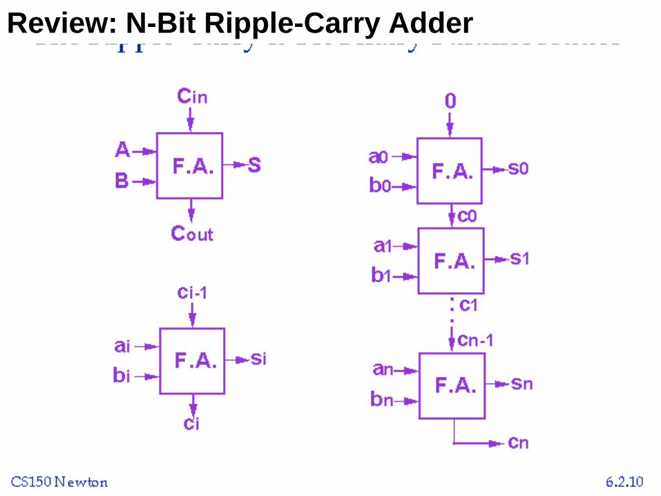
Review: N-Bit Ripple-Carry Adder

CWRU EECS 317
Hierarchical design: 2-bit adder
LIBRARY IEEE;
USE IEEE.std_logic_1164.ALL;
ENTITY adder_bits_2 IS
PORT (Cin: IN std_logic;
a0, b0, a1, b1: IN std_logic;
S0, S1: OUT std_logic;
Cout: OUT std_logic
); END;
• The design interface to a two bit adder is
• Note: that the ports are positional dependant
(Cin, a0, b0, a1, b1, S0, S1, Cout)
CWRU EECS 317
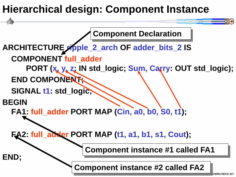
Hierarchical design: Component Instance
ARCHITECTURE ripple_2_arch OF adder_bits_2 IS
COMPONENT full_adder
PORT (x, y, z: IN std_logic; Sum, Carry: OUT std_logic);
END COMPONENT;
SIGNAL t1: std_logic;
BEGIN
FA1: full_adder PORT MAP (Cin, a0, b0, S0, t1);
FA2: full_adder PORT MAP (t1, a1, b1, s1, Cout);
END; Component instance #1 called FA1
Component instance #2 called FA2
Component Declaration
CWRU EECS 317
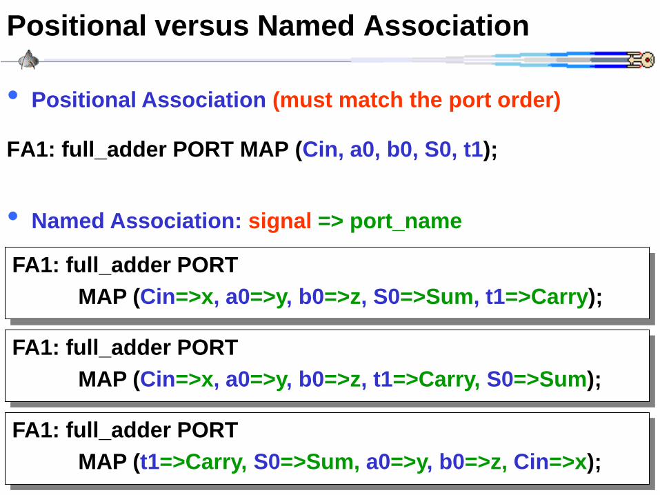
Positional versus Named Association
FA1: full_adder PORT MAP (Cin, a0, b0, S0, t1);
FA1: full_adder PORT
MAP (Cin=>x, a0=>y, b0=>z, S0=>Sum, t1=>Carry);
• Positional Association (must match the port order)
• Named Association: signal => port_name
FA1: full_adder PORT
MAP (Cin=>x, a0=>y, b0=>z, t1=>Carry, S0=>Sum);
FA1: full_adder PORT
MAP (t1=>Carry, S0=>Sum, a0=>y, b0=>z, Cin=>x);

CWRU EECS 317
Component by Named Association
ARCHITECTURE ripple_2_arch OF adder_bits_2 IS
COMPONENT full_adder
PORT (x, y, z: IN std_logic; Sum, Carry: OUT std_logic);
END COMPONENT;
SIGNAL t1: std_logic; -- Temporary carry signal
BEGIN
-- Named association
FA1: full_adder PORT
MAP (Cin=>x, a0=>y, b0=>z, S0=>Sum, t1=>Carry);
-- Positional association
FA2: full_adder PORT MAP (t1, a1, b1, s1, Cout);
END; -- Comments start with a double dash
CWRU EECS 317
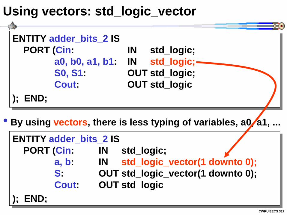
Using vectors: std_logic_vector
ENTITY adder_bits_2 IS
PORT (Cin: IN std_logic;
a0, b0, a1, b1: IN std_logic;
S0, S1: OUT std_logic;
Cout: OUT std_logic
); END;
• By using vectors, there is less typing of variables, a0, a1, ...
ENTITY adder_bits_2 IS
PORT (Cin: IN std_logic;
a, b: IN std_logic_vector(1 downto 0);
S: OUT std_logic_vector(1 downto 0);
Cout: OUT std_logic
); END;
CWRU EECS 317
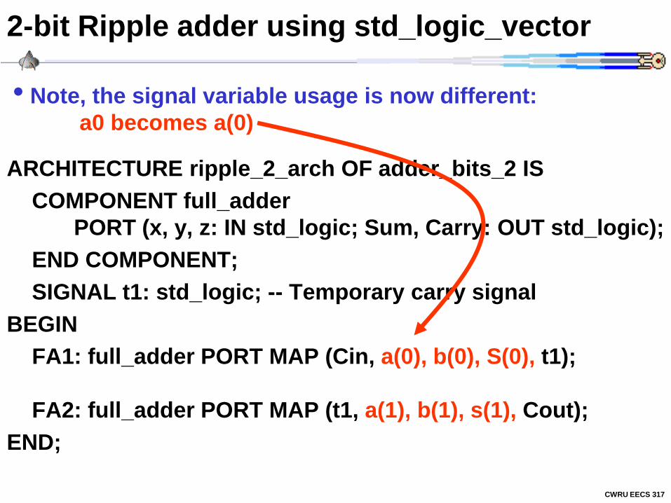
2-bit Ripple adder using std_logic_vector
ARCHITECTURE ripple_2_arch OF adder_bits_2 IS
COMPONENT full_adder
PORT (x, y, z: IN std_logic; Sum, Carry: OUT std_logic);
END COMPONENT;
SIGNAL t1: std_logic; -- Temporary carry signal
BEGIN
FA1: full_adder PORT MAP (Cin, a(0), b(0), S(0), t1);
FA2: full_adder PORT MAP (t1, a(1), b(1), s(1), Cout);
END;
• Note, the signal variable usage is now different:
a0 becomes a(0)

CWRU EECS 317
4-bit Ripple adder using std_logic_vector
ARCHITECTURE ripple_4_arch OF adder_bits_4 IS
COMPONENT full_adder
PORT (x, y, z: IN std_logic; Sum, Carry: OUT std_logic);
END COMPONENT;
SIGNAL t: std_logic_vector(3 downto 1);
BEGIN
FA1: full_adder PORT MAP (Cin, a(0), b(0), S(0), t(1));
FA2: full_adder PORT MAP (t(1), a(1), b(1), S(1), t(2));
FA3: full_adder PORT MAP (t(2), a(2), b(2), S(2), t(3));
FA4: full_adder PORT MAP (t(3), a(3), b(3), S(3), Cout);
END;
• std_vectors make it easier to replicate structures
CWRU EECS 317
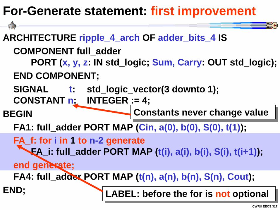
For-Generate statement: first improvement
ARCHITECTURE ripple_4_arch OF adder_bits_4 IS
COMPONENT full_adder
PORT (x, y, z: IN std_logic; Sum, Carry: OUT std_logic);
END COMPONENT;
SIGNAL t: std_logic_vector(3 downto 1);
CONSTANT n: INTEGER := 4;
BEGIN
FA1: full_adder PORT MAP (Cin, a(0), b(0), S(0), t(1));
FA2: full_adder PORT MAP (t(1), a(1), b(1), S(1), t(2));
FA3: full_adder PORT MAP (t(2), a(2), b(2), S(2), t(3));
FA4: full_adder PORT MAP (t(n), a(n), b(n), S(n), Cout);
END;
Constants never change value
FA_f: for i in 1 to n-2 generate
FA_i: full_adder PORT MAP (t(i), a(i), b(i), S(i), t(i+1));
end generate;
LABEL: before the for is not optional

CWRU EECS 317
For-Generate statement: second improvement
ARCHITECTURE ripple_4_arch OF adder_bits_4 IS
COMPONENT full_adder
PORT (x, y, z: IN std_logic; Sum, Carry: OUT std_logic);
END COMPONENT;
SIGNAL t: std_logic_vector(4 downto 0);
CONSTANT n: INTEGER := 4;
BEGIN
t(0) <= Cin; Cout <= t(n);
FA_f: for i in 0 to n-1 generate
FA_i: full_adder PORT MAP (t(i), a(i), b(i), S(i), t(i+1));
end generate;
END;
Keep track of vector sizes

CWRU EECS 317
N-bit adder using generic
• By using generics, the design can be generalized
ENTITY adder_bits_4 IS
PORT (Cin: IN std_logic;
a, b: IN std_logic_vector(3 downto 0);
S: OUT std_logic_vector(3 downto 0);
Cout: OUT std_logic
); END;
ENTITY adder_bits_n IS
PORT (Cin: IN std_logic;
a, b: IN std_logic_vector(n-1 downto 0);
S: OUT std_logic_vector(n-1 downto 0);
Cout: OUT std_logic
); END;
GENERIC(n: INTEGER := 2);
Default case is 2
a, b: IN std_logic_vector(n-1 downto 0);
S: OUT std_logic_vector(n-1 downto 0);
CWRU EECS 317
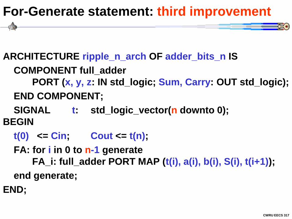
For-Generate statement: third improvement
ARCHITECTURE ripple_n_arch OF adder_bits_n IS
COMPONENT full_adder
PORT (x, y, z: IN std_logic; Sum, Carry: OUT std_logic);
END COMPONENT;
SIGNAL t: std_logic_vector(n downto 0);
BEGIN
t(0) <= Cin; Cout <= t(n);
FA: for i in 0 to n-1 generate
FA_i: full_adder PORT MAP (t(i), a(i), b(i), S(i), t(i+1));
end generate;
END;

CWRU EECS 317
Stimulus Only Test Bench Architecture
ARCHITECTURE adder_bits_4_tb_arch OF adder_bits_4_tb IS
COMPONENT adder_bits_n
GENERIC(n: INTEGER := 2);
PORT ( Cin: IN std_logic;
a, b: IN std_logic_vector(n-1 downto 0);
S: OUT std_logic_vector(n-1 downto 0);
Cout: OUT std_logic
END COMPONENT;
SIGNAL x, y, Sum: std_logic_vector(n downto 0);
SIGNAL c, Cout: std_logic;
BEGIN
x <= “0000”, “0001” after 50 ns, “0101”, after 100 ns;
y <= “0010”, “0011” after 50 ns, “1010”, after 100 ns;
c <= ‘1’, ‘0’ after 50 ns;
UUT_ADDER_4: adder_bits_n GENERIC MAP(4)
PORT MAP (c, x, y, Sum, Cout);
END;
MAP(4)
Overrides
default 2
CWRU EECS 317
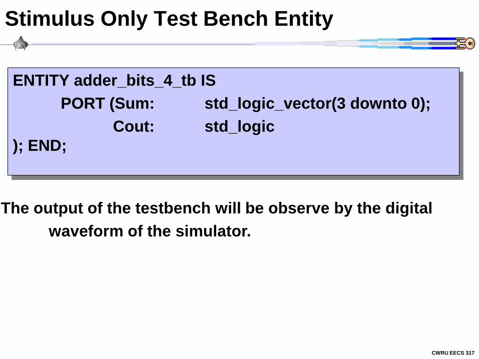
Stimulus Only Test Bench Entity
ENTITY adder_bits_4_tb IS
PORT (Sum: std_logic_vector(3 downto 0);
Cout: std_logic
); END;
The output of the testbench will be observe by the digital
waveform of the simulator.
CWRU EECS 317
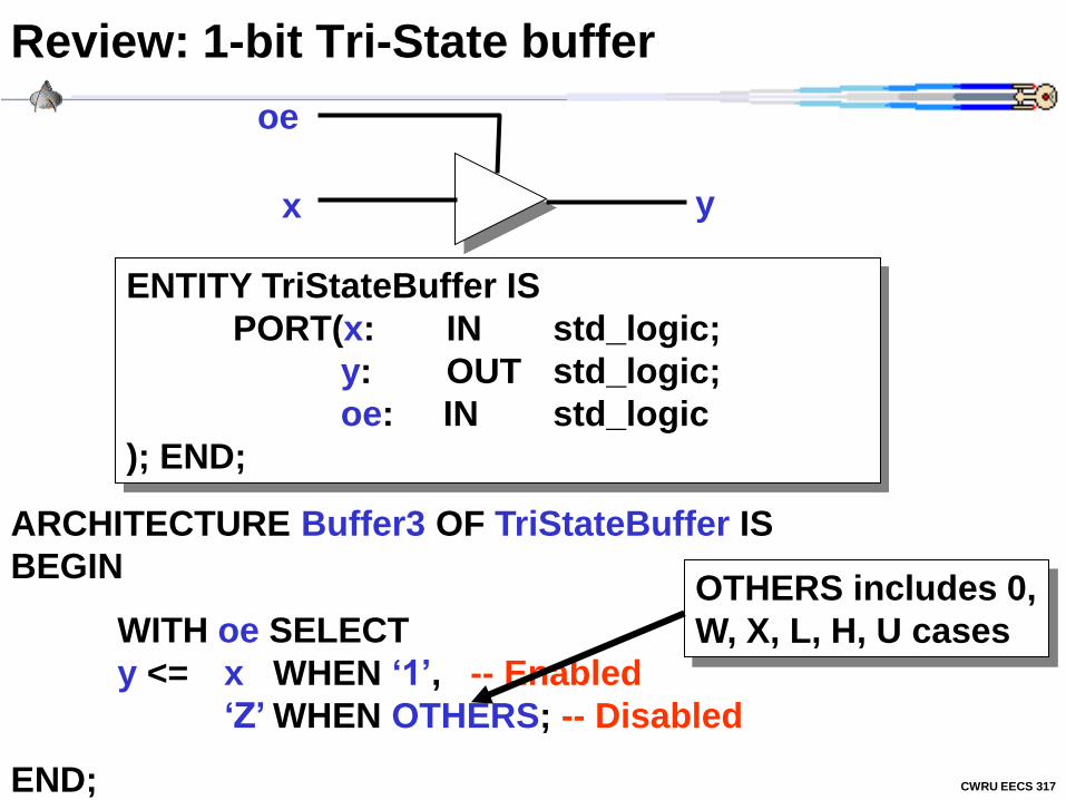
Review: 1-bit Tri-State buffer
oe
y x
ENTITY TriStateBuffer IS
PORT(x: IN std_logic;
y: OUT std_logic;
oe: IN std_logic
); END;
ARCHITECTURE Buffer3 OF TriStateBuffer IS
BEGIN
WITH oe SELECT
y <= x WHEN ‘1’, -- Enabled
‘Z’ WHEN OTHERS; -- Disabled
END;
OTHERS includes 0,
W, X, L, H, U cases
CWRU EECS 317
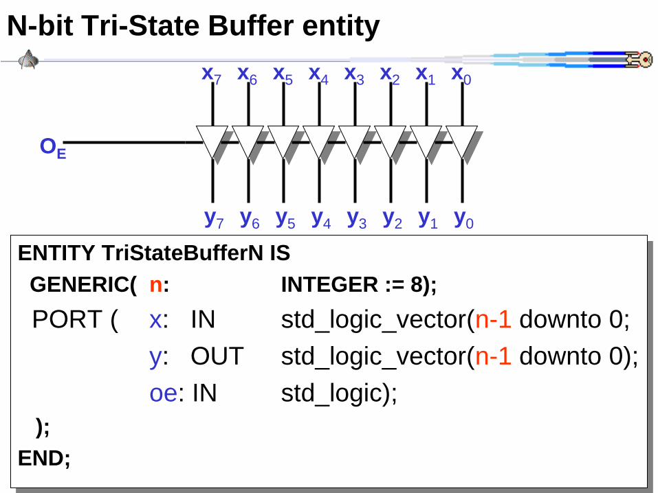
N-bit Tri-State Buffer entity
ENTITY TriStateBufferN IS
GENERIC( n: INTEGER := 8);
PORT ( x: IN std_logic_vector(n-1 downto 0;
y: OUT std_logic_vector(n-1 downto 0);
oe: IN std_logic);
);
END;
y7 y6 y5 y4 y3 y2 y1 y0
OE
x7 x6 x5 x4 x3 x2 x1 x0
CWRU EECS 317
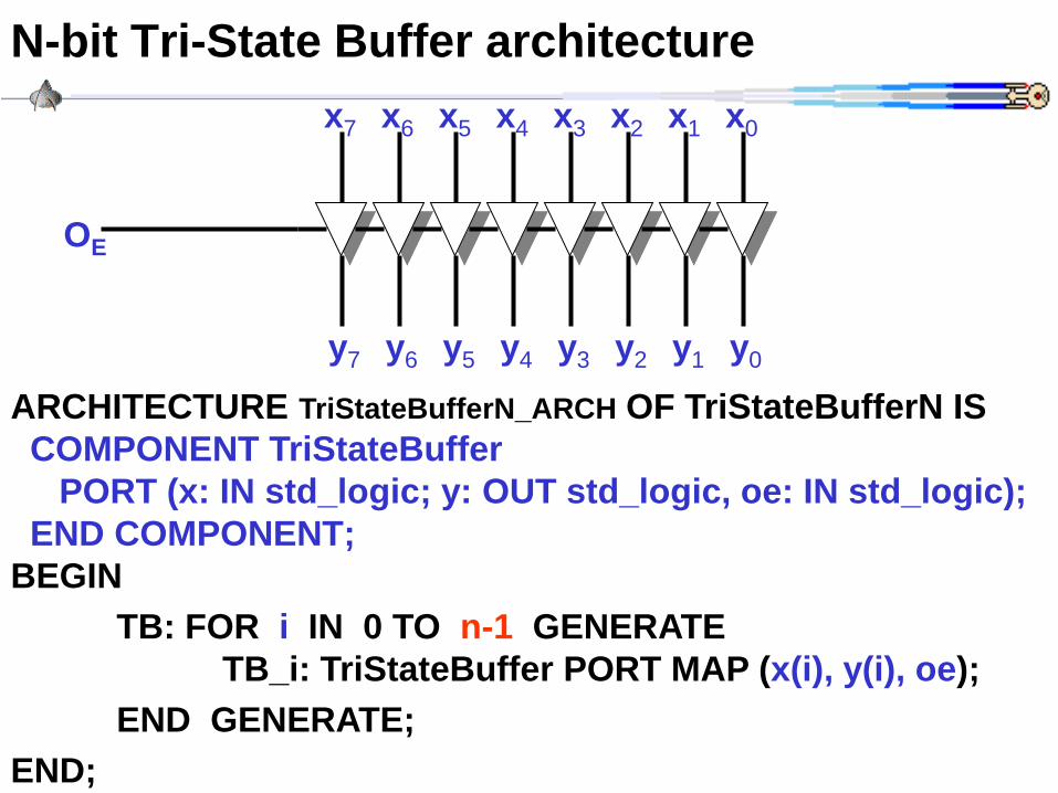
N-bit Tri-State Buffer architecture
ARCHITECTURE TriStateBufferN_ARCH OF TriStateBufferN IS
COMPONENT TriStateBuffer
PORT (x: IN std_logic; y: OUT std_logic, oe: IN std_logic);
END COMPONENT;
BEGIN
TB: FOR i IN 0 TO n-1 GENERATE
TB_i: TriStateBuffer PORT MAP (x(i), y(i), oe);
END GENERATE;
END;
y7 y6 y5 y4 y3 y2 y1 y0
OE
x7 x6 x5 x4 x3 x2 x1 x0
CWRU EECS 317
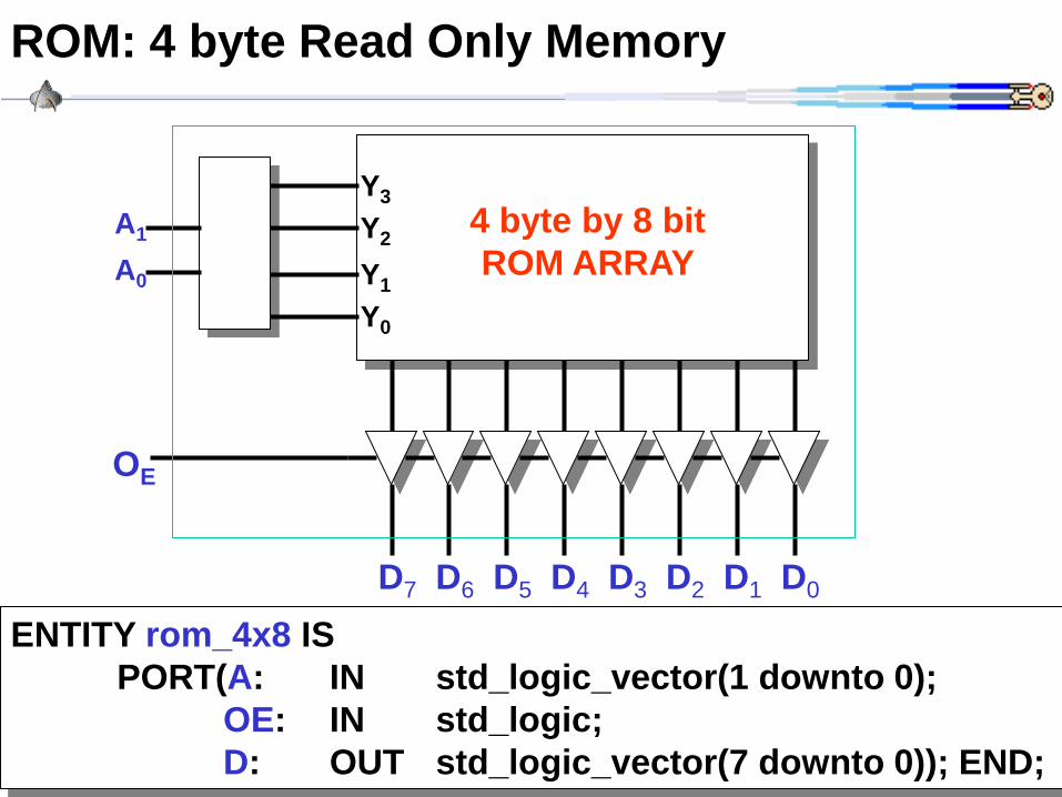
ROM: 4 byte Read Only Memory
Y1
Y0
Y2
Y3
A0
A1
D7 D6 D5 D4 D3 D2 D1 D0
OE
4 byte by 8 bit
ROM ARRAY
ENTITY rom_4x8 IS
PORT(A: IN std_logic_vector(1 downto 0);
OE: IN std_logic;
D: OUT std_logic_vector(7 downto 0)); END;

CWRU EECS 317
ROM: 4 byte Read Only Memory
ARCHITECTURE rom_4x8_arch OF rom_4x8 IS
COMPONENT TriStateBufferN
GENERIC(n: INTEGER := 1);
PORT ( x: IN std_logic_vector(n-1 downto 0;
y: OUT std_logic_vector(n-1 downto 0);
oe: IN std_logic);
END COMPONENT;
SIGNAL ROMout: std_logic_vector(7 downto 0);
BEGIN
BufferOut: TriStateBufferN GENERIC MAP(8)
PORT MAP(ROMout, D, OE);
WITH A SELECT
ROMout <= “01000001” WHEN “00”,
“11111011” WHEN “01”,
“00000110” WHEN “10”,
“00000000” WHEN “11”;
END;
CWRU EECS 317
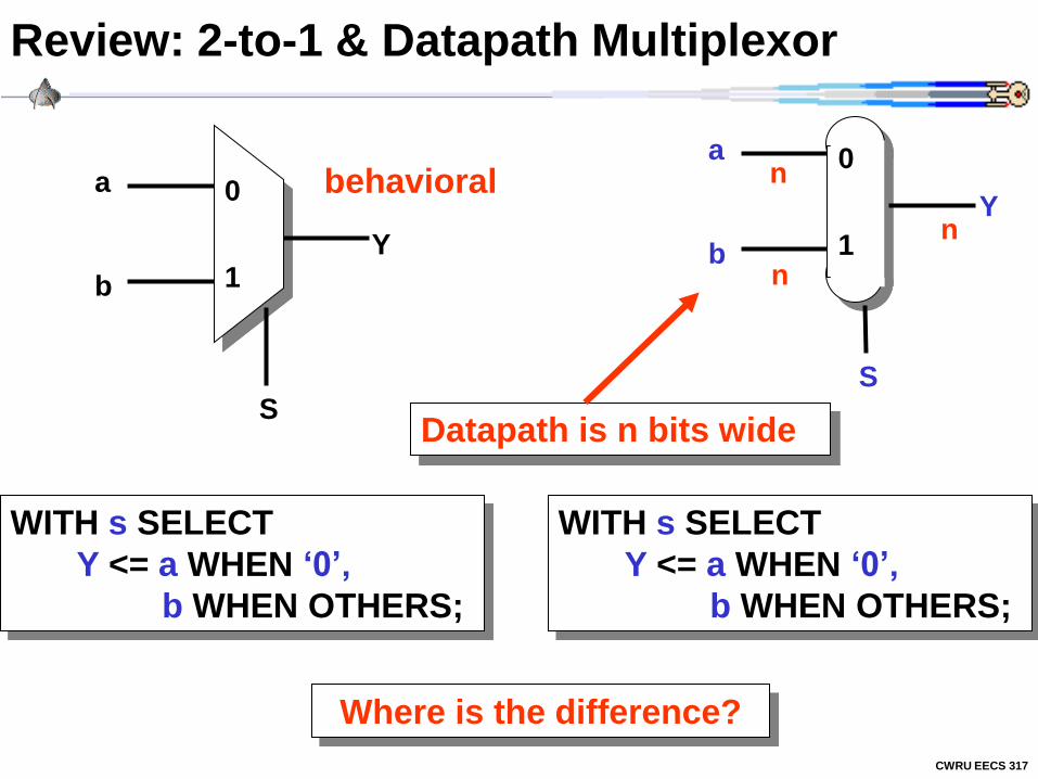
Review: 2-to-1 & Datapath Multiplexor
0
1
a
b
S
Y
WITH s SELECT
Y <= a WHEN ‘0’,
b WHEN OTHERS;
behavioral
WITH s SELECT
Y <= a WHEN ‘0’,
b WHEN OTHERS;
Datapath is n bits wide
Where is the difference?
0
1
a
b
S
Y n
n
n

CWRU EECS 317
Generic 2-to-1 Datapath Multiplexor Entity
0
1
a
b
S
Y n
n
n LIBRARY IEEE;
USE IEEE.std_logic_1164.all;
ENTITY Generic_Mux IS
GENERIC (n: INTEGER);
PORT (Y: OUT std_logic_vector(n-1 downto 0);
a: IN std_logic_vector(n-1 downto 0);
b: IN std_logic_vector(n-1 downto 0);
S: IN std_logic_vector(0 downto 0)
);
END ENTITY;
CWRU EECS 317
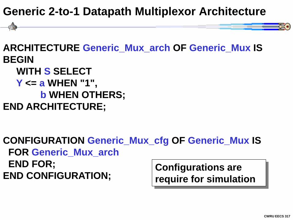
Generic 2-to-1 Datapath Multiplexor Architecture
ARCHITECTURE Generic_Mux_arch OF Generic_Mux IS
BEGIN
WITH S SELECT
Y <= a WHEN "1",
b WHEN OTHERS;
END ARCHITECTURE;
Configurations are
require for simulation
CONFIGURATION Generic_Mux_cfg OF Generic_Mux IS
FOR Generic_Mux_arch
END FOR;
END CONFIGURATION;
CWRU EECS 317
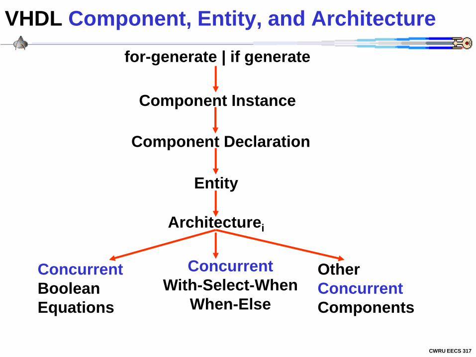
VHDL Component, Entity, and Architecture
Entity
Architecturei
Other
Concurrent
Components
Concurrent
Boolean
Equations
Component Instance
Component Declaration
for-generate | if generate
Concurrent
With-Select-When
When-Else

CWRU EECS 317
Summary of VHDL Components
Component Declaration
COMPONENT component_entity_name
[ GENERIC ( { identifier: type [:= initial_value ]; } ) ]
[ PORT ( { identifier: mode type; } ) ]
END;
[ Optional ] { repeat }
Component Instance
identifier : component_entity_name
[ GENERIC MAP ( identifier { ,identifier } ) ]
[ PORT MAP ( identifier { ,identifier } ) ]
;
mode := IN | OUT | INOUT
type := std_logic | std_logic_vector(n downto 0) | bit
Add ; only if another identifier
CWRU EECS 317
Assignment #4
a) Write an N-bit ALU (default N=8) using the vhdl code of
assignment #3 and then run (N=8) using vhdlan and vhdlsim
assigns. The initial carry-in is set to zero and the final carry
out is not needed. The N-bit ALU should only have x(n), y(n),
s(n) and f. For multiple bits (i.e. std_logic_vector) use:
assign “00101111” Y #binary
or
assign X”2f” Y #hex notation
Write a one useful test case for each function. Make sure it
gives the correct results (i.e. please debug your ALU)! Hand
in the source files and session using the Unix script
command.
b) Write an 8-bit ALU test bench in VHDL and hand in the
source files and session using the Unix script command.