Lecture 2: Topological Analysis of Networks - UCCgprovan/CS6323/2014/L2-Topology.pdf · Lecture 2:...
51
CS 6323 Complex Networks and Systems: Modeling and Inference Lecture 2: Topological Analysis of Networks Prof. Gregory Provan Department of Computer Science University College Cork
Transcript of Lecture 2: Topological Analysis of Networks - UCCgprovan/CS6323/2014/L2-Topology.pdf · Lecture 2:...

CS 6323
Complex Networks and Systems:
Modeling and Inference
Lecture 2:
Topological Analysis of
Networks
Prof. Gregory Provan
Department of Computer Science
University College Cork
How to Characterise Networks?
• Three issues
– Complexity: measure of network “density”
– Performance: what is target QoS?
– Dependability: how reliable is the network functionality
• Issues are in constant tension
• Examine how to define good tradeoffs
CS 6323, Complex Networks and SystemsUniversity College Cork,Gregory M. Provan
2
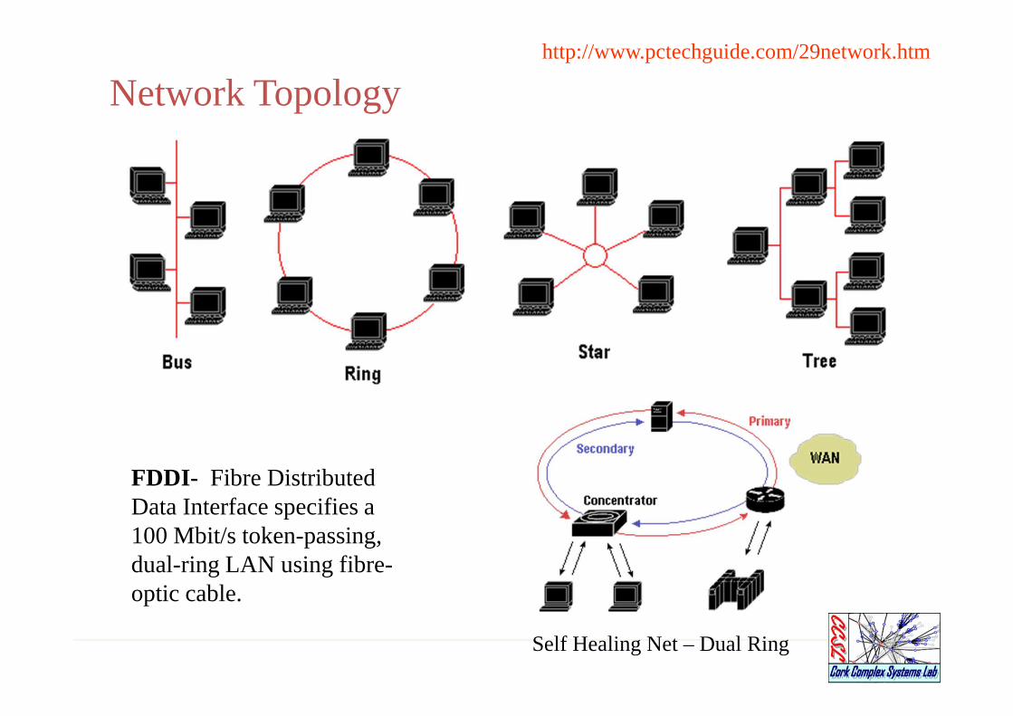
What is a Topology?
� “The way in which the connections are made among all
the network entities is called the topology of the
network”.
� Network topology specifically refers to the physical
layout of the network,
� e.g., the location of the computers and how the cable is run
between them.
� The most common topologies are
� Bus
� Star
� Ring
� Mesh.
Network Topologies
• Regular networks
– Grids, rings, etc.
• Real networks
– Power-law topologies
• Properties of real networks
• Designing networks with particular properties
Issue 1: Network Complexity
• Goals:
– characterise networks using a measure of “complexity”
– Examine properties of different network topologies
– Study how to generate networks with target properties
• Graph generators
CS 6323, Complex Networks and SystemsUniversity College Cork,Gregory M. Provan
5

Issues
• Regular networks are most commonly studied
– Easy to study
• Problem
– Real networks are not regular
– Possess power-law structure
• Examples
– Internet
– Communications networks
– Social networks (facebook)
– Airline, road networks
http://www.pctechguide.com/29network.htm
FDDI- Fibre Distributed Data Interface specifies a 100 Mbit/s token-passing, dual-ring LAN using fibre-optic cable.
Network Topology
Self Healing Net – Dual Ring

Regular Networks
• Standard approach for networking
– Bus
– Star
– Ring
• Methods for creating “simple” networks
– Simple “models”

Bus Topology
• The bus topology is the simplest and most common.
• It is often used when a network installation is small,
simple, or temporary.
• It is a Passive topology. This means that computers on the
bus only listen for data being sent, they are not
responsible for moving the data from one computer to
the next.

BUS Topology
Computer
Computer
Computer Computer
Computer Computer
Bus Topology
� In an active topology network, the computers regenerate
signals and are responsible for moving the data through
the network.
� On a bus network, all the computer are connected to a
single cable.
� When one computer sends a signal using the cable, all the
computers on the network receive the information, but
only one (Addressee) accepts it. The rest disregard the
message.

Advantages of Bus
• The bus is simple, reliable in very small network, and
easy to use.
• The bus requires the least amount of cable to connect
the computers together and is therefore less expensive
than other cabling arrangements.
• Failure of one node does not affect the rest of network.
• Failure of the bus system causes the entire network to
crash
Disadvantages of Bus
• Heavy network traffic can slow a bus considerably.
• A break in the cable or lake of proper termination can
bring the network down.
• It is difficult to troubleshoot a bus.

Appropriateness
• The network is small
• The network will not be frequently reconfigured
• The least expensive solution is required
• The network is not expected to grow much
Star Topology
Hub
Computer
Computer
ComputerComputer
Server
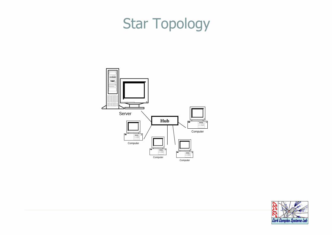
Star Topology
� In a star topology, each device has a dedicated point to point
link only to central controller, usually called a
hub/server/host.
� Each computer on a star network communicates with a central
hub that resends the message appropriate computer(s)
� The hub can be active or passive.
� An active hub regenerate the electrical signal and sends it to
all the computers connected to it.

Star Topology
• This type of hub is often called a multiport repeater.
• Active hub require electrical power to run.
• A passive hub, such as wiring panels, merely acts as a
connection point and does not amplify or regenerate the
signal.
• Passive hubs do not require electrical power to run.

Advantages of Star Topology
� It is easy to modify and add new computers to a star network
� During adding/deleting a node network can function normally.
� When the capacity of the central hub is exceeded, it can be
replaced with one that has a larger number of ports to plug
lines into.
� Provide for centralised monitoring and management of the
network.
� Single computer failure do not necessarily bring down the
whole star network.
Disadvantages of Star Topology
• If the central hub fails, the whole network fails to
operate.
• It costs more to cable a star network.
• Require dedicated server and hub

Appropriateness
• It must be easy to add or remove client computer.
• It must be easy to troubleshoot.
• The network is large.
• The network is expected to grow in the future.
Ring Topology
Computer
Computer
Computer
Computer
Computer

Ring Topology
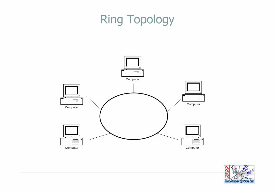
• In a ring topology, each computer is connected directly to the next
computer in line, forming a circle of cable.
• It uses tokens to pass the information from one computer to another.
• Every computer is connected to the next compute in the ring, and
each retransmits what it receives from the previous computer.
• The message flows around the ring in one direction.
• Rings are an active topology.
– There is no termination because there is no end to the ring

Token Passing
• Token passing a method of sending data in a ring topology
• A small packet, called the token passed around the ring to
each computer in tern
• If a computer has information to send, it modifies the token,
adds address information and the data and sends it down the
ring.
• The information travels around the ring until it either reaches
its destination or returns to the sender.
• A token can circle a ring 200 meters in diameter at about
10,000 times a second.

Advantages of Ring Topology
• All the computers have equal access to the network.
• Even with many users, network performance is even
• Allows error checking, and acknowledgement.

Disadvantages of Ring Topology
• Failure of one computer can affect the whole network.
• It is difficult to troubleshoot the ring network.
• Adding or removing computers disturbs the network.

Appropriateness
• The network must operate reasonably under a heavy load
• A higher-speed network is required.
• The network will not be frequently reconfigured.

Mesh Topology
Computer
Computer Computer
ComputerComputer

Mesh Topology
• In a mesh topology, every device has a dedicated point-
to-point link to every other device.
• A fully connected mesh network therefore has n(n-1)/2
physical channels to link n devices.
• To accommodate that many links, every device on the
network must have n-1 input/output ports.
Advantages of Mesh Topology
� Because of the dedicated link, no traffic between
computers.
� Failure of one node computer does not affect the rest of
the network.
� Because of the dedicated link, privacy and security are
guaranteed
� Point-to-point links make fault identification and fault
isolation easy.

Disadvantages of Mesh Topology
• Due to the amount of cabling and number of input output
ports, it is expensive.
• Significant space is required to run the cables.
Variations of the Major Topologies
• Star Bus
– Combines bus and star
• Hybrid Star
– A star network can be extended by placing another star hub
where a computer might otherwise go, allowing several more
computers or hubs to be connected to that hub.

Star BusHub HubHub
Computer
Computer
Computer
Computer
Computer ComputerComputer
Computer
Computer
Computer
– The star bus topology combines the bus and the star, linking
several star hubs together with bus trunks. If one computer fails,
the hub can detect the fault and isolate the computer.
– If a hub fails, computers connected to it will not be able to
communicate, and the bus network will be broken into two
segments that can not reach each other.
Variations of the Major Topologies
• Hybrid Topologies
– Often a network combines several topologies as subnetworks
linked together is a large topology.
– For instance one department of business may have decided to use
a bus topology while another department has a ring.
– The two can be connected to each other a central controller in a
star topology
– When two or more topologies are connected together it forms a
hybrid topology

PDA
BSC(Base Station
Controller, Preprocessing)BST
WirelessSensor
Machine Monitoring
Medical Monitoring
Wireless SensorWireless
Data Collection Networks
Wireless(Wi-Fi 802.11 2.4GHz
BlueToothCellular Network, -
CDMA, GSM)
Printer
Wireland(Ethernet WLAN,
Optical)
Animal Monitoring
Vehicle Monitoring
Onlinemonitoring Server
transmitter
Any where, any time to access
Notebook Cellular Phone PC
Ship Monitoring
Wireless Sensor Networks
RovingHumanmonitor
Data Distribution
Network
Management Center(Database large storage,
analysis)Data Acquisition
Network
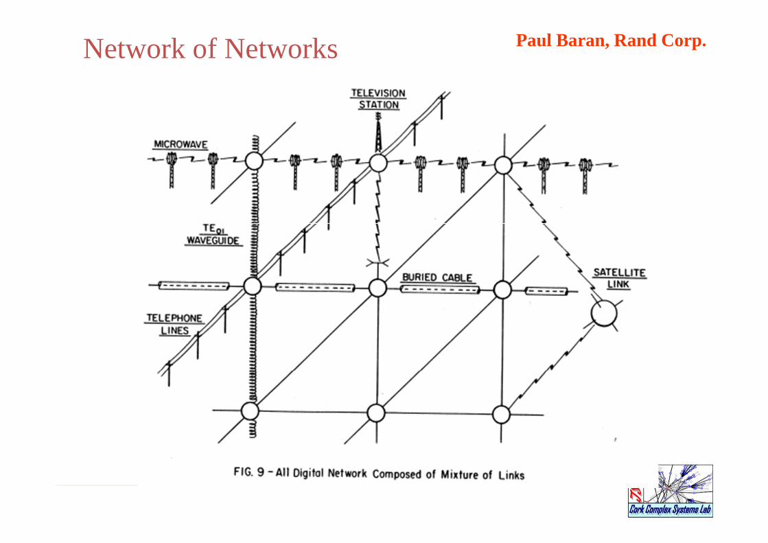
Paul Baran, Rand Corp.Network of Networks
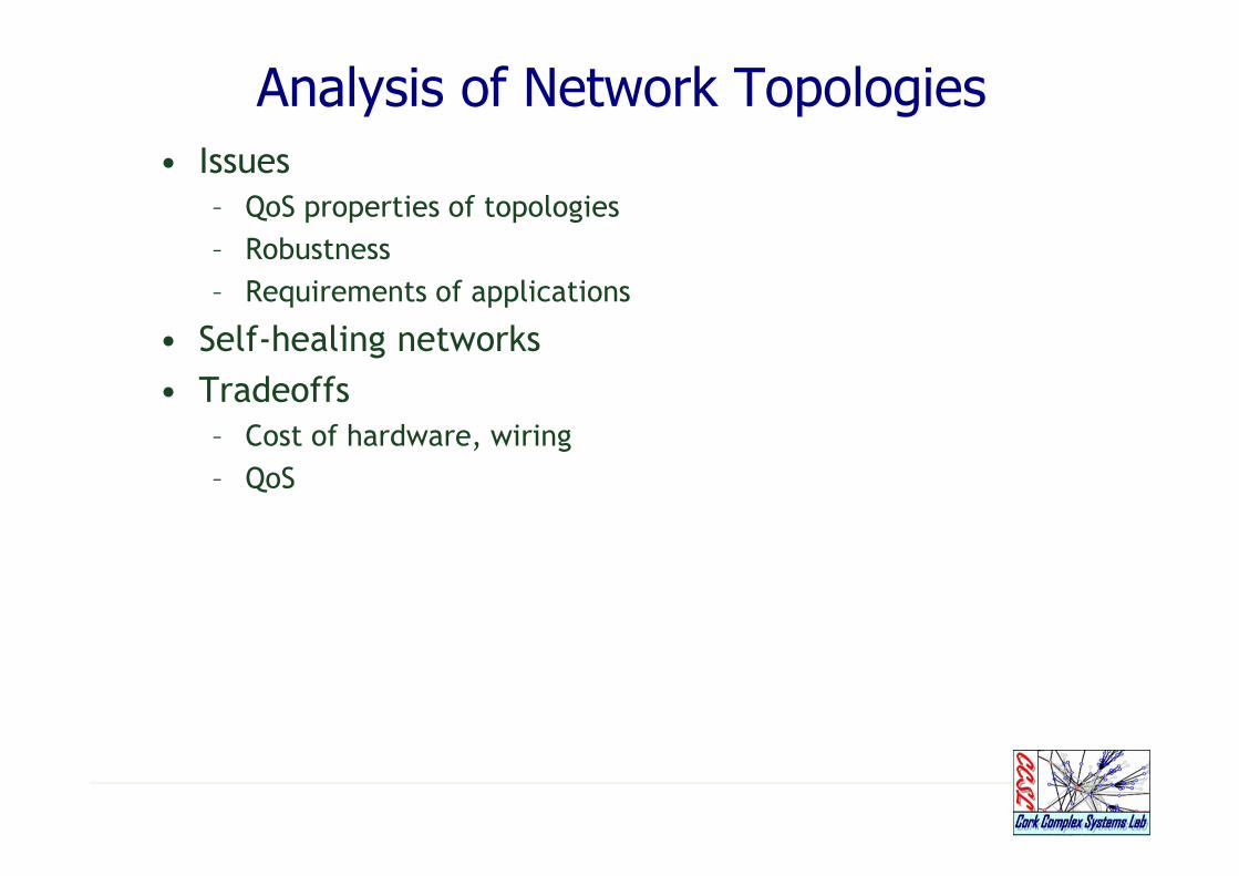
Analysis of Network Topologies
• Issues
– QoS properties of topologies
– Robustness
– Requirements of applications
• Self-healing networks
• Tradeoffs
– Cost of hardware, wiring
– QoS

http://www.fiber-optics.info/articles/its-networks.htm
Bus Network with Backbone Interconnections Between Different Network Types
Token Ring Network Topology Self-healing Ring TopologyTwo rings
Star Network Topology
Applications and Network Topology
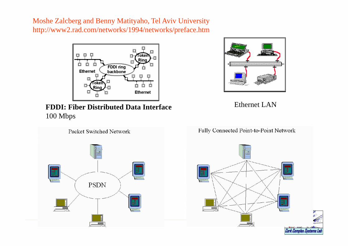
Ethernet LANFDDI: Fiber Distributed Data Interface100 Mbps
Moshe Zalcberg and Benny Matityaho, Tel Aviv Universityhttp://www2.rad.com/networks/1994/networks/preface.htm
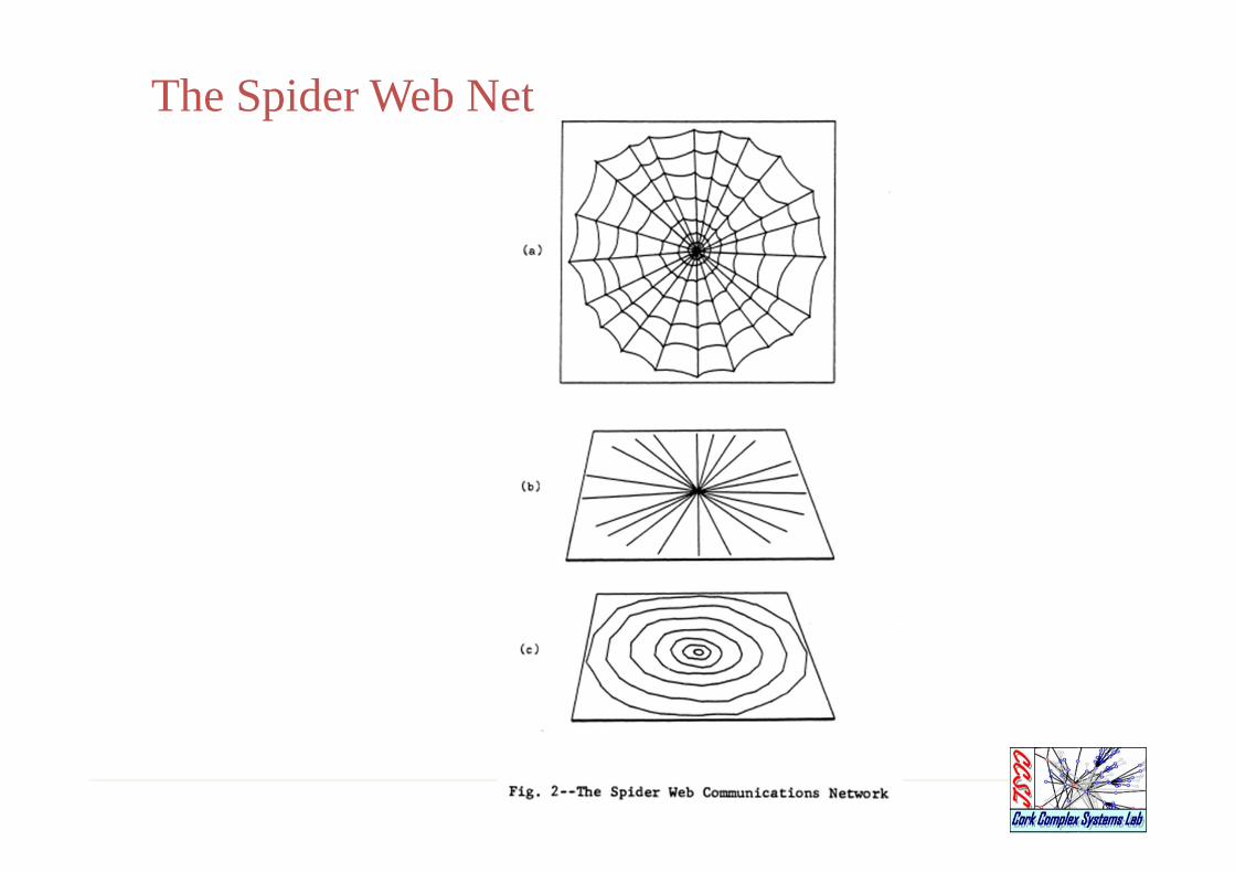
The Spider Web Net

Centralized, Decentralized, Distributed
Neighbor Connectivity and RedundancyNetwork Topology

Connectivity and Number of Links
Number of links increases exponentially

Basic 4-link ring element
Two ways to interconnect two rings
Two 2-D mesh networks
Mesh Networks
Standard ManhattanNew TopologyAlternating 1-way streetsEdge Binding- In any network, much of the routing power of peripheral stations is wasted simply because peripheral links are unused. Thus, messages tend to reflect off the boundary into the interior or to move parallel to the periphery.
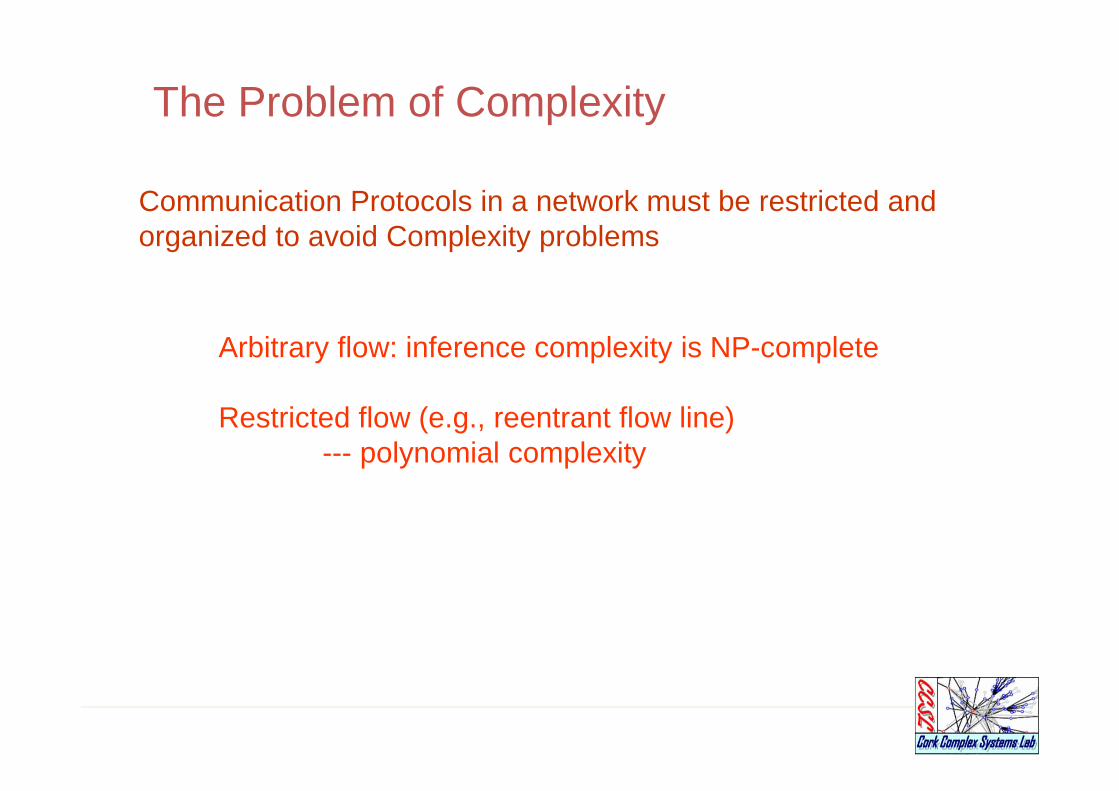
The Problem of Complexity
Communication Protocols in a network must be restricted and organized to avoid Complexity problems
Arbitrary flow: inference complexity is NP-complete
Restricted flow (e.g., reentrant flow line)--- polynomial complexity
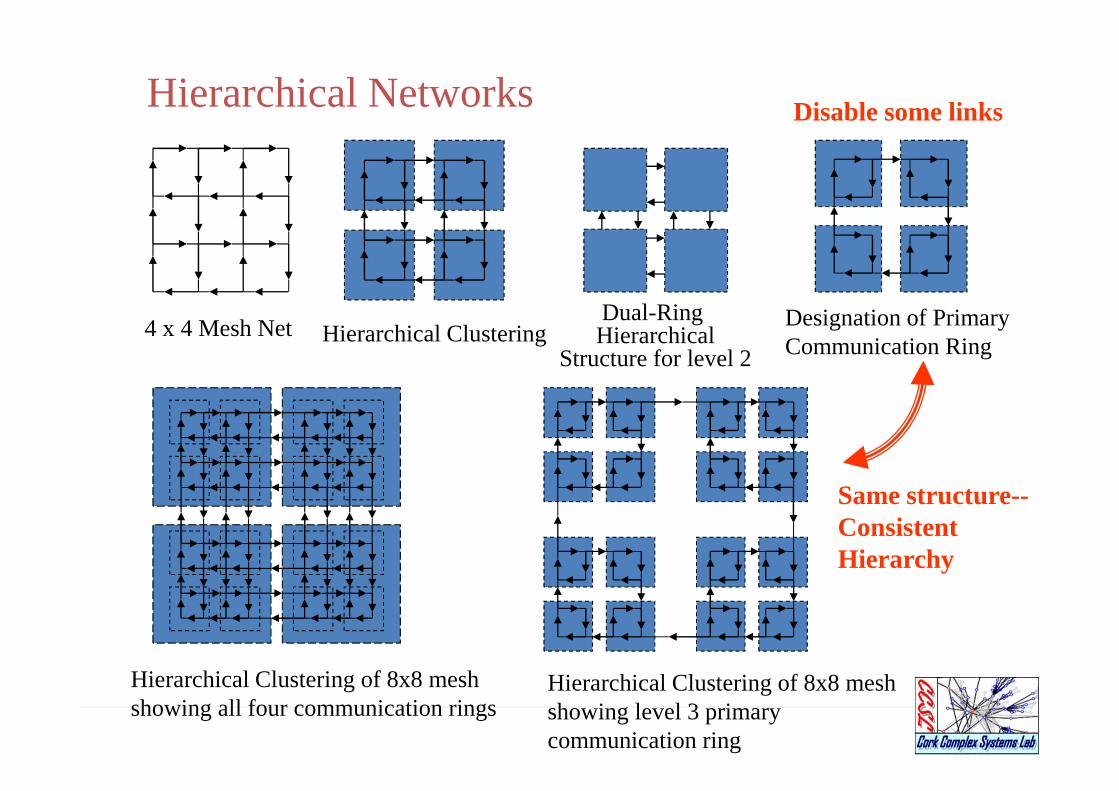
Hierarchical Networks
Hierarchical ClusteringDual-Ring Hierarchical
Structure for level 2
Designation of Primary Communication Ring
Hierarchical Clustering of 8x8 meshshowing level 3 primary communication ring
Hierarchical Clustering of 8x8 meshshowing all four communication rings
4 x 4 Mesh Net
Disable some links
Same structure--ConsistentHierarchy
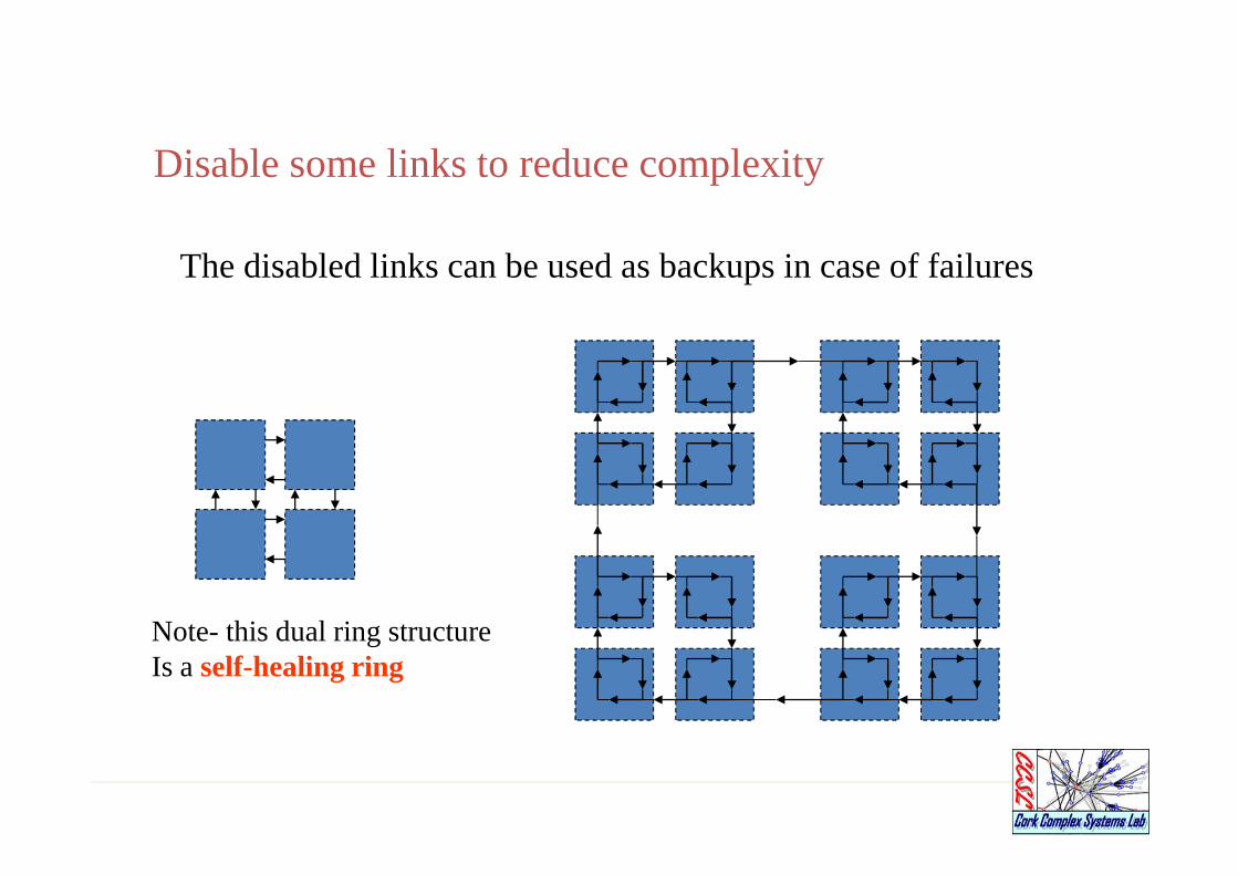
Disable some links to reduce complexity
The disabled links can be used as backups in case of failures
Note- this dual ring structureIs a self-healing ring
2011-9-22.4646
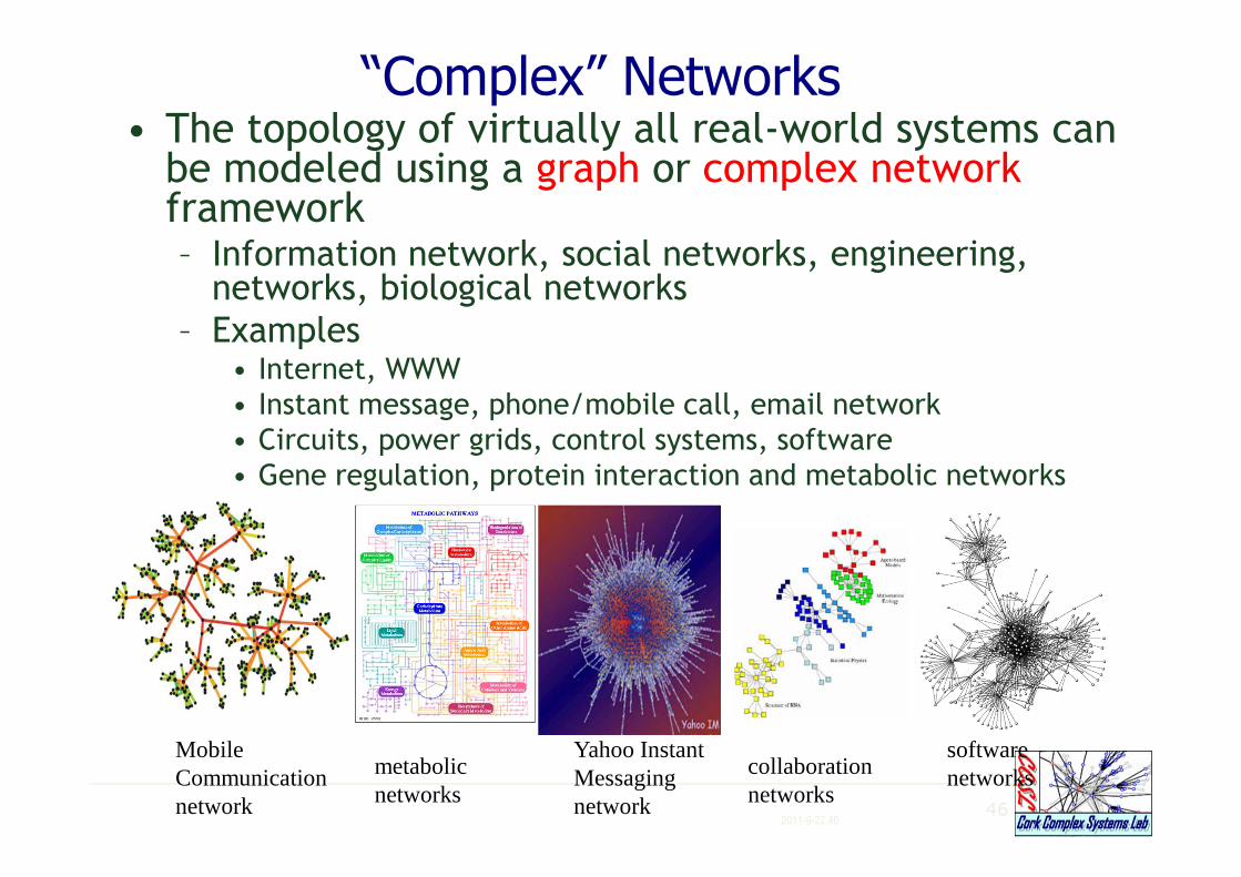
“Complex” Networks• The topology of virtually all real-world systems can be modeled using a graph or complex networkframework– Information network, social networks, engineering, networks, biological networks
– Examples• Internet, WWW
• Instant message, phone/mobile call, email network
• Circuits, power grids, control systems, software
• Gene regulation, protein interaction and metabolic networks
Mobile Communication network
metabolic networks
Yahoo Instant Messaging network
collaboration networks
software networks
47
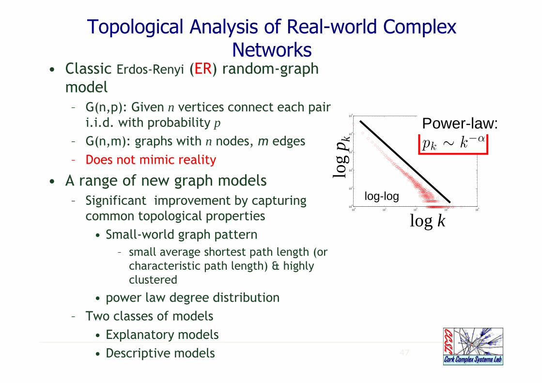
Topological Analysis of Real-world Complex Networks
• Classic Erdos-Renyi (ER) random-graph
model
– G(n,p): Given n vertices connect each pair i.i.d. with probability p
– G(n,m): graphs with n nodes, m edges
– Does not mimic reality
• A range of new graph models
– Significant improvement by capturing
common topological properties
• Small-world graph pattern
– small average shortest path length (or
characteristic path length) & highly
clustered
• power law degree distribution
– Two classes of models
• Explanatory models
• Descriptive models
100
101
102
103
104
100
101
102
103
104
105
log-log
log
p k
log k
Power-law:

Network types
• Ethernet (1970)
• Fast ethernet (1995)
• Token rings (1994)
• Gigabit ethernet (1999)
EthernetEthernet was developed in the mid 1970's by the Xerox Corporation, and in 1979 Digital Equipment Corporation DEC) and Intel joined forces with Xerox to standardise the system. The Institute of Electrical and Electronic Engineers (IEEE) released the official Ethernet standard in 1983 called the IEEE 802.3 after the name of the working group responsible for its development, and in 1985 version 2 (IEEE 802.3a) was released. This second version is commonly known as "Thin Ethernet" or 10Base2, in this case the maximum length is 185m even though the "2" suggest that it should be 200m.
Fast EthernetFast Ethernet was officially adopted in the summer of 1995, two years after a group of leading network companies had formed the Fast Ethernet Alliance to develop the standard. Operating at ten times the speed of regular 10Base-T Ethernet, Fast Ethernet -also known as 100BaseT - retains the same CSMA/CD protocol and Category 5 cabling support as its predecessor higher bandwidth and introduces new features such as full-duplex operation and auto-negotiation.
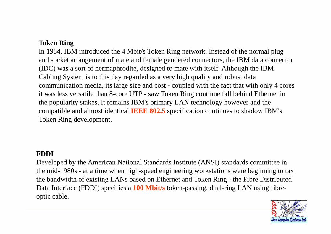
FDDIDeveloped by the American National Standards Institute (ANSI) standards committee in the mid-1980s - at a time when high-speed engineering workstations were beginning to tax the bandwidth of existing LANs based on Ethernet and Token Ring - the Fibre Distributed Data Interface (FDDI) specifies a 100 Mbit/s token-passing, dual-ring LAN using fibre-optic cable.
Token RingIn 1984, IBM introduced the 4 Mbit/s Token Ring network. Instead of the normal plug and socket arrangement of male and female gendered connectors, the IBM data connector (IDC) was a sort of hermaphrodite, designed to mate with itself. Although the IBM Cabling System is to this day regarded as a very high quality and robust data communication media, its large size and cost - coupled with the fact that with only 4 cores it was less versatile than 8-core UTP - saw Token Ring continue fall behind Ethernet in the popularity stakes. It remains IBM's primary LAN technology however and the compatible and almost identical IEEE 802.5 specification continues to shadow IBM's Token Ring development.
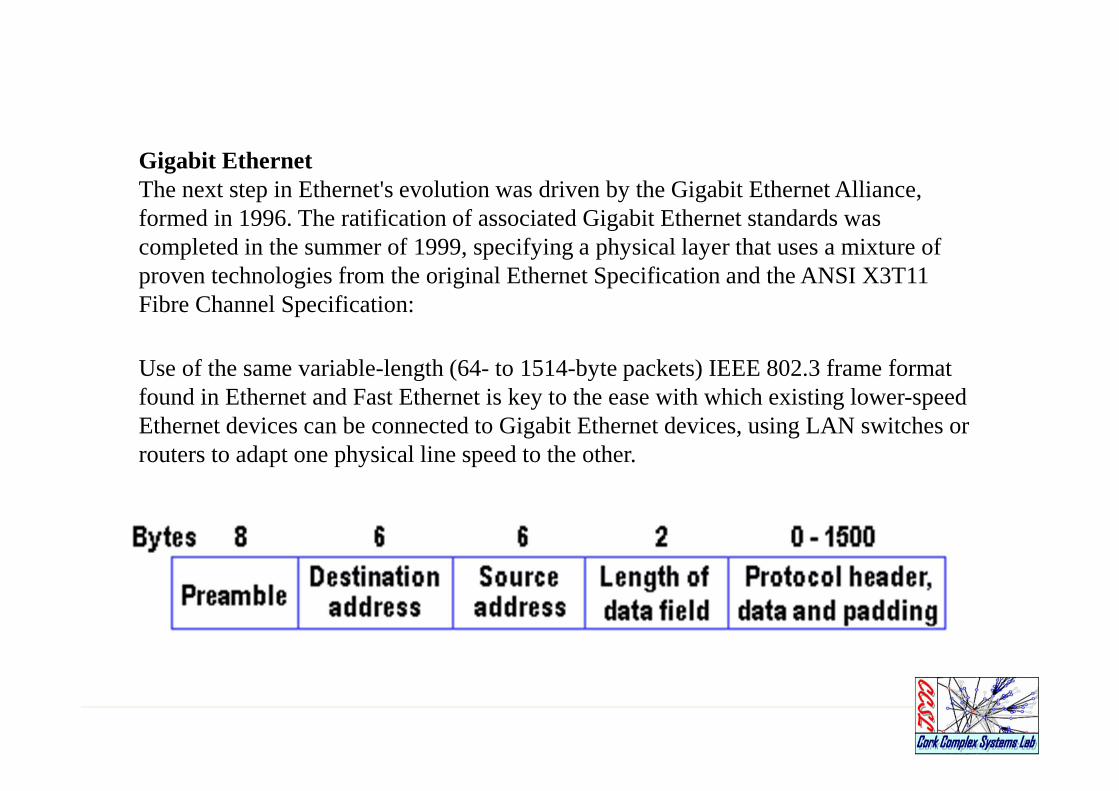
Gigabit EthernetThe next step in Ethernet's evolution was driven by the Gigabit Ethernet Alliance, formed in 1996. The ratification of associated Gigabit Ethernet standards was completed in the summer of 1999, specifying a physical layer that uses a mixture of proven technologies from the original Ethernet Specification and the ANSI X3T11 Fibre Channel Specification:
Use of the same variable-length (64- to 1514-byte packets) IEEE 802.3 frame format found in Ethernet and Fast Ethernet is key to the ease with which existing lower-speed Ethernet devices can be connected to Gigabit Ethernet devices, using LAN switches or routers to adapt one physical line speed to the other.


![Topological Analysis of Biological Networks · 2012-05-10 · [74] and providing comprehensive topological analysis of biomolecular networks, we have developed two applications, related](https://static.fdocuments.us/doc/165x107/5f8a94b8350c2073ee0195c7/topological-analysis-of-biological-networks-2012-05-10-74-and-providing-comprehensive.jpg)