LECTURE 1: REACTOR DESIGN PHILOSOPHIES Library/20042101.pdfReactorPhysics and Fuelling Dr. Giovanni...
18
Reactor Physics and Fueiling Dr. Giovanni (John) Brenciagfia page1-1 Lgcture 1: Reactor Design Phifosophies OBJECTIVES: LECTURE 1: REACTOR DESIGN PHILOSOPHIES At the end of this lecture, you will be able to describe how the following core characteristics are set by the design philosophy of CANDU reactors: 1. Fuel 2. Coolant 3. Moderator 4. Reactivity devices Department of Nuclear Technology Faculty of Engineering Chulalongkom University
Transcript of LECTURE 1: REACTOR DESIGN PHILOSOPHIES Library/20042101.pdfReactorPhysics and Fuelling Dr. Giovanni...

Reactor Physics and FueilingDr. Giovanni (John) Brenciagfia page1-1 Lgcture 1: Reactor Design Phifosophies
OBJECTIVES:
LECTURE 1: REACTOR DESIGN PHILOSOPHIES
At the end of this lecture, you will be able to describe how the following core characteristics are set by thedesign philosophy of CANDU reactors:
1. Fuel
2. Coolant
3. Moderator
4. Reactivity devices
Department of Nuclear Technology Faculty of Engineering Chulalongkom University
Reactor Physics and FuellingDr. Giovanni (John) Brenciaglia
\,
page1-2 Lecture 1: Reactor Design Philosophies
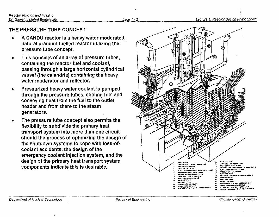
THE PRESSURE TUBE CONCEPT
• A CANDU reactor is a heavy water moderated,natural uranium fuelled reactor utilizing thepressure tube concept.
• This consists of an array of pressure tubes,containing the reactor fuel and coolant,passing through a large horizontal cylindricalvessel (the calandria) containing the heavywater moderator and reflector.
• Pressurized heavy water coolant is pumpedthrough the pressure tubes, cooling fuel andconveying heat from the fuel to the outletheader and from there to the steamgenerators.
• The pressure tube concept also permits theflexibility to subdivide the primary heattransport system into more than one circuitshould the process of optimizing the design ofthe shutdown systems to cope with loss-ofcoolant accidents, the design of theemergency coolant injection system, and thedesign of the primary heat transport systemcomponents indicate this is desirable.
Department of Nuclear TechnOlogy Faculty of Engineering Chulalongkorn University

Reactor Physics and FuellingDr. Giovanni (John) Brenciaglia pAge 1·3 Leciure 1: Reactor Design Philosophies
/, 'I" y(I::::" (Q) Q),...........,,.'
1:=''' 1::::" 11;:::~1l~_~ l,--,~I '':.!.1"-
_ Reactivity device Low pressure
"'':::-v 6:=~\ (t:'" moderator/.':='1 'r'::: II II ~=!IIL,) I, ,I
~=,1 ..:..~/
'- "'.=;1 Fuel & coolant
Calandria tube{/ «~)I
(1"')'/ (Q) (Q),~,.I ~Gasgap
Pressure tube28.6 em
0 ."I';::~ 0 i 11--(~_/) " /
PRESSURE AND CALANDRIA TUBES
• Each pressure tube is isolated and insulated fromthe heavy water moderator by a concentric calandriatUbe.
• The annular space between the pressure andCalandria tubes is filled with gas. This configurationresults in the moderator system being operatedindependently of the high temperature, highpressure coolant in the pressure tube.
• The heat generation ir, the moderator is very lowthus obviating the need for a high-strength pressurevessel.
• Due to the physical separation of coolant andmoderator the latter operates at the relatively cooltemperature of approximately 70°C. This means thatthp. cool moderator can act as the heat sink undercertain accident conditions.
• The reactivity and control devices which are positioned interstitially betvleen the pressure tubesoperate in a low pressure low temperature environment.
• Should pressure tube leaks develop they can readily be detected by monitoring the moisture content inthe gas space between the pressure tube and the calandria tube. This is normally done on acontinuous basis.
• The pressure tube concept also makes it possible to detect release of fission products from the fuel inan individual fuel channel due to cladding defects withollt shutting down the reactor.
Department of Nuclear Technology Faculty of Engineering Chulalongkorn University
"".. ", ,,,'",, .. , '" ,., .. """,,, '"'''''''''' .. ",","''''''

Reactor Physics and FuellingDr. Giovanni (John) BrenciagUa page 1- 4 Leclure 1: Reaclor Design Philosophies
REACTOR CALANDRIA
• The calandria is a horizontal cylindrical shell theprimary. purpose of which is to support the fuelchannels assemblies and to contain the heavywater moderator and reflector.
• The calandria also supports guide tubes forreactor devices and in-core instrumentation.These pass between the calandria tubes and aretherefore situated in a low-pressureenvironment.
• The calandria is provided with pressure reliefvalves as part of a cover gas system whichregulates pressure of the moderator systemunder normal operation. Rupture discs locatedat the end of the four pressure relief pipes limitthe pressure rise in the calandria that wouldoccur in the event of an accidental rupture of apressure and calandria tube, although theprobability of this actually happening is verysmall.
• The calandria assembly is embedded within thelight water filled carbon-steel lined concretevault.
• At each end of the calandria shell is an endshield containing biological shielding material inthe form of carbon steel balls and light water.
_~ l .' ,
"'<::eS
OflOINAfty CO"fC1'I1T1
Department of Nuclear Technology Facully of Engineering Chula/ongkorn University

Reactor PhysIcs and FuellingDr. Giovanni (John) BrenciagUa page 1-5 Lecture 1: Reactor Design Philosophies
- I Total MaximumFunction Device Reactivity Reactivity
Worth (mk)" Rate (mk/s)
Control 14 Zone Controllers 7 ± 0.14Control 21 Adjusters 15 ± 0.1Control 4 Mechanical Control ± 0.0075 (driving)
Absorber 10 - 3.5 (dropping)Control Moderator Poison - ± 0.01 (extracting)
Safety ,28 Shutoff Units 80 - 50Safety I Poison Injection >300 - 50_I Nozzles
REACTIVITY DEVICES
• The primary method used to control the reactivity of CANDU reactors is through on-line refuelling whichoccurs on a daily basis.
• In the 600 MWe CANDU PHW there are six means of changing the reactivity state of the core besidesrefuelling:
=> four are used for normal control functions including controlled shutdown(a) 14 liquid zone controllers (H20 filled compaltments)(b) 21 adjuster rods(c) 4 mechanical control
absorbers(d) moderator poison
=> two are used by special safetysystems for rapid shutdown duringaccident conditions. ;(a) 28 cadmium shutoff rods in one
shutdown system(b) 6 nozzles which permit rapid
injection of gadolinium solutioninto the moderator which·comprise a second, completelyindependent shutdown system.
.. 1 mk is a~ value of 0.001 or 0.1%
Departmenl of Nuclear Technology Faculty of Engineering Chulalongkorn University
" 'U'",," " "',,. ',,' "" """"'''''''' "~.,".,,,.. ,, ,

Reactor Physics and FuellingDr. Giovanni (John) Brenciaglia page 1 - 6 Lecture 1: Raacto,. Design Philosophies
'. I ~ • ",
~ .. ".".
.. . :. ~ .
. ,' ... '.. '.
,'.' f,- ••~•
.'..•••••••• : <
/.: ::: ~;:' :••• :',' I.... ~. ~
.' ". I~.. ' , ..~', .' .
"0.'
.1.,', '" .
F:::.;C·:·;:.r.·' ..
MOOER"TOR ~:.::::.<:,:lN~ET '~':;' ;:. :-
LIGHTWATER
SHIEL~
I-------l f---'""'-~~~...>.......," .'
TVPICAL AIII\ANGEMENT fOillIiA(:T,,,IY'" MECHANISM DECK ZONE ,ONTIIOL "NO VEIITlCAL
FLUX DElECTOI'I UNITS
/
llVPTUIIE D"C' OEe- W'B 'OINT- TI) YAULf
ASS£MBLY
" .. "
TYPICI\L A~RI\IIIGEMENT
Fall SHVTOH ADJUSTeRM'O CONrROL "as(ll'lOEII UNIT$
""--
:.' "
. '.~ . ..
.. ,.: '...
.. '
.' ..' '.
'. LIClJlO POISON.. .'.. ,... " . '.. INJECTION
. ". !, .. SHUTOOWN UNIT
\.... :;.... ". ... 0","00'"''''
d';":' .. .
Reactivity Devices (continued)
• All reactivity devices are located or introducedinto guide tubes permanently positioned in thelow-pressure moderator environment.
• The guide tubes are located interstitiallybetween rows of calandria tubes.
• There exists no mechanism for rapidly ejectingany of these rods, nor can they drop out of thecore. This is a distinctive safety feature of thepressure tube reactor design.
• The maximum reactivity rates achievable bydriving all control devices together is about .35mklsecond, which is well within the designcapability of the shutdown systems.
Department of Nuclear Technology FaCUlty of Engineering Chulalongkom University

Reactor PhYSIcs end FuellingDr, Giovanni (John) Brenciaglia paget-7 Lecture 1: Reactor Design Philosophies
Reactivity Devices (continued)
INOSHIU,O",IUOMIIOlT filiNG
ALAHORIA SUISHElL
CAI.ANORIA .....IN 'IlEU
CALANO'.....VA",I,T 1,1"'10.
:!',';<,":?']./
•
•o
TyflC.... THI""U '0",1'I'....:11V,T .... COHTfIl01. UI<IT
HOI"CQNT~·
'1."')llI"'~C,=::t--t---jl----••--E~--'":::::E==E"=:'F-=-
I.-lOU1Cl I....J.CTIOH'''VTOO_ N01UI
IOff ("' ........ " _.r.-::"'-JHO.... ' .. Ci
PlO $HI'LQlCAl.~NO''IfA
SIDE TUllE ''''E£T
aooo«lI...'Ofil INion[NO SlolllLOi'UlEllltolGSIDE lU'E SHEET
::;.:
'.';';:~."
\..~.
';'~
o ZONE CONTROl.. UNIT (6)
~ CONTROL ABSOR8ER UNIT (4)
e ... IEWING PORr (2)
'j
;";.l
,,'"
IION CHAM8!I'lS
I@. @@@ .@
•·O@.~@~@O·.1:F>. •
@"" @ @~ @.@ ~.@ @ @.
•
• vtRTICAL FLUX UETECTOR UNIT (261
@ ADjUSTER UNIT (21)
~ SHUTOFF UNIT (28)
Department of Nuclear Technology Faculty of Engineering Chulalongkorn University

Reactor Physics and FuellingDr. Giovanni (John) Brenciagfia page 1 -B Lecture 1: Reactor Design Philosophies
+2;-'-----------------------,
ASSUMPTIONS- Calandrla size unchanged- Unilorm displacement 0' all fuel channels- Moderator density and temperatura
unchan[jed
o·
-10
~'E-2
The use of natural uranium fuel and heavy water as moderator and coolantcombilJed with capability to refuel the reactor on power leads to a designcharacterized by good neutron economy, since the fraction of all neutronsproduced which are absorbed in the fuel is high throughout most of the lifeof the reactor.
The fuel channels are arranged on a square lattice with a 286 millimetrepitch. This is a near optimum geometry from a reactivity standpoint.
Figure 1-1 shows the reactivity change of a uniform lattice as a function oflattice pitch.
A consequence of the particular latticegeometry used in the CANDU PHW is thatthe neutron energy spectrum is very wellthermalized.
'"The associated long migration length for g>neutrons and the long neutron lifetime have .g -4
an important bearing on methods used in the z:.~ -6reactor physics analysis and on the ~ ."requirements for the shutdown systems r;;,
-Bfrom the neutronic point-of-view.
•
•
•
•
•
CORE DESIGN DETAILS
. 26 27 26 29Lallice pilch (em)
30 31
Figure 1-1: Variation of Reactivity with Lattice Pitch forCANDU·PHW Lattice.
Department of Nuclear Technology Faculty of Engineering Chula/ongkom University

Reactor Physics end FuellingDr. Giovanni (John) Brenciaglla page 1-1} Lecture 1: Reactor Design Philosophies
't~
fIXED END OFfUEL CHANNelS
1~
10
12
"'"
9
(I, 3
iII, I
I It.. ___ _ __ 4
I I I !,,~t
: I I 4 ~1_0'·'
\---- --I I ••
11, I:-L__ I----..,
'\1 I ,I ,I
\I
I I, ,I
I 5 ,I ,I- IV --:
..............SOS10NTHIS SlOE
LIQUID ZONE CONTROLLERS
• The purpose of the liquid zone control system is toprovide the continuous fine control of the reactivity andhence reactor power level. It is needed becausefuelling is not truly continuous but done in smallincrements (usually at least 8 bundles at one time).
• It also compensates for other minor perturbations inparameters such as temperatures which cause smallreactivity changes.
• This system is also designed to accomplish spatialcontrol of the power distribution which prevents xenoninduced power oscillations in the power distributionfrom developing.
• The system is contained in six vertically oriented tubesrunning interstitially between the fuel channels fromthe top to the bottom of the core. The two central tubesare divided into three compartments each b}-'appropriately placed bulkheads and the four outertubes are divided into two compartments to give a totalof 14 individually controllable compartments in thereactor.
Department of Nuclear Technology Facully of Engineering Chulalongkorn University
Reactor Physics and FuellingDr. Giovanni (John) Brenciagfia page 1 • 10 Lecture 1: Reactor Design Philosophies
" " '"
ZONE10 1
.............. r" I
" I..--'".._--- III
ZONE i• 11 I
" I" I
" I" I......-:'
I .........-:
I II II ZONE :: 12 I
~.. - "',- ........ :
" ILOWEA . ..... '.'..:ii
IJ(It(TWATEACOllotPARTMEiNT ........ : ~
'~...._-~
REACTOR --..JI?';--..!-t-l
.-///.
/ ZONE,. aI,~.:-- ..._---- -
", "\ ..........'. ZONE, g.H20 'liquid absorber)
(monlpvlatedvariable)
H20'----~ Return
HDR
c:=J---,,,,
~<J----~N-Flux $Detector( (ontrolledvariabl. )
•
•
•
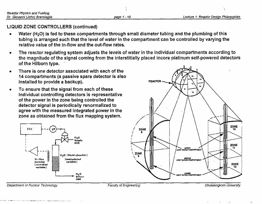
LIQUID ZONE CONTROLLERS (continued)
• Water (H20) is fed to these compartments through small diameter tubing and the plumbing of thistubing Js arranged such that the level of water in the compartment can be controlled by varying therelative value of the in-flow and the out-flow rates.
The reactor regulating system adjusts the levels of water in the individual compartments according tothe magnitUde of the signal coming from the interstitially placed incore platinum self-powered detectorsof the Hilborn type. .
There is one detector associated with each of the14 compartments (a passive spare detector is alsoinstalled to provide a backup).
To ensure that the signal from each of theseindividual controlling detectors is representativeof the power in the zone being controlled thedetector signal is periodically renormalized toagree with the measured integrated power in thezone as obtained from the flux mapping system.
Department ot Nuclear Technology Faculty of Engineerir:g Chulalongkom University

Reactor Physics and FuellingDr. Giovanni (.John) SrenciagUa page1-11 Lecture 1: Reactor Design Philosophies
FLUX MAPPING SYSTEM
• The flux mapping system consists of 102 self-powered vanadium flux detectors that are located in 26vertical interstitial assemblies. These detectors are typically about 30 cm long and hence provideessentially a point measurement of the thermal neutron flux.
• The software in the reactor regulating system is designed to convert these 102 point measurements to alocal flux distribution throughout the reactor. A typical arrangement of these flux detectors are shownbelow. The radial view is just one of the planes and is the one that contains the largest number ofdetectors.
I I I I 11:1, 1 I I
ii I II I IIi.' I
\ I I !' I I , I ' I
"
,;-
I
I I ' ";!.. I I
't-=-=-=-=-=-==--=h~'~'''=*=l=*='~'':::''$=~I+==+,. I I, f---------!-+--'----j---y-
IDepartment of Nuclear Technology Faculty of Engmeermg Chulalongkom University

Reactor PhYulcs and FuellingDr. Giovanni (Jo.·m) Brenciagfia page 1 - 12 ' Lecture 1: Reactor Design Philosophies
MECHANICAL CONTROL ABSORBERS
.~.l.,
. . ~-. ..
. ", '
J 0@@@
~@@@
S>@@@
o
@@@~@@@~@@@o
..... ~'.
W.' f'...... '
Used to extend the range of reactivity control in the negative direction beyond the liquid zones.
This system consists of four control absorber devices which physicaliy are the same as the shutoff roddevices, but they do not form part of the shutdown system.
The control absorbers are normally fully withdrawn from the reactor while the reactor is operatingunder normal steady state full power conditions. They are activated only when circumstances demandrapid reduction of the reactor power at a rate or over a range that cannot be accomplished by filling theliquid zone control system at the maximum possible rate.
Modes of insertion range from driving the rods in pairs to all four being dropped in by gravity followingrelease of an electromagnetic clutch ina manner similar to the operation of theshutoff rods. The mode of insertiondepends on the nature of the eventdemanding a rapid power reduction.
Since the power coefficient of reactivityis negative in the CANDU reactor apower reduction tends to increasereactivity and the reactivity worth of themechanical control absorber system ischosen so that the combined effect ofthis system and the zone controlsystem acting together will reducepower to a very low value withoutrequiring activation of either of theshutdown systems.
••
•
•
•
® Mechanical Control Absorber Rods
Department of Nuclear Technology Faculty of EngineerinQ Chulalongkom University
Reactor Physics and FuellingDr, Giovanni (John) Brenciaglia page 'i· 13 Lecture 1: Reactor Design Philosophies
ADJUSTER RODS
• To extend the range of the reactor regulating system in the positive direction beyond that available'fromthe zone control system, the reactor is designed to operate with a group of absorber rods fully insertedin the reactor during normal full power operation.
• This system of rods is called the adjuster rod system and in the CANDU 600 MWe reactor consists of21 stainless steel rods. If more positive reactivity is required than the zone control system can provide,these rods are withdrawn in groups as necessary.
• There are two circumstances where the reactivity decreases relative to the normal steady state powercondition to a degree that demands withdrawal of some or all of the adjuster rods to permit continuingoperation of the reactor.
(a) Fuelling machines being unavailable for a period of over one week after which the reactivitydecrease due to burnout of the fuel will exceed the range available in the zone control system.
(b) Transient increases in the concentration of xenon 135 following a reduction of reactor power.
• The adjuster rod system is nominally designed to have sufficient reactivity to compensate for theincrease in xenon 135 concentration that occurs within 30 minutes following a reactor shutdown. Sucha system provides capability to operate with fuelling machines unavailable for about a month.
Department of Nuclear Technology Faculty of Engineering Chulalcngkorn University

Reactor Phyo,vs and FuellingDr. Giovanni (John) Brenciaglia page 1 - 14
'ILecture 1: Reactor Design I-'nilosophies
:....... :
. :'i..:;··'
.f:'.... :'. '. '".,:....~:
• i~
" .
.....
......
0 0@ @ @ @ @ @
~ @ 0z@ @ @ @ @ @ -<>-
X
@ @ •~•@ @ @ @ @ @ m
~~
0 0
1/
;,~:t-.: ."..___...........-<1.-
.. ~~
. 'I~; ":~
ADJUSTER RODS (continued)
• Since the adjuster rods are normally fully inthe core their positions in the reactor and thedistribution of absorbing materials amongstthe rods are chosen to flatten the powerdistribution in an optimum manner so as tominimize the variation in the dischargeburnup of the fuel that is necessary toachieve the design power shape.
• The average to maximum channel powerratio in the reactor is a parameter which ischosen during the conceptual design stageand it determines the number of channelsthat are provided in the reactor to achieve agiven total output, without overrating anyonechannel.
• The 21 adjusters are grouped into seven banks, not allcomposed of an equal number of adjusters. The banksare chosen such that the reactivity worth of anyonebank does not exceed the range of the zone controlsystem. The reactivity worth of the complete system isabout 15 mk. The maximum reactivity change rateassociated with moving one bank of adjusters is < 0.1mk per second.
Department of Nuclear Technology Faculty of Engineering Chulalongkom University

ReacrorPhy~csandFuemng
Dr. Giovanni (John) Brenciaglia page 1· 15
iLecture 1: Reactor Design Philosophies
MODERATOR POISON
• Moderator poison is used to hold down excess reactivity during the initial fresh fuel conditions or'during.and following shutdown to compensate for lower than normal 135Xe levels due to decay.
• Boron is used under initial fuel conditions and gadolinium is used following shutdowns. The burnoutrate of gadolinium during operation at full power following an extended shutdown period is comparableto the xenon growth rate in terms of reactivity, hence the need to remove poison by ion exchange at a·fairly rapid and controlled rate is much less demanding.
• Poison can be added to the moderator for these purposes either automatically or manually.
• It should be noted that this system is completely independent of the very high speed liquid poisoninjection system which is used as a shutdown system.
• In the regulating system function the poison is inserted into the piping used to circulate the moderatorwhereas in the poison injection system, the poison is injected through nozzles that are installedhorizontally across the core, and a completely independent source of poison is used.
Department of Nuclear Technology Faculty of Engineering Chulalongkorn University

Reactor Physlos and FuellingDr. Giovanni (John) Brenciaglia page 1 - 16 Lecture 1: Reactor Design Philosophies
REACTOR SHUTDOWN SYSTEMS
• The CANDU·6 reactor is equipped with two physically independent shutdown systems.
• These systems are designed to be both functionally different and geometrically separate.
• The differences are achieved by using vertically oriented mechanical shutoff rods in the first systemand horizontally oriented liquid poison injection nozzles in the second system.
SHUTDOWN SYSTEM #1: SHUTOFF RODS
•
•
•
•
•
•
The shutoff (or shutdown) rods are tubes made upof a cadmium sheet sandwiched between twoconcentric steel cylinders.
The rods are inserted into perforated circularguide tubes which are permanently fixed in thecore.
The diameter of the rods (113 mm) is the maximumthat fits in the space between the calandria tubes.
The outermost four rods are about 4.4 m longwhile the rest are about 5.4 m long.
The rods are normally fully outside the core andare held in position by an electromagnetic clutch.
When a signal for shutdown is received the clutchreleases and the rods are initially accelerated by aspring and then fall by gravity into the core.
• VERTICAL FLUX DETECTOR UNIT (26)
@ ADJUSTER UNIT (21)
@ SHUTOFF UNIT (28)
I
o \]~;;? ... i';;.~~:,~:j~.,.:?:,.".
o ZONE CONTROL UNIT (6)
~ CONTROL ABSORBER UNIT (4)
e VIEWING PORT (2)
Department of Nuclear Technology Faculty of Engineering Chula/ongkom University

Reactor Physics and FuellingDr. Giovanni (John) Brenciaglia page 1- 17 Lecturp 1: Reactor Design Philosophies
SHUTDOWN SYSTEM #2: LIQUID POISON INJECTION SYSTEM
HELIUM COVEll GAS
------j"",J-
PRE~SVI\E OALANce LINt:
HEAVY WATEA MODERATOR
f10IS0N-MOOERATOR INTEflFACE
.. TO EXl-iAUST
H.". hELIUM SUI'f'LVTO 8 POISON tANKS
~
POISON TANK
GADOliNIUM NITRATEIN HEA'IV WAT~R
'M
'0
ISOLATION GAll VALVEINORMAlL Y OPEN!
30 3H 3J
ttEuUM VENT tiNES
QUle/(, OPENING VAL YES
'0
'"
flOATJNG BALL
fRQM ......-.....,HELIUM MAKHJP
H.P, HELIUM SUPPLY TANK
The alternative way of shutting down the reactor is through high speed injection of a solution ofgadolinium in heavy water into the calandria.
This is accomplishe~ by opening nigh speed valves which normally are closed and retain the solution athigh pressure in a vessel outside of the calandria.
When the valves are open the liquid poison is injected into the reactor moderator through sixhorizontally oriented nozzles that span the core.
The nozzles aredesigned to inject thepoison in four differentdirections in the form ofa large number ofindividual jets. Thisdisperses the poisonrapidly throughout alarge fraction of thecore.
•
•
•
•
Department of Nuclear Technology Faculty of Engineering Chulalongkom University
" ",-', ,~=...,,,,,,,"~., .• <, _",,',_ u".""~· '"'' .", ""'",, " .,._,,,

Reactor Physics and FuellingDr. Giovanni (John) 8renciagiia page 1- 18 Lecture 1: Reactor Design Philosophies
REGIONAL OVERPOWER PROTECTIVE SYSTEM
• To insure that localized overrating of the fuel does not occur an array of self-powered flux detectors ateprovided for application in the regional overpower protective system.
• A separate array of detectors is provided for each of the two shutdown systems.
• The detectors for the regional overpower protective system are "prompt" platinum detectors like t.hoseused for the spatial control system in the regulating system function.
-.
One of the diametral"planes" of detectors.
21tOI"" " U I' I) I " o • • , ..• , , ,1
!"}~ I, .....~",,~,
i W~1t-~
I ,..I .....
• , ,• -c0
• \, "G \
",•L
~
"• I ,0p
\ I0
\ I I I• \ I, 1/T
U
•..'--:. ~
-<
I ~~~:IH~~~
""0 H• T • T TT• I I I. I,""01 , • ""011 •• • •• I•
"v'~"1
• ""01 .."ell
" • •" "1'01'
TI • • ~
" rV~0!+r--.__ -IJ~~U\-----f--- ." ! v~.m II!J.
" .". '1,aav
" • •• v'O~t T
"• I --f,..,'O! ",=,t• • •,
I• v~101
• 1--, -. ..--" ..•• : e~ ••, U -_:: ~~
,... '0 • Vl,ll:TICAl ,~U\ Otn:c;o~S ...sn~'LIU uno •.., SO!I
MFO .. MOI'IIZO.... TAL'\,Ull O(TlC:':'CliII, "'SSl"'luU uuo IT S('IU
"
<
n
Department of Nuclear Technology Faculty of Engineering Chulalongkom University