Lect 13-1 Lect 13: 80486 and Pentium. Lect 13-2 80486 Microprocessor Family 80486 Microprocessor ...
26
Lect 13- 1 Lect 13: 80486 and Pentium
-
Upload
josephine-leonard -
Category
Documents
-
view
235 -
download
1
Transcript of Lect 13-1 Lect 13: 80486 and Pentium. Lect 13-2 80486 Microprocessor Family 80486 Microprocessor ...

Lect 13-1
Lect 13: 80486 and Pentium
Lect 13-2
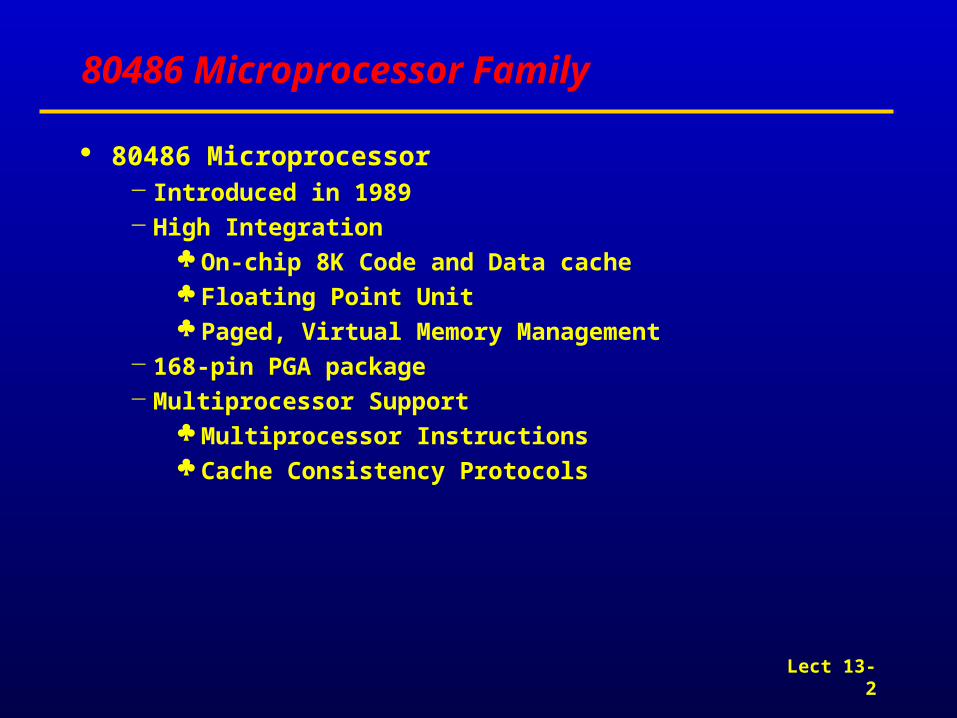
80486 Microprocessor Family
80486 Microprocessor Introduced in 1989 High Integration
On-chip 8K Code and Data cache Floating Point Unit Paged, Virtual Memory Management
168-pin PGA package Multiprocessor Support
Multiprocessor Instructions Cache Consistency Protocols

Lect 13-3
Internal Architecture of the 80486
Complex Reduced-Instruction-Set Computer (CRISC) RISC integer core

Lect 13-4
Real-Mode Software Model
the same as that shown for the 80386

Lect 13-5
Protected-Mode Software Architecture
AC: Alignment-Check flag When this bit is set, an alignment check is performed during all memory accesses at privilege level 3. If an unaligned access takes place, exception 17 occurs.

Lect 13-6
Control Registers
AM : alignment mask -- If this is switched to 0, the alignment check is masked out.
NE : Numeric Error CD : cache disable NW : not write-through WP : write protect
• PCD : page-level cache disable• PWT : page-level write transparent

Lect 13-7
System-Control Instruction Set
+ a flush bus cycle
+ a write-back bus cycle

Lect 13-8
Page Directory and Page Table Entries

Lect 13-9
Hardware Architecture of the 80486

Lect 13-10
Signal Interfaces
Pseudo-lock

Lect 13-11
On-Chip Cache of the 80486SX

Lect 13-12
Pentium Processor
Pentium Processor 32-bit Microprocessor
32-bit addressing 64-bit Data Bus
Superscalar architecture Two pipelined integer units Capable of under one clock per instruction Pipelined Floating Point Unit
Separate Code and Data Caches 8K Code, 8K Write Back Data 2-way 32-byte line size MESI cache consistency protocol
Advance Design Features Branch Prediction
237-pin PGA

Lect 13-13
Internal Architecture of the Pentium Processors

Lect 13-14
Pentium Processor
Pipeline and Instruction Flow 5 stage pipeline
PF : prefetch
D1 : Instruction decode
D2 : Address Generation
EX : Execute -ALU and Cache Access
WB : Write Back
Intel 486 Pentium
I1 I3I2 I4
I1 I3I2 I4
I1 I3I2 I4
I1 I3I2 I4
I1 I3I2 I4
PF
D1
D2
EX
WB
I1
I2
I5
I6
I7
I8
I3
I4
I1
I2
I5
I6
I7
I8
I3
I4
I1
I2
I5
I6
I7
I8
I3
I4
I1
I2
I5
I6
I7
I8
I3
I4
I1
I2
I5
I6
I7
I8
I3
I4
PF
D1
D2
EX
WB

Lect 13-15
Pentium Processor
“U”, “V” pipes - “pairing” U : any instruction V : ‘simple instructions” as defined in the ‘Pairing” rules
PF : instructions on chip cache or memory -> prefetch buffers
prefetch buffers - two independent pairs of line size(32 bytes)
D1 : two parallel decoders
D2 : address generation for operand fetch
EX : ALU operations and data cache access
WB : modify processor state ; complete execution

Lect 13-16
Branch Prediction
Branch Prediction Branch Target Buffer The processor accesses the BTB with the address of the instructi
on in the D1 stage
example)
inner_loop : mov byte ptr flag[edx], al PF D1 D2 EX WB
add edx, ecx PF D1 D2 EX WB
cmp edx, FALSE PF D1 D2 EX WB
jle inner_loop PF
486 : 6 clocks
Pentium : 2 clocks with branch prediction

Lect 13-17
EFLAGS

Lect 13-18
Control Registers of the Pentium Processor

Lect 13-19
Enhancements to the Instruction Set

Lect 13-20
Hardware Architecture

Lect 13-21
Memory Subsystem

Lect 13-22
Organization of the DRAM Array

Lect 13-23
RAS/CAS address MUX

Lect 13-24
Data Bus Transceiver Circuitry

Lect 13-25
On-Chip Cache

Lect 13-26
On-chip cache operating mode