Learning Objectives - g w · PDF file · 2012-02-06Learning Objectives After...
15
Learning Objectives After studying this chapter, you will be able to: Identify the five basic welding joints. Identify and describe the various welds that may be used in each welding joint. Label the parts or areas of a grooved butt weld and a fillet weld. Locate and apply required weld and joint information from an AWS welding symbol. List and describe the four welding positions. The field of welding uses standardized termi- nology to describe the various welding joints and welding positions that every welder must know. This chapter will introduce and explain many essential welding vocabulary terms. Also, when a welder is given a mechanical drawing, he or she needs to be able to understand the type and location of the welds to be made by reading the welding symbols. This chapter will also explain how to read and understand the meaning of AWS welding symbols. 3.1 Basic Weld Joints A weld joint refers to how the parts to be joined are assembled prior to welding. There are five basic types of joints used in welding: butt, lap, corner, T-, and edge. See Figure 3-1. The metal to be joined is called the base metal. If the part to be welded is not metal, it is called base mate- rial. It is also known as the workpiece or work. The edges of the base metal are often machined, sheared, gouged, flame cut, or bent to prepare them for welding. Weld joint design and metal thickness usually deter- mine how the joint is prepared. Generally, the weld joint design is determined by an engineer. 3.1.1 Butt Joint Butt joints are used when parts are joined edge- to-edge. Common examples of butt joints are the deck plates on a ship or the pipes of an oil pipeline. Both are assembled end-to-end. There are a variety of butt joint configurations, depending on how the ends of the pieces being joined are prepared. For quality welds to be produced on butt joints, the edges of the base metal often require special preparation before welding. 1 This sample chapter is for review purposes only. Copyright © The Goodheart-Willcox Co., Inc. All rights reserved.
Transcript of Learning Objectives - g w · PDF file · 2012-02-06Learning Objectives After...

Learning ObjectivesAfter studying this chapter, you will be able to:
Identify the fi ve basic welding joints.
Identify and describe the various welds that may be used in each welding joint.
Label the parts or areas of a grooved butt weld and a fi llet weld.
Locate and apply required weld and joint information from an AWS welding symbol.
List and describe the four welding positions.
The fi eld of welding uses standardized termi-nology to describe the various welding joints and welding positions that every welder must know. This chapter will introduce and explain many essential welding vocabulary terms. Also, when a welder is given a mechanical drawing, he or she needs to be able to understand the type and location of the welds to be made by reading the welding symbols. This chapter will also explain how to read and understand the meaning of AWS welding symbols.
3.1 Basic Weld JointsA weld joint refers to how the parts to be joined
are assembled prior to welding. There are fi ve basic types of joints used in welding: butt, lap, corner, T-, and edge. See Figure 3-1.
The metal to be joined is called the base metal. If the part to be welded is not metal, it is called base mate-rial. It is also known as the workpiece or work. The edges of the base metal are often machined, sheared, gouged, fl ame cut, or bent to prepare them for welding. Weld joint design and metal thickness usually deter-mine how the joint is prepared. Generally, the weld joint design is determined by an engineer.
3.1.1 Butt JointButt joints are used when parts are joined edge-
to-edge. Common examples of butt joints are the deck plates on a ship or the pipes of an oil pipeline. Both are assembled end-to-end. There are a variety of butt joint confi gurations, depending on how the ends of the pieces being joined are prepared. For quality welds to be produced on butt joints, the edges of the base metal often require special preparation before welding.
1
This sample chapter is for review purposes only. Copyright © The Goodheart-Willcox Co., Inc. All rights reserved.

2 Modern Welding
Figure 3-1. Basic welding joint designs. Note that there are only fi ve basic joints, but that many types of welds can be placed on each type of joint. (AWS A3.0:2010, Figure 1, Joint Types, reproduced with permission from the American Welding Society, Miami, Fl.))
Joint & welding symbol
Edge ofbase metal/plastic
Surface ofbase metal/plastic
Joint
Joint
Applicable Welds
Bevel-groove U-grooveFlare-bevel-groove V-grooveFlare-V-groove EdgeJ-groove SeamSquare-groove
Applicable Welds
Fillet SlotBevel-Groove SpotFlare-Bevel-Groove SeamJ-Groove ProjectionPlug Braze
Joint
Joint
Joint
Joint
Applicable WeldsBevel-groove U-grooveFlare-bevel-groove V-grooveFlare-V-groove Edge-flangeJ-groove BrazeSquare-groove
Applicable Welds
Applicable Welds
Fillet SlotBevel-groove SpotFlare-bevel-groove SeamJ-groove ProjectionSquare-groove BrazePlug
Fillet V-grooveBevel-groove PlugFlare-bevel-groove SlotFlare-V-groove SpotJ-groove SeamSquare-groove ProjectionU-groove Braze
Corner Joint
Butt Joint T-Joint
Edge Joint Lap Joint
Chapter 3 Welding Joints, Positions, and Symbols 3
Edge preparation refers to how the edges of the joint are shaped prior to welding. If the base metal is thin, the edges may just be squared without addi-tional machining or cutting. The edges of thin metal may also be bent to form fl are-groove or edge-fl ange joints, as shown in Figure 3-2.
Generally, when base metal over 3/16″ (4.8mm) thick is used, edges are beveled by machining or fl ame cutting. Edge preparation is required to allow the weld to penetrate to the required depth. Thick base metal may be machined, gouged, or fl ame cut along the upper or lower edges of the joint, or both, to form a double-bevel, V-, J-, or U-groove.
A butt joint can be prepared using any of the edge preparations shown in Figure 3-2. A groove weld is made by fusing molten fi ller metal into a butt joint that has been set up in a groove formation. These groove formations include a single-square groove; a single or double-bevel, V-, J-, or U-groove; or a fl ared groove, which forms a groove where the edge is bent.
A welder should know the names of the various parts of a groove joint, as shown in Figure 3-3A. The groove face is the surface formed on the edge of the base metal after it has been machined or fl ame cut. The total angle formed between the groove face on one piece and the groove face on the other piece is the groove angle. The bevel angle is the angle between the bevel of the joint and a plane perpendicular to the surface of the base material. The weld root is the point where the weld intersects the base metal surface near the bottom of the joint. The distance from the weld root to the point where the bevel angle begins is the
root face. The root opening is the distance between the two pieces at the root of the weld.
Figure 3-3B shows a cross section of a completed weld. The weld face is the outer surface of the weld
Figure 3-2. Students should become familiar with the various methods of preparing the edges of a butt joint. Double grooves are used on thick metal that is welded from both sides. The base metal is bent to form the bottom three joints.
Single-square-groove weld
Single-V-groove
Double-J-groove
Flare-bevel-groove Flare-V-groove weld Edge weld on a flanged butt joint
Double-U-grooveSingle-U-groove
Single-J-grooveDouble-V-groove
Single-bevel-groove Double-bevel-groove
Figure 3-3. Approved terms used to describe the parts of a groove-type butt joint. A—The groove angle should be just large enough to allow the torch or electrode to reach the root opening. B—Terms used to describe a completed groove weld.
Electrode
Groove angle
Bevelangle
Root face
Weld rootRoot
opening
Facereinforcement
Root reinforcement
Weldface
Weldtoe
Weldtoe
A
B
Groove face
Joint penetrationor weld size
This sample chapter is for review purposes only. Copyright © The Goodheart-Willcox Co., Inc. All rights reserved.

4 Modern Welding
bead on the side the weld was made. Face reinforcement is the distance from the top of the weld face to the surface of the base metal. The weld toe is the point where the weld bead contacts the base metal surface. It occurs twice on each weld bead. Root reinforcement is the distance that the penetration projects from the root side of the joint. Joint penetration or weld size is the depth that a weld extends into the joint from the surface.
3.1.2 Lap JointA lap joint is formed by two overlapping pieces
of base metal. The top surface of one piece is in contact with the bottom surface of the other, as shown in Figure 3-1. Special edge preparation is not required.
3.1.3 Corner JointA corner joint is formed by placing two pieces of
base metal perpendicular or at an angle to one another so that the edge of one piece of base metal intersects the surface of the other piece near its outer edge. At
least one edge of the two pieces is exposed, as illus-trated in Figure 3-4. The pieces may be joined at any angle, but they are commonly welded at a 90° angle. Corner joints may be welded as inside corners, outside corners, or a combination of both. Inside corner joints are welded along the inside of the intersection of the two pieces. Outside corner joints are welded along the outside edge of the joint. The edges may be square, beveled, J-grooved, fl ared, or edge-fl anged. See Figure 3-4.
3.1.4 T-JointA T-joint is formed by two pieces of base metal
that are at an angle of approximately 90° to one another. The main difference between a corner joint and T-joint is that a corner joint is formed along the edges of both pieces, while a T-joint is formed at the edge of one piece and away from the edge of the second piece. The edges of the base metal may be prepared as a square, bevel-grooved, J-grooved, or fl are-bevel-groove joint, as shown in Figure 3-5. Both edges of the base metal may be prepared to form a double-bevel-groove joint.
Fillet weld on aninside corner
(no preparation)
Square-groove weldon an outside corner
(no preparation)
V-grooveoutside corner
Bevel-grooveoutside corner
J-grooveinside corner
J-grooveoutside corner
U-grooveoutside corner
Bevel-grooveinside corner
Single-flare-bevel-grooveweld on an inside corner
Single-flare-bevel grooveweld on an outside corner
Edge weld on aflanged corner
Figure 3-4. Various methods of preparing the edges of corner joints. Three of these joints require the base metal to be bent for proper formation. The fi rst two corner joints depict no special preparation of the edges.
Chapter 3 Welding Joints, Positions, and Symbols 5
3.1.5 Edge JointAn edge joint is formed when the surfaces of two
pieces are in contact and their edges are fl ush (even). The pieces are joined by welding along at least one of the fl ush edges. Figure 3-6 shows the edge prepara-tion for various edge joints.
3.1.6 Flange JointA fl ange joint is formed when the edge of one or
more pieces of the joint is bent to form a fl ange. The edges are aligned and a weld is placed along the speci-fi ed edges. Figures 3-2, 3-4, and 3-6 show examples of fl ange joints.
3.1.7 Flare-Groove JointFlare-groove joints are formed when the fl anged
edges of one or both pieces are placed together to form a single-fl are-bevel or double-fl are-V-groove. The weld is placed in the bevel or V-groove, as shown in Figures 3-2, 3-4, and 3-5.
3.2 Types of WeldsA weld is a fused joint between two or more pieces
of metal or nonmetal. Welds are created by applying heat until the materials melt, fl ow together, and are cooled to form a single piece. This can be done with or without
Square-groove Bevel-groove Double-bevel-groove
Flare-bevel-grooveJ-groove
Figure 3-5. Various methods of T-joint edge preparation.
Square-groove Bevel-groove V-groove J-groove U-groove
Edge-flange weld
Figure 3-6. Various edge preparations for edge-type joints.
This sample chapter is for review purposes only. Copyright © The Goodheart-Willcox Co., Inc. All rights reserved.

6 Modern Welding
the addition of a fi ller material and with or without the use of pressure. See Figure 3-7. Welding is the process of making a weld on a joint. Fillet welds are made at the intersection of a surface and an edge or in a corner where two surfaces meet. Fillet welds are generally triangular in shape, as shown in Figure 3-8, and are placed into lap, inside corner, and T-joints. A groove weld is a weld made in a groove or gap created between two pieces of metal. Groove welds can be used on all types of weld joints.
When the edges of thicker metal are machined or fl ame cut, metal is removed from the pieces. Filler mate-rial must be added to replace the metal that is removed. The addition of fi ller metal ensures that the completed weld joint is as thick and as strong as the base metal. Edge, fl ange, or fl are-groove joints for thin metal may be welded without the addition of fi ller material. Figures 3-2, 3-4, 3-5, and 3-6 show edge, fl ange, and fl are-groove joints.
The parts and dimensions for fi llet welds are the same for lap, inside corner, and T-joints. Refer to Figure 3-8. The weld face is the outer surface of the weld bead. As previously mentioned, the weld toe is the point where the weld face touches the surface of the base metal. A fi llet weld is made up of three primary dimensions. The fi llet weld size is the length of one side. The leg is the shortest distance from the toe to the surface of the other piece of base metal. The effective throat is the minimum distance from the weld face to the root of the weld without any convexity.
Figure 3-8 shows two fi llet welds with the same leg dimensions, but different sizes. The size of the weld with a concave bead, Figure 3-8A, is smaller than the size of the weld with a convex bead, Figure 3-8B. A fi llet weld with a convex bead is stronger than one with a concave bead because of the additional fi ller metal.
3.2.1 Weld Beads and Weld PassesA weld bead is one weld pass of fi ller metal that
is added to a weld joint. A weld pass occurs each time a welder lays one weld bead across a weld joint. Only one weld bead or weld pass is required for fusing thin base metal, Figure 3-9A. If the metal is thick, more
Figure 3-7. A square-groove weld for an edge joint is in progress. The weld pool extends to the outer edges of the base metal. Filler metal may not be required on thin pieces of base metal.
Torch tipWeld bead
Weld pool
Tack weld
Figure 3-8. Look at the parts of these fi llet welds. Weld A is concave. Its weld size is smaller than Weld B, which is a convex weld. Notice that the leg sizes in Weld A and B are the same, but the weld size is larger with a straight or slightly convex bead.
A B
LegSize
Leg
SizeEffective
throat
Effectivethroat
Leg and size
Leg andsize
Weld face
Toe of weld
Toe of weld
1/8" (3.2mm)
1/2" (13mm)
A
B
Figure 3-9. A—On this single-pass weld on thin base metal, notice the build-up of weld metal and complete penetration. B—On this multiple-pass weld on thick base metal, the edges have been prepared to form a V-groove joint. Notice the root opening required. Three beads were used, with each bead measuring less than 1/4″ (6.4mm) thick. A weaving bead may be used for the wider, upper bead.
Chapter 3 Welding Joints, Positions, and Symbols 7
than one weld pass is required to make a strong joint with complete penetration. See Figure 3-9B. The fi rst weld pass is the root pass. The second or intermediate weld pass is called a fi ller pass. The fi nal weld pass is the cover pass. See Figure 3-10A. On very thick metal (over 1/2″ or 13mm), multiple fi ller passes are required to fi ll deep and wide joints, Figure 3-10B. Generally, a weld bead should not be thicker than 1/4″ (6.4mm). A weld bead may be made as a stringer bead or a weave bead.
3.2.2 Stringer BeadA stringer bead is used when a standard bead
width is acceptable. Stringer beads are made by moving the torch or electrode along the weld without any side-to-side motion. See Figure 3-11A. Multiple stringer beads need to be made to fi ll a V-groove butt weld on very thick metal as shown in Figure 3-10B.
3.2.3 Weave BeadA weave bead is used to create a wider weld pool.
A weave bead is formed by moving the torch or elec-trode from side-to-side as the weld pass progresses along the weld joint. See Figure 3-11B.
Various torch or electrode movement patterns can be used when making a weave bead. The crescent motion, shown in Figure 3-11C, is one of the most popular patterns.
3.3 Joint GeometryThe American Welding Society defi nes joint
geometry as “the shape and dimensions of a (weld) joint, in cross section, prior to welding.” Joint geom-etry is generally determined by a welding engineer or designer. The assembly design and the dimensions of a joint depend on the metal thickness and shape and on the load requirements of the parts. The parts are prepared to ensure that the weld will have adequate penetration. The joint geometry design also provides space for the welder to reach near the bottom of the weld joint with the torch or electrode.
Figure 3-10. Multiple-pass welds. A—Three weld passes are used in this example. The fi rst two passes are stringer beads. The cover pass is a weave bead. B—Twenty stringer beads were used in this weld on very thick metal. Each bead is no thicker than 1/4″ (6.4mm).
Weldpool
Torch tip Cover pass(3rd bead)
Directionof travel
Filler pass(2nd pass)
Root pass(1st bead)
A
B
Figure 3-11. Comparison of stringer and weave beads. A—A stringer bead is in progress on a square-groove butt joint. The bead width is two to three times the metal thickness. B—A weave bead is in progress. The torch tip and weld pool are moved from side-to-side in the direction of the arrow. C—A suggested motion for creating a weave bead. The bead width is seldom greater than 3/4″–1″ (19mm–25mm).
A
B
C
Direction of travel
Weld pool Torch tip
Direction of motion
This sample chapter is for review purposes only. Copyright © The Goodheart-Willcox Co., Inc. All rights reserved.

8 Modern Welding
3.3.1 PreparationThe edges of thick metal are prepared for welding
by fl ame cutting, gouging, or machining. Preparation allows the weld to penetrate as deep as required by the engineer or weld designer. A groove joint allows the welder to reach the bottom of the weld joint. The groove angle must be large enough to allow the torch tip or electrode to reach near the bottom of the joint. However, if the groove angle is too large, fi ller metal and the welder’s time are wasted. This increases the cost of making a weld. See Figure 3-12A. A properly designed J-groove or U-groove joint also decreases the groove dimensions while allowing adequate space for welding. See Figure 3-12B.
3.3.2 Joint AlignmentThe alignment of a joint before welding is very
important. In the shop, the alignment of the weld joint is often referred to as “fi t-up.” A ragged edge or an edge that is not cut straight is hard to weld. See Figure 3-13. Edges to be welded must be straight and cut to exact size.
Parts of a weldment should be properly aligned and held in position during the welding operation. Tack welding is usually adequate to hold parts during welding. A tack weld is a small weld used to hold
pieces in alignment. Parts may also be held mechani-cally during the welding operation because the metal expands, bends, and changes shape when heated. Clamps or other devices, such as jigs and fi xtures, are used to hold weldments during welding. See Figure 3-14.
Figure 3-12. Compare the 70° and 90° groove angles. A—A 70° groove angle is cheaper to weld than a 90° groove angle. The shaded area represents an unnecessary cost in fi ller metal and welder time. B—Look at the U-groove joint. The root of the weld can be reached easily. Little fi ller metal and welder time are wasted.
90°
70°
A
B
Figure 3-13. Poorly prepared base metal edges. The edges in A are ragged. One edge in B is not cut straight, which changes the width of the joint. Both joints would be diffi cult to weld.
A
B
Figure 3-14. These various clamps are used to position and hold parts to be welded. (Bessey Tools North America)
Chapter 3 Welding Joints, Positions, and Symbols 9
3.3.3 PenetrationA completed weld joint must be at least as strong
as the base metal. The weld must penetrate deeply into the base metal to be strong. Penetration is the depth of fusion of the weld below the surface. Total (100%) penetration occurs when a weld penetrates through the entire thickness of the base metal. Generally, total penetration is required only on a butt joint. The edges of thick metal may need to be machined or fl ame cut to achieve 100% penetration. Thick metal also may have to be welded from both sides of the joint.
3.4 Welding PositionsWelders often must weld in a variety of positions.
Welds may be made in the fl at, horizontal, vertical, or overhead welding positions. See Figure 3-15. On welding drawings, these positions are often abbreviated in the tail of the welding symbol as F, H, V, and O. The Amer-ican Welding Society refers to welding positions with a number and letter combination. Groove joints in the fl at, horizontal, vertical, and overhead positions are referred to as 1G, 2G, 3G, and 4G, respectively. Fillet joints in the fl at, horizontal, vertical, and overhead position are desig-nated as 1F, 2F, 3F, and 4F, respectively.
Welding positions are determined by the posi-tions of the weld axis and weld face. Figure 3-16 shows the weld axis and weld face. The weld axis is an imag-inary line running lengthwise through the center of a completed weld. The weld face is the exposed surface of a completed weld on the side on which the welding was done.
Figure 3-15. Each of the fi ve basic weld joints may be made in four different welding positions.
Butt Joint
1G 1G 1F 1F 1G
2G 2G 2F 2F 2G
3G 3G 3F 3F 3G
4G 4G 4F 4F 4G
Fla
tH
ori
zon
tal
Ver
tica
lO
verh
ead
Corner Joint T-Joint Lap Joint Edge Joint
Figure 3-16. The weld axis is an imaginary line running lengthwise through the center of the weld. The weld face is the exposed surface of the fi nished bead.
Weld face
Weld axis
This sample chapter is for review purposes only. Copyright © The Goodheart-Willcox Co., Inc. All rights reserved.

10 Modern Welding
3.4.1 Flat (1G) Welding PositionWelds made on a groove joint in the fl at (1G)
welding position must meet these conditions: ● The weld axis must be within 15° of
horizontal. See Figure 3-17. ● The weld face is within 30° of horizontal.
● The weld is made from the upper side of the joint.
3.4.2 Horizontal (2G) Welding Position
Groove welds made in the horizontal (2G) welding position must meet these conditions:
● The weld axis must be within 15° of horizontal.
● The weld face must be between 80°–150° or 210°–280°. See Figure 3-18. Angles are measured clockwise with 0° at the bottom.
3.4.3 Vertical (3G) Welding PositionA weld on a groove joint in the vertical (3G) welding
position must meet either of these sets of conditions:Condition A
● The weld axis is 80°–90° from horizontal.● The weld face is between 0°–360° from
horizontal. See Figure 3-19A.Condition B
● The weld axis is 15°–80° from horizontal. ● The weld face is within 80°–280° from
horizontal. ● The weld is made from the upper side of the
joint. See Figure 3-19B.
3.4.4 Overhead (4G) Welding PositionWelds made on groove joints in the overhead (4G)
welding position are made under these conditions: ● The weld axis is between 0°–80°.
Figure 3-17. These are the specifi cations for AWS 1G or fl at groove welding position. A—The weld axis must be within 15° of horizontal. B and C—The weld face must be within 30° of horizontal.
15° up fromhorizontal
to15° down
Weldface
Horizontal
Weld axis Horizontal
Weld axis
0°–30°
Weldaxis
Weldface
0°–30°
Weld axis
Horizontal
Weldface
A
B
C
Weldaxis
Chapter 3 Welding Joints, Positions, and Symbols 11
● The weld face is between 0°–80° or 280°–360°. ● The weld is made from the lower side of the
joint. See Figure 3-20.
3.5 The Welding SymbolThe welding symbol described on the following
pages was developed by the American National Stan-dards Institute (ANSI) and the American Welding Society (AWS). It is described in detail in the publi-cation ANSI/AWS A2.4, Standard Symbols for Welding, Brazing, and Nondestructive Examination.
The entire symbol, as shown in Figure 3-21 with all of its numbers and other symbols, is called the welding symbol. Welding symbols are used on draw-ings of parts and assemblies which are joined together by welding. A welding symbol may appear in any view on the drawing. Whenever two or more pieces are joined by welding, the assembled item is called a weldment. When the pieces of a weldment are assem-bled, the lines along which their edges and surfaces come in contact are called joints.
Figure 3-18. These are the specifi cations for the AWS 2G or horizontal groove welding position. A—The weld axis must be within 15° of horizontal. B—An end view (View B) with the weld shown in blue. The weld face must be within 80°–150° or 210°–280°. All angles are measured clockwise with 0° at the bottom.
80°
80°−150°210°−280°
150°
280°
210°
0°View B-BB
A
View B-B15° down
15° up
Horizontal
Weld face
Weld face
Weld axis
0°
Figure 3-19. These are the specifi cations for the AWS 3G or vertical groove welding position. A vertical weld must meet either of the following sets of conditions. A—The weld axis must be between 80° and 90° from horizontal. Look at View A. The weld face may be rotated from 0°–360°. B—The weld axis is 15°–80° from horizontal. Look at View B. The weld face must be within 80°–280°.
A View A-A
0°−360°View A-A
Vertical
Weldface
Weldaxis
Weldaxis
80°−90°
Weld axis
Weldface
View B-B
Horizontal
Weldaxis
Weld face
80° 280°
0°
80°–280°
B
15°–80°
View B-B
This sample chapter is for review purposes only. Copyright © The Goodheart-Willcox Co., Inc. All rights reserved.

12 Modern Welding
The drawing of a weldment seldom shows how the edges are to be prepared or how the completed weld appears. The drawing shows only how the parts come together and what type of joint they will form. Occasionally, when an unusual or very complex weld joint is to be made, a “detail” drawing of the joint may be drawn with the joint preparation and weld shape shown and dimensioned. Refer to Figure 3-1 for the types of welded joints and the types of welds used on the various joints.
A complete welding symbol contains all the information about a welded joint. The welding symbol may appear in any view of the drawing. A welding symbol applies to only one joint and applies to that joint only until it changes direction. There are a few exceptions to this rule—they will be discussed later in this chapter. Some of the following information is given to the welder on the welding symbol:
● How to prepare the edges of the base metal prior to welding.
● What welding process to use. ● What type of weld to make. ● Where to place the weld. ● The size of the weld. ● The shape of the weld face. ● How to fi nish the weld surface after welding
is completed.Much more information regarding the weld is
also given on the welding symbol. Dimensions on a welding symbol may be in SI Metric units or US Customary units of measurement.
Part of the complete welding symbol is the weld symbol, which shows what type of weld is to be placed in a joint. See Figure 3-21 for the position of
the weld symbol within the overall welding symbol. Figure 3-22 shows the weld symbols used on an ANSI/AWS welding symbol.
Information given in each part or area of the welding symbol will be explained in later paragraphs. A number of weld drawings, with their corresponding welding symbols, will be shown to illustrate the infor-mation given in the various areas of the complete welding symbol. The edges of the weld joint, as they would be prepared and fi tted up prior to welding, will be shown using hidden lines. A completed weld for the welding symbol will also be shown.
3.5.1 The Reference Line, Arrowhead, and Tail
The reference line, shown in Figure 3-23, is always drawn as a horizontal line. It is placed on the drawing near the joint to be welded. All information to be given on the welding symbol is shown either above or below this horizontal reference line. Infor-mation given on a welding symbol is always shown in the same location, as indicated in Figure 3-21. The information is read from left to right whether it is above or below the reference line.
The arrow may be drawn from either end of the reference line. The arrow always touches the line that represents the welded joint.
The tail is used only when necessary. It may be used to give information on specifi cations, the welding process used, or other details required but not shown on the welding symbol. A number (such as 1, 2, or 3) may be used in the tail to refer the user to a note elsewhere on the drawing. A company may use
Figure 3-20. These are the specifi cations for the AWS 4G or overhead groove welding position. The weld axis must be between 0° and 80°. Look at View A. The weld face must be between 0° and 80° or 280° and 360°. The weld is made from the lower side of the base metal.
Weld axis
80°−280°
0°−80°
80°
0°View A-A
0°
Weld face
Weld axis
View A-A
Weld face
Chapter 3 Welding Joints, Positions, and Symbols 13
its own number or letter codes in the tail to indicate the welding process, procedure, fi nishing method, or company specifi cation.
If no tail is used, a note such as “Unless otherwise specifi ed, all welds will be made in accordance with Specifi cation No. XXXX,” will be displayed some-where on the drawing.
3.5.2 Weld SymbolsThe weld symbol shown on the complete welding
symbol indicates the type of weld to be made on a weld joint. It is a miniature drawing that shows how the edge or edges of the joint are prepared before welding.
Figure 3-24 illustrates how some of the weld symbols shown in Figure 3-22 are used on a welding symbol. Fillet, bevel-groove, and J-groove welding symbols are always drawn so the vertical line is to the left of the non-vertical lines. See Figures 3-22 and 3-24.
3.5.3 The Arrow Side and Other SideOn the drawing of a welded part, the arrow of
the welding symbol touches the line to be welded. The metal has two sides. The side of the metal which the arrow touches is always the arrow side. The opposite surface from the arrow is called the other side.
Because of the joint position on many weldments, there is no inside or outside, top or bottom, left or right. To simplify identifying the location of the weld, the terms arrow side and other side are used. On the welding symbol, the arrow side weld information is always shown below the reference line. The other side weld information is always shown above the reference line.
It is not always possible to place the welding symbol on the side to be welded. The drawing is some-times too crowded and complicated. See Figure 3-25 for examples of the use of the arrow side and other side on the welding symbol.
Figure 3-21. Specifi c locations have been assigned on the welding symbol for various information and sizes. (AWS A2.4:2012, Figure 3, Standard Location of the Elements of a Welding Symbol, reproduced with permission from the American Welding Society, Miami, Fl).
R
L-PS(E)
(N)
AF
T
Sid
es
Oth
er s
ide
Arr
ow s
ide
Bot
h
Finish symbol
Contour symbol
Weld symbol
Groove weld size
Depth of bevel; size orstrength for certain welds
Specification,process, orother reference
Tail (may be omittedwhen referenceis not used)
Elements in this area remain as shownwhen tail and arrow are reversed
Weld symbols shall be containedwithin the length of the reference line
Number of spot, seam, stud, plug, slot, or projection welds
Reference line
Arrow connectingreference line to arrow side memberof joint or arrowside of joint
Weld-all-aroundsymbol
Field weldsymbol
Pitch (center-to-center spacing)of welds
Length of weld
Root opening; depth of fillingfor plug and slot welds
Groove angle; included angleof countersink for plug welds
ANSI/AWS Standard Welding Symbols
This sample chapter is for review purposes only. Copyright © The Goodheart-Willcox Co., Inc. All rights reserved.

14 Modern Welding
Groove
Square Scarf V Bevel U J Flare-V Flare-bevel
FilletPlug
orslot
StudSpot
orprojection
SeamBack
orbacking
Surfacing Edge
Weld allaround
Field weldMelt
through
Consumableinsert
(square)
Backingor spacer
(rectangle)Flushor flat
Backing
Spacer
Convex
Contour
Concave
Weld Symbols and Supplementary Symbols
Plug
Slot
Figure 3-22. Weld symbols and supplementary symbols. These may be part of the complete welding symbol. (AWS A2.4:2012, Figure 1, Weld Symbols, and Figure 2, Supplimentary Symbols, reproduced with permission from the American Welding Society, Miami, Fl)
Figure 3-23. Reference line, arrow, weld symbol and tail of the complete welding symbol. A—Drawing and welding symbol. B—The edge shape of the metal. C—Completed weld.
TailReference
line
Weld symbol
Arrow
A
B
C
Chapter 3 Welding Joints, Positions, and Symbols 15
3.5.4 Root Opening and Groove Angle
The root opening is the space between the pieces at the bottom or root of the joint. Prior to welding, the two pieces to be welded are spaced apart the distance indicated by the root opening. This root opening may be specifi ed on the drawing in metric units, in frac-tions of an inch, or as a single-place decimal of an
inch. The root opening size appears inside the weld symbol on the complete welding symbol.
The included angle or total angle of a groove weld is shown beyond the weld symbol. See Figure 3-26. When preparing the edges for a V-groove welding, half the groove angle is cut on each piece. When placed together, the combined angles will total the angle shown.
Figure 3-24. Comparing welding symbols and actual welds. Phantom lines are not shown on a weld symbol. They are used here, however, to illustrate that the weld symbol is a miniature drawing of the edge shape and the type of weld used. The vertical line in the bevel-groove and fi llet weld symbols is always drawn to the left.
Comparison of Welding Symbols and Actual Welds
Completed T-joint weld
Symbol for T-joint withfillet welds both sides
Completedbevel-groove
butt joint
Symbol forbevel-groove
butt joint
Completedsquare-groove
butt weld
Symbol forsquare-groove
butt joint
Figure 3-25. The side of the metal that the arrow touches is the arrow side. Placement of the weld symbol on the welding symbol determines whether the weld will be made on the arrow side or on the other side from the arrow.
Placement of Weld Symbols
Otherside
Other side
Otherside
Otherside
Otherside
Arrowside
Arrowside
Arrowside
Arrowside
Arrowside
Arrowside
A B C
Other side
This sample chapter is for review purposes only. Copyright © The Goodheart-Willcox Co., Inc. All rights reserved.

16 Modern Welding
When a bevel-groove or J-groove weld is used, only one piece of metal is cut or ground. The arrow at the end of the welding symbol is bent along its length to the left or right to point to the piece that is to be cut or ground. See Figure 3-26, view D, and Figure 3-27, view A.
3.5.5 Contour and Finish SymbolsThe shape or contour of the completed weld bead
is shown on the welding symbol as a straight or curved line between the weld symbol and the fi nish symbol. The straight contour line indicates that the weld bead is to be made as fl at as possible. The curved contour line indicates a normal convex or concave weld bead. See Figure 3-27.
If the weld is not to remain in an “as welded” condition, a fi nish symbol is used on the welding symbol. See Figure 3-27. The fi nish symbol indicates the method of fi nishing. A surface texture or degree of fi nishing may also be added if required. If all welds are to be fi nished in the same manner, a note on the drawing may indicate the fi nish used. Users of the fi nish symbol may create their own fi nish symbols.
The American Welding Society lists the following fi nish symbols:
C: ChippingG: GrindingM: MachiningR: RollingH: Hammering
3.5.6 Depth of Bevel, Size or Strength, and Groove Weld Size
The “S” position on the welding symbol indicates the depth of bevel or the depth of preparation for a groove-type joint. Information in the “S” position may also indicate the size or strength of certain welds.
The size of a fi llet weld is the length of the legs (sides) of the triangle that can be drawn inside the cross section of the fi nished weld, as shown in Figure 3-28. The lengths of the legs on a typical fi llet weld are equal, so only one dimension is given in the “S” area of the welding symbol. If the fi llet weld has unequal legs, the size of each leg is shown in the weld symbol. The weld shape of this fi llet weld may be shown on the part drawing to indicate which is the short leg. See Figure 3-29.
Weld size or strength information is also required for resistance spot or seam welds, electron beam
Figure 3-26. Root opening and groove angle. A and D show the weld symbol for a groove weld. B and E show the pieces cut and set up for welding. C and F show the completed weld. Note that the bend in the arrow at D points to the left piece, which is the part to be cut or machined.
Root opening
Groove angle
A
BC
DF
E
30° 60
45
60°
45°
1/8
1/8″1/16
1/16″
Figure 3-27. Weld contour and fi nish symbols. In A, C, and E, contour and fi nish symbols are shown on the welding symbol. B, D, and F illustrate the shape and fi nish of the completed weld face.
Weld Contour and Finish Symbols
CC45
Contoursymbol
Finishsymbol
1/16
Contoursymbol
Finishsymbol
G
45
Normal contour,surface chipped
A
B
C
D
Weld to flatcontour andthen grind
F
E Contoursymbol
Finishsymbol
Concavecontour,
then chipped
C
Chapter 3 Welding Joints, Positions, and Symbols 17
welds, and plug and slot welds. This information also appears in the “S” position. The size of a spot weld is the diameter of the weld at the point where the two pieces of base metal contact each other.
Groove weld size is given in parentheses in the “E” position on the welding symbol. Groove weld size is the depth to which the weld penetrates into the base metal. See Figure 3-30 for examples of depth of bevel and groove weld size. In Figure 3-30A, the depth
of bevel is 1/4″ and the groove weld size is 3/8″. In Figure 3-30B, the “S” dimension states that the metal is cut to a depth of 3/8″ on both sides. The “E” dimension shows that the depth of the weld is 5/8″ on both sides.
The required groove weld size (depth of weld) and depth of bevel (depth of preparation) are generally determined by welding codes or specifi cations, or by a welding engineer. When no groove weld size is shown for a single-groove or double-groove weld, complete
Figure 3-28. Comparing the weld size and strength of a concave and a convex fi llet weld. The fi llet welds at A and B appear to be the same size (dimension “a”). The leg size (L1 and L2) appears the same in both welds. However, the actual weld size in A (S1) is smaller than the actual weld size (S2) in B. Also, effective throat E1 is smaller than effective throat E2.
E1
S1
E2
S2
a1
a2
L1
A
L2
B
Figure 3-29. Fillet weld size and shape. A—The single dimension indicates both legs are equal and 1/4″ in size. The depth of the weld is 3/16″. B—The fi nished weld. C—Two dimensions in parentheses indicate unequal legs. Relative size of the legs is shown on the working drawing. D—The fi nished weld.
1/4″
14 × 1
2
Indicates on which partthe long leg is made Long leg
horizontal
A B
C D
1/4″
1/4″
1/4″
1/2″
14
Figure 3-30. The depth of the edge shape and groove weld size. A—The edge shape is cut 1/4″ deep. The weld size or depth of penetration is 3/8″. B—The edge shape is a double-V-groove. The edge shape is cut 3/8″ deep and the depth of penetration is 5/8″ on both sides of the joint.
1/4 (3/8)3/8″1/4″
5/8″
1″
3/8″ 5/8″
3/8″5/8″3/8 (5/8)
A
B
3/8 (5/8)
This sample chapter is for review purposes only. Copyright © The Goodheart-Willcox Co., Inc. All rights reserved.

18 Modern Welding
penetration is required. See Figures 3-30 and 3-31 for examples of depth of bevel and groove weld size.
3.5.7 Length and Pitch of the WeldIn many welded parts, it is not necessary to weld
continuously from one end of the joint to the other. To save time and expense, where full strength is not required, short sections of weld may be spaced across the joint. This is called intermittent welding.
On intermittent welds, the length dimension is used to indicate the length of each weld. The pitch dimension indicates the distance from the center of one weld segment to the center of the next. See Figure 3-32 for examples of such welds. The length and pitch dimensions are always shown to the right of the basic weld symbol on the welding symbol.
When intermittent fi llet welds are required on both sides of a welding joint, they may be one of two types. One type is chain intermittent welding; the other is staggered intermittent welding. The welds on either side of a chain intermittent weld begin and end at the same spot. The welds line up with each other on each side of the joint. The weld symbols also line up on each side of the reference line. Staggered intermittent welds are offset so the welded segments do not line up on each side of the joint. This is shown on the welding
3/8(3/8) 1/8
605/8″
60°
A 1/8″3/8″
B
.8″
.6″
D
.5″
.5″
C
.5
.5 (.6)45
Figure 3-31. Groove weld size. Groove weld size or depth of penetration is shown in parentheses at A and C. Note, at B, that the groove weld size is less than the metal thickness. At D, it is greater than the depth of bevel.
Figure 3-32. Length and pitch dimensions of weld. A—Note the placement of length (3) and pitch (6) specifi cations on the welding symbol. B—This image shows a series of 3″ long welds that are 6″ apart from center-to-center of the welds. C and D—Staggered weld. Notice staggered fi llet symbols in C.
AB
D
C
1/8 3-6
2-42-4
3″3″
6″
6″
4″
4″ 4″
2″ 2″
2″ 2″ 2″
3″
Chapter 3 Welding Joints, Positions, and Symbols 19
symbol by offsetting the fi llet weld symbols. See Figure 3-32, views C and D.
Continuous and intermittent welds may be made on the same joint. In such a case, the drawing will use dimensions to show where each weld symbol’s effec-tiveness begins and ends. See Figure 3-33, view A.
A spacing different from the regular pitch is used between the end of the continuous weld and the beginning of the intermittent weld. See the 4″ dimen-sion in Figure 3-33, view B. This spacing is equal to the intermittent pitch minus the length of one inter-mittent weld. The spacing between the continuous and intermittent welds in Figure 3-33, view B, equals the pitch minus the length, or 6″–2″ = 4″, as shown.
3.5.8 Backing Welds and Melt-Through Symbols
Weld joints that require complete penetration may be welded from both sides. A stringer bead (single pass weld without a weaving motion) or a cover pass
(single pass using a weaving motion) may be all that is required on the side opposite a groove weld to ensure complete penetration. In such cases, a backing weld symbol is used, Figure 3-34A. The melt-through symbol is used when 100% penetration is required on one-side welds, Figure 3-34C.
3.5.9 Weld-All-Around and Field Weld Symbols
Directions given on a welding symbol are no longer of any value when the weld joint makes a sharp change in direction, such as going around a corner. When the joint changes direction sharply, either a new welding symbol or a weld-all-around symbol may be used. The weld-all-around symbol indicates that the same type weld joint is to be used on all edges of a box or cylindrical part. See Figure 3-35.
Some parts are assembled and welded in the shop. It is often necessary to take parts to the job site or into the fi eld to make fi nal assemblies and welds. When
Figure 3-33. Continuous and intermittent welds. Note that the dimensions on the top welding drawing limits use of the welding symbol to the distance shown. Note also that the spacing between continuous and intermittent welds is equal to the pitch minus the length of one intermittent weld (4″ in this application).
16″12″ 12″
1/41/4 2-61/4
A
B
6″
12″ 4″ 2″4″2″ 4″ 12″
45
1/16
Size
Backing weldsymbol
Melt-throughsymbol
Complete penetration or melt-through
Backing weld 1/16″A B C D
Figure 3-34. Backing weld and melt-through symbols. A backing weld may be used to obtain 100% penetration when welding is possible on both sides, as shown in A and B. The melt-through symbol is used on welds that are welded from one side only and require 100% penetration, as shown in C and D.
This sample chapter is for review purposes only. Copyright © The Goodheart-Willcox Co., Inc. All rights reserved.

20 Modern Welding
welds are to be made away from the shop, a fi eld weld symbol is used, as in Figure 3-35, view D. On the print, the fi eld weld symbol is a small fl ag located at the arrow end of the reference line. The fi eld weld symbol may be drawn above or below the reference line. Refer to Figure 3-22. If a weld is to be made in the shop, the fi eld weld symbol is not used.
3.5.10 Multiple Reference LinesWhen a sequence of operations is to be performed,
two or more reference lines may be used. The reference line nearest the arrow indicates the fi rst operation. The last operation to be performed is on the reference line furthest from the arrow. See Figure 3-36.
Figure 3-35. Weld-all-around and fi eld weld symbols. Note the 0.3″ fi llet in D and E is welded in the fi eld. It is welded all around the angle iron both front and back.
1/4
0.3
Weld-all-aroundsymbol 1/4″ fillet welded
all-around
0.3″ fillet welded in thefield (on site) and all
around (front and back)
Fieldweld
symbol
Weld-all-aroundsymbol
Perspectiveview
A B C
D E
Figure 3-36. Use of multiple reference lines. A—Three reference lines are used. The fi rst weld is a backing weld. The second operation is to perform the bevel-groove weld. The fi nal operation is a contour fi llet weld. Note that no sizes were used in this example. B—The completed joint.
Third weldFirst weld
Second weld
A B
Chapter 3 Welding Joints, Positions, and Symbols 21
3.5.11 Plug and Slot WeldsOccasionally, it is necessary to weld two pieces
together at points that are not located on the edges. This is done by creating a hole in one piece and welding the two pieces together through this hole, as shown in Figure 3-37. The holes are usually round, but may be of any shape. Holes may be drilled, fl ame-cut, or machined.
If the hole used is round, the weld is called a plug weld. A weld made in a hole that is not round is known as a slot weld. The weld symbol used for the plug weld is shown in Figure 3-38. The size of the plug is shown to the left of the weld symbol. In either a plug or slot weld, the sides of the hole may be coun-tersunk (slanted). If a countersink is used, its angle is indicated beyond the weld symbol, as shown in Figure 3-38. (See also location “A” in Figure 3-21.) The depth of the weld is shown inside the weld symbol. See Figure 3-38B and location “R” in Figure 3-21. A plug weld’s exact location on the weldment is shown on the assembly drawing.
The length, width, angle of the countersink, and the location and spacing of the slots for a slot weld, are not shown on the basic weld symbol. These dimensions are shown on the assembly drawing. See Figure 3-39. The depth of fi lling for a slot or plug weld is shown inside the weld symbol. In Figure 3-39, the depth of fi lling for the slot weld is 1/2″. If there is a series of plug or slot welds, the center-to-center distance is shown to the right of the weld symbol. The pitch (“P”), or center-to-center distance of welds, is presented to the right of the weld symbol.
3.5.12 Spot WeldsA spot weld is another method of joining two or
more pieces together with a weld not at the edge of a part. To set up a spot weld, parts are overlapped, usually in a lap joint. A weld is made at the surfaces where the parts contact. No hole or slot is cut into any of the parts. The weld can be made by resistance spot welding. The weld can also be made from one side by melting through the fi rst panel and melting into the second panel.
The spot weld symbol is a small circle. The circle may be on either side of the reference line, or it may straddle the reference line. If the weld is accomplished from the arrow side, the weld symbol should be below the reference line, as in all other welding symbols. If the welding is done on both sides, as in resistance spot welding, the circle straddles the reference line. See Figure 3-40.
Figure 3-37. Plug and slot welds. A—The hole and slot are shown as cut in one piece. B—Cross sections of the completed welds. C—The welding symbol for the plug and slot weld.
A B
C
Figure 3-38. Plug weld symbol. A—Cross section of a completed plug weld. The desired dimensions are also shown. B—The weld symbol used to complete the desired weld.
∅.5 .25
45
B
A
.25″
45°
.5″
This sample chapter is for review purposes only. Copyright © The Goodheart-Willcox Co., Inc. All rights reserved.
22 Modern Welding
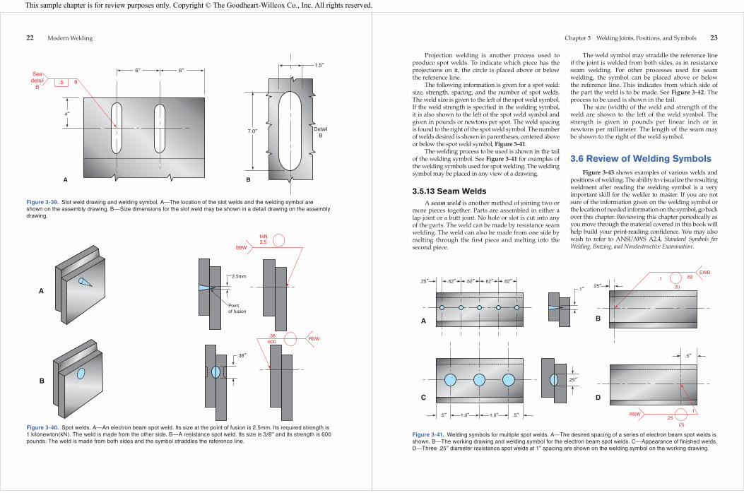
Figure 3-39. Slot weld drawing and welding symbol. A—The location of the slot welds and the welding symbol are shown on the assembly drawing. B—Size dimensions for the slot weld may be shown in a detail drawing on the assembly drawing.
A
Seedetail
B.5 6
4″
6″ 6″ 1.5″
7.0″ DetailB
B
Figure 3-40. Spot welds. A—An electron beam spot weld. Its size at the point of fusion is 2.5mm. Its required strength is 1 kilonewton(kN). The weld is made from the other side. B—A resistance spot weld. Its size is 3/8″ and its strength is 600 pounds. The weld is made from both sides and the symbol straddles the reference line.
2.5mm
Pointof fusion
EBW
1kN2.5
.38″
.38600
RSW
A
B
Chapter 3 Welding Joints, Positions, and Symbols 23
Projection welding is another process used to produce spot welds. To indicate which piece has the projections on it, the circle is placed above or below the reference line.
The following information is given for a spot weld: size, strength, spacing, and the number of spot welds. The weld size is given to the left of the spot weld symbol. If the weld strength is specifi ed in the welding symbol, it is also shown to the left of the spot weld symbol and given in pounds or newtons per spot. The weld spacing is found to the right of the spot weld symbol. The number of welds desired is shown in parentheses, centered above or below the spot weld symbol, Figure 3-41.
The welding process to be used is shown in the tail of the welding symbol. See Figure 3-41 for examples of the welding symbols used for spot welding. The welding symbol may be placed in any view of a drawing.
3.5.13 Seam WeldsA seam weld is another method of joining two or
more pieces together. Parts are assembled in either a lap joint or a butt joint. No hole or slot is cut into any of the parts. The weld can be made by resistance seam welding. The weld can also be made from one side by melting through the fi rst piece and melting into the second piece.
The weld symbol may straddle the reference line if the joint is welded from both sides, as in resistance seam welding. For other processes used for seam welding, the symbol can be placed above or below the reference line. This indicates from which side of the part the weld is to be made. See Figure 3-42. The process to be used is shown in the tail.
The size (width) of the weld and strength of the weld are shown to the left of the weld symbol. The strength is given in pounds per linear inch or in newtons per millimeter. The length of the seam may be shown to the right of the weld symbol.
3.6 Review of Welding SymbolsFigure 3-43 shows examples of various welds and
positions of welding. The ability to visualize the resulting weldment after reading the welding symbol is a very important skill for the welder to master. If you are not sure of the information given on the welding symbol or the location of needed information on the symbol, go back over this chapter. Reviewing this chapter periodically as you move through the material covered in this book will help build your print-reading confi dence. You may also wish to refer to ANSI/AWS A2.4, Standard Symbols for Welding, Brazing, and Nondestructive Examination.
Figure 3-41. Welding symbols for multiple spot welds. A—The desired spacing of a series of electron beam spot welds is shown. B—The working drawing and welding symbol for the electron beam spot welds. C—Appearance of fi nished welds. D—Three .25″ diameter resistance spot welds at 1″ spacing are shown on the welding symbol on the working drawing.
.25″ .62″ .62″ .62″ .62″.1″ .25″
EWB.62
(5)
.1
.5″
RSW.25
(3)
1
A
C
B
D
.5″ .5″1.0″ 1.0″
.25″
This sample chapter is for review purposes only. Copyright © The Goodheart-Willcox Co., Inc. All rights reserved.

24 Modern Welding
3.7 Electrode AnglesThe American Welding Society uses two terms
to describe the position of the electrode, gun or torch. These terms are used throughout this book and in industry to describe the position of the electrode in relation to the material being welded. The two terms used to describe the electrode angle, or position, are the travel angle and the work angle.
3.7.1 Travel AngleThe travel angle is the angle measured from
a line perpendicular to the weld axis in the plane defi ned by the weld axis and the electrode axis. Figure 3-44 shows a groove weld in the fl at position. The weld axis and a line perpendicular to the weld axis are shown in Figure 3-44A. Figure 3-44B adds a plane and an electrode. The plane goes through the weld axis and the electrode axis. Figure 3-44C shows how the travel angle is measured. The travel angle is the angle between a line perpendicular to the weld axis and the electrode. The angle is measured in the plane containing the weld axis and the electrode axis. The travel angle shown is about 20°.
Figure 3-45 shows a fi llet weld in the horizontal position. The weld axis and a line perpendicular to the weld axis are shown in Figure 3-45A. Figure 3-45B adds a plane and an electrode. The plane goes through the weld axis and the electrode axis. Figure 3-45C shows how the travel angle is measured. The travel angle is the angle between a line perpendicular to the weld axis and the electrode. The angle is measured in the plane containing the weld axis and the electrode axis. The travel angle shown is about 20°.
When the top of the electrode leads the welding end of the electrode, and the welding arc is pointing back toward the weld bead, the travel angle is called a drag angle or a drag travel angle. This is also known as backhand welding. If the welding end of the elec-trode points forward in the direction of travel, the angle is called a push angle or a push travel angle. This is also known as forehand welding.
Figure 3-42. Seam welds. A—An illustration of a seam weld made with the electron beam. Its size at the fusion point is .1″. B—The welding symbol and weld symbol for the electron beam seam weld shown in A. C—A fi nished seam weld made using the resistance welding process. D—This welding drawing and weld symbol will produce the weld shown in C.
.1″
.38″
.38.1
EBWA
C
B
D
RSEW
Flat edgeweld
VerticalT-weld
Horizontalbutt weld
Flat buttweld
Flat doublebutt weld
Overheaddouble buttweld
Flat lap weldPlug weld
HorizontalT-weld
Overheadlap weld
Figure 3-43. Examples of various types of welds in various positions.
Chapter 3 Welding Joints, Positions, and Symbols 25
Figure 3-44. Travel angle in a groove weld. The travel angle is measured from the electrode axis to a line perpendicular to the weld axis in the plane defi ned by the weld axis and the electrode axis. A—The weld axis and a line perpendicular to the weld axis are shown. B—The plane determined by the weld axis and the electrode axis is shown. C—The travel angle is shown.
A
Weldaxis
Perpendicularto weld axis
B
Perpendicularto weld axis
Plane defined by weldaxis and electrode axis
Weldaxis
Electrodeaxis
C
Perpendicularto weld axis
Plane defined by weldaxis and electrode axis
Weldaxis
Electrodeaxis
Travel angle
Figure 3-45. Travel angle in a fi llet weld. The travel angle is measured from the electrode axis to a line perpendicular to the weld axis in the plane defi ned by the weld axis and the electrode axis. A—The weld axis and a line perpendicular to the weld axis are shown. B—The plane determined by the weld axis and the electrode axis is shown. C—The travel angle is shown.
A
Perpendicularto weld axis
Weld axis
B
Perpendicularto weld axis
Electrodeaxis
Weld axis
Planedefinedby weldaxis andelectrode
axis
C
Perpendicularto weld axis
Travelangle
Weld axis
Planedefinedby weldaxis andelectrode
axis
Electrodeaxis
This sample chapter is for review purposes only. Copyright © The Goodheart-Willcox Co., Inc. All rights reserved.

26 Modern Welding
3.7.2 Work AngleThe work angle is the angle measured from a line
perpendicular to the major or nonbutting surface to the plane containing the weld axis and the centerline of the electrode.
Figure 3-46 shows a fi llet weld in the horizontal position. The weld axis and a line perpendicular to the major or nonbutting surface are shown in Figure 3-46A. Figure 3-46B adds a plane and an elec-trode. The plane goes through the weld axis and the electrode axis. Figure 3-46C shows how the work angle is measured. The work angle is the angle between a line perpendicular to the nonbutting surface and the plane containing the weld axis and the electrode axis. The work angle shown is about 45°.
3.7.3 Commonly Used AnglesThe work angle drawn in Figure 3-44C is zero.
Usually when welding a butt weld the work angle is zero. The electrode is in line with the weld bead. Often when welding a fi llet weld the work angle is 45°. Angles do not change when describing horizontal, vertical or overhead weld angles. The angles are measured as described. The weld axis is in a different orientation, but the measured angles remain the same.
Drag or push travel angles usually range from zero to 40°. Some welding applications use a greater travel angle. Figures 3-47 and 3-48 show the range of drag angle, push angle, and work angle for butt and fi llet welds. A large push angle, up to 85° is used for gouging.
A
Perpendicularto nonbutting
surface
Weldaxis
Nonbuttingsurface
Perpendicularto nonbutting
surface
Plane definedby weld axis
and electrode axis
Nonbuttingsurface
Weldaxis
B
Electrodeaxis
C
Perpendicularto nonbutting
surface
Plane definedby weld axis
and electrode axis
Workangle
Nonbuttingsurface
Weldaxis
Electrodeaxis
Figure 3-46. Work angle for an inside corner joint. The work angle is measured from a line perpendicular to the major or nonbutting surface to the plane containing the weld axis and the centerline of the electrode. A—The weld axis and a line perpendicular to the nonbutting surface are shown. B—The plane defi ned by the weld axis and the electrode axis are shown. C—The work angle is shown.
Chapter 3 Welding Joints, Positions, and Symbols 27
Figure 3-47. Travel angles on a groove weld. Push travel angles, or forehand welding, has the fl ame, gun, or electrode pointing in the direction of travel. Drag travel angles, or backhand welding, has the fl ame, gun, or electrode pointing opposite the direction of travel.
Perpendicularto weld axis
Push travel angle
Plane defined by weldaxis and electrode axis
Weldaxis
Electrodeaxis
Drag travelangle
Figure 3-48. Travel and work angles on a fi llet weld. Work angles can range from to 0° to 90°. Typical work angles for fi llet welds are 30° to 60° and would be measured from the vertical piece in this illustration.
Perpendicularto weld axis
Drag travelangle
Weldaxis
Planedefinedby weldaxis andelectrode
axis
Push travelangle
This sample chapter is for review purposes only. Copyright © The Goodheart-Willcox Co., Inc. All rights reserved.

28 Modern Welding
Test Your KnowledgeWrite your answers on a separate sheet of paper. Do not write in this book.
1. List the fi ve basic welding joints. 2. List fi ve things the welding symbol will tell the
welder about the weld that is to be made. 3. Why is the tail used on the welding symbol? 4. When used on the welding symbol, what does
the weld symbol tell the welder? 5. The information below the reference line refers
to the _____ side of the weld. 6. Where does the root opening appear on a groove
weld symbol? 7. What information is shown in parentheses in “E”
position in Figure 3-21? 8. On a chain intermittent welding symbol, are the
fi llet weld symbols aligned or offset? 9. An intermittent fi llet weld with the length and
pitch dimensions of 4-10 has how much space between the weld segments?
10. On a separate sheet of paper, sketch the complete welding symbol for the weld sketched in the space above. The metal part shown is not to be ground or cut prior to welding, and the weld is to be continuous rather than intermittent.
1/4
1/4
Refer to the welding symbol above when answering Questions 11 through 16:
11. Which piece of metal is to be ground, machined, or cut prior to welding?
12. What does the small, half-round symbol mean? 13. What shape is the weld face to be and what
method will be used to fi nish it? 14. Is the weld made in the shop or on site (in the
fi eld)? 15. At what angle is the one piece ground, and how
far apart are the pieces at the root of the weld? 16. Is the weld made continuously, or is it intermit-
tent? If intermittent, how long is each weld? How far apart are the welds, center-to-center?
Refer to the welding symbol above when answering Questions 17 through 19.
17. What type of weld is to be made? 18. How many welds will be made? 19. What size are the welds? 20. What kind of weld symbol(s) may straddle the
reference line?
2-6
1/1645G
A
RSW0.25
(4)
This sample chapter is for review purposes only. Copyright © The Goodheart-Willcox Co., Inc. All rights reserved.