Leak Testing Instruments - Intrade · vacuum Leak Testing Instruments Helium Leak Detectors C17...
28
vacuum Leak Testing Instruments Helium Leak Detectors C17 180.01.02 Excerpt from the Leybold Vacuum Full Line Catalog 2005 Product Section C17 Edition May 2005
Transcript of Leak Testing Instruments - Intrade · vacuum Leak Testing Instruments Helium Leak Detectors C17...
vacuum
Leak Testing InstrumentsHelium Leak Detectors
C17
180.01.02Excerpt from theLeybold Vacuum Full Line Catalog 2005Product Section C17Edition May 2005
C17
Contents
GeneralApplications and Accessories . . . . . . . . . . . . . . . . . . . . . . . . . . . . . C17.03
Leak Detection - Leak Testing . . . . . . . . . . . . . . . . . . . . . . . . . . . . . C17.04
Leak Detection Methods . . . . . . . . . . . . . . . . . . . . . . . . . . . . . . . . . C17.05
Operating Principles of the Helium Leak Detectors . . . . . . . . . . . . . . C17.07
ProductsHelium Leak Detectors
PhoeniXL 300 . . . . . . . . . . . . . . . . . . . . . . . . . . . . . . . . . . . . . . . C17.10
PhoeniXL 300 Dry . . . . . . . . . . . . . . . . . . . . . . . . . . . . . . . . . . . . C17.12
PhoeniXL 300 Modul . . . . . . . . . . . . . . . . . . . . . . . . . . . . . . . . . . C17.14
Product-Related AccessoriesCalibrated Leaks for Vacuum and Sniffer Aplications . . . . . . . . . . . . C17.18
Screw-in Calibrated Leaks . . . . . . . . . . . . . . . . . . . . . . . . . . . . . . . . C17.20
Accessories for the PhoeniXL 300, PhoeniXL 300 Dry and PhoeniXL 300 Modul . . . . . . . C17.22
Helium Sample Probes (Sniffers) . . . . . . . . . . . . . . . . . . . . . . . . . . . C17.24
Other AccessoriesConnection Flanges . . . . . . . . . . . . . . . . . . . . . . . . . . . . . . . . . . . . . C17.26
Connection Components . . . . . . . . . . . . . . . . . . . . . . . . . . . . . . . . . C17.26
Leybold Vacuum Full Line Catalog 20052
Leak Testing Instruments
Leybold Vacuum Full Line Catalog 2005 C17
General Leak Testing Instruments
3
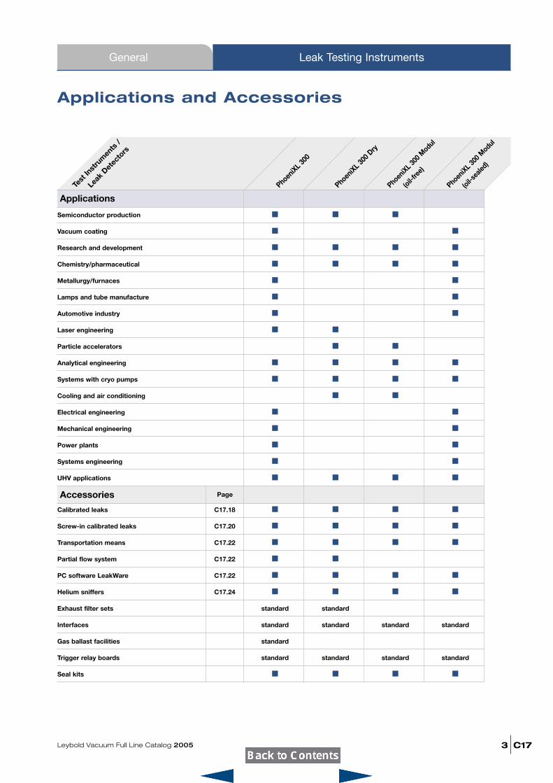
Semiconductor production � � �
Vacuum coating � �
Research and development � � � �
Chemistry/pharmaceutical � � � �
Metallurgy/furnaces � �
Lamps and tube manufacture � �
Automotive industry � �
Laser engineering � �
Particle accelerators � �
Analytical engineering � � � �
Systems with cryo pumps � � � �
Cooling and air conditioning � �
Electrical engineering � �
Mechanical engineering � �
Power plants � �
Systems engineering � �
UHV applications � � � �
Calibrated leaks C17.18 � � � �
Screw-in calibrated leaks C17.20 � � � �
Transportation means C17.22 � � � �
Partial flow system C17.22 � �
PC software LeakWare C17.22 � � � �
Helium sniffers C17.24 � � � �
Exhaust filter sets standard standard
Interfaces standard standard standard standard
Gas ballast facilities standard
Trigger relay boards standard standard standard standard
Seal kits � � � �
Accessories
Test
Inst
rum
ents
/
Leak
Detec
tors
PhoeniXL 30
0
PhoeniXL 30
0 Dry
PhoeniXL 30
0 Modul
(oil-fre
e)
Page
Applications and Accessories
ApplicationsPhoen
iXL 300 M
odul
(oil-sea
led)
C17
General
Leybold Vacuum Full Line Catalog 20054
Leak Testing Instruments
Leak Detection – Leak Testing
Vac
uum
met
hod
Ove
rpre
ssur
e m
etho
d
Helium leak detector PhoeniXL 300 with helium sniffer
103................100 10-1 10-2 10-3 10-4 10-5 10-6 10-7 10-8 10-9 10-10 10-11 10-12 mbar · l · s-1
Pressure rise
Helium leak detector PhoeniXL 300 with partial flow pump set
Helium leak detector PhoeniXL 300 Modul
Helium leak detector PhoeniXL Dry
Bubble test
Pressure drop test
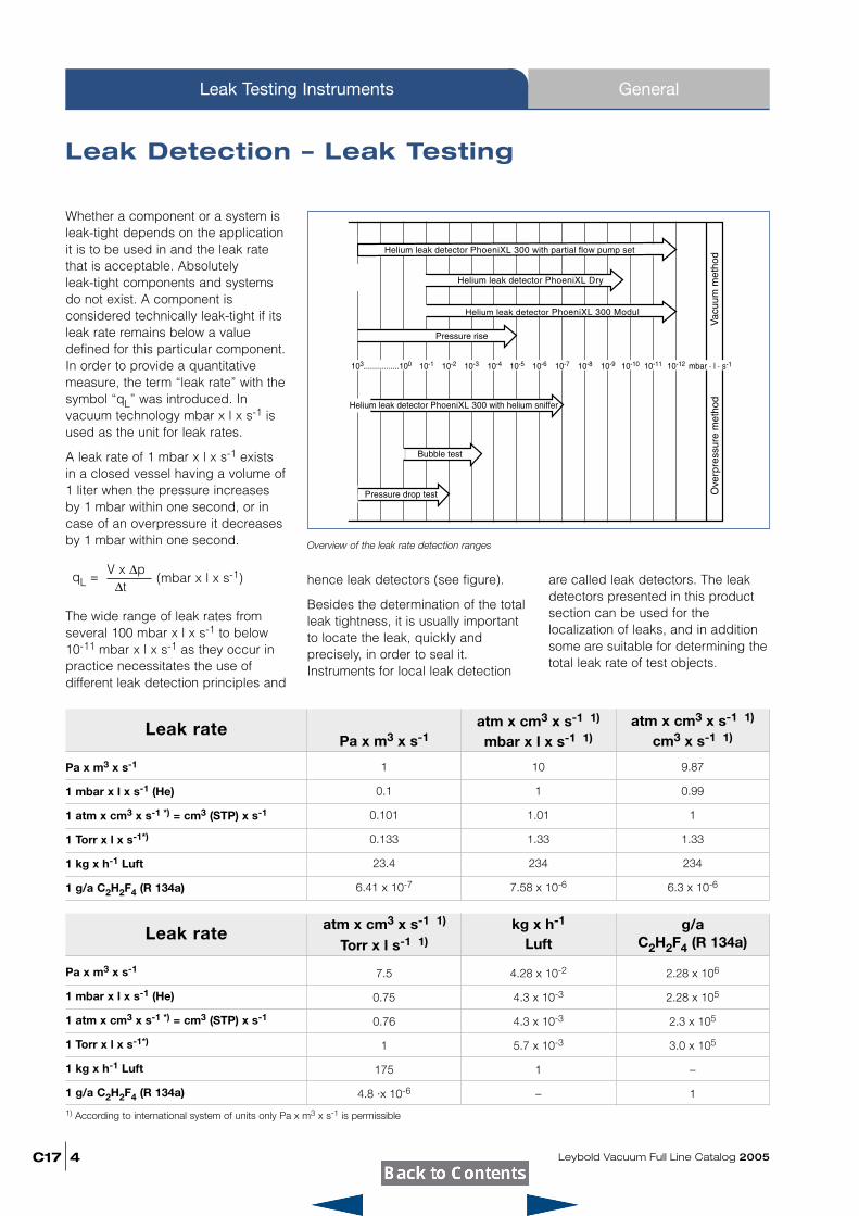
Whether a component or a system isleak-tight depends on the applicationit is to be used in and the leak ratethat is acceptable. Absolutely leak-tight components and systemsdo not exist. A component is considered technically leak-tight if itsleak rate remains below a value defined for this particular component.In order to provide a quantitative measure, the term “leak rate” with thesymbol “qL” was introduced. In vacuum technology mbar x l x s-1 isused as the unit for leak rates.
A leak rate of 1 mbar x l x s-1 existsin a closed vessel having a volume of1 liter when the pressure increasesby 1 mbar within one second, or incase of an overpressure it decreasesby 1 mbar within one second.
The wide range of leak rates fromseveral 100 mbar x l x s-1 to below10-11 mbar x l x s-1 as they occur inpractice necessitates the use of different leak detection principles and
hence leak detectors (see figure).
Besides the determination of the totalleak tightness, it is usually importantto locate the leak, quickly and precisely, in order to seal it.Instruments for local leak detection
are called leak detectors. The leakdetectors presented in this productsection can be used for the localization of leaks, and in additionsome are suitable for determining thetotal leak rate of test objects.
Leak rate
Pa x m3 x s-1
1 mbar x l x s-1 (He)
1 atm x cm3 x s-1 *) = cm3 (STP) x s-1
1 Torr x l x s-1*)
1 kg x h-1 Luft
1 g/a C2H2F4 (R 134a)
1 10 9.87
0.1 1 0.99
0.101 1.01 1
0.133 1.33 1.33
23.4 234 234
6.41 x 10⁻⁷ 7.58 x 10⁻⁶ 6.3 x 10⁻⁶
Pa x m3 x s-1atm x cm3 x s-1 1)
mbar x l x s-1 1)atm x cm3 x s-1 1)
cm3 x s-1 1)
Overview of the leak rate detection ranges
Leak rate
Pa x m3 x s-1
1 mbar x l x s-1 (He)
1 atm x cm3 x s-1 *) = cm3 (STP) x s-1
1 Torr x l x s-1*)
1 kg x h-1 Luft
1 g/a C2H2F4 (R 134a)
1) According to international system of units only Pa x m3 x s-1 is permissible
7.5 4.28 x 10⁻² 2.28 x 10⁶
0.75 4.3 x 10⁻³ 2.28 x 10⁵
0.76 4.3 x 10⁻³ 2.3 x 10⁵
1 5.7 x 10⁻³ 3.0 x 10⁵
175 1 –
4.8 ·x 10-6 – 1
Torr x l s-1 1) Luft C2H2F4 (R 134a)atm x cm3 x s-1 1) kg x h-1 g/a
V x ∆p∆t
qL = (mbar x l x s-1)
Leybold Vacuum Full Line Catalog 2005 C17
General Leak Testing Instruments
5
There are two main groups of leakdetection methods; for both there arespecial instruments available:
Vacuum Methods
The equipment to be tested isevacuated. The pressure ratiobetween inside and outside is 0:1.
Overpressure Methods
The equipment to be tested ispressurized with a search gas or asearch gas mixture.
The pressure ratio between insideand outside is over 1:1.
Between the two methods there existmany variations depending on theparticular application.
General Notes
1. The lowest leak rates can only bemeasured by employing the vacuummethod, whereby the followingapplies: The lower the leak rate, thehigher the requirements areconcerning cleanness and ultimatevacuum.
2. If possible the test objects shouldbe tested under the same conditionsthat will be used in their finalapplication, i.e. parts for vacuumoperation should be tested accordingto the vacuum method and parts for
overpressure operation should betested using the overpressuremethod.
Leak Testing Based onVacuum Methods(Vacuum inside the test object)
Pressure Rise Method
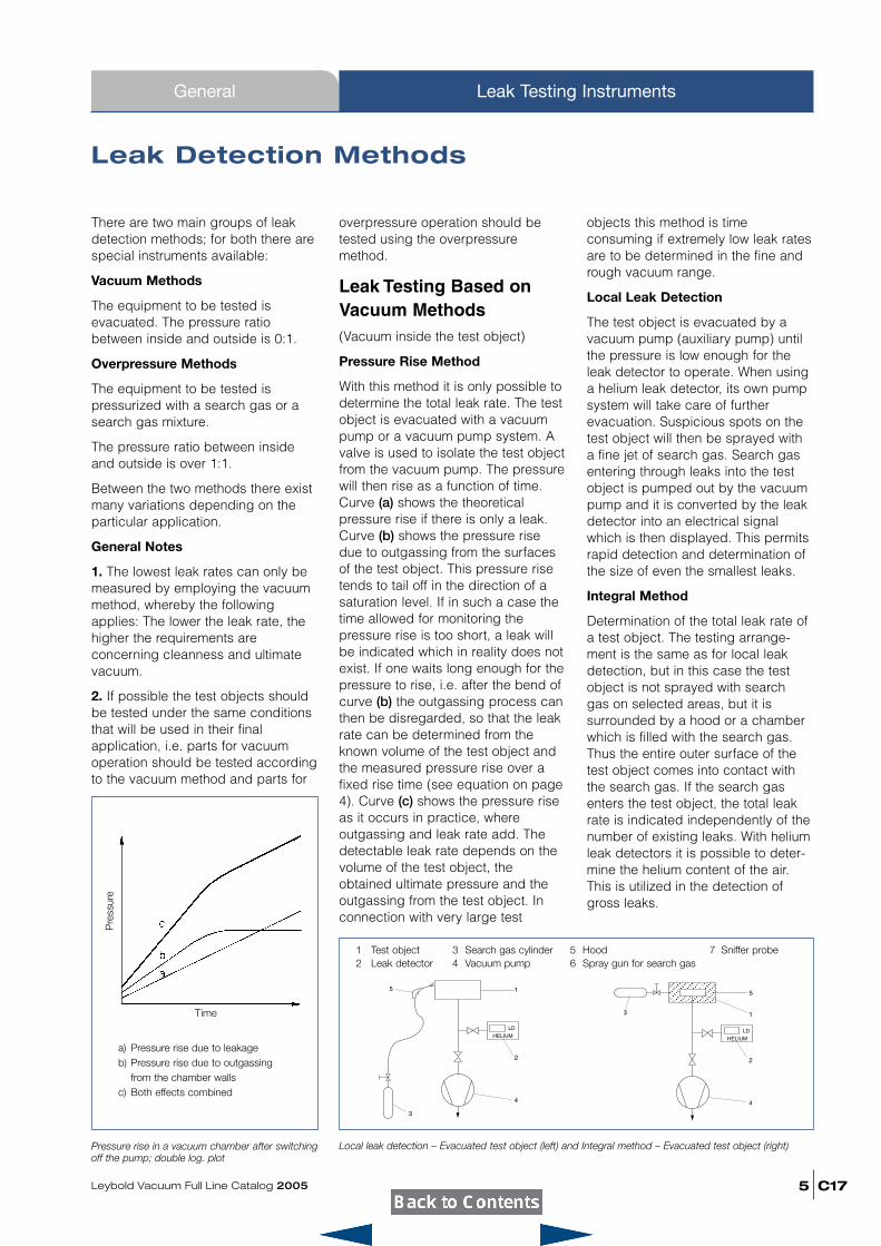
With this method it is only possible todetermine the total leak rate. The testobject is evacuated with a vacuumpump or a vacuum pump system. Avalve is used to isolate the test objectfrom the vacuum pump. The pressurewill then rise as a function of time.Curve (a) shows the theoreticalpressure rise if there is only a leak.Curve (b) shows the pressure risedue to outgassing from the surfacesof the test object. This pressure risetends to tail off in the direction of asaturation level. If in such a case thetime allowed for monitoring thepressure rise is too short, a leak willbe indicated which in reality does notexist. If one waits long enough for thepressure to rise, i.e. after the bend ofcurve (b) the outgassing process canthen be disregarded, so that the leakrate can be determined from theknown volume of the test object andthe measured pressure rise over afixed rise time (see equation on page4). Curve (c) shows the pressure riseas it occurs in practice, whereoutgassing and leak rate add. Thedetectable leak rate depends on thevolume of the test object, theobtained ultimate pressure and theoutgassing from the test object. Inconnection with very large test
objects this method is timeconsuming if extremely low leak ratesare to be determined in the fine andrough vacuum range.
Local Leak Detection
The test object is evacuated by avacuum pump (auxiliary pump) untilthe pressure is low enough for theleak detector to operate. When usinga helium leak detector, its own pumpsystem will take care of furtherevacuation. Suspicious spots on thetest object will then be sprayed witha fine jet of search gas. Search gasentering through leaks into the testobject is pumped out by the vacuumpump and it is converted by the leakdetector into an electrical signalwhich is then displayed. This permitsrapid detection and determination ofthe size of even the smallest leaks.
Integral Method
Determination of the total leak rate ofa test object. The testing arrange-ment is the same as for local leakdetection, but in this case the testobject is not sprayed with search gas on selected areas, but it issurrounded by a hood or a chamberwhich is filled with the search gas.Thus the entire outer surface of thetest object comes into contact withthe search gas. If the search gasenters the test object, the total leakrate is indicated independently of thenumber of existing leaks. With heliumleak detectors it is possible to deter-mine the helium content of the air.This is utilized in the detection ofgross leaks.
Leak Detection Methods
Local leak detection – Evacuated test object (left) and Integral method – Evacuated test object (right)Pressure rise in a vacuum chamber after switchingoff the pump; double log. plot
1
2
3
4
5
LD
HELIUM
2
3
4
LD
HELIUM
1
5
a) Pressure rise due to leakageb) Pressure rise due to outgassing
from the chamber wallsc) Both effects combined
1 Test object 3 Search gas cylinder 5 Hood 7 Sniffer probe2 Leak detector 4 Vacuum pump 6 Spray gun for search gas
Pre
ssur
e
Time
C17
General
Leybold Vacuum Full Line Catalog 20056
Leak Testing Instruments
Leak Testing Based on
Overpressure Methods(Overpressure within the test object)
Pressure Drop Method
The test object is filled with a gas (forexample air or nitrogen) until thetesting pressure is reached. Precisionvacuum gauges are used to detect apossible pressure drop during thetesting period. This method is simpleto implement, it is suitable for thedetermination of gross leaks and canbe improved upon by usingdifferential pressure gauges. Byapplying soap solutions or similar,leaks can be located.
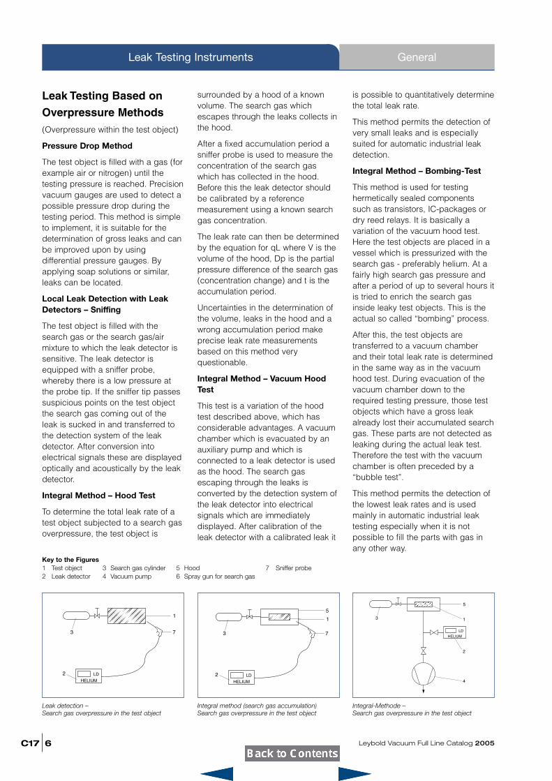
Local Leak Detection with LeakDetectors – Sniffing
The test object is filled with thesearch gas or the search gas/airmixture to which the leak detector issensitive. The leak detector isequipped with a sniffer probe,whereby there is a low pressure atthe probe tip. If the sniffer tip passessuspicious points on the test objectthe search gas coming out of theleak is sucked in and transferred tothe detection system of the leakdetector. After conversion intoelectrical signals these are displayedoptically and acoustically by the leakdetector.
Integral Method – Hood Test
To determine the total leak rate of atest object subjected to a search gasoverpressure, the test object is
surrounded by a hood of a knownvolume. The search gas whichescapes through the leaks collects inthe hood.
After a fixed accumulation period asniffer probe is used to measure theconcentration of the search gaswhich has collected in the hood.Before this the leak detector shouldbe calibrated by a referencemeasurement using a known searchgas concentration.
The leak rate can then be determinedby the equation for qL where V is thevolume of the hood, Dp is the partialpressure difference of the search gas(concentration change) and t is theaccumulation period.
Uncertainties in the determination ofthe volume, leaks in the hood and awrong accumulation period makeprecise leak rate measurementsbased on this method veryquestionable.
Integral Method – Vacuum HoodTest
This test is a variation of the hoodtest described above, which hasconsiderable advantages. A vacuumchamber which is evacuated by anauxiliary pump and which isconnected to a leak detector is usedas the hood. The search gasescaping through the leaks isconverted by the detection system ofthe leak detector into electricalsignals which are immediatelydisplayed. After calibration of theleak detector with a calibrated leak it
is possible to quantitatively determinethe total leak rate.
This method permits the detection ofvery small leaks and is especiallysuited for automatic industrial leakdetection.
Integral Method – Bombing-Test
This method is used for testinghermetically sealed componentssuch as transistors, IC-packages ordry reed relays. It is basically avariation of the vacuum hood test.Here the test objects are placed in avessel which is pressurized with thesearch gas - preferably helium. At afairly high search gas pressure andafter a period of up to several hours itis tried to enrich the search gasinside leaky test objects. This is theactual so called “bombing” process.
After this, the test objects aretransferred to a vacuum chamberand their total leak rate is determinedin the same way as in the vacuumhood test. During evacuation of thevacuum chamber down to therequired testing pressure, those testobjects which have a gross leakalready lost their accumulated searchgas. These parts are not detected asleaking during the actual leak test.Therefore the test with the vacuumchamber is often preceded by a“bubble test”.
This method permits the detection ofthe lowest leak rates and is usedmainly in automatic industrial leaktesting especially when it is notpossible to fill the parts with gas inany other way.
Leak detection – Search gas overpressure in the test object
2
3
LD
HELIUM
1
7
Integral method (search gas accumulation)Search gas overpressure in the test object
2
3
LD
HELIUM
1
7
5
Integral-Methode – Search gas overpressure in the test object
2
3
4
LD
HELIUM
1
5
Key to the Figures1 Test object 3 Search gas cylinder 5 Hood 7 Sniffer probe2 Leak detector 4 Vacuum pump 6 Spray gun for search gas
Leybold Vacuum Full Line Catalog 2005 C17
general Leak Testing Instruments
7
Operating Principles of the Helium LeakDetectors
Operating PrincipleA helium leak detector permits thelocalization of leaks and thequantitative determination of the leakrate, i.e. the gas flow through theleak. Such a leak detector istherefore a helium flow meter.
In practice the leak detectorperforms this task by firstlyevacuating the part which is to betested, so that gas from the outsidemay enter through an existing leakdue to the pressure differencepresent. If only helium is brought infront of the leak (for example byusing a spray gun) this helium flowsthrough the leak and is pumped outby the leak detector. The heliumpartial pressure present in the leakdetector is measured by a sectormass spectrometer and is displayedas a leak rate. This is usually given interms of volume flow of the helium(pV-flow).
Important SpecificationsThe two most important features of aleak detector are its measurementrange (detection limits) and itsresponse time.
The measurement range is limited bythe lowest and the highest detectableleak rate. The lowest detectable leakrate is defined by the sum of drift andnoise in the most sensitive measure-ment range. Usually the sum of noiseamplitude and zero drift per minute ismade to be equivalent to the lowestdetectable leak rate. With leakdetectors the amount of drift is solow, that the noise amplitude alonedetermines the detection limit.
The highest detectable leak ratedepends strongly on the methodemployed. Especially the counterflowmethod and partial flow operation(see description below) permit themeasurement of very high leak rateseven with a sensitive helium leakdetector. In addition the multistageswitchable high impedance inputamplifiers of the leak detectors alsopermit the measurement of high leakrates.
In practical applications, especially inthe localization of leaks the responsetime is of great significance. This is thetime it takes from spraying the test
object with helium until a measuredvalue is displayed by the leak detector.The response time of the electronicsignal conditioning circuitry is animportant factor in the overall responsetime. In the case of leak detectors theresponse time of the electronic circuitryis well below 1 s.
The volume flow rate for helium at thepoint of the test object is of decisivesignificance to leak detection oncomponents which are pumpeddown solely by the leak detector. Thisvolume flow rate provided by the leakdetector takes care of the heliumentering through a leak and itensures quick detection by the leakdetector. On the other hand thevolume of the test object delays thearrival of the helium signal. Theresponse time can be calculated onthe basis of the following simpleequation:
Response time for helium tA = 3
(for 95% of the final value)
with V = Volume of the test objectSHe = Volume flow rate for
helium at the point of the test object (or at the inlet of the leakdetector, if it alone pumps down the testobject).
V
SHe
C17
General
Leybold Vacuum Full Line Catalog 20058
Leak Testing Instruments
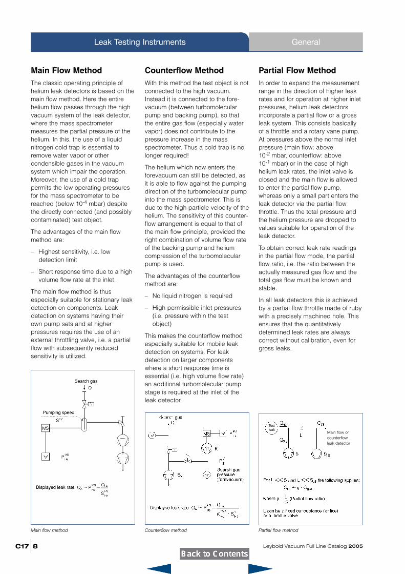
Main Flow MethodThe classic operating principle ofhelium leak detectors is based on themain flow method. Here the entirehelium flow passes through the highvacuum system of the leak detector,where the mass spectrometer measures the partial pressure of thehelium. In this, the use of a liquidnitrogen cold trap is essential toremove water vapor or other condensible gases in the vacuumsystem which impair the operation.Moreover, the use of a cold trap permits the low operating pressuresfor the mass spectrometer to be reached (below 10-4 mbar) despitethe directly connected (and possiblycontaminated) test object.
The advantages of the main flowmethod are:
– Highest sensitivity, i.e. low detection limit
– Short response time due to a highvolume flow rate at the inlet.
The main flow method is thus especially suitable for stationary leakdetection on components. Leakdetection on systems having theirown pump sets and at higher pressures requires the use of anexternal throttling valve, i.e. a partialflow with subsequently reduced sensitivity is utilized.
Counterflow MethodWith this method the test object is notconnected to the high vacuum.Instead it is connected to the fore-vacuum (between turbomolecularpump and backing pump), so thatthe entire gas flow (especially watervapor) does not contribute to thepressure increase in the massspectrometer. Thus a cold trap is nolonger required!
The helium which now enters theforevacuum can still be detected, asit is able to flow against the pumpingdirection of the turbomolecular pumpinto the mass spectrometer. This isdue to the high particle velocity of thehelium. The sensitivity of this counter-flow arrangement is equal to that ofthe main flow principle, provided theright combination of volume flow rateof the backing pump and heliumcompression of the turbomolecularpump is used.
The advantages of the counterflowmethod are:
– No liquid nitrogen is required
– High permissible inlet pressures(i.e. pressure within the testobject)
This makes the counterflow methodespecially suitable for mobile leakdetection on systems. For leak detection on larger componentswhere a short response time isessential (i.e. high volume flow rate)an additional turbomolecular pumpstage is required at the inlet of theleak detector.
Main flow method Counterflow method Partial flow method
Partial Flow MethodIn order to expand the measurementrange in the direction of higher leakrates and for operation at higher inletpressures, helium leak detectorsincorporate a partial flow or a grossleak system. This consists basicallyof a throttle and a rotary vane pump.At pressures above the normal inletpressure (main flow: above 10-2 mbar, counterflow: above 10-1 mbar) or in the case of high helium leak rates, the inlet valve isclosed and the main flow is allowedto enter the partial flow pump, whereas only a small part enters theleak detector via the partial flowthrottle. Thus the total pressure andthe helium pressure are dropped tovalues suitable for operation of theleak detector.
To obtain correct leak rate readingsin the partial flow mode, the partialflow ratio, i.e. the ratio between theactually measured gas flow and thetotal gas flow must be known andstable.
In all leak detectors this is achievedby a partial flow throttle made of rubywith a precisely machined hole. Thisensures that the quantitatively determined leak rates are always correct without calibration, even forgross leaks.
Main flow orcounterflowleak detector
Testleak
Leybold Vacuum Full Line Catalog 2005 C17
General Leak Testing Instruments
9
Calibration of Helium Leak
Detectors with Calibrated
LeaksIn the process of leak detection oneexpects that a test object which doesnot have a leak produces a zero reading on the leak detector. In thisany malfunctions are excluded. Thuscalibrated leaks, i.e. artificial leakswhich produce a known helium leakrate are essential for reliable results.
To obtain a quantitatively correct leakrate reading the sensitivity of the leakdetector must also be adjusted. Thisrequires the use of a calibrated leak.
Leybold offers calibrated helium leaksof various designs covering the rangebetween 10-9 to 10-4 mbar x l x s-1
as part of the standard range of products. All leak rates are traceableto the standards of the German
Calibration Service controlled by thePTB (Federal Institution of Physicsand Technology). If requested eachhelium calibrated leak can be supplied with a calibration certificateissued by the German CalibrationService. The calibration itself is performed by the German CalibrationService for Vacuum which is run byLeybold on behalf of the PTB.
C17
Helium Leak Detectors
Leybold Vacuum Full Line Catalog 200510
Leak Testing Instruments
Advantages to the User� Lowest detectable leak rate
� Short He recovering time condition
� Quick start-up
� Extremely fast response time
� Oil-free gas admission system
� One of the smallest helium leakdetectors in the world
� High sensitivity
� Fast leak rate readout also at lowleak rates
Typical ApplicationsLeak tests in connection with
� Quality assurance
� Automotive industry
� Analytical instruments
� Systems manufacture
� Power station engineering
� Research and development
� Semiconductor industry
� High vacuum and ultra-highvacuum engineering
� Ideal tool for industrial seriesproduction testing – in the coolingand air conditioning industries, forexample
In connection with the sniffer lineswhich are available as accessoriesthe PhoeniXL 300 may also be usedas a sniffer leak detector.
In connection with a partial flowpump set the PhoeniXL 300 may alsobe used for the detection of leaks onlarge vessels.
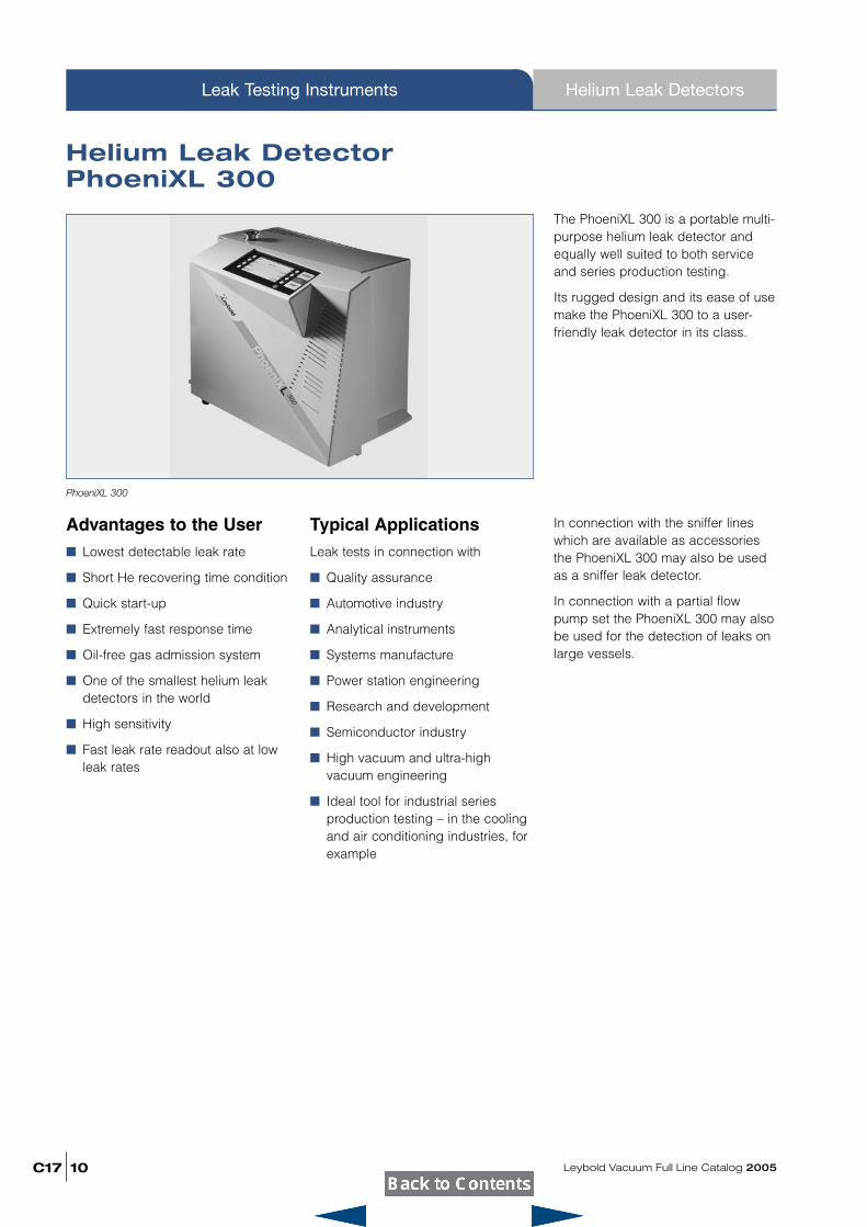
Helium Leak DetectorPhoeniXL 300
The PhoeniXL 300 is a portable multi-purpose helium leak detector andequally well suited to both serviceand series production testing.
Its rugged design and its ease of usemake the PhoeniXL 300 to a user-friendly leak detector in its class.
PhoeniXL 300
Ordering Information
Leybold Vacuum Full Line Catalog 2005 C17
Helium Leak Detectors Leak Testing Instruments
11
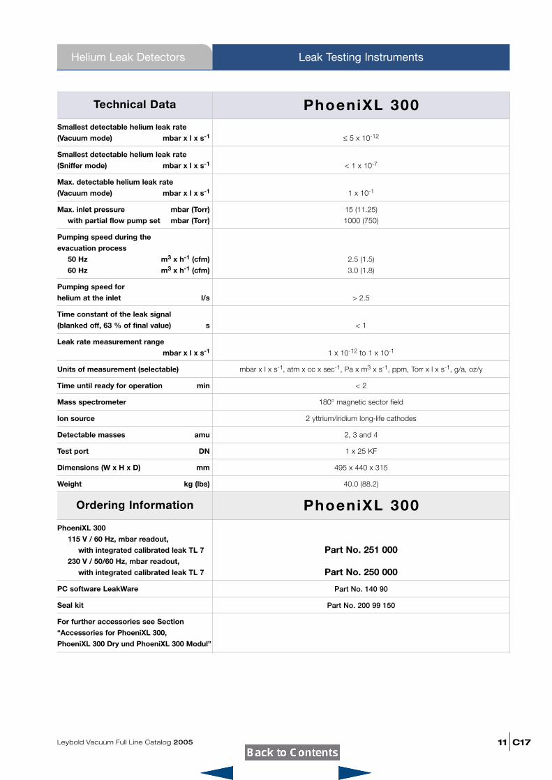
Technical Data
Smallest detectable helium leak rate
(Vacuum mode) mbar x l x s-1
Smallest detectable helium leak rate
(Sniffer mode) mbar x l x s-1
Max. detectable helium leak rate
(Vacuum mode) mbar x l x s-1
Max. inlet pressure mbar (Torr)
with partial flow pump set mbar (Torr)
Pumping speed during the
evacuation process
50 Hz m3 x h-1 (cfm)
60 Hz m3 x h-1 (cfm)
Pumping speed for
helium at the inlet l/s
Time constant of the leak signal
(blanked off, 63 % of final value) s
Leak rate measurement range
mbar x l x s-1
Units of measurement (selectable)
Time until ready for operation min
Mass spectrometer
Ion source
Detectable masses amu
Test port DN
Dimensions (W x H x D) mm
Weight kg (lbs)
≤ 5 x 10-12
< 1 x 10⁻⁷
1 x 10⁻¹
15 (11.25)
1000 (750)
2.5 (1.5)
3.0 (1.8)
> 2.5
< 1
1 x 10-12 to 1 x 10⁻¹
mbar x l x s-1, atm x cc x sec-1, Pa x m3 x s-1, ppm, Torr x l x s-1, g/a, oz/y
< 2
180° magnetic sector field
2 yttrium/iridium long-life cathodes
2, 3 and 4
1 x 25 KF
495 x 440 x 315
40.0 (88.2)
PhoeniXL 300
115 V / 60 Hz, mbar readout,
with integrated calibrated leak TL 7
230 V / 50/60 Hz, mbar readout,
with integrated calibrated leak TL 7
PC software LeakWare
Seal kit
For further accessories see Section
“Accessories for PhoeniXL 300,
PhoeniXL 300 Dry und PhoeniXL 300 Modul”
Part No. 251 000
Part No. 250 000
Part No. 140 90
Part No. 200 99 150
PhoeniXL 300
PhoeniXL 300
C17
Helium Leak Detectors
Leybold Vacuum Full Line Catalog 200512
Leak Testing Instruments
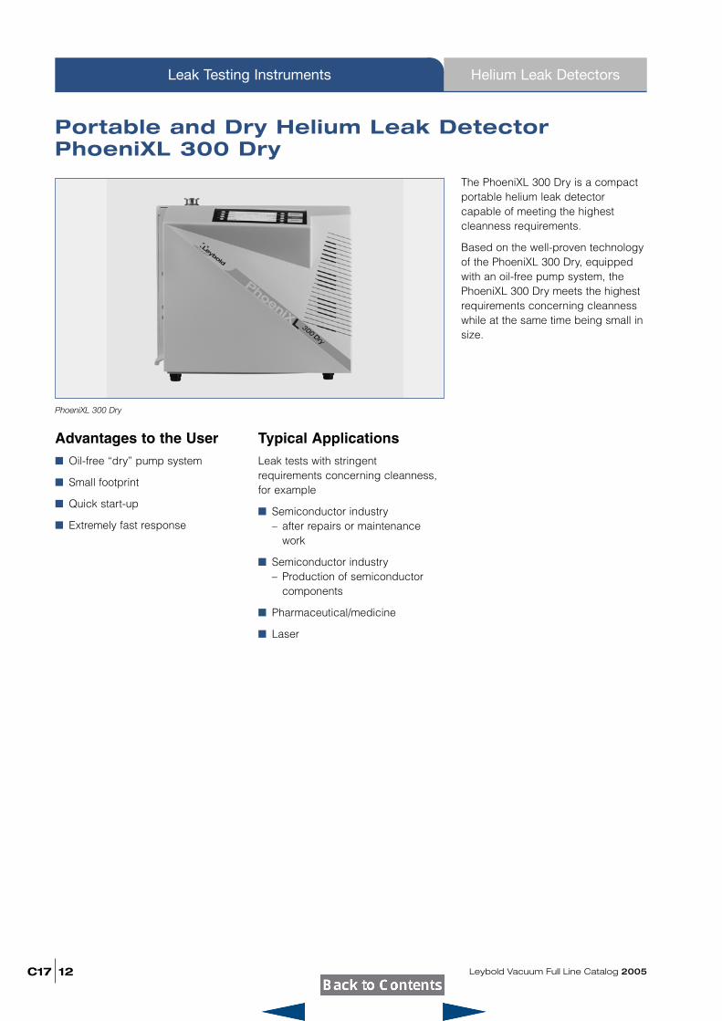
Portable and Dry Helium Leak DetectorPhoeniXL 300 Dry
Advantages to the User� Oil-free “dry” pump system
� Small footprint
� Quick start-up
� Extremely fast response
The PhoeniXL 300 Dry is a compactportable helium leak detectorcapable of meeting the highestcleanness requirements.
Based on the well-proven technologyof the PhoeniXL 300 Dry, equippedwith an oil-free pump system, thePhoeniXL 300 Dry meets the highestrequirements concerning cleannesswhile at the same time being small insize.
Typical ApplicationsLeak tests with stringentrequirements concerning cleanness,for example
� Semiconductor industry– after repairs or maintenance
work
� Semiconductor industry– Production of semiconductor
components
� Pharmaceutical/medicine
� Laser
PhoeniXL 300 Dry
Leybold Vacuum Full Line Catalog 2005 C17
Helium Leak Detectors Leak Testing Instruments
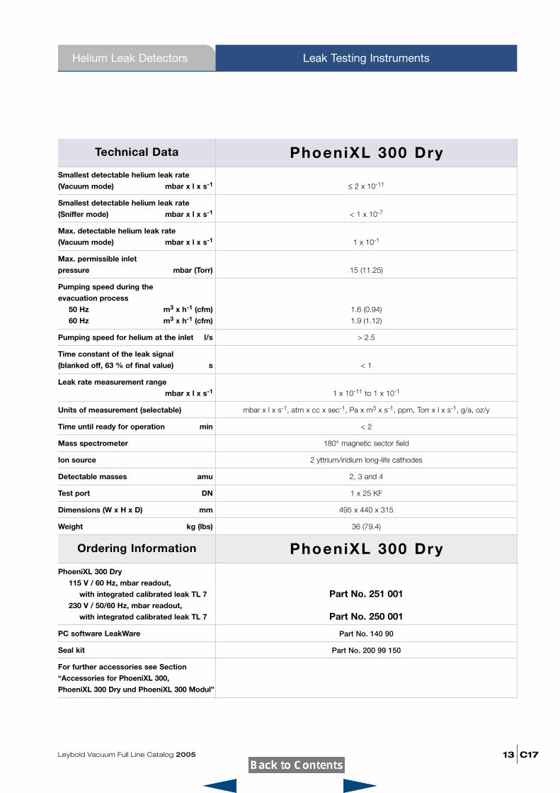
13
Technical Data
Smallest detectable helium leak rate
(Vacuum mode) mbar x l x s-1
Smallest detectable helium leak rate
(Sniffer mode) mbar x l x s-1
Max. detectable helium leak rate
(Vacuum mode) mbar x l x s-1
Max. permissible inlet
pressure mbar (Torr)
Pumping speed during the
evacuation process
50 Hz m3 x h-1 (cfm)
60 Hz m3 x h-1 (cfm)
Pumping speed for helium at the inlet l/s
Time constant of the leak signal
(blanked off, 63 % of final value) s
Leak rate measurement range
mbar x l x s-1
Units of measurement (selectable)
Time until ready for operation min
Mass spectrometer
Ion source
Detectable masses amu
Test port DN
Dimensions (W x H x D) mm
Weight kg (lbs)
≤ 2 x 10-11
< 1 x 10⁻⁷
1 x 10⁻¹
15 (11.25)
1.6 (0.94)
1.9 (1.12)
> 2.5
< 1
1 x 10-11 to 1 x 10⁻¹
mbar x l x s-1, atm x cc x sec-1, Pa x m3 x s-1, ppm, Torr x l x s-1, g/a, oz/y
< 2
180° magnetic sector field
2 yttrium/iridium long-life cathodes
2, 3 and 4
1 x 25 KF
495 x 440 x 315
36 (79.4)
Ordering Information
PhoeniXL 300 Dry
115 V / 60 Hz, mbar readout,
with integrated calibrated leak TL 7
230 V / 50/60 Hz, mbar readout,
with integrated calibrated leak TL 7
PC software LeakWare
Seal kit
For further accessories see Section
“Accessories for PhoeniXL 300,
PhoeniXL 300 Dry und PhoeniXL 300 Modul”
Part No. 251 001
Part No. 250 001
Part No. 140 90
Part No. 200 99 150
PhoeniXL 300 Dry
PhoeniXL 300 Dry
C17
Helium Leak Detectors
Leybold Vacuum Full Line Catalog 200514
Leak Testing Instruments
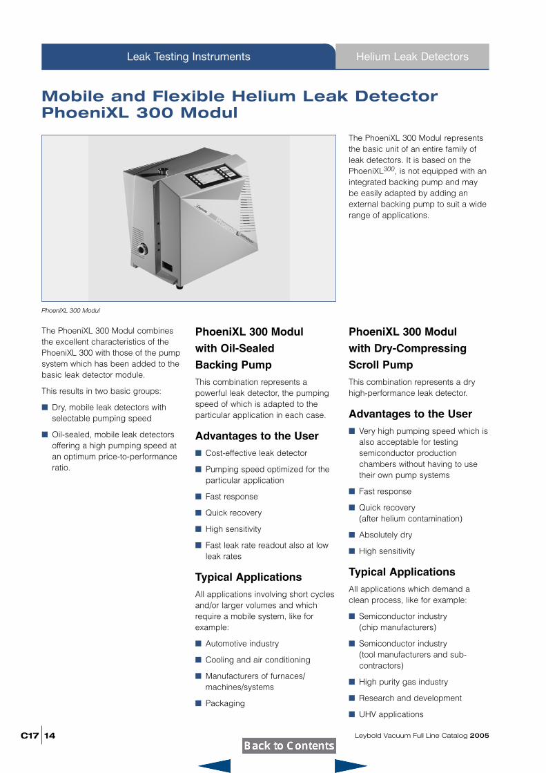
Mobile and Flexible Helium Leak DetectorPhoeniXL 300 Modul
The PhoeniXL 300 Modul combinesthe excellent characteristics of thePhoeniXL 300 with those of the pumpsystem which has been added to thebasic leak detector module.
This results in two basic groups:
� Dry, mobile leak detectors withselectable pumping speed
� Oil-sealed, mobile leak detectorsoffering a high pumping speed atan optimum price-to-performanceratio.
PhoeniXL 300 Modul
with Oil-Sealed
Backing PumpThis combination represents apowerful leak detector, the pumpingspeed of which is adapted to theparticular application in each case.
Advantages to the User� Cost-effective leak detector
� Pumping speed optimized for theparticular application
� Fast response
� Quick recovery
� High sensitivity
� Fast leak rate readout also at lowleak rates
Typical ApplicationsAll applications involving short cyclesand/or larger volumes and whichrequire a mobile system, like forexample:
� Automotive industry
� Cooling and air conditioning
� Manufacturers of furnaces/machines/systems
� Packaging
The PhoeniXL 300 Modul representsthe basic unit of an entire family ofleak detectors. It is based on thePhoeniXL300, is not equipped with anintegrated backing pump and maybe easily adapted by adding anexternal backing pump to suit a widerange of applications.
PhoeniXL 300 Modul
with Dry-Compressing
Scroll PumpThis combination represents a dryhigh-performance leak detector.
Advantages to the User� Very high pumping speed which is
also acceptable for testingsemiconductor productionchambers without having to usetheir own pump systems
� Fast response
� Quick recovery (after helium contamination)
� Absolutely dry
� High sensitivity
Typical ApplicationsAll applications which demand aclean process, like for example:
� Semiconductor industry (chip manufacturers)
� Semiconductor industry (tool manufacturers and sub-contractors)
� High purity gas industry
� Research and development
� UHV applications
PhoeniXL 300 Modul
Leybold Vacuum Full Line Catalog 2005 C17
Helium Leak Detectors Leak Testing Instruments
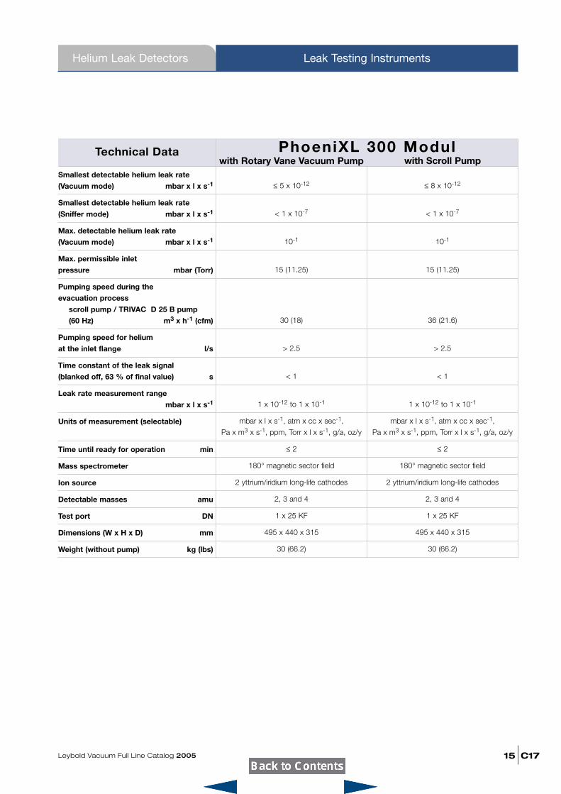
15
Technical Datawith Rotary Vane Vacuum Pump
Smallest detectable helium leak rate
(Vacuum mode) mbar x l x s-1
Smallest detectable helium leak rate
(Sniffer mode) mbar x l x s-1
Max. detectable helium leak rate
(Vacuum mode) mbar x l x s-1
Max. permissible inlet
pressure mbar (Torr)
Pumping speed during the
evacuation process
scroll pump / TRIVAC D 25 B pump
(60 Hz) m3 x h-1 (cfm)
Pumping speed for helium
at the inlet flange l/s
Time constant of the leak signal
(blanked off, 63 % of final value) s
Leak rate measurement range
mbar x l x s-1
Units of measurement (selectable)
Time until ready for operation min
Mass spectrometer
Ion source
Detectable masses amu
Test port DN
Dimensions (W x H x D) mm
Weight (without pump) kg (lbs)
≤ 5 x 10-12 ≤ 8 x 10-12
< 1 x 10⁻⁷ < 1 x 10⁻⁷
10-1 10-1
15 (11.25) 15 (11.25)
30 (18) 36 (21.6)
> 2.5 > 2.5
< 1 < 1
1 x 10-12 to 1 x 10⁻¹ 1 x 10-12 to 1 x 10⁻¹
mbar x l x s-1, atm x cc x sec-1, mbar x l x s-1, atm x cc x sec-1,
Pa x m3 x s-1, ppm, Torr x l x s-1, g/a, oz/y Pa x m3 x s-1, ppm, Torr x l x s-1, g/a, oz/y
≤ 2 ≤ 2
180° magnetic sector field 180° magnetic sector field
2 yttrium/iridium long-life cathodes 2 yttrium/iridium long-life cathodes
2, 3 and 4 2, 3 and 4
1 x 25 KF 1 x 25 KF
495 x 440 x 315 495 x 440 x 315
30 (66.2) 30 (66.2)
with Scroll PumpPhoeniXL 300 Modul
C17
Helium Leak Detectors
Leybold Vacuum Full Line Catalog 200516
Leak Testing Instruments
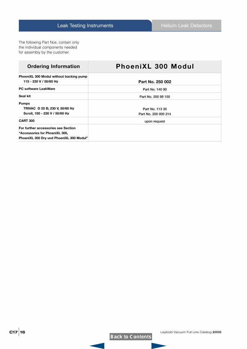
Ordering Information
PhoeniXL 300 Modul without backing pump
115 - 230 V / 50/60 Hz
PC software LeakWare
Seal kit
Pumps
TRIVAC D 25 B; 230 V, 50/60 Hz
Scroll, 100 - 230 V / 50/60 Hz
CART 300
For further accessories see Section
“Accessories for PhoeniXL 300,
PhoeniXL 300 Dry und PhoeniXL 300 Modul”
Part No. 250 002
Part No. 140 90
Part No. 200 99 150
Part No. 113 35
Part No. 200 000 214
upon request
PhoeniXL 300 Modul
The following Part Nos. contain onlythe individual components neededfor assembly by the customer.
Leybold Vacuum Full Line Catalog 2005 C17
Helium Leak Detectors Leak Testing Instruments
17
Notes
C17
Accessories
Leybold Vacuum Full Line Catalog 200518
Leak Testing Instruments
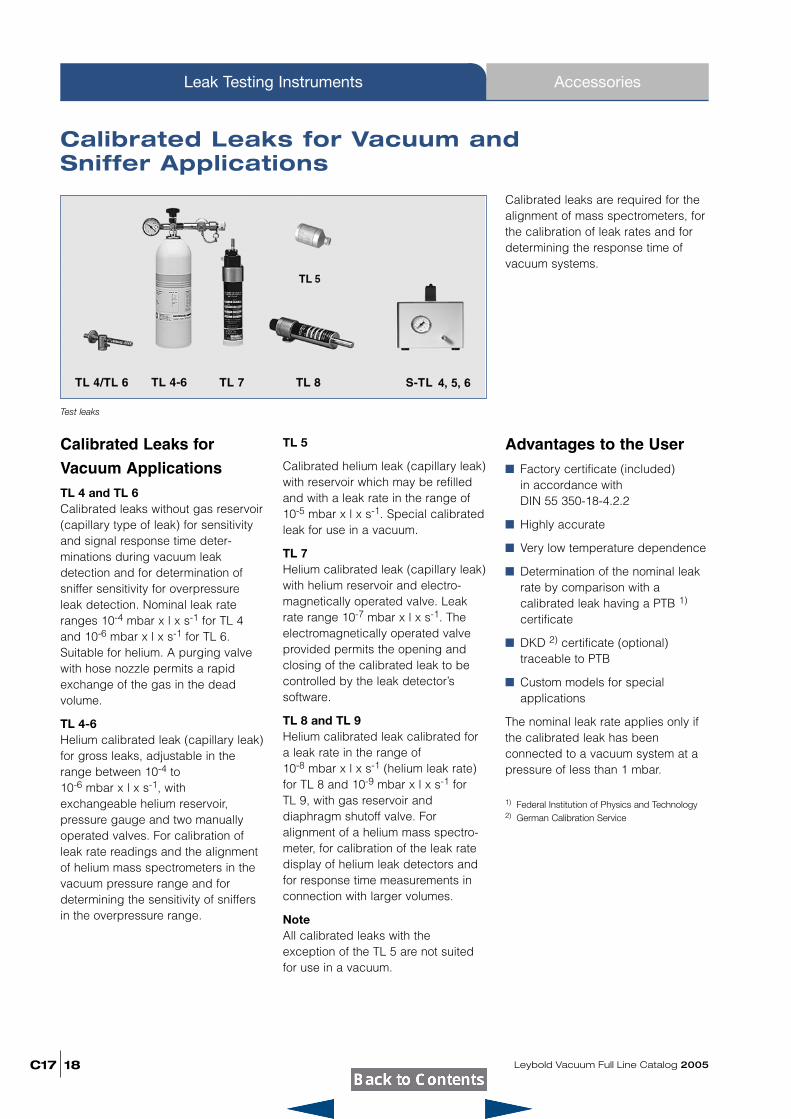
Calibrated Leaks for Vacuum and Sniffer Applications
Calibrated Leaks for
Vacuum ApplicationsTL 4 and TL 6Calibrated leaks without gas reservoir(capillary type of leak) for sensitivityand signal response time deter-minations during vacuum leakdetection and for determination ofsniffer sensitivity for overpressureleak detection. Nominal leak rateranges 10-4 mbar x l x s-1 for TL 4and 10-6 mbar x l x s-1 for TL 6.Suitable for helium. A purging valvewith hose nozzle permits a rapidexchange of the gas in the deadvolume.
TL 4-6Helium calibrated leak (capillary leak)for gross leaks, adjustable in therange between 10-4 to 10-6 mbar x l x s-1, withexchangeable helium reservoir,pressure gauge and two manuallyoperated valves. For calibration ofleak rate readings and the alignmentof helium mass spectrometers in thevacuum pressure range and fordetermining the sensitivity of sniffersin the overpressure range.
TL 5
Calibrated helium leak (capillary leak)with reservoir which may be refilledand with a leak rate in the range of10-5 mbar x l x s-1. Special calibratedleak for use in a vacuum.
TL 7Helium calibrated leak (capillary leak)with helium reservoir and electro-magnetically operated valve. Leakrate range 10-7 mbar x l x s-1. Theelectromagnetically operated valveprovided permits the opening andclosing of the calibrated leak to becontrolled by the leak detector’ssoftware.
TL 8 and TL 9Helium calibrated leak calibrated fora leak rate in the range of 10-8 mbar x l x s-1 (helium leak rate)for TL 8 and 10-9 mbar x l x s-1 for TL 9, with gas reservoir anddiaphragm shutoff valve. Foralignment of a helium mass spectro-meter, for calibration of the leak ratedisplay of helium leak detectors andfor response time measurements inconnection with larger volumes.
NoteAll calibrated leaks with theexception of the TL 5 are not suitedfor use in a vacuum.
Advantages to the User� Factory certificate (included)
in accordance with DIN 55 350-18-4.2.2
� Highly accurate
� Very low temperature dependence
� Determination of the nominal leakrate by comparison with acalibrated leak having a PTB 1)
certificate
� DKD 2) certificate (optional)traceable to PTB
� Custom models for specialapplications
The nominal leak rate applies only ifthe calibrated leak has beenconnected to a vacuum system at apressure of less than 1 mbar.
1) Federal Institution of Physics and Technology2) German Calibration Service
Calibrated leaks are required for thealignment of mass spectrometers, forthe calibration of leak rates and fordetermining the response time ofvacuum systems.
Test leaks
Cal ibrated LeakOrdering Information
Leybold Vacuum Full Line Catalog 2005 C17
Accessories Leak Testing Instruments
19
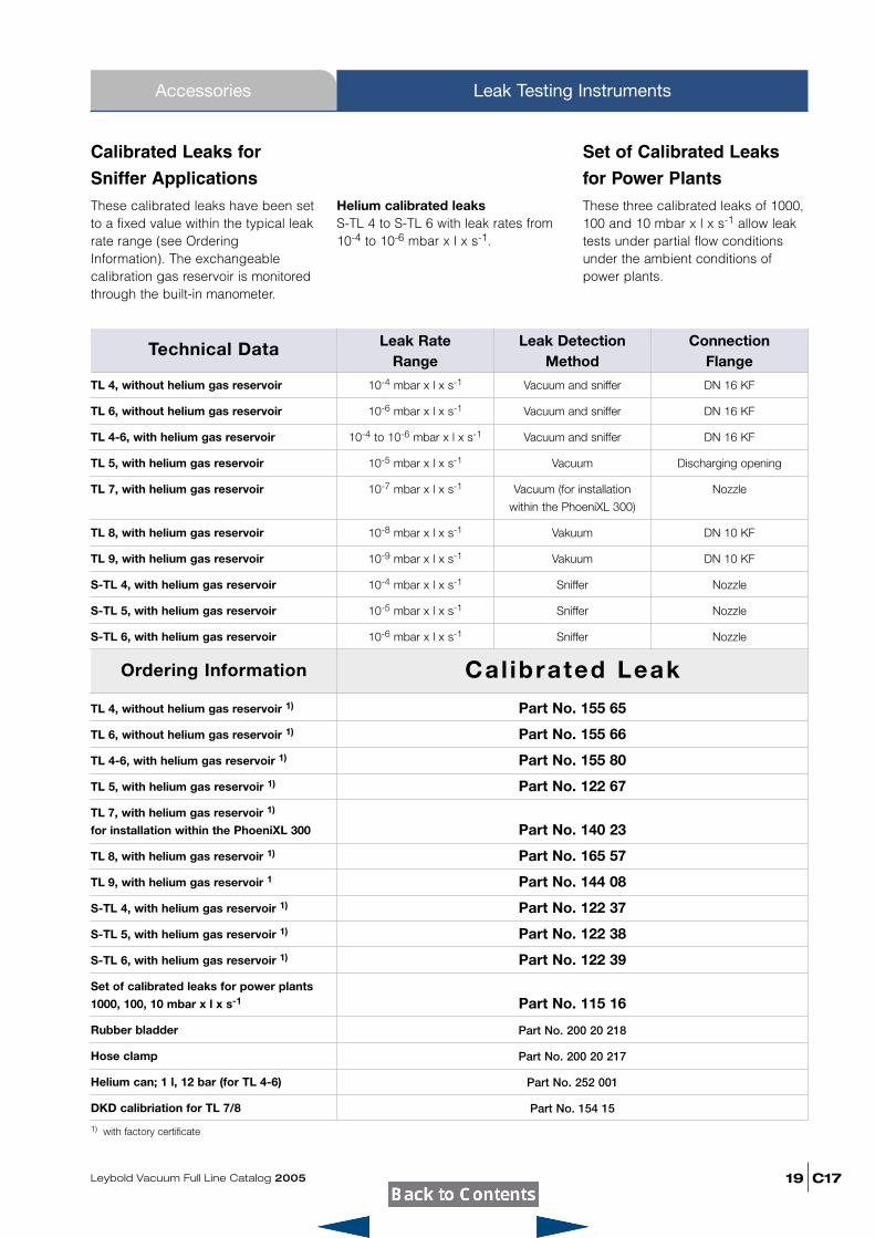
Technical Data
TL 4, without helium gas reservoir
TL 6, without helium gas reservoir
TL 4-6, with helium gas reservoir
TL 5, with helium gas reservoir
TL 7, with helium gas reservoir
TL 8, with helium gas reservoir
TL 9, with helium gas reservoir
S-TL 4, with helium gas reservoir
S-TL 5, with helium gas reservoir
S-TL 6, with helium gas reservoir
10-4 mbar x l x s-1 Vacuum and sniffer DN 16 KF
10-6 mbar x l x s-1 Vacuum and sniffer DN 16 KF
10-4 to 10-6 mbar x l x s-1 Vacuum and sniffer DN 16 KF
10-5 mbar x l x s-1 Vacuum Discharging opening
10-7 mbar x l x s-1 Vacuum (for installation Nozzle
within the PhoeniXL 300)
10-8 mbar x l x s-1 Vakuum DN 10 KF
10-9 mbar x l x s-1 Vakuum DN 10 KF
10-4 mbar x l x s-1 Sniffer Nozzle
10-5 mbar x l x s-1 Sniffer Nozzle
10-6 mbar x l x s-1 Sniffer Nozzle
Leak Rate Range
Leak DetectionMethod
Connection Flange
TL 4, without helium gas reservoir 1)
TL 6, without helium gas reservoir 1)
TL 4-6, with helium gas reservoir 1)
TL 5, with helium gas reservoir 1)
TL 7, with helium gas reservoir 1)
for installation within the PhoeniXL 300
TL 8, with helium gas reservoir 1)
TL 9, with helium gas reservoir 1
S-TL 4, with helium gas reservoir 1)
S-TL 5, with helium gas reservoir 1)
S-TL 6, with helium gas reservoir 1)
Set of calibrated leaks for power plants
1000, 100, 10 mbar x l x s-1
Rubber bladder
Hose clamp
Helium can; 1 l, 12 bar (for TL 4-6)
DKD calibriation for TL 7/8
1) with factory certificate
Part No. 155 65
Part No. 155 66
Part No. 155 80
Part No. 122 67
Part No. 140 23
Part No. 165 57
Part No. 144 08
Part No. 122 37
Part No. 122 38
Part No. 122 39
Part No. 115 16
Part No. 200 20 218
Part No. 200 20 217
Part No. 252 001
Part No. 154 15
Calibrated Leaks for
Sniffer ApplicationsThese calibrated leaks have been setto a fixed value within the typical leakrate range (see OrderingInformation). The exchangeablecalibration gas reservoir is monitoredthrough the built-in manometer.
Helium calibrated leaksS-TL 4 to S-TL 6 with leak rates from10-4 to 10-6 mbar x l x s-1.
Set of Calibrated Leaks
for Power PlantsThese three calibrated leaks of 1000,100 and 10 mbar x l x s-1 allow leaktests under partial flow conditionsunder the ambient conditions ofpower plants.
C17
Accessories
Leybold Vacuum Full Line Catalog 200520
Leak Testing Instruments
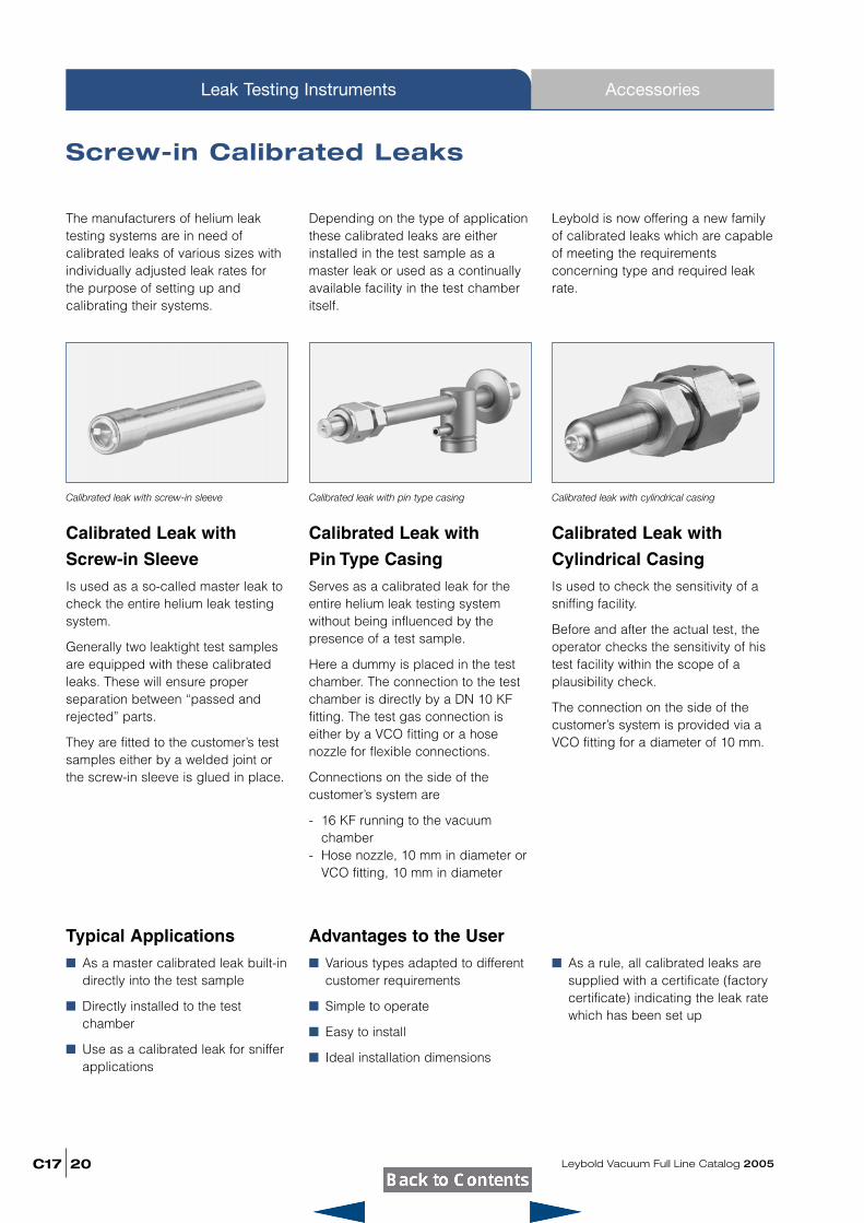
Screw-in Calibrated Leaks
Calibrated Leak with
Screw-in SleeveIs used as a so-called master leak tocheck the entire helium leak testingsystem.
Generally two leaktight test samplesare equipped with these calibratedleaks. These will ensure proper separation between “passed andrejected” parts.
They are fitted to the customer’s testsamples either by a welded joint orthe screw-in sleeve is glued in place.
Calibrated Leak with
Pin Type CasingServes as a calibrated leak for theentire helium leak testing systemwithout being influenced by the presence of a test sample.
Here a dummy is placed in the testchamber. The connection to the testchamber is directly by a DN 10 KF fitting. The test gas connection is either by a VCO fitting or a hosenozzle for flexible connections.
Connections on the side of the customer’s system are
- 16 KF running to the vacuumchamber
- Hose nozzle, 10 mm in diameter orVCO fitting, 10 mm in diameter
Calibrated Leak with
Cylindrical CasingIs used to check the sensitivity of asniffing facility.
Before and after the actual test, theoperator checks the sensitivity of histest facility within the scope of a plausibility check.
The connection on the side of thecustomer’s system is provided via aVCO fitting for a diameter of 10 mm.
Depending on the type of applicationthese calibrated leaks are eitherinstalled in the test sample as amaster leak or used as a continuallyavailable facility in the test chamberitself.
Calibrated leak with screw-in sleeve
The manufacturers of helium leaktesting systems are in need of calibrated leaks of various sizes withindividually adjusted leak rates forthe purpose of setting up and calibrating their systems.
Leybold is now offering a new familyof calibrated leaks which are capableof meeting the requirements concerning type and required leakrate.
Calibrated leak with pin type casing Calibrated leak with cylindrical casing
Typical Applications� As a master calibrated leak built-in
directly into the test sample
� Directly installed to the test chamber
� Use as a calibrated leak for sniffer applications
Advantages to the User� Various types adapted to different
customer requirements
� Simple to operate
� Easy to install
� Ideal installation dimensions
� As a rule, all calibrated leaks aresupplied with a certificate (factorycertificate) indicating the leak ratewhich has been set up
Ordering Information 1)
Leybold Vacuum Full Line Catalog 2005 C17
Accessories Leak Testing Instruments
21
Technical Data
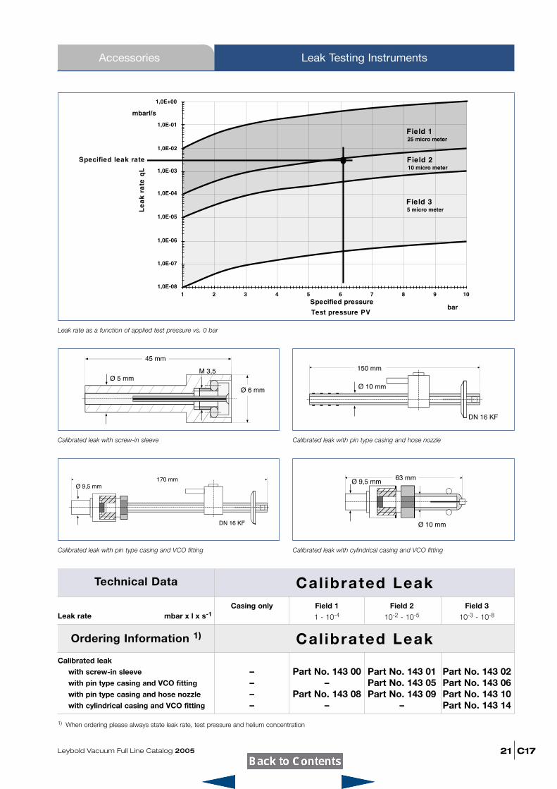
Leak rate mbar x l x s-1Casing only Field 1 Field 2 Field 3
1 - 10-4 10-2 - 10-5 10-3 - 10-8
Cal ibrated Leak
Calibrated leak
with screw-in sleeve
with pin type casing and VCO fitting
with pin type casing and hose nozzle
with cylindrical casing and VCO fitting
– Part No. 143 00 Part No. 143 01 Part No. 143 02– – Part No. 143 05 Part No. 143 06– Part No. 143 08 Part No. 143 09 Part No. 143 10– – – Part No. 143 14
Cal ibrated Leak
1) When ordering please always state leak rate, test pressure and helium concentration
Leak rate as a function of applied test pressure vs. 0 bar
Calibrated leak with screw-in sleeve Calibrated leak with pin type casing and hose nozzle
Calibrated leak with pin type casing and VCO fitting Calibrated leak with cylindrical casing and VCO fitting
C17
AccessoriesLeak Testing Instruments
Leybold Vacuum Full Line Catalog 200522
Accessories for the PhoeniXL 300,PhoeniXL 300 Dry and PhoeniXL 300 Modul
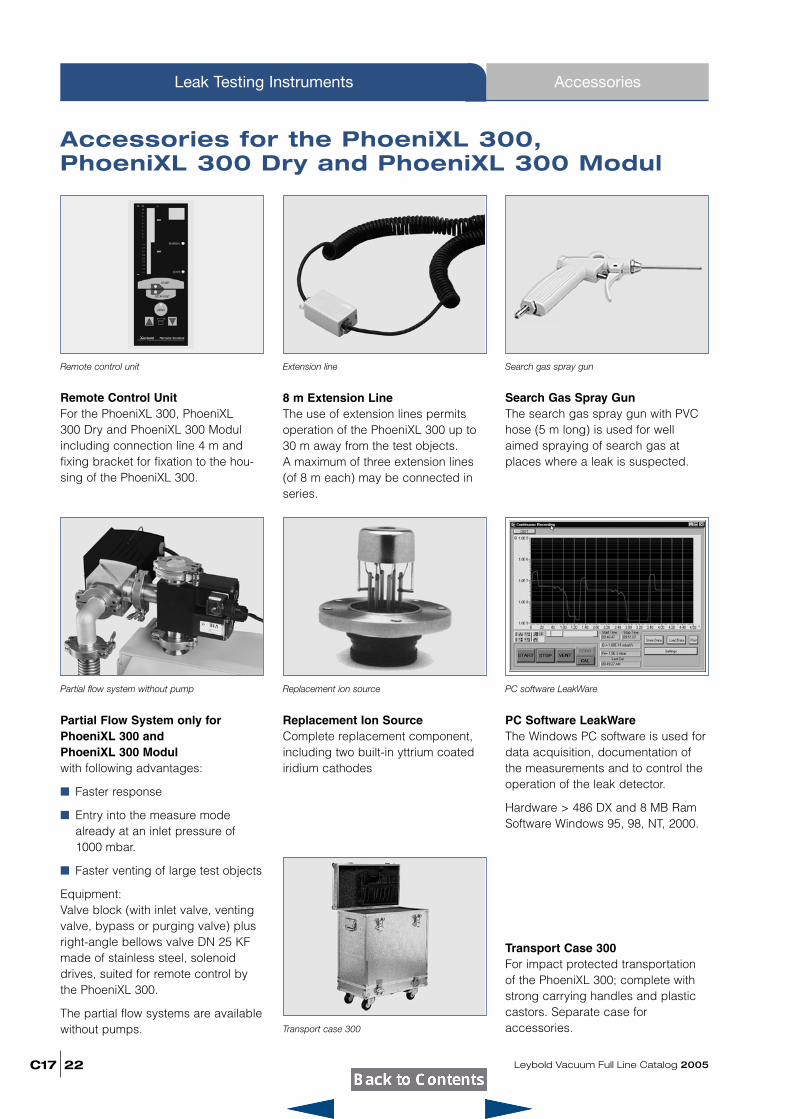
Remote Control UnitFor the PhoeniXL 300, PhoeniXL 300 Dry and PhoeniXL 300 Modulincluding connection line 4 m andfixing bracket for fixation to the hou-sing of the PhoeniXL 300.
Search Gas Spray GunThe search gas spray gun with PVChose (5 m long) is used for wellaimed spraying of search gas at places where a leak is suspected.
Remote control unit Search gas spray gun
Partial Flow System only forPhoeniXL 300 and PhoeniXL 300 Modulwith following advantages:
� Faster response
� Entry into the measure modealready at an inlet pressure of1000 mbar.
� Faster venting of large test objects
Equipment:Valve block (with inlet valve, ventingvalve, bypass or purging valve) plusright-angle bellows valve DN 25 KFmade of stainless steel, solenoiddrives, suited for remote control bythe PhoeniXL 300.
The partial flow systems are availablewithout pumps.
Replacement Ion SourceComplete replacement component,including two built-in yttrium coatediridium cathodes
8 m Extension LineThe use of extension lines permitsoperation of the PhoeniXL 300 up to30 m away from the test objects. A maximum of three extension lines(of 8 m each) may be connected inseries.
Partial flow system without pump Replacement ion source
Extension line
PC Software LeakWareThe Windows PC software is used fordata acquisition, documentation ofthe measurements and to control theoperation of the leak detector.
Hardware > 486 DX and 8 MB RamSoftware Windows 95, 98, NT, 2000.
PC software LeakWare
Transport Case 300For impact protected transportationof the PhoeniXL 300; complete withstrong carrying handles and plasticcastors. Separate case foraccessories.Transport case 300
Leybold Vacuum Full Line Catalog 2005 C17
Accessories Leak Testing Instruments
23
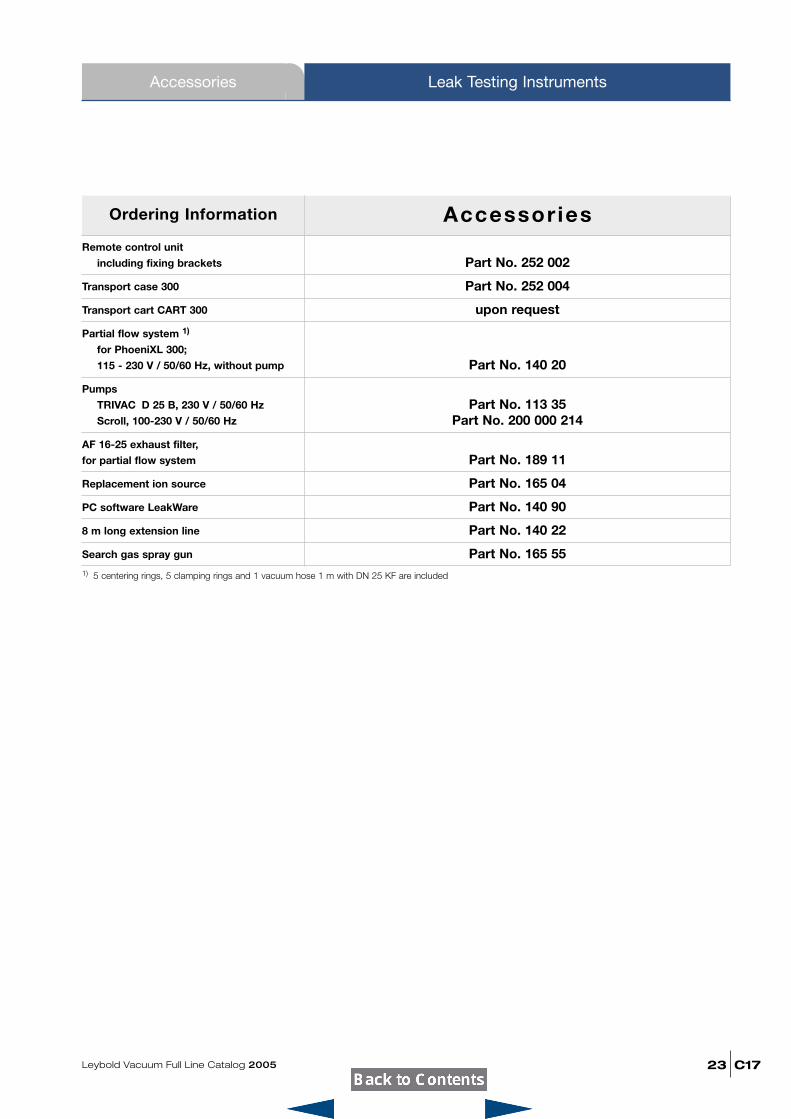
Ordering Information
Remote control unit
including fixing brackets
Transport case 300
Transport cart CART 300
Partial flow system 1)
for PhoeniXL 300;
115 - 230 V / 50/60 Hz, without pump
Pumps
TRIVAC D 25 B, 230 V / 50/60 Hz
Scroll, 100-230 V / 50/60 Hz
AF 16-25 exhaust filter,
for partial flow system
Replacement ion source
PC software LeakWare
8 m long extension line
Search gas spray gun
1) 5 centering rings, 5 clamping rings and 1 vacuum hose 1 m with DN 25 KF are included
Part No. 252 002
Part No. 252 004
upon request
Part No. 140 20
Part No. 113 35Part No. 200 000 214
Part No. 189 11
Part No. 165 04
Part No. 140 90
Part No. 140 22
Part No. 165 55
Accessories
C17
Accessories
Leybold Vacuum Full Line Catalog 200524
Leak Testing Instruments
Helium Sample Probes (Sniffers)
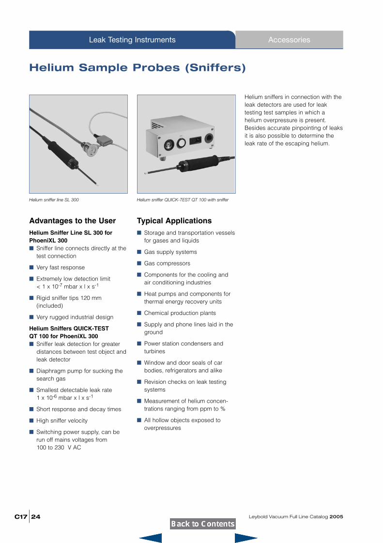
Advantages to the UserHelium Sniffer Line SL 300 forPhoeniXL 300� Sniffer line connects directly at the
test connection
� Very fast response
� Extremely low detection limit< 1 x 10⁻⁷ mbar x l x s-1
� Rigid sniffer tips 120 mm(included)
� Very rugged industrial design
Helium Sniffers QUICK-TEST QT 100 for PhoeniXL 300� Sniffer leak detection for greater
distances between test object andleak detector
� Diaphragm pump for sucking thesearch gas
� Smallest detectable leak rate 1 x 10⁻⁶ mbar x l x s-1
� Short response and decay times
� High sniffer velocity
� Switching power supply, can berun off mains voltages from 100 to 230 V AC
Typical Applications� Storage and transportation vessels
for gases and liquids
� Gas supply systems
� Gas compressors
� Components for the cooling andair conditioning industries
� Heat pumps and components forthermal energy recovery units
� Chemical production plants
� Supply and phone lines laid in theground
� Power station condensers andturbines
� Window and door seals of carbodies, refrigerators and alike
� Revision checks on leak testingsystems
� Measurement of helium concen-trations ranging from ppm to %
� All hollow objects exposed tooverpressures
Helium sniffers in connection with theleak detectors are used for leaktesting test samples in which a helium overpressure is present.Besides accurate pinpointing of leaksit is also possible to determine theleak rate of the escaping helium.
Helium sniffer line SL 300 Helium sniffer QUICK-TEST QT 100 with sniffer
QT 100SL 300Ordering Information
Leybold Vacuum Full Line Catalog 2005 C17
Accessories Leak Testing Instruments
25
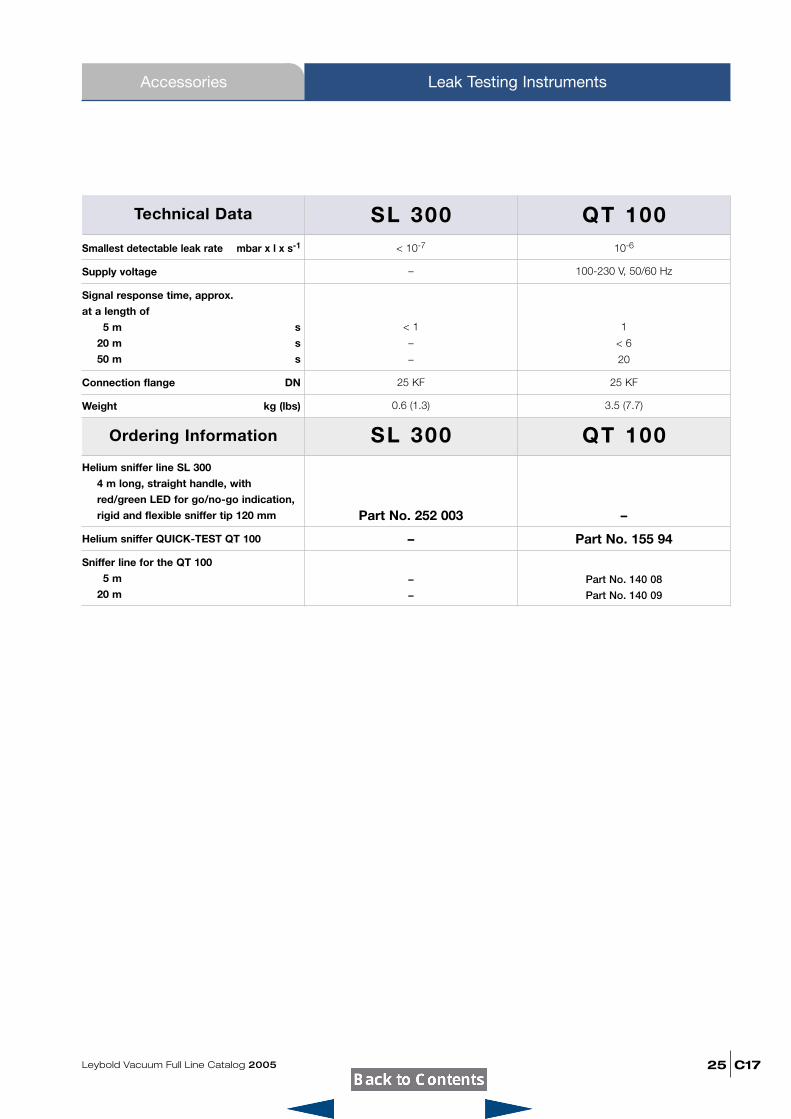
Technical Data
Smallest detectable leak rate mbar x l x s-1
Supply voltage
Signal response time, approx.
at a length of
05 m s
20 m s
50 m s
Connection flange DN
Weight kg (lbs)
< 10-7 10-6
– 100-230 V, 50/60 Hz
< 1 1
– < 6
– 20
25 KF 25 KF
0.6 (1.3) 3.5 (7.7)
Helium sniffer line SL 300
4 m long, straight handle, with
red/green LED for go/no-go indication,
rigid and flexible sniffer tip 120 mm
Helium sniffer QUICK-TEST QT 100
Sniffer line for the QT 100
05 m
20 m
Part No. 252 003 –
– Part No. 155 94
– Part No. 140 08
– Part No. 140 09
SL 300 QT 100
C17
Accessories
Leybold Vacuum Full Line Catalog 200526
Leak Testing Instruments
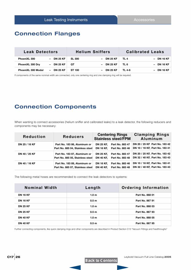
Leak Detectors Hel ium Sniffers Cal ibrated Leaks
PhoeniXL 300 – DN 25 KF
PhoeniXL 300 Dry – DN 25 KF
PhoeniXL 300 Modul – DN 25 KF
If components of the same nominal width are connected, only one centering ring and one clamping ring will be required.
SL 300 – DN 25 KF
QT – DN 25 KF
ST 100 – DN 25 KF
TL 4 – DN 16 KF
TL 6 – DN 16 KF
TL 4-6 – DN 16 KF
Connection Flanges
Connection Components
When wanting to connect accessories (helium sniffer and calibrated leaks) to a leak detector, the following reducers andcomponents may be necessary:
Reduct ion Reducers Centering RingsStainless steel/FPM
Clamping RingsAluminum
DN 25 / 16 KF
DN 40 / 25 KF
DN 40 / 16 KF
Part No. 183 86, Aluminum or
Part No. 885 04, Stainless steel
Part No. 183 87, Aluminum or
Part No. 885 05, Stainless steel
Part No. 183 89, Aluminum or
Part No. 885 07, Stainless steel
DN 25 KF, Part No. 883 47
DN 16 KF, Part No. 883 46
DN 25 KF, Part No. 883 47
DN 40 KF, Part No. 883 48
DN 16 KF, Part No. 883 46
DN 40 KF, Part No. 883 48
DN 20 / 25 KF Part No. 183 42
DN 10 / 16 KF, Part No. 183 41
DN 20 / 25 KF, Part No. 183 42
DN 32 / 40 KF, Part No. 183 43
DN 10 / 16 KF, Part No. 183 41
DN 32 / 40 KF, Part No. 183 43
The following metal hoses are recommended to connect the leak detectors to systems:
Nominal Width Length Order ing Information
DN 16 KF
DN 16 KF
DN 25 KF
DN 25 KF
DN 40 KF
DN 40 KF
Further connecting components, like quick clamping rings and other components are described in Product Section C13 “Vacuum Fittings and Feedthroughs”
1.0 m
0.5 m
1.0 m
0.5 m
1.0 m
0.5 m
Part No. 868 01
Part No. 867 91
Part No. 868 03
Part No. 867 93
Part No. 868 05
Part No. 867 95
Leybold Vacuum Full Line Catalog 2005 C17
Leak Testing Instruments
27
Notes
vacuumLeybold Vacuum GmbHBonner Strasse 498D-50968 ColognePhone: +49-221 347-0Fax: +49-221 [email protected] w w w . l e y b o l d . c o m
P.R. China
Leybold Vacuum (Tianjin) International Trade Co., Ltd.Beichen Economic Development Area (BEDA),No. 8 Western Shuangchen RoadTianjin 300400, ChinaSales and Service:Phone: +86-22-2697 0808Fax: +86-22-2697 4061Fax: +86-22-2697 [email protected]
Leybold Vacuum (Tianjin)Equipment Manufacturing Co., Ltd.Beichen Economic Development Area (BEDA),No. 8 Western Shuangchen RoadTianjin 300400, ChinaPhone: +86-22-2697 0808Fax: +86-22-2697 4061Fax: +86-22-2697 [email protected]
Leybold Vacuum (Tianjin) International Trade Co., Ltd.Beijing Branch:1-908, Beijing Landmark Towers8 North Dongsanhuan RoadChaoyang DistrictBeijing 100004, ChinaSales and Service:Phone: +86-10-6590-7607Fax: +86-10-6590-7622
Leybold Vacuum (Tianjin) International Trade Co., Ltd.Shanghai Branch:Add: No. 33, 76 Futedong SanRd., Waigaoqiao FTZ , Shanghai 200131, ChinaSales and Service:Phone: +86-21-5064-4666Fax: [email protected]
Leybold Vacuum (Tianjin)Guangzhou Branch:Add: G/F,#301 Building, 110 Dongguangzhuang Rd.Tianhe District, Guangzhou 510610, ChinaSales:Phone: +86-20-8723-7873Phone: +86-20-8723-7597Fax: [email protected]
India
Leybold Vacuum India Pvt Ltd.A-215 Road No. 30MIDC Wagle Industrial EstateThane(W) - 400 604 MaharashtraIndiaSales and Service:Phone: +91-22-2581 2929Fax: +91-22-2581 [email protected]
Netherlands
Leybold Vacuum Nederland B.V.Computerweg 7NL-3542 DP UtrechtSales and Service: Phone: +31-346-58 39 99 Fax: +31-346-58 39 90 [email protected]@leybold.com
Spain
Leybold Vacuum España S.A.C/. Huelva, 7E-08940 Cornella de Llobregat (Barcelona)Sales: Phone: +34-93-666 46 16Fax: +34-93-666 43 [email protected] Service: Phone: +34-93-666 49 51Fax: +34-93-685 40 10
Sweden
Leybold Vacuum Scandinavia ABBox 9084SE-40092 GöteborgSales and Service: Phone: +46-31-68 84 70 Fax: +46-31-68 39 39 [email protected]/delivery address:Datavägen 57BSE-43632 Askim
Switzerland
Leybold Vacuum Schweiz AGLeutschenbachstrasse 55CH-8050 ZürichSales: Phone: +41-1-308 40 50 Fax: +41-1-302 43 73 [email protected]: Phone: +41-1-308 40 62 Fax: +41-1-308 40 60
USA
Leybold Vacuum USA Inc.5700 Mellon RoadExport, PA [email protected]: Eastern & Central time zonesPhone: +1-724-327-5700Fax: +1-724-733-1217Pacific, Mountain, Alaskan & Hawaiian time zonesPhone: +1-480-752-9191Fax: +1-480-752-9494Service: Phone: +1-724-327-5700Fax: +1-724-733-3799
Belgium
Leybold Vacuum Nederland B.V.Belgisch bijkantoorLeuvensesteenweg 542-9AB-1930 ZaventemSales: Phone: +32-2-711 00 83 Fax: +32-2-720 83 38 [email protected]: Phone: +32-2-711 00 82 Fax: +32-2-720 83 38 [email protected]
France
Leybold Vacuum France S.A.7, Avenue du QuébecZ.A. de Courtaboeuf, B.P. 42F-91942 Courtaboeuf CedexSales and Service: Phone: +33-1-69 82 48 00 Fax: +33-1-69 07 57 38 [email protected]
Leybold Vacuum France S.A.Valence Factory640, Rue A. Bergès - B.P. 107 F-26501 Bourg-lès-Valence CedexPhone: +33-4-75 82 33 00 Fax: +33-4-75 82 92 69 [email protected]
Great Britain
Leybold Vacuum UK Ltd.Waterside Way, Plough LaneGB-London SW17 0HBSales: Phone: +44-20-8971 7000 Fax: +44-20-8971 7001 [email protected]: Phone: +44-20-8971 7030 Fax: +44-20-8971 7003 [email protected]
Italy
Leybold Vacuum Italia S.p.A.8, Via Trasimeno I-20128 MilanoSales: Phone: +39-02-27 22 31 Fax: +39-02-27 20 96 41 [email protected]:Phone: +39-02-27 22 31 Fax: +39-02-27 20 96 41 [email protected]
Field Service BaseZ.I.Le CapanneI-05021 Acquasparta (TR)Phone: +39-0744-93 03 93Fax: +39-0744-94 42 [email protected]
Leybold Vacuum GmbHBonner Strasse 498 D-50968 ColognePhone: +49-221-347 1234 Fax: +49-221-347 1245 [email protected]
Leybold Vacuum GmbHSales Area North/EastBranch office BerlinBuschkrugallee 331. ObergeschossD-12359 BerlinPhone: +49-30-435 609 0 Fax: +49-30-435 609 10 [email protected]
Leybold Vacuum GmbHSales Area South/SouthwestBranch office MunicKarl-Hammerschmidt-Strasse 38D-85609 Aschheim/DornachPhone: +49-89-357 33 90 Fax: +49-89-357 33 933 [email protected]@leybold.com
Leybold Vacuum GmbHSales Area WestBranch office CologneEmil-Hoffmann-Straße 43D-50996 Cologne-SuerthPhone: +49-221-347 1270 Fax: +49-221-347 1291 [email protected]
Leybold Vacuum GmbHService CenterEmil-Hoffmann-Straße 43D-50996 Cologne-SuerthPhone: +49-221-347 1439 Fax: +49-221-347 1945 [email protected]
Leybold Vacuum GmbHMobile after sales serviceEmil-Hoffmann-Straße 43 D-50996 Cologne-SuerthPhone: +49-221-347 1765 Fax: +49-221-347 1944 [email protected]
Leybold Vacuum Dresden GmbHZur Wetterwarte 50, Haus 304D-01109 DresdenService: Phone: +49-351-88 55 00 Fax: +49-351-88 55 041 [email protected]
Japan
Leybold Vacuum Japan Co., Ltd.Head OfficeTobu A.K. Bldg. 4th Floor23-3, Shin-Yokohama 3-chomeKohoku-ku, Yokohama-shiKanagawa-ken 222-0033Sales:Phone: +81-45-4713330Fax: +81-45-4713323
Leybold Vacuum Japan Co., Ltd.Osaka Branch OfficeMURATA Bldg. 7F2-7-53, Nihi-MiyaharaYodogawa-ku Osaka-shi 532-0004Sales:Phone: +81-6-6393-5211Fax: +81-6-6393-5215
Leybold Vacuum Japan Co., Ltd.Tsukuba Technical S.C.Tsukuba Minami Daiichi Kogyo Danchi21, Kasumi-no-Sato, Ami-machi, Inashiki-gunIbaraki-ken, 300-0315Service:Phone: +81-298-89-2841Fax: +81-298-89-2838
Korea
Leybold Vacuum Korea Ltd.#761-4, Yulkeum-ri,SungHwan-eup, Cheonan-CityChoongchung-Namdo,330-807, KoreaSales:Phone: +82-41-580-4420Fax: +82-41-588-3737Service:Phone: +82-41-580-4415Fax: +82-41-588-3737
Singapore
Leybold Vacuum Singapore Pte Ltd.No.1, International Business Park,B1-20B, The SynergySingapore 609917Sales and Service:Phone: +65-66652910Fax: [email protected]
Taiwan
Leybold Vacuum Taiwan Ltd.No 416-1, Sec. 3Chung-Hsin Rd., Chu-TungHsin-Chu, Taiwan, R.O.C.Sales and Service:Phone: +886-3-5833988Fax: +886-3-5833999
Germany Europe Asia
America
HotlineSales: +49-221-347 1234Service: +49-221-347 [email protected]@leybold.com
LV_0
7324
_200
5
05
.05
Sales and Service Net Worldwide