Layman's Guide to Microphone Specifications Column ...RADIO-TV EXPERIMENTER "Assembling the Scott...
78
the authoritative magazine about 'igh fidelity STEREO EQUIPMENT & RECORD REVIEWS AUGUST 1969 60 e Layman's Guide to Microphone Specifications Column Loudspeaker Systems How Stereo FM Works www.americanradiohistory.com AmericanRadioHistory.Com
Transcript of Layman's Guide to Microphone Specifications Column ...RADIO-TV EXPERIMENTER "Assembling the Scott...

the authoritative magazine about 'igh fidelity
STEREO EQUIPMENT & RECORD REVIEWS
AUGUST 1969 60 e
Layman's Guide to Microphone Specifications
Column Loudspeaker Systems How Stereo FM Works
www.americanradiohistory.comAmericanRadioHistory.Com

America's Top Rated Kits Now a Best Buy!*
TOP RATED BY POPULAR SCIENCE "... How does it perform? In a word, flawlessly, stereo performance is su- perb, and the set's sensitivity will cope with the deepest fringe -area reception conditions. The tuner has no automatic frequency control, and doesn't need one, since drift is nonexistent. I rate the LT -112B as one of the finest FM tun- ers available - in or out of kit form." TOP RATED BY HI FI/STEREO REVIEW "We measured the IHF sensitivity of the Scott LT -112B tuner as 1.4 micro- volts, which certainly makes it one of the most sensitive tuners we have en- countered ... The Scott LT -112B kit is a real buy at $199.95*and it would be hard to surpass its performance at any price." TOP RATED BY AMERICAN RECORD GUIDE "I would recommend this kit for the beginner if only because of the man- ual's excellence and completeness .. .
Let me summarize by saying that the Scott LT -112B tuner must be placed in the very top echelon of today's com- ponents. It is easy to build and even easier to listen to." TOP RATED BY AUDIO "Here's a stereo FM/ AM receiver kit with a real hot front end, fairly high
power output, low distortion, and ex- cellent operating flexibility. Besides that, it's a good-looking unit when as- sembled; no `kit look' to this one. And assembling it yourself saves money. All in all, if kit building is your forte (or even if you've never tried it for fear
. of possible complexity), the Scott LR - 88 offers a most competent design at a price well below that for an equivalent factory -assembled unit." TOP RATED BY ELECTRONICS ILLUSTRATED "One of the finest examples of solid- state integrated -amplifier kit design, packaging and performance we have seen is the Scott LK-60. The LK-60 has practically every operating feature you'd want ... performance left little to be desired." "In a nutshell, the manual is the most complete, fool -proof one we've seen in a long time. The only thing Scott didn't do is include a technician to build the kit."
TOP RATED BY HIGH FIDELITY "... an unprecedented high sensitivity, one which surprised even us and which, incidentally, does make a difference in the number of stations received and the clarity with which they come in. This is certainly a tuner for use in the most difficult of reception areas; stations seem to pop in all across the tuner dial."
Write for complete details:
CSCOTT®
TOP RATED BY RADIO-TV EXPERIMENTER "Assembling the Scott LK-60 is the next best thing to buying it wired as it's not really a kit - it's a semi -kit. The really critical, difficult, and no- tably boring chore of assembling the printed circuit boards used for the preamps, tone controls, and output drivers is done at the factory. All the user does is connect the appropriate connecting leads to the printed circuit boards. The heat sinks and their com- ponents, used for the output transis- tors, are also factory assembled."
New computerized design and assembly techniques now
make possible the latest improvement in Scott kits...
a lower price!
LT -112B-1 FM Stereo Monitor Tuner Kit:
Now $149.95 LK-60B 160 -Watt Stereo
Amplifier Kit: Now $149.95
LR -88 135 -Watt AM/FM Stereo Receiver Kit:
Now $299.95
H.H. Scott, Inc., Maynard, Massachusetts 01754 Export: Scott International, Maynard, Mass. 01754 ©1969, H. H. Scott, Inc.
Check No. 100 on Reader Service Card
www.americanradiohistory.comAmericanRadioHistory.Com
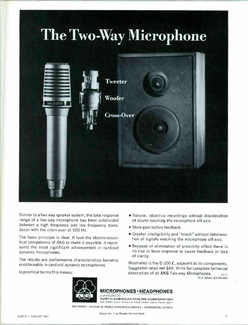
Similar to a two-way speaker system, the total response range of a two-way microphone has been subdivided between a high frequency and low frequency trans- ducer with the cross -over at 500 Hz.
The basic principle is ideal. It took the electro -acous- tical competence of AKG to make it possible. It repre- sents the most significant advancement in cardioid dynamic microphones.
The results are performance characteristics formerly unobtainable in cardioid dynamic microphones.
In practical terms this means:
Natural, objective recordings without discoloration of sound reaching the microphone off -axis.
More gain before feedback.
Greater intelligibility and "reach" without deteriora- tion of signals reaching the microphone off -axis.
Because of elimination of proximity effect there is no rise in bass response to cause feedback or loss of clarity.
Illustrated is the D 200 E, adjacent to its components. Suggested retail net $69. Write for complete technical description of all AKG Two-way Microphones. .Na.29
*U.S. Patent #3,204,031
MICROPHONES HEADPHONES DISTRIBUTED BY
NORTH AMERICAN PHILIPS CORPORATION 100 EAST 42nd STREET, NEW YORK, NEW YORK 10017
AKG CANADA DIVISION OF DOUBLE DIAMOND ELECTRONICS SCARBOROUGH, ONTARIO
Check No. 1 on Reader Service Card AUDIO AUGUST 1969 1
www.americanradiohistory.comAmericanRadioHistory.Com

August 1969 Vol. 53, No. 8
Number 71 in a series of discussions by Electro -Voice engineers
JIM LONG Marketing Manager Commercial Products
Upgrading a successful product to take full advantage of present technology is always an interesting challenge to the design engi- neer. Any alterations must provide clear benefits to the user and/or advantages in production efficiency in order to offset the costs of the changes. A case in point is the new Electro -Voice Musicaster IA*. This indoor/outdoor wide - range PA speaker has found wide applica- tion where extended response is required for both voice and music at high efficiency in a modest size. In this redesign effort, only the basic con- cept remained untouched. New advances in molding glass -filled polyester permitted uni- form thin -wall construction that saved over 2 lbs. compared with the original aluminum die-cast enclosure. Strength and rigidity were undiminished by the change. The new material possesses much higher internal damping than the original aluminum cast- ing, thus improving system transient and frequency response. Speaker size has been increased from 8" to 12" with a notable improvement in low fre- quency'range and response uniformity. To further smooth overall response, the Musi - caster IA interior is filled with fiberglass and the peripheral ducted ports from the origi- nal design have been retained. Silicone treatment of the cone aids in resist- ing the effects of moisture. In addition, the speaker is now protected by a 1/4" thick Acoustifoam* weather barrier behind the grille screen. This unusual open -cell foam plastic sheeting is virtually transparent to sound, yet its small cell construction effec- tively bars water droplets from entering, even when driven by relatively high winds. In addition to the functional changes to improve performance and reliability, ap- pearance changes were made to create a contemporary style more in tune with to- day's architectural trends. The result of these changes has been to create an entirely new speaker system that retains the basic advantages of the original Musicaster while providing better perfor- mance and easier installation at lower cost to the user. * Electro -Voice trademark
For reprints of other discussions In this series, or technical data on any E -V product, write:
ELECTRO -VOICE, INC., Dept. 893 A
602 Cecil St., Buchanan, Michigan 49107
5&cee- A SUBSIDIARY OF GULTON INDUSTRIES, INC.
AUDIO Successor to RAI. J Est 1911
ARTHUR P. SALSBERG, Editor C. G. McPRouD, Publisher EDWARD TATNALL CANBY, Associate Editor
JOHN HUBBARD RICHARD CLIFF Art Director Design
Contributing Editors HERMAN BURSTEIN JOSEPH GIOVANELLI
LEONARD FELDMAN ALEXANDER ROSNER
BERTRAM STANLEIGH SHERWOOD L. WEINGARTEN
BERT WHYTE
FEATURE ARTICLES
Layman's Guide to Microphone Specifications A Look at Public Address Amplifiers
Column Loudspeakers Facts and Fallacies About Detailed
Sound System Equalization Primer on Sound Level Meters, Part II
ABZ's of Stereo FM-How It Works Sound and Decor Styles
GERSHAN T. THALBERG Publishing Director
SANFORD L. CAHN Marketing Director
R. KENNETH BAXTER
Production Manager JUDITH S. ZUCKER
Advertising Manager MARY CLAFFEY
Subscription Manager
20 James Long 26 Leo G. Sands 31 Victor Brociner
36 Don Davis 42 Bernard Katz 46 Leonard Feldman 58
EQUIPMENT PROFILES
Marantz Loudspeaker System Shure "Hi -Track" Stereo Phono Cartridge
Allied Stereo Tape Recorder Superex Stereo Headphones
Altec Solid -State Condenser Microphone
IMTITUrI 01
HIGH FIDELITY MANVIACTUIISI
INC
50 Imperial I 51 M91E 52 TD -1070
54 ST -PRO -B 56 M50
RECORD REVIEWS
Classical 64 Edward Tatnall Canby Light Listening 68 Sherwood L. Weingarten
Jazz 72 Bertram Stanleigh
AUDIO IN GENERAL
Audioclinic What's New in Audio
Letters Behind the Scenes
Tape Guide Editor's Review
Classified Advertising Index
4 Joseph Giovanelli 8
10 12 Bert Whyte 16 Herman Burstein 18 74 76
AUDIO (title registered U. S. Pat. Off.) is published monthly by North American Publishing Co., I. J. Borowsky, President; Frank Nemeyer, C. G. McProud, Arthur Situer, and Roger Damio, Vice Presidents. Subscription rates-U. S. Possessions, Canada, and Mexico, $5.00 for one year; $9.00 for two years; all other countries, $8.00 per year. Printed in U.S.A. at Philadelphia, Pa. All rights reserved. Entire contents copyrighted 1969 by North American Publishing Co. Second class postage paid at Phila., Pa.
REGIONAL SALES OFFICES: Gershan T. Thalberg and Sanford L. Cahn, 41 East 42nd St., New York, N. Y. 10017; Telephone (212) 687-8924. Louis Weber, 5201 N. Harlem Ave., Chicago, Ill. 60656; (312) 775-0755. Jay Martin, 15010 Ventura Blvd., Sherman Oaks, Calif.; (213) 981-78.52.
REPRESENTATIVE: Matsushita Inc., 709, Kitano Arms, Hirakawa-Cho, Chiyoda-Ku Tokyo, Japan.
AUDIO Editorial and Publishing Offices, 134 N: 13th St., Philadelphia, Pa. 19107 Postmaster: Send Form 3579 to the above address.
Check No. 2 on Reader Service Card
2 Check No. 3 on Reader Service Carrie
www.americanradiohistory.comAmericanRadioHistory.Com

State of the art in automatic turntables. Be critical. Motors: 3 types -2 good -1 bettef
The Induction Motor ... most popular, least accurate. Most automatic turn- tables are built around induction mo- tors. Some are given special names (usually describing their pole structure or starting torque) . When well designed and manufactured, they have high start- ing torque ... get the platter up to full speed c uickly ... and are relatively free from rumble. But, the rotor of the in- duction motor "slips" in relation to the magnetic field and varies the motor's speed with changes in power line volt- age, turntable load and temperature. Under less than ideal conditions, as in your home, these speed changes can raise or lower not just the tempo, but the pitch of your recorded music.
The Synchramene Motor ...correct speed. incorrect c h lice. At first glance, the ideal turntable motor would seem to be the conventior-al synchronous type. This rotor never "3fips"to affect turning accuracy because I is locked in to the precise 60 -cycle frequency of the power supply. Turning speed cannot vary when voltage fluctuates ... when rocm and/or motcr temperatures change... or when record loads increase. How- ever, the corwentìonal synchronous mo- tor also ha3 its drawbacks. Starting torque and running power are often too low. And, b increase the torque and power means tco increase noise and rumble levels... tnd involl.es dispro- portionately high expense.
The Synchro-Lab MotorTM... perfect speed, perfect choice. A motor that com- bines high starting torque and synchro- nous speed accuracy has obviously been needed. The Garrard Laboratories designed the Synchro-Lab Motor to meet these needs, by combining the ad- vantages of both types of motors. This new synchronous motor reaches the cor- rect speed instantly and locks in to the 60 -cycle current ... no matter how the power line voltage varies ... or the tem- perature changes ... or how many rec- ords you play at one time. For the many people whose musical senses are easily distressed by variations in pitch, the Synchro-Lab Motor will be a constant assurance of listening pleasure.
There are, of course, other benefits which stem from the Synchro-Lab Motor, notably the elimination of the need for variable controls to obtain proper speed, and of heavy turntables which tend to cause rumble through accelerated wear on the important center bearing over a period of use in your home. The Synchro-Lab Motor powers five Garrards, priced from $59.50 to $129.50 for the SL 95 Automatic Tran- scription Turntable shown above. These units incorporate other Garrard -engineered innovations such as anti -skating compensation; cueing and pause controls; highly advanced, low -mass tonearm systems. Feature -by -feature descriptions of all models are to be found in a com- plimentary Comparator Guide. Let us send you one. Write Garrard, Dept. AK 19, Westbury, N.Y. 11590.
World's Finest
www.americanradiohistory.comAmericanRadioHistory.Com

Coming in
September Audio's Annual 1969-1970 Directory of Stereo Hi-Fi Com- ponent Equipment
Here, in one issue, you get a truly comprehensive view of what's available in
the latest hi-fi component models:
Amplifiers Preampli- fiers D Tuners D Receiv- ers D Modular Systems
Record Changers D Turntables & Tone Arms
Phono Cartridges Loudspeaker Mechanisms
Loudspeaker Systems Open -Reel Tape Re-
corders Cassette and 8 -Track Cartridge Tape Re-
corders Video Tape Recorders D Microphones
Headphones and a
host of allied products E plus a directory of manu- facturers.
In addition to this author- itative, year -long equip- ment buying guide, the September issue of AUDIO Magazine will include reg- ular features and depart- ments.
ABOUT THE COVER:
Read about the stereo equipment cabinet built by a reader to house his components and to fit in with his existing LP record rack and other furnishings on page 58.
Audio clinic JOSEPH GIOVANELLI
If you have a problem or question on audio, write to Mr. Joseph Giovanelli at AUDIO, 134 North Thirteenth Street, Philadelphia, Pa. 19107. All letters are answered. Please enclose a stamped, self-addressed envelope.
Dummy Loads
Q. This question concerns the termi- nation of transistor -type audio power amplifiers when the speakers are dis- connected.
With tube -type amplifiers, it was con- sidered essential to provide a dummy load of some sort if the amplifier was to be operated without a speaker load, in order to prevent damage to the out- put transformer.
In the case of direct -coupled transis- tor output stages, I would naturally as- sume that the same precautions should be observed. Common practice, how- ever, seems to belie this assumption. For instance, I have two such ampli- fiers which are equipped with "speaker off" switches on the front panel. In each case, the switch simply disconnects the speakers without providing any substi- tute load for the output stages. ..On the other hand, I have an auto- mobile tape cartridge player whose in- struction booklet states in large type, "Do not operate this unit with speakers disconnected, or damage to output tran- sistors may result." Please clarify this. -Bill Rasmussen, Culver, Ind.
A. Tube -equipped power amplifiers had to be operated with dummy loads when signal was fed into them because of high voltages which would otherwise be developed across the primary wind- ing of the output transformer. When the transformer's secondary is not con- nected to a load, the primary becomes a high -Q circuit having considerable in- ductance. Back voltages produced by changes in plate voltages on the output tubes would be sufficiently high to cause arcing in the tubes or breakdown of the insulation of the transformer. This is not true when the amplifier is running at very low power levels because the change in plate voltage would be very small. However, many amplifiers will be destroyed when full input voltage is
applied with no load connected to the output.
Transistors do not offer the oppor- tunity for high voltages to be developed because there is nothing to create them. Usually there's no output transformer present.
I am somewhat at a loss to explain the instructions for your tape player. It is possible that this device makes use of an output transformer. This is pos- sible in devices where the power is limited. The impedance of the transis- tor output stage will be high enough so that it cannot be directly connected to conventional speakers without seri- ous degradation of performance. There- fore, an impedance matching trans- former would be needed between the output stage and the load. If the load were removed from such a circuit, the voltage would not be as high as would be developed in a tube circuit. They would not need to be in order to dam- age the output transistors, whose volt- age breakdown rating is rather low. The transformer would escape damage unless the excessive current which would flow because of the ruined out- put transistors would be sufficiently high to burn out the transformer.
If this is not the correct explanation, then I suspect that the manufacturer of your tape player is being extra cau- tious.
Crossover Problem Q. I am presently using two home-
brew bass reflex enclosures in my stereo system. Each of these boxes has a woofer-low and mid -frequency unit- and a tweeter. I am driving the woofer and tweeter in parallel, which must leave something to be desired because they are lacking in brilliance.
I suspect the built-in crossover of the tweeter is just a series capacitor of a few micro farads. I would like to build an LC crossover network to use with these speakers, but I do not know how to account for the so-called "built-in" crossover in the tweeter.
Also, considering the amount of over- lap in frequency response of these two units, what is a good crossover fre- quency? - James F. Kobs, Albu- querque, N. M.
A. I think I would do almost nothing to change your setup. I would imagine that your tweeter does contain just a series capacitor, which would mean that you have a crossover which drops at the rate of 6 dB per octave below the specified crossover frequency. All you will need to do, therefore, is make your woofer crossover at, say, 3000 Hz and then allow your woofer to fall off in response 6 dB per octave above this
4 AUDIO AUGUST 1969
www.americanradiohistory.comAmericanRadioHistory.Com

Although Acoustic Research components were designed for home use, they are often chosen for critical professional applications.
Despite decades of experimentation, the manner in which ear and brain process auditory data to sense the direction of a source of sound is still unknown. A new and comprehensive series of experiments now being carried out by researchers at Columbia University may bring us closer to the answer. Under the supervision of Professor Eugene Galanter of the university's Department of Psychology, John Molino and other workers are using elaborate instrumentation to generate precisely controlled signals to synthesize spatial sensations for listeners.
Tests are carried out both indoors and outdoors, necessitating the attachment of wheels to much of the equipment. Part of the apparatus used consists of a "mobilized" AR -3a at lower left in the photograph above, two AR amplifiers (at the bottom of the racks on the table at right), and fifteen mid -range speakers of the type used in the AR -3a. The AR -3a is especially suited to applications of this kind since the uniformity of radiation provides very smooth frequency response on -axis, off -axis, outdoors or in a
reverberant room.
Write for a free catalog listing AR speaker systems, turntables, amplifiers and accessories.
A / Acoustic Research Inc. 24 Thorndike Street, Cambridge, Massachusetts 02141
Overseas Inquiries: Write to AR International at above address Check No. 5 on Reader Service Card
AUDIO - AUGUST 1969 5
www.americanradiohistory.comAmericanRadioHistory.Com

Revox is impossible.
Impossible to describe that is.
There is nothing we can say about the Revox that hasn't been said before, by some other manufacturer about his tape recorder.
Every machine from $60 to $6000 promises distor- tion free performance, from the sub -sonic to the ultra -sonic, with undetect- able wow and flutter.
So what do we say ... after they say they're perfect? Simply this:
Revox de- livers what all the rest on v promise., If you would like the true facts on this remarkable machine, mail the coupon along with $1 for the 64 page owners manual. It not only describes the Revox in detail, but amounts to a home study course in tape recording. P.S. Your $1 may be applied to the purchase price of your first Revox.
Revox Corporation 212 Mineola Avenue Roslyn Heights, N.Y. 11577 Gentlemen: Enclosed please find $1 for the 64 - page owners manual.
Name
Address
City
State L
Zip
J A-8
Audioclinic (continued)
point, and you are likely to have a rather smooth system.
How do you design the network for the woofer? That is simple. Just wind an inductance which has the proper re- actance at 3000 Hz at the impedance of the woofer, and put this coil in series with the woofer. The tweeter is still connected directly across the amplifier.
I know there are more elegant solu- tions to your problem, but if you do not have a good setup for measuring the re- sponse of a system as a whole, you will do all right this way. Further, you will avoid the possibility of "ringing," which is often present in more complicated networks having both inductance and capacitance in both the woofer and tweeter portions.
If the system still lacks brilliance, then your tweeter is too inefficient for the woofer. The woofer could be padded down, but because most of the power from your amplifier is supplying the woofer, the pad would be quite wasteful of power. Therefore, I suggest that you should consider a more efficient tweeter. A more elaborate crossover arrangement will not correct the prob- lem.
With your new tweeter it might not be possible to use this simple network. The tweeter may not have a built-in capacitor. Its elements might be deli- cate enough that they would be de- stroyed unless they had a 12 -dB -per - octave network feeding signal to it. In such an event, you would have to use the more conventional LC network.
Elliptical Styli
Q. Please explain the advantages and disadvantages, if any, of using an elliptical stylus. Can you get lighter tracking? - Keith Pinson, Duncan, Okla.
A. The ability of a cartridge to track at light force is not so much the matter of stylus shape as it is of compliance of the stylus assembly. In other words, it means the amount of force required to move the assembly both vertically and horizontally. If the system is very corn - plant, very little force will be required to create stylus motion. This means that the stylus tip will bear lightly on the disc, but the grooves will still be traced properly. However, some as- semblies might have to track heavier in order to bring about the same degree of groove tracing. This would be the result of a stiff assembly. In order for the grooves to be in constant contact with the stylus tip, you can see that the
tip would really have to bear down on the disc.
The advantage of the elliptical stylus is that it can trace practically all var- iations in the grooves' shape (modula- tion) better than can be done by the spherically tipped stylus. This is espe- cially true at the inside of the disc be- cause of the extremely short wave- lengths of high frequencies at this point. These wavelengths become pro- gressively shorter as they approach the center of the disc. This is reasonable when you remember that the circum- ference is constantly decreasing as we move toward the center of the disc. Thus, even though the table is rotating at a constant speed, the amount of sur- face the stylus traverses decreases as we move to the center of the disc.
You might figure that all you need to do is to make the tip smaller, rather than changing its shape. This would enable it to fit into the tiniest spaces in the groove, even at the center of the disc, provided we make the tip small enough. That is true, except for one thing. The stylus must ride on the walls of the groove and never touch the bottom. If it does, its movements are hampered. Stereo calls for some ver- tical motion, and this motion would be made more difficult with the stylus touching the bottom of the groove. Fur- ther, more surface noise would be heard under these circumstances, and when you stop to think of it, this is what you would expect because, in ad- dition to the contact between the stylus and the groove walls, there is contact between the stylus and the bot- tom of the groove. To compound the noise problem, grit and other contami- nants will gravitate to the groove bot- tom more than they are likely to cling to the walls. When the stylus "runs over" the grit, the result has to be added noise.
Therefore, if the stylus tip was made wide enough so that it would ride the walls of the V shaped grooves but small enough in its front to back dimension, it could still fit into the tiniest wiggles of the groove. This is the elliptical stylus.
Because the amount of stylus mate- rial touching the groove walls is less than that of the more common spheri- cal tip, it is necessary to reduce track- ing force as compared to a spherical stylus to prevent record grooves from being damaged.
To sum up, the main advantage of the elliptical stylus is that it can trace very small undulations of a record groove. However, low tracking -force requirements demand use with modern automatic or manual turntables. Æ
6
Check No. 6 on Reader Service Card
AUDIO AUGUST 1969
www.americanradiohistory.comAmericanRadioHistory.Com

Marantz announces the end of distortion.
(And the beginning of the new -generation IC amplifier.)
For the first time in audiophonic history, the all -new Marantz Model 16 stereo power amplifier brings to music lovers distortion -free amplification.
Marantz' new -generation integrated -circuit amplifier eliminates intermodulation and harmonic distortion to such an infinitesimal degree it cannot even be measured by conventional test equipment!
The first in a new -generation series of stereophonic equipment from Marantz, the Model 16 RMS eighty - eighty stereo amplifier represents a significant advance in the state of the art. It features exclusive separate power sup- plies for total isolation of each channel. This means there is absolutely zero cross -modula- tion distortion. Now for the first time, you hear individual instru- ments. Distinctly. Without annoy- ing cross -talk from instruments reproduced from the other channels. There is absolutely no
sound leakage between channels When you listen to music through the Marantz Model 16, you will be listen- ing to the purest, cleanest sound ever achieved by any amplifier.
The new Marantz Model 16 stereo amplifier RMS eighty -eighty means just that: 80 watts delivered per channel. (RMS means continuous power-from the low- est to the highest reproduced frequency. Not the "dynamic" or "peak" or "music power" that other manu- facturers quote in their specifications. When Marantz
quotes 80 watts, Marantz means 80 watts. Period!)
To truly appreciate how infi- nitely superior the $395.00 Marantz Model 16 stereo ampli- fier is, we suggest you visit your local franchised Marantz dealer. He will be pleased to furnish you with complete details together with a demonstration. Then let your ears make up your mind.
THE SOUND OF MUSIC AT ITS VERY BEST.
AUDIO AUGUST 1969
MARANT2 CO.. INC. 1969. MARANTZ IS A SUBSIDIARY OF SUPERSCOPE. INC. P.O. BOX 99C SUN VALLEY, CALIFORNIA 91352 SEND FOR FREE CATALOG.
Check No. 7 on Reader Service Card 7
www.americanradiohistory.comAmericanRadioHistory.Com

What's New In Audio
Tape Recorder News Tandberg offers a new 3 -speed stereo
tape deck, the Model 1600X, that re- tails at $249.00. Featuring a "cross - field" tape head, it may be used with low -noise magnetic tape. The 1600X incorporates VU meters, automatic tape stop, pushbutton control, 4 -digit illuminated counter, and a pause con- trol. Tandberg advises that a Tand -
berg FM multiplex filter must be added for FM stereo recording purposes. Specifications are: frequency response at 71/2 ips, 40 to 20,000 Hz ±2 dB; at 33/4 ips, 40-16,000 Hz ±2 dB; at 17/s ips, 40-9,000 Hz ±2 dB. Wow and flut- ter at 71/2 ips is 0.1%. Signal-to-noise ratio is 60 dB weighted. Weight, 191/2 lbs.; dimensions, 15%" L x 11?/s" W x 63/4" H.
Check No. 129 on Reader Service Card
Telex announces the Model 811-R, an 8 -track stereo cartridge recorder and player for home use with external stereo music systems. The recording facility includes a VU meter with a left- and right -channel switch, record gain controls for each channel, an auto- matic stop selector at the end of a track or completion of all four tracks, record -button interlock and record light. Other features are an automatic and pushbutton track selection and a numerical program indicator, and automatic turn -on when a cartridge is inserted. Four logic circuits are em- ployed in the unit. Signal-to-noise ratio is said to be 50 dB; wow and flutter at its 3% ips speed is 0.3%. In a walnut cabinet, the 811-R recorder/player lists for $189.95.
Check No. 130 on Reader Service Card
Two new auto stereo cassette systems are being marketed by Ampex. The Micro 42, a mono recording/stereo playback unit, is priced at $119.95. The Micro 40 is a stereo playback unit only, at $99.95. The Micro 42 includes a slide -out accessory tray on the under- side of the unit to hold the remote - control microphone, included with the unit, and extra cascvttes. It also has a tone control and two separate volume controls, a pilot light, record light, and jacks for earphone and microphone, and comes with a mounting bracket and hardware. Both auto units operate on 12 volts d.c., and have a peak power output of 10 watts per channel.
Check No. 131 on Reader Service Card
An automatic 8 -track stereo tape car- tridge changer was unveiled recently by Qatron Corporation of Rockville, Md. Two versions of the Qatron Model 48 (each priced at $199.00) are avail- able; one for home use and one for cars. The automobile tape system model is designed so that its changer unit is located in the trunk, while remote con- trol facilities are mounted in or under the dashboard. This unit has been de- signed to withstand heat build-up (up to 180°) in a closed automobile.
The unit handles up to 12 cartridge tapes, with three selectable playing modes: all channels on all tapes played in sequence; the first channel of each tape in sequence, followed by the sec- ond channel of each tape, etc.; con- tinuous playing of a selected tape. A removable circular magazine to store
tapes is employed, with extra maga- zines offered at $9.60 each.
Specifications given by the manufac- turer are: 24 watts peak power output (total); 50-15,000 Hz ±3 dB; signal- to-noise ratio, 50 dB, flutter, under 0.25%; cartridge change cycle time, 2 seconds nominal (adjacent cartridge).
Check No. 132 on Reader Service Card
Kit News Dynaco has a new transistorized
power amplifier, the Stereo 80. Rated at 40 watts continuous rms power per channel, with both channels driven, into eight ohms, the power amplifier kit (at $119.95) features factory -assem- bled and in -circuit -tested printed -cir- cuit boards. The chassis is nickel plated, and the unit is supplied with a black metal cover. The Stereo 80 is also available factory assembled ($159.95). Harmonic distortion is under 0.5% and
IM distortion is under 0.1% at rated output; less when power is reduced. The amplifier incorporates current - limiting protective circuitry which acts automatically, thus eliminating the need for fuses or circuit breakers.
Check No. 133 on Reader Service Card
H. H. Scott has reduced prices of two of its kits as a result of cost -saving assembly techniques, it was recently announced. Both the LK-60B 160 -watt stereo amplifier kit and the LT -112B-1 stereo FM tuner kit will retail at $149.95 each, as compared to previous prices of $199.95 each.
Check No. 134 on Reader Service Card
Reverberation Unit Pioneer Electronics introduces its new
Model SR -202 reverberation amplifier, a solid-state unit with a variable light patter that is coupled to a manually
adjustable reverb control for aural/ visual control. The unit can be added to any amplifier that has tape monitor- ing facilities. The SR -202's maximum signal input is 3 volts at 1 kHz with reverb time at minimum. With an out- put level of 330 mV, and with reverb time at minimum, harmonic distortion at 1 kHz is said to be under 0.2%. Under these conditions, frequency re- sponse is 20-35,000 Hz ±2 dB. Priced at $95.00.
Check No. 135 on Reader Service Card
8 AUDIO AUGUST 1969
www.americanradiohistory.comAmericanRadioHistory.Com

JVC Wants you to hear a line of
speakers that really are different.
Different in design, different in their ability to reproduce soft, natural sound, different in the high level of quality offered for such reasonable prices. You'll wonder how we do it.
For something really different, give our omni-directional speaker (Model 5303) a close listen. Sit any- where in the room and still hear the full effects of stereo from four superb free -edge woofers and four horn type tweeters. Hang it from the ceiling or mount it on a floor stand, the sound effect is the same.
Or investigate Model 5304, a book- shelf type system with sophisticated looks, 80 watts peak input, wide frequency range 4 -way system with 4 speakers, and multi -channel input terminal.
For even greater sound values check out JVC's smaller bookshelf speakers. They'll deliver the works: deep, rich lows, clean, crisp
5310
highs. And they're all designed to work with the very finest stereo components.
A visit to the man selling JVC's full line of home entertainment products is all it takes to share this differ- ent sound experience. While you're there, see our portable color tele- vision receivers, tape record- ers, radios and other stereo components.They're really different too.
5303
5340
5304
Speaker models 5320 and 5310 are recommended for use with JVC stereo receiver Model 5001. Models 5309 and 5340 may be used with JVC receivers 5001
and 5003. Model 5303 is recommended for use with JVC receiver 5003.
Catching On Fast
JVC AUDIO AUGUST 1969
JVC America, Inc., 50-35, 56th Road, Maspeth, New York, N.Y. 11378 A Subsidiary of Victor Company of Japan, Limited, Tokyo, japan Check No. 9 on Reader Service Card
9
www.americanradiohistory.comAmericanRadioHistory.Com

MUM
¡BUM BERT WHYTE
SOME TIME AGO the Fisher Radio people ran a clever advertisement that showed a young boy seated in front of one of those tiny screen TV sets. On the screen was a picture of a cellist, and the ad caption was, "Will he grow up thinking this is how a cello sounds?" The ad made a strong point and the sad part of it is that this disturbing situation has every chance of becoming a commonplace fact. The ad, of course, was a perfectly valid and reasonable plea for better sound reproduction. Transcending this, however, and in no manner slighting the desirability of high -quality stereophonic equipment, the message implicit in the ad was: will the boy ever get to hear the sound of a live cello?
It would appear that throughout our country, many are sounding alarms concerning the institution of the sym- phony orchestra, and, indeed, ponder- ing the status and fate of live music in general. This is a very paradoxical situation, since for some time now we have been subjected to a barrage of sta- tistics which told us that we have over 2000 symphony orchestras in this coun- try, that more people attend symphony concerts than baseball games. Available evidence indicates that musical instru- ment sales are at a high level and "school band" programs flourish. How- ever, it would seem that in spite of this salubrious musical climate, there are storms ahead. There are tears in our cultural fabric which are going to be difficult to mend.
With a few very rare exceptions, the symphony orchestras in this country have always operated on a deficit finan- cial basis. In times past when income taxes were nonexistent or very moder- ate, there were many more "patrons of the arts," who helped to sustain the orchestras, than there are today. Even under those circumstances the orches- tras had deficits, but not of the stag- gering size which saddles our present orchestras. The concentrations of wealth in the big cities has helped the big neme orchestras. Thus while the New York Philharmonic, the Philadel- phia, Boston, Chicago and Cleveland
orchestras have deficits, there are al- ways enough "donations" from wealthy patrons to keep them from going over the financial "cliff." Unfortunately, it is the smaller, "second class" orches- tras in the less populous cities that are in the most trouble.
A great deal of the financial diffi- culties of these orchestras can be at- tributed to the changing circumstances of symphonic employment these days. The big orchestras for the most part have bowed to musicians' union de- mands for year-round 52 week employ- ment. Viewed in the light of our own circumstances, this seems reasonable ... most of us would surely be in trouble with only 39 weeks pay! However, in order to accomplish this full employ- ment, most of the big orchestras have summer festivals such as Boston's Tanglewood and Chicago's Ravinia and, in addition, have a touring pro- gram. With few exceptions the smaller orchestras are unable to mount such programs, yet their musicians are also demanding full employment. Some- thing has to give! Unhappily, it looks like it is going to be the demise of some orchestras.
The median pay of musicians in the smaller orchestras would seem to be about $185 per week, which, consider- ing the long years of study and train- ing, is certainly modest as compared to the compensation of other categories in the "professional class." Nevertheless, this pay scale considered in the light of a 52 -week season is seemingly beyond the capacity of many orchestras. Com- pounding this situation is that many of the orchestras have a symphony soci- ety whose board members are hard- nosed business men who are not par- ticularly "culturally oriented." They may be on the board as a matter of "status," or at the urging of socially aspiring wives. These men feel that an orchestra ought to be run like a busi- ness, which might seem like a logical premise, but in practice is very difficult to accomplish. Pressed by the demands for full employment, in several cities they have reacted in typical business fashion. For example, the Buffalo Phil- harmonic and the Rochester Sym- phony, both in upper New York State, are feeling the financial pinch, so it has been proposed that the two orchestras merge. A similar proposal has been put forth for the Indianapolis and Cin- cinnati orchestras. This may have cer- tain merit, but the fact remains that these orchestras have a personnel com- plement of from 75 to 90 men. Even combining them into a large orchestra of 100 men, means the dismissal of many musicians, which is certain to
arouse the ire of the men and their union. As of this writing nothing has been decided in these cases, but the situation seems rather bleak.
What can be done to lessen the finan- cial burdens of our hard-pressed sym- phony orchestras? The big foundations like Ford and Rockefeller have helped, but there are limitations and conditions to their bounty which many orchestras have difficulty in meeting. For example, the Ford Foundation has been gener- ous, but they have set up a quota sys- tem in which they stipulate that they will give a specific amount if the sym- phony society can match it with a like sum. In some places this works fine. If I remember, the Chicago Symphony's quota was 2 million; their Society raised the requisite matching 2 million without too much difficulty. Of course, as stated earlier, Chicago is a "big time" orchestra in a rich city, which certainly makes things easier to accom- plish. However, sonie of the smaller orchestras have benefitted in similar fashion. The Atlanta Symphony matched its quota and is faring well in its beautiful new hall. Here again, though, we have a very prosperous city with strong cultural aspirations. In othèr smaller cities, the money -raising tasks proved too formidable and their orchestras lost the Ford grant.
One possible source of revenue that has been used with success in some of the smaller cities is the tax deductible gift from business concerns. Unfortun- nately, not enough seem to respond in many cases. And sometimes there is the added problem that the gift is given with the stipulation of a specific pro- gram or event, which may prove either too difficult of accomplishment or not a particularly popular idea.
Recording revenue is less these days because of the high cost of production. In any case, the recordings are made with the "name" orchestras, and as pointed out here several months ago, this is strictly augmentary income- "gravy" if you will-for the musicians. In the big orchestras they have their 52 -week contracts and, in fact, some of the top performers have their own higher -scaled contracts. The one group that could really use the recording fees to help in a general financial manner is the small orchestras. But they are not offered recording contracts, either because they are not considered good enough, or because they do not have "name" conductors. There are orches- tras. with good reputations and con- ductors of considerable repute who won't be recorded because of the high union fees. There are many orchestral
12 AUDIO AUGUST 1969
www.americanradiohistory.comAmericanRadioHistory.Com

I--IUFR
SY/ZS UNIDIRECTIONAL
DYNAMIC MICROPHONE
one or all of these provable advantages can make
this your most effective and reliable microphone!
1. WIDER FRONT WORKING ANGLE The SM53 allows greater freedom of performer movement-tonal quality is unaffected by movement throughout the broad effective pickup area. Eliminates "holes" and "hot spots" when using multiple microphones. (See other side for polar pattern.) These valuable attributes stem from a broad, true cardioid frontal pattern at all frequencies, in all planes-freeing the user from the restrictions of overly tight angular sensitivity.
2. MORE EFFECTIVE REJECTION OF UNWANTED SOUNDS The SM53 prevents sound coloration due to off -axis reflections or reverberation-and, in addition, unwanted sounds (even air conditioner rumble) are effectively controlled. These properties are achieved through the polar pattern which is singularly uniform with frequency (even at the extreme low end) and is symmetrical about its axis.
3. MECHANICAL NOISE ISOLATION Built-in effective shock mount significantly reduces the objectionable stand, cable, and handling noises associated with many unidirectional microphones. The SM53 can be used in many applications where conventional units have proved marginal or unusable.
4. EXTRAORDINARY RUGGEDNESS You can even drop the SM53 directly on its nose without damaging the microphone element-and it will maintain its excellent performance characteristics.
5. SUPERIOR HUM REJECTION Built-in hum -rejection system reduces magnetic hum susceptibility by as much as 20 db compared to other units! Makes it far more usable in distant pickup applications and in areas with extremely high magnetic fields.
6. LESS SUSCEPTIBILITY TO "POP" Integral "pop" filter minimizes explosive breath noise without external screening. Works well where, other microphones are marginal or unusable.
7. MINIMIZED PROXIMITY EFFECT Uniform tonal quality is maintained (without objectionable low -end build-up) regard- less of whether the microphone is worked close up or from a distance.
8. FIELD SERVICEABILITY Element (cartridge), connector, front screen, roll -off switch can all be replaced in minutes.
SHURE BROTHERS INC., 222 Hartrey Avenue, Evanston, Illinois 60204
@909 SHURE BROTHERS INC.
AUDIO AUGUST 1960 Check No. 13 on Reader Service Card
13
www.americanradiohistory.comAmericanRadioHistory.Com

When you're number one in tape recorders you don't make the number -two tape.
It costs a few pennies more. But Sony professional -qual- ity recording tape makes a world of difference in how much better your recorder sounds-and keeps on sound- ing. That's because Sony tape is permanently lubri- cated by an exclusive Luhri- Cushion process. Plus, its extra -heavy Oxi-Coating won't shed or sliver. Sony tape is available in all sizes of reels and cassettes. And remember, Sony profes- sional -quality recording tape is made by the world's most respected manufactur- er of recording equipment.
You never heard it so good.
.1968 SUPERSCOPE. INC.
SONY SUPERSCOPE®
works that some companies would ven- ture to record with the smaller orches- tras if the musicians' union would permit special reduced fees, so that the companies would have some hope of amortizing their investments. As I've said before, isn't it better to have many recordings at reduced fees, than in- frequent recordings at the prohibitive rate?
The financial picture obviously isn't good for the majority of our orchestras. Many of the proposed remedies are going to be too little or too late. Which brings us to the point which is assidu- ously avoided by the board members of most of the symphony societies-the intervention and support of the federal government. The idea of a federal sub- sidy is to these men anathema. They seem to regard it as some sort of "creeping socialism," an affront to "free enterprise," as something they do in Europe, and it is strictly "un-Ameri- can."
Sometimes it is no wonder that some of the more narrow-minded Europeans consider us "cultural barbarians." In Europe, the symphony orchestra, even the small provincial orchestras, are considered national treasures and something to be protected and nur- tured. This is how it ought to be in this country. In an era of conformity, and the emphasis on crass commercial- ism that is alienating many sections of our society, it would be sad indeed to remove the gentle balm of good music from many of our cities. These tunnel - visioned board members are wrong in their opposition to federal subsidies. There are plenty of hidden subsidies, and plenty of more overt subsidies that should override this petty -minded atti- tude. After all, the government sup- ports our national parks and seashores and other natural treasures. What is so wrong about supporting our cultural treasures? For those who voice fears that federal subsidy would mean artis- tic interference by some unlettered bureaucrats, this is unlikely to happen. It certainly has not been the experi- ence in Europe. There will be many who will state that we have many more urgent priorities for government assis- tance than the support of symphony orchestras. No one is blind to the de- fects in our society. But this is a rich country and the requirements for or- chestral support funds are picayune, indeed, as compared to other programs. A society shorn of its cultural institu- tions will inevitably become a brute society, and we ought not to let this happen in this country.
The question has often been raised as to why the orchestras are not better
supported by the people. If the orches- tra is so precious why don't people attend more regularly? The economic factor is the main problem. Many of those who would like to attend con- certs cannot afford the steep ticket prices. Of course there are extreme ex- amples as well, in another direction. The New York Philharmonic, for ex- ample, is so completely subscribed that unless you're lucky enough to get a ticket to a non -subscription concert, the chances of hearing the orchestra are almost nil. However, when people can attend a free concert, this is another matter. When the New York Philhar- monic gave free concerts in the Sheep Meadow in Central Park, the response was overwhelming. Thousands upon thousands of people attended these concerts. And the repertoire wasn't of the "pop" variety, but solid, substan- tial symphonic fare. I'm not suggesting the government sponsor free concerts, but a reasonable subsidy would cer- tainly help in making our orchestras more accessible to the many people who are now denied this opportunity. Much as many may dislike the idea of federal subsidies, they will have to come into being if the American sym- phony orchestras are to s'urvive the present crisis.
As a footnote to this discussion, and as addenda to my previous article on recording costs, it would appear that the worst fears of the recording com- panies in regard to the new symphonic recording rate were well justified. The new rate is 88 dollars per musician for a three-hour session, within which can be recorded 50 minutes of music. Book- ing of two consecutive three-hour ses- sions will not be permitted, but the producer will have to go into time -and - one -half overtime at the conclusion of the first three hours if he wishes to continue. Needless to say, this new rate will curtail symphonic recording in this country even more. It is unfortu- nate for all of us-musicians included- that the Musicians' Union has taken such a short-sighted attitude.
12 0 12 12 QQ4
FREE!
Product Information...
Simply complete the Reader Ser- vice Card (back of issue), noting the reader service number on advertisements and editorial ma- terial. We'll handle the rest.
006o
14
Sun Valley, California 91352
Check No. 14 on Reader Service Card AUDIO AUGUSI 1969
www.americanradiohistory.comAmericanRadioHistory.Com
DYNACO SYNERGISM* or
how two units combine for even greater
value
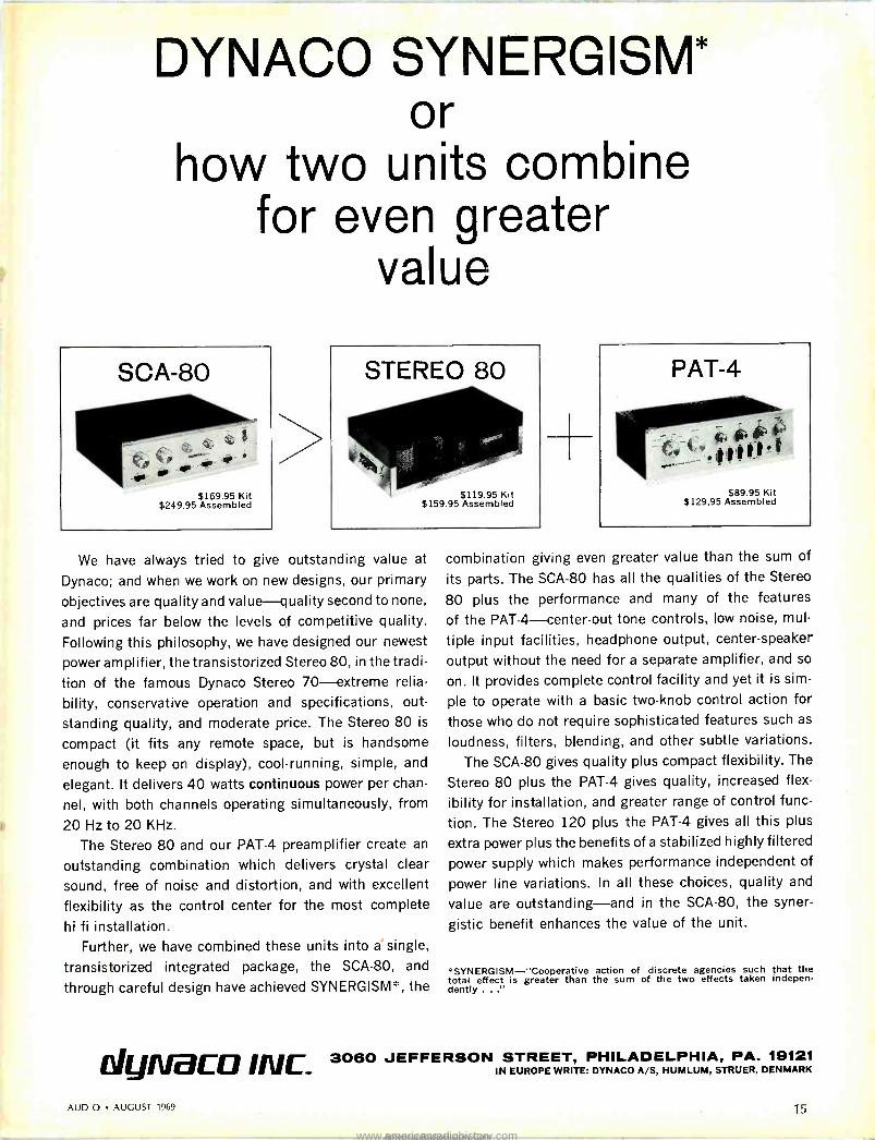
We have always tried to give outstanding value at
Dynaco; and when we work on new designs, our primary
objectives are quality and value-quality second to none,
and prices far below the levels of competitive quality.
Following this philosophy, we have designed our newest
power amplifier, the transistorized Stereo 80, in the tradi-
tion of the famous Dynaco Stereo 70-extreme relia-
bility, conservative operation and specifications, out-
standing quality, and moderate price. The Stereo 80 is
compact (it fits any remote space, but is handsome
enough to keep on display), cool -running, simple, and
elegant. It delivers 40 watts continuous power per chan-
nel, with both channels operating simultaneously, from
20 Hz to 20 KHz.
The Stereo 80 and our PAT -4 preamplifier create an
outstanding combination which delivers crystal clear
sound, free of noise and distortion, and with excellent
flexibility as the control center for the most complete
hi fi installation. Further, we have combined these units into a single,
transistorized integrated package, the SCA-80, and
through careful design have achieved SYNERGISM*, the
dynraco Inlc_
combination giving even greater value than the sum of
its parts. The SCA-80 has all the qualities of the Stereo
80 plus the performance and many of the features
of the PAT-4-center-out tone controls, low noise, mul
tiple input facilities, headphone output, center -speaker
output without the need for a separate amplifier, and so
on. It provides complete control facility and yet it is sim-
ple to operate with a basic two -knob control action for
those who do not require sophisticated features such as
loudness, filters, blending, and other subtle variations.
The SCA-80 gives quality plus compact flexibility. The
Stereo 80 plus the PAT -4 gives quality, increased flex-
ibility for installation, and greater range of control func-
tion. The Stereo 120 plus the PAT -4 gives all this plus
extra power plus the benefits of a stabilized highly filtered
power supply which makes performance independent of
power line variations. In all these choices, quality and
value are outstanding-and in the SCA-80, the syner-
gistic benefit enhances the value of the unit.
"SYNERGISM-"Cooperative action of discrete agencies such that the total effect is greater than the sum of the two effects taken indepen- dently ..."
3060 JEFFERSON STREET, PHILADELPHIA, PA. 19121 IN EUROPE WRITE: DYNACO A/S, HUMLUM, STRUER, DENMARK
AUDIO AUGUST 1969 15
www.americanradiohistory.comAmericanRadioHistory.Com

Tape Guide HERMAN BURSTEIN
If you have a problem or question on tape recording write to Mr. Herman Burstein at AUDIO, 134 North Thir- teenth Street, Philadelphia, Pa. 19107. Please enclose a stamped, self- addressed envelope. All letters are
answered.
Echo Effect
Q. I would like to make echoes on n .y * * * tape recorder. How do I do this?-Richard Firtik, Mountain View, Calif.
A. To achieve an echo effect with a tape recorder, it is necessary to be able to record and play simultaneously on a given track. The playback signal is fed back in attenuated form to the rec- ord head, so that it is re-recorded and played, etc., achieving something akin to an echo effect. The faster your tape speed, the more natural will be the effect. I do not know your particular tape recorder well enough do say whether it is equipped to produce echoes. Consult the instruction man- ual and/or manufacturer.
First Tape Recorder
Q. What nation put the first tape re- corder on the market? What advantage is there in a boom microphone?-Rich- ard Firtik, Mountain View, Calif.
A. So far as I know, Germany was the first to make really practical strides with the tape recorder, although other nations long before had achieved mag- netic recordings on wire. The U.S. started producing practical tape re- corders after World War II.
The advantage of a boom mike is in flexible placement of the microphone, including keeping it out of sight for motion picture, TV, or similar pur- poses. Also, use of a boom helps isolate the microphone from the floor, so that it is not affected by walking, stamping, and so on.
3.75-ips Equalization
Q. Could you please give me some information about tape recorder equali-
zation curves? I have gone through much literature and there just doesn't seem to be any standard for 3.75 ips. How can tapes recorded on one ma- chine play well on another if there is no standard equalization as in the case of phono recording? What recording equalization is the industry using for prerecorded tapes? What is the match- ing playback equalization?-L. Blom- berg, Montreal, Canada
A. In the United States, both NAB and RIAA within the past few years have standardized equalization for 3.75 ips as follows: With constant flux on the tape, the combined response of the playback amplifier and the tape head should be a bass -boost curve commenc- ing (3 dB up) at 1770 Hz and leveling off (3 dB below maximum boost) at 50 Hz. If the playback head is "ideal" (perfect), this bass -boost characteris- tic is the same as the playback equali- zation circuit. But practical heads are not ideal. To the extent they deviate from perfection-usually by exhibiting treble losses-such deviation must be made up in the playback amplifier. Therefore one frequently finds some treble boost in the playback equaliza- tion of a tape machine conforming to the NAB and RIAA standards.
There is no standard recording equalization. Instead, the NAB stan- dard requires recording equalization to be such that, in conjunction with the specified playback equalization and with "normal" bias, record -playback re- sponse will be relatively flat-essen- tially between 50 and 10,000 Hz at 3.75 ips.
Similar requirements apply to 7.5 ips. Now the combined playback bass - boost curve commences at 3180 Hz, and again levels off at 50 Hz. Record -play- back response is expected to be rela- tively flat between 50 and 15,000 Hz.
Tape -Head Contact During Fast Winding
Q. My tape machine does not contain tape lifters and therefore in running a tape on fast rewind or fast forward the tape is still in direct contact with the recording heads. Will this affect the re- corded portion of the tape and/or will this affect the heads of the recorder, such as excessive magnetizing? How often should I demagnetize the heads? My manual says "periodically" and this doesn't help me much. Can head demagnetization be done too much?- Allen T. King, Aberdeen Proving Ground, Md.
A. If your tape is indeed in contact with the heads during fast wind or
rewind, and if these heads are mag- netized, then the recording may be af- fected; there may be some high -fre- quency erasure, and the noise level may be raised. Further, and important, such contact tends to cause unnecessary wear of the heads. I suggest that in fast wind or rewind you try to find an alternate way of routing the tape so it doesn't contact the heads. Perhaps you can insert a smooth material, such as celluloid, between the tape and the heads during rapid motion. Very roughly, heads should be demagnetized after about every 8 hours of use. More frequent demagnetization will not hurt.
Comparison of SN's Q. I have two tape recorders and
would like to know which is the better. Machine 1 has a signal-to-noise ratio of about 50 dB at peak record level, while Machine 2 has a ratio of 54 dB. -Lou Bavaro, Jr., Schenectady, N. Y.
A. Assuming that both tape machines mean the same thing by "peak record level," then of course Machine 2 with 54 dB S/N is superior. However, if the meaning of peak record level differs, it is open to question which one is su- perior. Assume that for Machine 1
PRL corresponds to 1 per cent har- monic distortion at 400 Hz, while for Machine 2 PRL corresponds to 3 per cent distortion. Then Machine 1 is su- perior. A PRL at 1 per cent distortion is about 6 to 8 dB below a PRL at 3 per cent distortion. Therefore you are entitled to add about 6 to 8 dB to the S/N of Machine 1, which makes its S/N superior to that of Machine 2.
High Quality at Low Speed Q. Using low -noise tape and a cas-
sette tape recorder, I visualize full fre- quency response at 1.875 ips in a pocket size machine, capable of making re- cordings of professional quality. Is this feasible? How bad is the wow and flut- ter apt to be at 1.875 ips?-Bill Borne- misza, Saginaw, Mich.
A. In theory, frequency response relatively flat between 50 and 15,000 Hz can be achieved at 1.875 ips, using state-of-the-art techniques and compo- nents. I don't know that this can be achieved as yet in moderate price tape machines for home use. One problem, as you appear to recognize, is that of increased wow and flutter at reduced speed. Another problem is that in try- ing to stretch treble to 15,000 Hz or so it is probably necessary to sacrifice a fair amount in the way of higher dis- tortion and noise, so that performance is not up to professional standards. Æ
16
Check No. 17 on Reader Service Card -)
AUDIO AUGUST 1969
www.americanradiohistory.comAmericanRadioHistory.Com

The best stereo tape deck your money can buy. Period!
Better -than -Studio Specs. Frequency response: 20 Hz to 22 KHz, 40 Hz to 18 KHz ±2 dB@71/tips. S -N ratio at peak level to unweighted noise: (Model 770-2) 58 dB or better; (Model 770-4) 56 dB or bet- ter. Wow and flut- ter: less than 0.09% @ 71/2, less than 0.12% @
33/4, less than 0.2% @ 17/a.
Exclusive Sony Noise -Reduction System. Sony "SNR" automatically reduces gain of playback amplifier by 6 dB during very low passages, when background noise is most predominant. Noise level is greatly reduced, dynamic range ex- panded 100%. Also incorporated is a
built-in limiter to automatically con- trol overload distortion. Both "SNR" and limiter are switch defeatable.
Lightweight. A full 7 -inch reel capacity profes- sional studio tape deck. Pick it up and take it anywhere. Operates on a self -enclosed re- chargeable nickel -cadmium battery pack-or plugged into AC.
Three Speeds. 71, 33'/4, 17/e ips. Other features include two professionally - calibrated VU meters, built-in line -and -mike mixing, push-button operation, scrape flutter filter, low - impedance Cannon plug mike in- puts, tape/source monitoring.
Four Heads. The 770-2 has two -track erase, record, and playback heads plus a four - track playback head. The 770-4 has four -track erase, record, and playback heads plus a two -track playback head.
ServoControl Motor with VariSpeed Tuning. Auto- matically maintains exact speed during mechanical load changes and voltage variations. Built-in VariSpeed tuning permits vernier ad- justment of plus or minus 7% of any of the three speeds. Ideal for pitch tun- ing to any musical instrument.
Sony Model 770. Priced at $750. For a free copy of our latest tape recorder catalog, write to Mr. Phillips, Sony/ Superscope, Inc., 8142 Vineland Ave- nue, Sun Valley, California 91352.
SONY. SUP ; COPE ,.. F..-... n....
You never heard it so good.
+t969.SUPEFSCOPE,INC.
www.americanradiohistory.comAmericanRadioHistory.Com

EDITOR'S REVIEW
Good Show The Third Annual Consumer Electronics Show
(a dealer show), held in New York City in June, had 190 exhibitors showing their products. In addition, independent side shows were produced by some manufacturers in private suites at nearby hotels.
A great number of stereo hi-fi component manu- facturers participated in the show, side by side with package equipment manufacturers, provid- ing one with a virtual panorama of home enter- tainment equipment that will be featured in 1970. Among the exciting products we witnessed (some of which may not be marketed due to a variety of exigencies, past experience indicates) : an endless - loop cassette tape cartridge, a stereo FM scope monitor unit, a light -modulated phono cartridge, a $650 stereo FM receiver added to a moderately priced line, moderately priced electronics added to a premium -priced line, a compact system with a Staar cassette unit for continuous play, an 8 -track tape cartridge changer, 8 -track tape re- corder / reproducer, a Grandfather -clock -styled equipment cabinet with "stereo" speakers lined up vertically, cube -shaped speaker systems with all four enclosure sides available in a variety of colors, a tape speed timer, lightweight electrostatic
Advertising executive Jack Gilbert, 61, President of Gilbert & Felix, Inc., suffered a fatal heart attack this past June. His agency represented component equipment manufacturers dur- ing the formative years of the high-fidelity industry through to the present time. He was also a leader in the marketing of photo- graphic equipment, Nikon cameras being one of the brand names served by the agency.
Trained as an attorney, Jack Gilbert was an articulate spokesman for the hobbies he loved - audio and photography - probing deeply into each subject. He was a member of the Audio Engineering Society for many years, and a member of the Board of Direc- tors of Ehrenreich Photo -Optical Industries, Inc. since 1964. In addition, he was a Past Master of his Masonic Lodge.
His storehouse of knowledge and great wit will be missed by all who knew him.
headphones, new, good -quality amplifier and re- ceiver kits, a $159.95 automatic turntable, auto cassette systems, speakers that are nearly paper thin, and speakers taller than a man stands.
* * *
The East Coast buying public may not be able to enjoy a New York City IHF-sponsored hi-fi show for the first time since the annual show started in the 50s. It was originally planned to follow the Los Angeles Hi-Fi Music Show (Sep- tember 28 -October 5, Hollywood Roosevelt Hotel) by about one month with a New York Coliseum - located show. But amidst strong objections from many IHF members to the Coliseum as an ap- propriate setting and to holding annual shows in New York's borough of Manhattan, it was voted down by the IHF Board of Directors. Alternate proposals have been made, none of which has been accepted at this writing.
Innovations Report Altec Lansing introduced a radicallÿ different -
looking VU meter recently. The new volume level indicator is a peak -reading device that contains a vertical array of seven lights. It is calibrated in modulation percentages, 6%, 16%, 25%, 40%, 63%, 100%, and overload, using blue, four green lights in succession, yellow and red. According to a company spokesman, "... the new display answers multi -track monitoring problems." He noted that "... it is very simple for the eye to follow a multiple array of colored lights as op- posed to watching many meter needles."
Plans for production of CBS' Electronic Video Recording (EVR) cartridges are moving ahead. A production facility has been leased in New Jersey, as the company enters the "final plan- ning phase for marketing the EVR system." A European EVR cartridge plant is also said to be in the process of being equipped. If successful, EVR may well challenge the "Super 8" home motion picture format, not to mention home video tape recorders, if the cost of the cartridge is com- petitively priced. And that's a big "if," especially since mum's been the word on costs.
Free Product Information AUDIO Magazine readers can obtain free prod-
uct information directly from manufacturers who advertise in its pages or who are mentioned edi- torially whenever a "Check No. xx on Reader Service Card" appears. Simply complete the post- paid Reader Service Card that appears opposite the last page in each issue, checking off the ap- propriate reader service number. We do the rest. With the aid of a computer, your requests for information are rushed to manufacturers for their reply. Most manufacturers respond promptly. A rare few, however, do not respond with dispatch, readers have advised. For the latter, we apologize.
A.P.S.
18 AUDIO AUGUST 1969
www.americanradiohistory.comAmericanRadioHistory.Com

WØODWIND P
Agri
_._........f - .. .. .. Words are inherently limited in stimulating
the emotions aroused by music. This is especially so in describing how high fidelity components perform.
With cartridges, for example, we speak of flat frequency response, high compliance, low mass, stereo separation. Words like these enlighten the technically minded. But they do little or nothing for those who seek only the sheer pleasure of listening.
We kept both aspects in mind when developing the XV -15 series of cartridges. We made the technical measurements. And we listened.
We listened especially for the ability of these cartridges to reproduce the entire range
of every instrument. With no loss of power. In the case of woodwinds, this meant a cartridge that could recreate the exact nuances that distinguish an oboe from an English horn. A clarinet from a bass clarinet. A bassoon in its lower register from a contrabassoon in its higher register.
We call this achievement "100% woodwind power." When you play your records with an XV -15, you won't be
concerned with even that simple phrase. Instead, you'll just feel and enjoy the renewed experience
of what high fidelity is really all about. PICKERING
Check No. 19 on Reader Service Card
THE NEW PICKERING XV15/750E. PREMIER MODEL OF THE XV -15 SERIES.TRACKS AT % TO 1 GRAM. DYNAMIC COUPLING FACTOR OF 750 FOR
USE IN FINEST TONEARMS. $60.00. OTHER XV15 CARTRIDGES FROM $29.95. PICKERING & CO.,PLAINVIEW, L. I., N.Y.
www.americanradiohistory.comAmericanRadioHistory.Com

Layman'
MIC SPEC ii IC
JAMES LONG*
The Nominal Curve
The most important indication of a microphone's subjective performance is its "frequency response," the way it "hears" sound. Frequency characteris- tics, despite their importance are fre- quently and casually stated, for in- stance, as "30 to 20,000 Hz" without reference to limits (like ±3 dB) or to the response characteristics within these limits.
The first step toward clarifying mat- ters is the specification of a nominal frequency response as shown in Fig. 1.
The response certainly extends from 30 to 20,000 Hz, but the design engineer apparently had in mind something other than absolutely flat response be- tween the two frequency extremes!
Now we know something. But Fig. 1
does not rectify the lack of a deviation - from -nominal specification. In reality, it would be nearly impossible for any one production -line microphone to meet the exact nominal frequency re- sponse characteristic shown in Fig. 1.
NE ONS
An extremely high -quality professional microphone might be specified as de- viating no more than ±1.5 dB from the nominal response over much of its range, as in Fig. 2. Microphones of lesser quality have much broader tol- erances, especially at the frequency extremes. Figures 3 and 4 illustrate tolerances for two microphones, along with the response of a typical produc- tion -line unit. Though such tolerances are usually not published except for some professional microphones, most manufacturers employ similar limits for evaluating production output.
Figure 3 represents a more modest unit. The broader tolerances of Fig. 3
invite more variation from microphone to microphone as well as degradation of overall sound quality, but the response variation within the still fairly "tight" response limits of Fig. 3 is suitable for many demanding applications.
Extremely wide response variations around the nominal curve, either in the form of broad shape or in the form of
Fig. 1 - (upper). Nominal frequency response. Fig. 2 - (lower). Response limits for high -quality microphones.
00
Fig. 1
Fig. 2
rapid up-and-down variations, more or less negate the whole concept of nomi- nal curve. Such microphones, even though they carry the same model numbers, would effectively be separate entities unto themselves, with profes- sionally unacceptable mic-to-mic varia- tion and general performance. Figure 4 shows the response limits of an inex- pensive dynamic microphone, along with two widely different response curves, both of which fall within the envelope. The different response curves are not likly to occur during the same production run, but probably represent run -to -run variation due, for instance, to small changes in the position or amount of adhesives, or to misadjust- ment of a small piece of felt. Such changes of process would not be toler- ated in the production of the more ex- acting microphones of Figs. 2 and 3. Their more stringent response limits would stop the line at once, until the process change was identified and cor- rected.
The range and shape of response must be selected to meet the require- ments of a specific application. Except for special -effects recording, the serious amateur will probably require a micro- phone that covers, in some sense, the frequency range from 50 Hz to 13 kHz or somewhat beyond. But how flat? Most everyone wants amplifiers, tape recorders, and loudspeakers to exhibit the flattest response possible, but mi- crophones are often, and very effec- tively, tailored to control acoustic conditions and to provide the desired "sound." After all, it is the sound of the recording that is important, not whether or not it was made with a ruler -flat microphone. The closely spaced peaks and troughs of Fig. 4 are almost sure to make trouble. Smooth but shaped nominal curves, however, are very helpful in controlling acoustic conditions and supplementing the equalization available in professional consoles. For the serious amateur, of
Fig. 3 -(upper). Response limits for moderately high -quality microphones. Fig. 4- (lower). Response limits, inexpensive dy- namic microphone.
- -----
i' i,f\`
Response of Typical Microphone 11
1 t //// /
100 1000
FREQUENCY IN HERTZ
10k 20k
--------------
Fig. 3
TYPICAL RESPONSE A
'` '` ,rlv 1/4....
__- ------------- - . N /1
F94 I CAL RESPONSE T
100 1000
FREQUENCY IN HERTZ
1,. 1
%
20k
Electro -Voice, Inc.. Buchanan, Mich.
20 AUDIO AUGUST 1969
www.americanradiohistory.comAmericanRadioHistory.Com

100 1000 10k 20k
FREQUENCY IN HERTZ
Fig. 5-"Tailored" response curve.
Fig. 6
r1í4 in.
Fig. 6-(left). "Proximity effect" response variation with distance.
Fig. 7-(right). Directional characteristics of a 2" diameter omni-
directional microphone-frequency response at various angles.> 20 100
FREQUENCY IN
course, such "pre -equalized" micro- phones are the only help.
For instance, imagine a hypothetical recording of a pipe organ in a reverber- ant church. There is no doubt that a wide and smooth frequency range is desired, but flat response may not pro- vide the "best" results. This occurs be- cause microphones - even in stereo - are grossly inferior to human ears in discriminating between direct and re- verberant sound. The reverberant sound is characteristically bass -heavy, since higher frequencies are more rap- idly absorbed than the lower ones. Thus, a ruler -flat microphone, espe- cially directional types, can sound "muddy" when placed far enough back in the hall to get reasonable perspec- tive. The recording can lack the in- cisiveness of the in -person sound. For the reverberant church, then, a tail- ored, smooth roll off below 200 Hz (perhaps 5 to 6 dB down at 50 Hz), coupled with a subtle rise in the 6- to 12 -kHz range, may provide a subjec- tively more "flat" organ sound than that of Fig. 2-a ruler -flat microphone with response ±2.0 dB from 48 to 17,000 Hz. The professional audio man, with a console full of equalization fa- cilities, might best obtain the same re- sults by starting with the flat micro- phone. The amateur recordist, how- ever, dealing with fairly reverberant environments (churches, auditoriums, etc.) in covering fairly large groups (choirs, bands, etc.) with one or two microphones may very well benefit by having at his disposal a microphone with a frequency characteristic as shown in Fig. 5.
This is not to suggest that a micro- phone with the flattest response possi- ble is not desirable. Some situations will demand such a microphone. The intent is to point out that subjectively superior results can be obtained by us- ing just enough range to do the job and/or the correct response tailoring to take best advantage of acoustic con- ditions.
Fig. 7
Response vs. Distance
With all the pitfalls in specifying and choosing frequency -response character- istics, we might hope that these char- acteristics would be the same regardless of the distance from sound source to microphone. However, some micro- phone types are very much affected by variations in working distance!
Microphones whose output results from sound pressure impinging on only the front of the diaphragm, mostly om- nidirectional types, have a response that is constant with respect to work- ing distance. Directional microphones, however, including so-called "unidi- rectional," "cardioid," and "bidirec- tional" types with condenser, dynamic, ribbon, or ceramic generating elements, possess "proximity effects," the boost- ing of bass frequencies when the micro- phone is used close-up. The output of these microphones is proportional to the difference in pressure at the front and rear of the diaphragm, and this pressure difference becomes very large at low frequencies when the micro- phone is close to the source. Ribbon microphones and so-called "single -D" dynamic and condenser cardioids are especially prone to proximity effect. Single -D microphones are identified by a single entrance to the rear of the diaphragm, located near the front of the microphone case. The proximity effect of a typical single -D cardioid is shown in Fig. 6. The bump of re- sponse at one -quarter inch, relative to the 24 -inch response, is 14 dB at 100 Hz. (Generally, beyond 24 inches or so, response of single -D microphones remains constant.) Although this effect is not of great importance for working distances of two feet or more, the widely -varying low -frequency at closer working distances can be a problem or an effective low -frequency -boost equali- zation tool, depending on the user's requirements.
The proximity effect described above can be reduced through the so-called "variable -D" design. This approach provides more than one entrance to the
1000
HERTZ
10k 20k
rear of the diaphragm. Low frequencies are forced to enter somewhere near the rear of the microphone case so that even when a vocalist practically touches the front of the microphone, he is not close enough to the rear of the microphone to develop substantial proximity effect. The minimized prox- imity effect of a variable -D cardioid microphone is shown in Fig. 6.
DIRECTIONAL CHARACTERISTICS
A microphone's directional charac- teristics describe its response to sounds arriving off axis, in addition to the front, or on -axis frequency -response curves discussed above. Microphone performance potential is often judged by only this previously discussed curve. Since we are always pointing micro- phones at things, it would seem logical that the front response would be wholly satisfactory. It is a good general indica- tion, but makes complete sense only if the microphone is in an absolutely echoless environment (like the engi- neer's anechoic chamber) and is pointed directly at a single sound source. In the real world, however, room sound, or reverberation, enters the microphone mostly off axis. Furthermore, many in- struments or groups are located off axis. Thus, any perturbations in a mi- crophone's directional characteristics can introduce unwanted equalization and a generally unacceptable sound.
A microphone's directional charac- teristics are typically specified in two ways. First, they will be represented by a family of frequency -response curves at various angles around the microphone. This approach covers all the frequencies, but misses a lot of angles! Second, the directional charac- teristics may be represented by a fam- ily of "polar curves," taken at various frequencies. This method covers all the angles, but misses lots of frequencies. The details of both methods will be dis- cussed as basic microphone directional characteristics are presented below. In general, microphones of all generating -
AUDIO AUGUST 1969 21
www.americanradiohistory.comAmericanRadioHistory.Com

180
Fig. 8-Polar diagram of the microphone described in Fig. 7.
source types - condenser, ribbon, dy- namic, ceramic, etc.-may be designed around any of these characteristics.
The Omnidirectional Microphone.
The least complex directional char- acteristic is possessed by the so-called omnidirectional microphone. From its name, this microphone would be ex- pected to respond equally to sound from all directions at all frequencies. Upon closer inspection, however, this is found definitely not to be the case. The on -axis frequency -response curves discussed earlier give only a partial pic- ture of an omnidirectional microphone's performance with respect to frequency.
The problem arises because any phy- sically realizable microphone has finite size. The long wavelengths of low fre- quencies are not affected by this size. They will go around almost anything and exert pressure on the microphone diaphragm. But higher frequencies, with their short wavelengths, are quite disturbed by the microphone in their way: they reflect and diffract from and around the case, so that their pressure is never able to register fully on the microphone diaphragm. Maintaining a constant distant from the source, the higher -frequency output of the mike is attenuated more and more as the source is moved off -axis. The effect is more pronounced as microphone size increases. Figure 7 shows a family of frequency -response curves for an omni- directional microphone of 2 inches di-
ameter, at various angles. Figure 8 shows the same effect for the same mi- crophone from a polar curve stand- point. With a given frequency input, the microphone faces the source at 0 deg. Maximum output is obtained at this angle, and is labeled, for conve- nience, "0 dB" at the outer circum- ference of the polar plot. The 500 -Hz output, least affected by microphone size, traces out an almost perfect cir- cle as the angle off microphone axis is varied, The higher frequencies, suffer- ing attenuation off -axis, depart from the maximum -output 0 -dB circle soon after the microphone begins to turn. At 10,000 Hz, for instance, the microphone output shows a reduction of 16.5 dB at 90 deg.
Figure 9 presents similar informa- tion for an omnidirectional microphone of smaller diameter (17/32 inches). This unit is only 11.5 dB down at 10,000 Hz, 90 deg. off axis.
Either of these two "omnidirection- al" microphones will dull the sound of off -axis pickup. Depending on the user's requirements, this may be a problem or a good portable roll -off fil- ter! For instance, on the good side, the recordist forced to place a solo micro- phone too close for natural perspective, may take the "edge" off the vocal pick- up by having the soloist perform at 90 deg. off microphone axis.
The Cardioid Microphone
The term "cardioid" refers to a heart -shaped polar pattern. Cardioid microphone response is typically down about 6 dB at 90 deg. off axis, and about 15 dB at 180 deg. off axis. While a di- rectional characteristic of an omnidi- rectional microphone is moderate, and then only at higher frequencies, the cardioid directional characteristic is pronounced. In general, compared to an omnidirectional microphone, a car- dioid, will allow a significantly greater working distance for the same amount of "room sound" in the microphone pickup. Also, by judicious angling and placement in multiple mike recording setups, significantly better isolation be- tween channels and more controllable
Fig. 9-(below). Directional characteristics of a 17/32" diameter om- nidirectional microphone-frequency response at various angles.
Fig. 10-Directional characteristics of an "ideal" cardioid micro- phone-frequency response at various angles.
46 Deg.
/a Deg.
11 1/2 OR
at 90 Deg.
10.00052
20 100 1000 10k 20k
FREQUENCY IN HERTZ
balance between instrumental group- ings may be obtained than with omni- directional units. Finally, a cardioid directional characteristic will increase the likelihood of high gain -before -feed- back in sound -reinforcement applica- tions.
Unfortunately, the statement that a microphone is "cardioid" often fails to describe the true performance of the microphone. Ideally, all directional mi- crophones should exhibit no discrimi- nation with respect to frequency, but only an over-all reduction in level as the sound source moves off axis. These ideal characteristics are displayed on Figs. 10 and 11. Figure 10 shows re- sponse curves that are identical with respect to frequency, though of course lower in level as the source moves off - axis. Figure 11 gives the polar plot rep- resentation of the samè microphone's directional characteristics. One pattern will do for all frequencies in this ideal microphone. There are a few direc- tional microphones that approach this ideal. Most are far from it. Though their polar patterns may be adequate in the mid -frequencies, they are fre- quently far from uniform at low and high frequencies. The result is a color- ation of sounds arriving from off axis -including room reverberation and the sound of off -axis instruments-far more severe than that inherent in omnidirectional microphones. A typi- cal cardioid-microphone-with-a-prob- lem is shown in Fig. 12. Suppose a recordist were attempting to obtain proper balance, say, between a choir and orchestra by correct angular orien- tation of this cardioid microphone. The level of sounds arriving off axis, from the group he was trying to suppress, would be down in level in an average sense, but hopelessly colored and far from high-fidelity. A look at the direc- tional characteristics of the micro- phone, of course, give a quick indica- tion of the coloration to be expected. Watch out!
Though the cardioid and omnidirec- tional polar patterns are most widely used, several more -specialized charac- teristics are of note. The bidirectional, or figure -eight, pattern suppresses
0 Deg.
9"v Deg.
100 1000
FREQUENCY IN HERTZ
10k 20k
22 AUDIO AUGUST 1969
www.americanradiohistory.comAmericanRadioHistory.Com

o
Figs. 11, 12, 13, 14-Polar responses for an "ideal" cardioid (Fig. 11), a cardioid-with- a-problem (Fig. 12), an "ideal" bidirec- tional (Fig. 13), and an "ideal" super- cardioid (Fig. 14) with a standard cardioid
shown in dotted lines for comparison.
sound from the sides while being sensi- tive at the front and rear. The bidirec- tional's characteristic 90 -deg. nulls are shown in Fig. 13. Various stages be- tween cardioid and bidirectional are possible, with two minimums occurring at varying degrees off axis. One stage, the "super-cardioid" with nulls 150 deg. off axis, is frequently useful. It provides somewhat greater reduction at the sides and just to the rear of the sides than can be attained with the standard car- dioid pattern, with only a relatively small reduction in rear cancellation. Figure 14 shows the super-cardioid along with the standard cardioid (dotted line) for comparison.
Another unique, specialized direc- tional characteristic is possessed by the so-called "shot gun" microphone. Such units are typically based on a long in- terference tube which permits ex- tremely high rejection 90 deg. off axis, far in excess of the 6 dB associated with cardioid design. The polar pattern of such a microphone is shown in Fig. 15. Unfortunately, the beam width of an interference -tube microphone is very much a function of frequency, even in the best designs, and it is nearly im- possible to obtain a truly uniform pat- tern. Instead, the pattern becomes narrower and narrower with increasing frequency. If the on -axis response is flat, the sound of this shot -gun micro- phone in a reverberant room will be definitely on the tubby side, since very little high -frequency information is be- ing gathered.
MICROPHONE IMPEDANCE AND LOADING
Microphone impedance refers to the impedance seen when electrically "looking back" into the unit's output terminals. Microphones are roughly de-
scribed as either high or low imped- ance. Low impedance typically refers to 50 to 250 ohms, while high imped- ance refers to 25,000 ohms and on up to several megohms. Low -impedance microphones are casually thought of as useful where long lines must be run without degradation of high -frequency response. Conversely, high -impedance microphones are thought of as approp- riate for much shorter cable runs though possessing an open -circuit out- put voltage about ten times that of low - impedance types.
Resistive -Source Microphones
Dynamic, ribbon, and condenser mi- crophones (after the output of the fol- lower stage) may be generally charac- terized as resistive -source transducers. These microphones may be modeled as an electrical generator, Eo, in series with the internal impedance of the microphone, Ro. When such a micro- phone is connected to a preamp through a cable, the microphone is in effect seeing an additional series re- sistance (for all practical purposes, the input resistance of the preamp) and a shunt capacitance (primarily due to the microphone cable) , whose imped- ance magnitude varies according to the formula
Zcc I (ohms) = 27rf Cr'
where f = frequency in hertz and Cc = capacitance in farads. The situation is shown in Fig. 16.
For resistive -source transducers, ca- ble capacitance tends to roll off high - frequency response. This occurs as follows: at low frequencies, Co is essen- tially an open circuit, and may be ig- nored. The source voltage, E0, appears across Ro in series with RL, and as is commonly the case, if RL is 10 or 20 times as large as R0, most of E0 ap- pears across RL, alone, right where we want it. As frequency is increased, how- ever, Cc starts to look more and more like a short circuit rather than an open circuit. When Cc has an impedance value equal to R0, Eo will be divided evenly across Ro and Cc, with the re- sult that microphone response is now down 6 dB at that frequency. For high - impedance microphones, with high R0, this occurs at a relatively low fre- quency and for relatively short cables (i.e., relatively low cable capacitance). For low -impedance microphones, this occurs at a relatively high frequency, far outside the audible range, and for extremely long cable, on the order of several hundred feet. For instance, a mere 10 feet of cable on a 30,000 -ohm high -impedance microphone puts the response down 3 dB at 7800 Hz, per- haps unacceptable. In contrast, a microphone with Ro = 200 ohms is down 3 dB with 500 feet of cable at about 23 kHz, probably acceptable.
1
270
Dao
SAo 145 'h"
22s
000 A-10, Hz B- 2,500Hz 180
1356
90°
C-1,000 Hz D- 100Hz
Fig. 15-Polar response curve of shot- gun microphone at various
frequencies.
Mic Cable Load
Eo
Fig. 16- Equivalent source microphones.
Resistive loading of resistive -source microphones has no effect on frequency response over a broad range of varia- tions. Over-all output voltage, however, is affected. The microphone will pro- duce its highest output voltage when the load resistance, RL, is effectively an open circuit (i.e., at least 20 times the nominal internal impedance) . If the load is reduced to the same impedance as the microphone, as is often the case, microphone output will be reduced by 6 dB. Further reductions in load will further reduce output. This effect is shown in Fig. 17 for various values of Ro/RL. Thus, in accordance with the preceding discussion on resistive load- ing effects, output at low frequencies suffers. A nominal 150 -ohm cardioid microphone with a rising low -end im- pedance, would sound thin if loaded with significantly less than 150 ohms. Omnidirectional microphones have constant impedance characteristics, and are not affected by extremely small loads from a frequency -response stand- point.
circuit for resistive -
Capacitive Source Microphones
Ceramic and crystal microphones may be classified as capacitive -source transducers. Such microphones are re- ferred to as high impedance, but this impedance is purely capacitive and of quite a different nature than the re- sistive high impedance, say, of a dy- namic microphone. The impedance magnitude is a function of frequency:
I Zco I (ohms) = 1
27rf Cc
(Continued on page 61)
AUDIO AUGUST 1969 23
www.americanradiohistory.comAmericanRadioHistory.Com

" Sansui? Oh, yes, they make the greatest
stereo receivers in the world"... ..
&
Sansu 350 46 walls 3199.95
Sansui 800 70 waits :249.95
Sansui 2000 100 w.z Its $299 95
igait
tar _
Sansui 5000 180 wets.. $449.95
S s SANSUI ELECTRONICS CORP. 14:x dsidE, New York, 11377 Los Angeles, Zalifornia, 90007
SANSUIELECTRICCO..LTD..Torvo.JapanELrrreanOfficeFranklirta.M,WestGsrmanyBectronisDistribitors Canada), British Zolumtia
24 AUDIO AUGUST 1969
www.americanradiohistory.comAmericanRadioHistory.Com

The new Sansui SP1001 3 -way 3 -speaker system incorporating a new concept in speaker design 35 to 20,000 Hz Frequency Response
Special level controls to change output levels of the midrange & tweeter independently Built-in ellectronic crossover system terminals for the Audiophile "dream system' Push button connection terminals
Beautifully finished walnut with hand -carved fretwork grille ....$139.95
"and stereo control amplifiers, new power amplifiers, and multi -channel dividers"
AUDIO AUGUST 1969 Check No. 25 or Reader Service Card 25
www.americanradiohistory.comAmericanRadioHistory.Com

A Lek At
PUBLIC ADDRESS AMPLIFIERS LEO G. SANDS
American Geloso battery - powered amplifier.
Bogen MTA60 mixer -amplifier.
CM Labs 702 power amplifier.
University Sound "Power -Line" mixer -amplifier.
AMPtsFIExs for public address pur- poses differ markedly from stereo hi-fi home entertain-
ment equipment. For example, they are usually built for continuous duty at their upper power level, have facilities for controlling the level of multiple sources independently and through a master control, include output stages for driving many speakers located long distances from the amplifier, and often have high- and low -impedance inputs for microphones.
In direct contrast to home hi-fi sys- tems, they are generally monophonic types rather than stereophonic units, exhibit much higher levels of distor- tion, have narrower frequency -response and tone -control ranges, and do not in- clude such niceties as rumble filters. Whereas consumer component equip- ment numbers stereo FM receivers as a major seller nowadays, it is rare when PA equipment strays from the power amp/mixer-preamp unit. The PA units range from cheap -and -dirty $50 types to higher -power, more -versatile $185 or so amplifiers. Much beyond this price area, one meets with commercial sound power amplifiers that are used for pro- fessional audio purposes such as broad- cast and studio work, as well as for
top-quality sound reinforcement appli- cations. These are separate power am- plifier and audio control centers, with the latter often being customized con- trol consoles; they are not designed for use as paging amplifiers.
The earliest PA systems employed a carbon microphone and a speaker-no amplifier. According to available his- torical data, the first amplified PA sys- tem was used by President Woodrow Wilson in San Francisco in 1915. It was also in the San Francisco area that Peter Jensen developed an electro- dynamic speaker and where Magnavox started producing horn speakers with a driver employing a voice coil attached to a diaphragm.
By 1929, several companies, includ- ing Sangamo and Silver -Marshall, were producing PA amplifiers. Output power was quite low, seldom more than 5
watts, since the best available output tubes at the time were triodes such as the type 10 and VT -2. Then came along the type 50, which in turn was obso- leted by the 2A3. Both were triodes and capable of handling more power. Where greater power was required, some amplifiers used 50 -watt trans- mitter tubes. The development of the 6L6 beam power tube paved the way
for higher -output amplifiers at lower cost.
While most PA amplifiers are used at locations where 115 -volt a.c. power is available, many are used on con- veyances where only low voltage d.c. is available. Until transistors became available, this made it necessary to de- sign amplifiers powered from a dyna- motor or vibrator power supply. The development of the transistor in 1947 and the subsequent advances in solid- state technology opened up a whole new era in PA amplifier design. It be- came possible to design mobile ampli- fiers which could be operated directly from a 12 -volt d.c. source and which did not require a built-in power supply. However, in the case of a.c.-operated, solid-state amplifiers, it is still neces- sary to include an a.c.-to-d.c. power supply. And in some mobile amplifiers in which higher d.c. voltages are re- quired in order to get adequate audio power output, a d.c.-to-d.c. step-up power supply is required.
The end -result sound quality of PA systems has been improved during the past 30 years, but not as significantly in sound quality as one would imagine.
But there has been progress. Solid- state amplifiers are plentiful. Their
26 AUDIO AUGUST 1969
www.americanradiohistory.comAmericanRadioHistory.Com

electric power efficiency is much higher than that of tube -type amplifiers. They run much cooler and, because high d.c. voltages are not required, component failures are likely to be less frequent. With long -life transistors, maintenance costs are lower now. Too, today's breed of PA amplifiers are smaller and more flexible.
Using modern transistor circuits, it is possible to eliminate the output trans- former in an amplifier, thereby lower- ing cost and a source of distortion. Without transformers, output power capability is reduced as speaker load impedance is increased, of course. Fur- thermore, transistors can be damaged if the speaker leads open or are shorted to the chassis unless protective circuits or devices are used.
Constant Voltage System
In sound system applications, it is oftentimes preferable to feed speakers through a relatively high voltage line (25 volts or more) in order to minimize power losses in the feed lines. There- fore, an output transformer is often used in PA amplifiers. If there is no
TABLE 1
Speaker Voltage/Watts Table
VOLTS*
Watts Consumed by Speaker
4 -ohm 8 -ohm 16 -ohm
1 0.25 0.125 0.063
2 1 0.5 0.25
3 2.25 1.12 0.56
4 4 2 1
5 6.25 3.12 1.56
6 9 4.5 2.25
7 12.25 6.12 3.06
8 16 8 4
9 20 10 5
10 25 12.5 6.25
11 30 15 7.5
12 36 18 9
13 21 10.5
14 24 12
15 28 14
16 32 16
17 18
18 20
19 22
20 25
21 27
22 30
*across speaker voice coil
output transformer in the amplifier, an external transformer may be used to step up both voltage and impedance. At least one manufacturer-University Sound-has moved away from the con- stant voltage system (which requires an output transformer) , leaving it as an option should one have a valid reason for using it.
PA amplifiers are usually provided with a variety of output terminals to provide installation versatility. Some may have only a 16 -ohm output, but most have 4-, 8- and 16 -ohm outputs and some have 2-, 8-, 16- and 32 -ohm outputs. Some early amplifiers also had a 500 -ohm output. More recent ampli- fiers have a 25 -volt or 70 -volt output, or both, or provision to plug in appro- priate transformers, in addition to low - impedance outputs. Some also have 115 -volt output terminals.
When the low -impedance outputs are used, it is intended that the speakers be connected to the amplifier through relatively short cables. Figure 1 shows some examples of direct speaker con- nections.
To drive speakers at considerable dis- tances from the amplifier requires long cables, of course. It is customary in these instances to employ step-down transformers at each speaker or speaker -cluster, and to feed the speaker line(s) from the 500 -ohm, 25- or 70 -volt (or 115 -volt) output terminals. The system used for feeding speakers in such a way is commonly called a "con- stant voltage sound system." Just be- cause an amplifier has output terminals labeled "70 volts" does not necessarily mean that it is a true constant -voltage amplifier. The output signal level will not be sustained at 70 volts unless the amplifier contains an automatic gain circuit (AGe) to offset variations in input signal voltage, or unless the input signal itself is at a constant level. In a constant -voltage sound system the am- plifier should have excellent output voltage regulation even if it doesn't have AGe. If output voltage regulation
is poor, the main benefit is lost. The output level of the speakers will vary when one or more speakers is discon- nected or its loading is changed.
Ampli fier Output
Fig. 1-Hookup speakers using
of four 16 -ohm loud - the impedance -matching method.
In the case of a 10 -watt amplifier, the 70 -volt output is the same as a 500 - ohm output. At 10 watts output level, the voltage across the 500 -ohm ter- minals will be 70.7 volts since 70.7 is equal to the square root of watts times impedance (5000). Therefore, 10 watts of audio can be fed into a 70 -volt speaker feed line from the 500 -ohm output terminals.
And, in the case of a 75 -watt ampli- fier, the 25 -volt output can be the same as the 8 -ohm output. Table 1 lists the approximate voltages at various output terminals specified in terms of output impedance. Figure 2 shows examples of amplifier output connections.
In a conventional impedance -match- ing type of sound system, the combined input impedance of the speakers is matched to the output impedance of the amplifier, as previously illustrated in Fig. 1. When the amplifier feeds a 500 -ohm line, transformers are used at each speaker. For example, when there are four speakers, the transformer taps are set so that each speaker has a re- flected impedance of 2000 ohms. Thus, four 2000 -ohm loads can be paralleled across the 500 -ohm output terminals of the amplifier, as shown in Fig. 3.
TABLE 2
Output Voltage vs. Impedance
Watts ohms for 25 volts
ohms for 70 volts
volts at
4 ohms volts at
8 ohms volts at
16 ohms volts at
500 ohms
10 63 500 6.3 9 13 70
30 20 166 11 15 22 120
50 12 100 14 20 28 160
70 9 70 17 24 34 190
100 6.3 50 20 28 40 220
AUDIO AUGUST 1969 27 www.americanradiohistory.comAmericanRadioHistory.Com
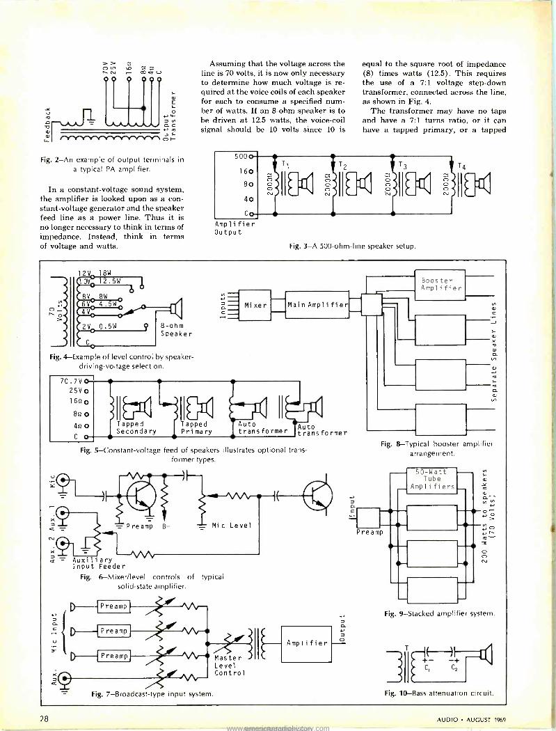
ji;
i v E L
7 O y 7 V1
CL C N i O
Fig. 2 -An example of output terminals in
a typical PA amplifier.
In a constant -voltage sound system, the amplifier is looked upon as a con- stant -voltage generator and the speaker feed line as a power line. Thus it is no longer necessary to think in terms of impedance. Instead, think in terms of voltage and watts.
Assuming that the voltage across the line is 70 volts, it is now only necessary to determine how much voltage is re- quired at the voice coils of each speaker for each to consume a specified num- ber of watts. If an 8 -ohm speaker is to be driven at 12.5 watts, the voice -coil signal should be 10 volts since 10 is
5000
160
80
40
Co
Amplifier Output
equal to the square root of impedance (8) times watts (12.5). This requires the use of a 7:1 voltage step-down transformer, connected across the line, as shown in Fig. 4.
The transformer may have no taps and have a 7:1 turns ratio, or it can have a tapped primary, or a tapped
O CsJ KDEC MCI(
ö ó ME< b(
Fig. 3-A 500 -ohm -line speaker setup.
12V 18W
10V
8V 8W
6V 4.5w 4V
8 -ohm Speaker
Fig. 4 -Example of level control by speaker- driv ng-voltage selection.
70.7VO 25V
162 8u 0
42 0 C 0
U
X
¢
Mi xe r Main Ampli fier
171 Tapped Secondary
Tapped Primary
Auto transformer Auto
transformer
Fig. 5 -Constant -voltage feed of speakers illustrates optional trans- former types.
Preamp B- Mic Level
Auxiliary VOV Input Feeder
Fig. 6-Mixer/level controls of typical solid-state amplifier.
P re amp
P re amp
P re amp Master Level Contro I
Boos ter Amplifier
Fig. 8 -Typical booster amplifier arrangement.
50 -Watt Tube
Amplifiers
Pre amp
Fig. 9 -Stacked amplifier system.
C
= Fig. 7 -Broadcast -type input system. Fig. 10 -Bass attenuation circuit.
28 AUDIO AUGUST 1969
www.americanradiohistory.comAmericanRadioHistory.Com

Incomparable...
Heathkit AR -15 AM -FM Stereo Receiver Dozens of new stereo receivers debut every year and all claim simul- taneous occupation of that singular pinnacle - perfection. Ad- mittedly, some of the very expensive receivers are good ... at the time of their introduction. Few manufacturers would have the con- fidence to suggest that the same product still retains its grasp on perfection two years later.
We do.
Heath introduced the AR -15 almost two years ago, and we still advertise it as "Incomparable" ... for the simple reason that it still is. It is so undeniably advanced that others have just recently begun to adopt some of the features Heath innovated two years ago .. .
the crystal filter/integrated circuit combinations that deliver ideal selectivity and never require alignment ... the massive 150 watt amplifier with its superb frequency response and ultra -low IM and harmonic distortion ... the use of two accurate tuning meters for exact station selection ... the readily accessible, but hidden secon- dary controls ... the elaborate noise -operated squelch circuit that quiets between -station noise before you hear it. Many have tried, but no one has succeeded in designing a receiver with all the per- formance, features and value of the Heathkit AR -15.
In the next column are some of the specifications that have made the Heathkit AR -I5 the world's fastest selling, most highly praised AM -FM Stereo Receiver in the history of the industry. Every leading audio critic, every major electronics editor, leading consumer testing labs and thousands of owners agree that the AR -15 represents the ultimate available today in a solid-state receiver. Compare these specifications with those of other receivers - compare the prices - compare the critical analyses made by the experts. You'll find that the Heathkit AR -15 is, in a word, incomparable.
Kit AR -15, (less cabinet), 34 lbs $339.95* Assembled ARW-15, (less cabinet), 34 lbs $525.00* Assembled AE -16, optional walnut cabinet, 10 lbs $24.95*
r
FREE! Heathkit Catalog Now with more kits, more color. Fully de- scribes these along with over 300 kits for stereo /hi-fi, color TV, electronic organs, guitar amplifiers, amateur radio, marine, edu- cational, CB, home & hobby. Mail coupon or write Heath Company, Benton Harbor, Mich- igan 49022.
Please send FREE Heath kit Catalog.
Name
Address
City
AR -15 SPECIFICATIONS AMPLIFIER:
Continuous Power Output
IHF power output
Frequency Response THD (full power output
on both channels)
IM Distortion
Phono Input Sensitivity FM:
Sensitivity Volume Sensitivity Selectivity Image Rejection IF Rejection Capture Ratio THD IM Distortion Spurious Rejection
FM Stereo: Separation
Frequency Response THD
19 kHz & 38 kHz Suppression SCA Suppression
100 watts into 8 ohms (50 watts/channel) 150 watts into 8 ohms (75 watts/channel) +0, -1 dB, 6 Hz to 50 kHz
Less than .5% from 20 Hz - 20 kHz Less than .2% @ 1 kHz
Less than .5% (full output, both channels) Less than .2% (1 watt output)
2.2 mV (overload 155 mV)
Less than 1 .8 uV
Below measurable level
Better than 70 dB
Better than 90 dB
Better than 90 dB
Better than 1.5 dB
.5% or less
.5% or less
Better than 100 dB
40 dB or greater @} middle frequencies 30 dB or greater rr 50 Hz 25 dB or greater @ 10 kHz 20 dB or greater ® 15 kHz
± 1 dB 20 Hz to 15 kHz
1% or less @ 1 kHz with 100% modulation
55 dB or greater
50 dB
HEATH COMPANY, Dept. 41-18 - - Benton Harbor, Michigan 49022 a Schlumberger subsidiary
Enclosed is $ plus shipping charges.
Please send (quantity & model)
State Prices & specifications subject to change without notice.
°Mail order prices; F.O.B. factory.
Zip HF -223R
J
Check No. 29 on Reader Service Card
AUDIO AUGUST 1969 29
www.americanradiohistory.comAmericanRadioHistory.Com

secondary, or it may be a tapped auto - transformer; load voltage can be ad- justed by selection of taps. Table 2 lists the relationship of speaker voltage and power consumption.
When using an amplifier with poor output voltage regulation, changing taps at any speaker location will cause the output level of other speakers to change. In such a case, to permit ad- justment of the level of individual speakers, it is necessary to utilize an L -pad or T -pad, which wastes power. When the output voltage regulation of the amplifier is excellent, the levels of individual speakers can be changed by tap selection without affecting the other speakers. However, the total power consumption of all speakers must not exceed the power output capa- bility of the amplifier. Unlike an L -pad or T -pad, power is not wasted when lowering level by tap selection. When- ever a transformer is used, however, some power is lost since transformers are seldom more than 90 per cent efficient.
Good output voltage regulation in an amplifier is achieved by generous use of inverse feedback which lowers the impedance looking back into the am- plifier. Although the output terminals might be labeled "500 ohms," it does not necessarily mean that the imped- ance, looking back into the amplifier, is 500 ohms; it could be much lower. It does mean, however, that for opti- mum performance, the load impedance should not be less than 500 ohms (it can be higher) .
The output voltage of a 50 -watt am- plifier designed for continuous duty in railroad yards, for example, is rated at 70.7 volts ± 1.5 dB "no load to full load." This means that when operated at rated output level, disconnecting the speakers will not cause the amplifier output voltage to rise more than 1.5 dB. In the case of a less well -regulated amplifier, the output voltage could rise much higher as load is lessened and, if the load is entirely disconnected, the amplifier could be damaged.
General-purpose PA amplifiers are usually self-contained, except for speakers and input devices, and have one or more inputs. Generally, connec- tors are provided for one or more microphones and one or more auxiliary inputs (phono, line, etc.). Many ampli- fiers are designed for use with high - impedance microphones, necessitating the use of external matching trans- formers when utilizing low -impedance microphones. Some amplifiers have sockets into which plug-in transformers can be inserted, thus providing greater flexibility.
Generally, individual microphone level controls and auxiliary input mix-
ing controls are contained within the amplifier housing. Figure 6 shows an example of the level control and mix- ing circuits of a low-cost solid-state amplifier. Several of the more expen- sive, professional -grade amplifiers have only one input and are designed for use with external preamplifiers and mixing facilities. As shown in Fig. 7, mixing and level controls are in low - impedance circuits, in much the same manner as used in broadcasting.
When more audio power is required than a practical single amplifier can deliver, a low -power amplifier is often used to drive one or more booster am- plifiers. The inputs of the booster amplifiers are paralleled directly or through pads or impedance matchers, and the outputs feed separate speaker loads, as shown in Fig. 8. Some ampli- fiers, however, are designed so they can be "stacked"; inputs and outputs are paralleled, as shown in Fig. 9. Six 50 - watt amplifiers of this type have been successfully stacked to provide 300 watts to a 70 -volt speaker feed line. To be stackable, the phase shift char- acteristics of the amplifiers must be uniform.
The power output capabilities of PA amplifiers have risen as better tubes be- came available. Now, transistors have been developed which can be incorpo- rated into amplifier designs rivaling the output capabilities of tube types.
Regardless of the quality of the am- plifiers and speakers used in sound sys- tems, optimum performance demands an evaluation of requirements followed by common-sense engineering. When a sound system is to be used only for non -entertainment speech reinforce- ment or distribution, why should it have wide frequency range? The ob- jective here is intelligibility and pene- tration. For example, when using an amplifier with 30-20,000 Hz frequency range and speakers with 300-10,000 Hz range, it makes no sense to feed power into the speakers at below 300 Hz. This power does not enhance speech repro- duction. The solution is simple. Just connect capacitors in series with the speaker voice coils, as shown in Fig. 10.
For example, if a pair of 401ff electro- lytics are connected in series -opposing (so they will work on a.c.), 20 lr,F is placed in series with the voice coil. The approximate series reactance of this capacitor will be 160 ohms at 50 Hz, 16 ohms at 500 Hz and 1.6 ohms at 5000 Hz. Thus, there will be consider- able attenuation of the lower fre- quencies, and small attenuation at the important speech frequencies.
While most PA systems used for music reinforcement or reproduction are monophonic, stereo is now being
used where it is necessary to provide greater realism. Even the best mono systems can destroy an illusion. For ex- ample, a mono system, used at Loew's Warfield Theatre in San Francisco to reinforce the string section of a pit orchestra, had speakers on both sides of the proscenium arch. While the strings were physically at the left side of the pit, their sounds were heard from both sides, causing an unnatural effect. At New York's Radio City Music Hall, on the other hand, a three -channel stereo system is used and orchestral sound balance is preserved.
Developments in sound -system tech- nology should take place much faster than in the past. For example, digital PA amplifiers may be available in the relatively near future. This type of am- plifier would be smaller, much more efficient and should cost much less than present types. Sound quality, however, would not equal that of more conven- tional amplifiers. ISC/Telephonics has designed such a system for use on the new Boeing 747 jumbo planes for music distribution and announcements. Ac- cording to reports, 15 audio channels will be time -division multiplexed and then transmitted throughout the air- craft via a single coaxial cable instead of multiconductor cable as in the past. Amplifier frequency response is said to extend to 6000 Hz.
In a digital amplifier, analog signals from microphones and other audio sig- nal sources are fed into a digital -to - analog converter. The original signals, whose amplitude and frequency are variable, are transmogrified into a train of pulses. These pulses represent in- telligence by their presence (1) or ab- sence (0) . Therefore, the amplifier transistors are either full -on or switched -off, minimizing junction heat problems. The amplified signals are then fed to a digital -to -analog con- verter and fed to speakers. While the circuitry might sound complex, it can be made extremely compact by utiliz- ing microelectronics packaging tech- niques.
By applying still other digital tech- niques, a single amplifier can be time - division multiplexed so it can handle many audio channels simultaneously, all of which can be separated at the out- put. At any one instant, only one chan- nel is amplified. But, the quality of the channels is preserved by rapid sampling of each channel in sequence.
While waiting for lower -cost digital amplifiers to reach the commercial market, the sound industry will con- tinue to have easy access to high-grade, analog -type amplifiers which can pro- vide service of high quality and reli- ability for many years to come. Æ
30 AUDIO AUGUST 1969
www.americanradiohistory.comAmericanRadioHistory.Com

Column Speakers
VICTOR BROCINER*
N PUBLIC ADDRESS and sound rein- forcement installations the princi- pal problem is how to provide each
listener in the auditorium the maxi- mum possible degree of intelligibility and naturalness in the sound repro- duced from the speech or music ema- nating from the stage or podium. It is desirable for the sound reaching all listeners to be of approximately the same loudness and quality. Also, pre- cautions must be taken against acoustic feedback that would result in uncon- trolled oscillations.
Large rooms generally have a rather long reverberation time. As a result, most of the sound energy arriving at the listener's ears does so after one or more reflections from the surfaces of the auditorium. Except for those who are located quite close to the original source, this tends to produce a blurring of the original sound because of the delay involved when the reflected sound traverses the long paths from the source to the reflecting surface or sur- faces and from there to the listener. In extreme cases speech can become com- pletely unintelligible.
An accepted method of solution to the foregoing problem is to use highly
*Vice -President Planning, H. H. Scott, Inc., Maynard, Masa.
Left to right: BOZAK MODEL CM -109-23
High -power unit used
with Bozak's electronic crossover.
ELECTRO -VOICE MODEL LR4A
Designed to overcome unwanted high -frequency dispersion at ends.
JENSEN MFG. MODEL HFC-84 Has flexible suspensions for low resonance.
UNIVERSITY SOUND MODEL CSO-6
Weatherproof 5 -ft. column.
directional loudspeakers which beam the sound directly to the listeners, greatly minimizing the amount of sound reaching the surfaces of the listening space and, consequently, re- ducing the effects of reverberation. In many installations, horn -type loud- speakers are used, since efficiency is an important consideration. For horns to be effective down to reasonably low frequencies, however, they must be ex- tremely large. This entails high cost and speaker placement difficulties. Typical public address speakers are designed primarily for high intelligi- bility rather than to produce high fidel- ity sound. Their frequency response is limited at both ends of the spectrum and distortion can be quite high. Theatre -type speakers, such as those using multicellular horns, have high quality but are expensive. Moreover, they do not provide the required direc- tionality at lower frequencies.
The problem can be made more con- crete by considering a specific example. Figure 1 illustrates the cross-section of a large auditorium having acoustically hard walls and, as a result, a long re- verberation time. In this particular case the audience subtends angles with re- spect to the speaker on the podium of
90° horizontally and 16° vertically. If the speaker is considered as a vir-
tually omnidirectional radiator in the low- and medium -frequency ranges, the solid angle in which the audience is included is only 1/3e of the complete solid angle of the spherical radiation from the speaker. This means that only 1Ao of the radiated sound reaches the audience directly, while the remainder strikes the walls which reflect most of it in the form of reverberant sound. Since the ratio of indirect to direct sound is 30:1, intelligibility is good only in the forward part of the auditorium, as shown by the curve at the bottom of Fig. 1A.
If the sound emanating from the speaker were to be confined completely to the solid angle subtended by the audience, nothing but direct sound would reach them from the speaker. Afterwards, some of this direct sound would reach the walls and create some reverberant sound. A typical figure of direct to reverberant sound in such a case would be 5:1, representing an im- provement of approximately 150 times over the omnidirectional source. Fig- ure 1B shows how the direct sound is maintained throughout the auditorium. In practice, the ratio of indirect .to
Fig. 1A-Intelligibility of a speaker's voice in a large hall that has a
long reverberation time will be impaired for audiences toward the rear of the hall. As the curves illustrate, indirect sound intensities (Ilad) will overpower direct sound (Id).
Fig. 1B-Using a group of loudspeakers that are directed toward the rear of the hall, Id can be made strong enough compared to I;,,d so
that speech would be intelligible to the entire audience.
AUDIO AUGUST 1969 31
www.americanradiohistory.comAmericanRadioHistory.Com

direct sound need not be maintained to as low a value as in the example given. It turns out that if the directivity is maintained principally in the vertical plane, without being restricted horizon- tally, a very satisfactory result can be obtained. This type of radiation pat- tern is produced by a column speaker or line radiator, as it is sometimes called.
Column Speakers
To obtain an idea of how column speakers produce the directivity pat- terns that they do, consider in Fig- ure 2 an array of four omnidirectional sources (1, 2, 3, 4) arranged along a line and equally spaced at a distance, d.
Fig. 2-See related text for description of how column speakers produce their di-
rectivity patterns.
Assume that all four sources are emit- ting equal amounts of power; if we select the point, A, along a line X -X' at right angles to the line of the sources, sufficiently far away from the sources, the differences in path lengths between the sources and point A are quite small. Therefore, the sound pressures from all of the sources arrive at A with substantially equal strength and very nearly in phase. Consequently, the sound pressure at A is four times that received from a single source alone.
Along a line through the sources, if we select a point, B, that is far removed from the sources, the sound pressures from all the sources will again be sub- stantially the same, and will also arrive in phase, provided that the distance, d, is considerably smaller than the wave- length corresponding to the frequency being radiated. The sound pressure at B will be the same as that at A. As the frequency increases and the wave- length becomes shorter, the situation at A does not change substantially be- cause the differences in path length from sources 1, 2, 3, and 4 to A are a small fraction of d. However, at B
the path length differences are much greater. For instance, if d is half a wavelength, sources 3 and 4 will be in opposite phase and cancel out, as will sources 1 and 2. Consequently, the sound pressure at B will be zero. At a quarter of a wavelength, sources 1 and 3 will be out of phase, as will 2 and 4, and the sound pressure will again be zero. Between these values the pres- sure will be greater than zero, but there will always be some cancellation be- cause the sources are partially out of phase. Thus it can be seen that at fre- quencies for which the extent of the array of sources is an appreciable frac- tion of a wavelength, considerably more power will be radiated at right angles to the array than along the line through it. In general, this will also hold true at points along the circle between A and B.
A typical radiation pattern for a col- umn loudspeaker is shown in Fig. 3 for a frequency where the length of the column is four wavelengths. The illus- tration shows that most of the energy radiated is concentrated in the main lobe. A convenient measure of the per -
dB
Fig. 3 - Directional characteristics of a
loudspeaker column, AB. Most of the energy is radiated in the main lobe. If
the angle, cß°, is smaller, the frequency would he higher and the column would
be longer.
formance of column speakers is the angle between the tangents to the main lobe. This angle is given by the follow- ing formulas, which are accurate for small values of angle:
= L radians
= L
(114.6°)
The formulas indicate that, for a given length of column, the angle is proportional to the wavelength; that
/oo111111111111111111
»fie i ií,.ii;asi Fig. 4-Column speakers should be tilted so that the high -frequency beams reach
listeners.
is, inversely proportional to the fre- quency. For example, a six -foot -long column has a radiating angle of ap- proximately 72° at 300 Hz and about 7° at 3000 Hz. In order to produce an even distribution of high frequencies, columns should preferably be tilted so that the high -frequency beam edge in- cludes the listeners' heads. This is illus- trated in Fig. 4. There are also means of expanding the high -frequency beam which will be discussed later.
In the preceding discussion we have made a rather sudden transition from omnidirectional point sources to physi- cal loudspeakers, but it can readily be understood that this is. justified by the fact that very closely spaced loud- speakers approximate a continuous source, the limiting case of large num- bers of very closely spaced sources.
The directional characteristics dis- cussed so far have been those in a plane passing through the entire column and at right angles to its face. As columns are usually applied, this is a vertical plane. In the horizontal plane the direc- tional characteristic is exactly the same as that of a single loudspeaker. This means that for most loudspeakers the radiation angle decreases with increas- ing frequency. In some column speaker designs this is remedied by skewing the mounting of the speakers in the column instead of placing them all in the same plane. The effect can be visualized by thinking of a plane column which is twisted slightly along its axis so that all the speakers face in slightly differ- ent directions in the horizontal plane, thus spreading the high frequencies.
The inherent effect of increasing di- rectionality in the vertical plane as the frequency increases is an undesirable property of a simple column speaker. A really good column speaker, in other words, is not just a number of loud- speakers mounted in a long box. There are several means by which the direc- tional characteristics can be made more uniform with frequency. The most widely used designs for column speak- ers employ some form of "tapering." Suppose that by some means a lower amount of power is fed to the outside speakers of a column than to the cen- ter speakers as the frequency in- creases. Comparing the extreme case where at low frequencies all the speak -
32 AUDIO AUGUST 1969
www.americanradiohistory.comAmericanRadioHistory.Com

So what 's new
recording? 250 Hz crossover dual limiter. Solid state design uses concept of spectral separation to eliminate problems of envelope distortion and loss of program following a
high energy peak. Has dual band dual release and single band dual release controls. Stereo operation is accomplished by using two limit- ers. Only $510. Model 9473A.
100 watt amplifier, from 20 Hz to 20,000 Hz.
Less than Y % distortion at 85 watts, and very low noise at 95dB below full output. Stable with any type load and operates either AC
or DC. Taking only 7" of rack space, the front is hinged for easy access. Priced at $360. Model 9477A.
500 Hz crossover monitor/playback speaker. Large enough (cubical volume) to provide the ultimate in low bass re- production and extending through to an extremely smooth mid -range, on up to 22,000 Hz. Only $398. Model 9845. These advanced sound products are from Altec, suppliers to the professional broadcast, recording and motion picture industries for over thirty years.
AMC A DIVISION OF 6`j'M LIND AUK. INC r
Altec Lansing, Dept. A-8 1515 South Manchester Ave., Anaheim, Calif. 92803
Please have authorized Altec representative call with complete information.
E Just send literature and technical data.
Name
Company
Street
City
State Z¡p
1
J
AUDIO AUGUST 1969 Check No. 33 on Reader Service Card
33
www.americanradiohistory.comAmericanRadioHistory.Com

Column Speakers (continued) ers of a column are working and at the higher frequencies only one at the center is operating, the column is effec- tively a long one for the lower fre- quencies and a short one for the higher frequencies. By this means, the effec- tive length of the column can be made approximately the same fraction of a wavelength over its entire operating range so that the directional pattern remains nearly constant.
One method of tapering is electrical: a series of filters is used to feed pro- gressively less power to successive speakers on either side of the center unit as the frequency increases. A simi- lar result can be obtained in more elementary fashion by tailoring the frequency responses of the speakers themselves and using dissimilar speak- ers; those with best high -frequency re- sponse in the center of the column and progressively poorer response as the ends of the column are approached. Still another method of acoustic taper- ing is to use identical speakers, but to place fiberglas wedges with their thick ends outermost in front of the speakers so that the high frequencies are attenu- ated as one moves away from the cen- ter of the column towards either end. One manufacturer uses a curved in- stead of a straight column to obtain broader high -frequency dispersion in the vertical plane.
Some columns are manufactured as two-way speaker systems in which there is a long array of speakers cover- ing the low -frequency and mid -fre- quency ranges and a short array of tweeters to cover the high frequencies.
The formula for the angle of the main lobe indicates that columns be- come unwieldy if a directional pattern is to be maintained below 300 Hz or so. In many applications the lack of direc- tionality at low frequencies is of no particular consequence. For music a long reverberation time is both ex- pected and desirable for the lower fre- quencies. For speech alone this is not the case. A roll -off below 300 Hz usually is desirable.
A popularly used column speaker de- signed for wide -range reproduction, primarily for symphonic music sound reinforcement in large outdoor and in- door areas, measures 57" high x 151/2" wide x 10" deep. The large speaker cabinet provides the volume behind the speakers required to maintain a fairly low system resonant frequency. For voice reproduction, column speakers are generally made considerably slim- mer, with correspondingly less air volume behind the speakers; this raises the system resonance and provides the
necessary roll -off below several hun- dred Hz. If more directionality is re- quired in a vertical plane, several columns can of course be placed one above the other.
One of the interesting and desirable features of column speakers is that the sound intensity does not follow square - law characteristics, as in the case of an omnidirectional source. This was illus- trated previously in Fig. 1, but really must be heard to be appreciated. As one approaches the speaker from a con- siderable distance, there is very little change in sound intensity until one is extremely close to it. This is a very desirable property: the. people in the audience who are close to the speakers are not blasted out of their seats in order to enable those in the rear to hear properly.
The efficiency of a column speaker is also considerably greater than that of a single speaker. As was previously pointed out, the sound pressures add up along the central axis. As a result, the sound intensity increases as the square of the number of speakers, or
n2. Since each speaker is fed with 1
times the power supplied to the whole column, where n is the number of speakers, the sound intensity in the beam is n times as great as that of a single loudspeaker fed with the same electrical input. Since each speaker carries only part of the power, distor- tion tends to be low. Of course, there is no reason why a column speaker cannot be made up of a series of horn - loaded speakers to obtain the addi- tional advantages of the inherently high efficiencies of the horn speakers themselves. In this type of installation, however, the relatively restricted fre- quency range and comparatively high distortion of public -address -type horn speakers must be kept in mind.
Some indication has already been given, in Figs. 1 and 4, of the methods of installation of column speakers. The simplest and most usual arrangement in an auditorium or outdoors is to use a pair of column speakers, one at each edge of the stage from which the pro- gram material originates.
In this type of installation, acoustic feedback to the microphone can be minimized by placing the speakers for- ward of, and above the microphone. The elevated location is desirable any- way because of more uniform distri- bution of sound to the audience, as already mentioned. Some experimenta- tion with the locations and angles at which the speakers are installed is usually warranted. Some advantage
can usually be gained by making sure that the side lobes of speaker direc- tional response are not directed at the microphone, especially those occurring at frequencies at which the entire sys- tem is most prone to "take off," howl, or oscillate. Column speakers are usually supplied with mounting hard- ware that provides flexibility of instal- lation. An interesting and somewhat extreme example was used at the Evan- gelical Church Congress near Frank- furt am Main in 1956. Here, a huge cross about 135 -ft. high was mounted on a raised platform. The vertical beam of the cross contained loudspeakers forming a sound column about 100 -ft. tall. Sound was said to be adequately distributed over an area of approxi- mately 50 acres to a crowd of over 300,000 people.
A more prosaic application used a cluster of columns mounted at the cen- ter of a "garden" type auditorium, dis- tributing sound over a 360° horizontal angle. This type of cluster can also be hung from the ceiling in indoor instal- lations; and it can be supported in vari- ous ways outdoors, such as in stadiums. Where it is not practical to form a closely spaced cluster, column speakers can be mounted on posts between the edges of the field and the audience. The latter type of installation is somewhat less effective in providing even sound distribution. In the central type of ap- plication, if opposite columns are con- nected out of phase, they will produce greatly reduced sound in the region below and between them, so that if a microphone is located in this zone, higher sound output is possible without acoustic feedback to the microphone. This system is practical mainly where, instead of a true cluster, the speakers are located in a single plane to provide sound coverage on opposite sides rather than all around the ring or playing field, that is, over a 360° arc, because in the latter case there would also be cancellation in the overlap region be- tween the columns.
Weatherproof column speakers are available for use outdoors.
When column speakers are used in stereo installations in highly reverber- ant spaces, their special directional characteristics enable a good stereo effect to be obtained over a larger area than with conventional speakers.
This summary of the properties and applications of column speakers indi- cates that they constitute versatile and relatively inexpensive means for the achievement of highly intelligible, high - quality sound in public address and sound reinforcement systems.
4
1
34 AUDIO AUGUST 1969
www.americanradiohistory.comAmericanRadioHistory.Com

Pioneer Outnerformers
OUTPERFORM T . ;.
COMPETITION ... LISTEN AND BELIEVE!
, YOU ca p d months listening to a I the hi-fi components on the ket or an hour with your Pioneer dealer and the new
OI)Tp FO MERS. The true test is in the hearing. Product for product, ycu'll hear it better wtih Pioneer.
6 alrjust three of the new OU-PERFORMERS - the SX-770, II silicon transistorized AM -FM multiplex stereo receiver
... the SX-440 AM -FM stereo receiver, using fiell effect in the FM front end
... the CS -66.3 -way air suspension speaker system. They i idicate the wide range of the
entire Pioneer line at a price suited to the budget -minded, as well as the most
discriminating audiophile.
Become a believer! Ask your Pioneer dealer to demonstrate the OUTPERFORMERS
against comp titive makes. You'll find it an ear -opening experience. And while you're there ask him b show you the entire dazzling
new collection of Pioneer OUTPERFORMERS: compacts, tapedecks, stereo receivers, tuners,
amplifiers, speaker sysbms, turntables and headsets.
40 PIONEEx 3rt333 wece,v° r rev ax wo
uSI ®
` .w..,....,, ....,...,,,
Ce --71 ....
x t: 7i II
EIV
HIGH FIDELITY
PIONEER('
CS -66 3 -WAY SPEAKER SYSTEM Enclosure: Air suspension
Speakers: 10 inch woofer, 61/2 inch midrange, 3 inch cone tweeter with
three -position tonal compensator Crossover Freq.: 1850 Hz; 6850 Hz
Dimensions: 123;6" x 22" x
Oiled walnut cabinet. $109.00
SX-440 AM -FM STEREO RECEIVER
Audio Output: 40 watts (IHF) FM Tuner Sensitivity: 2.5 un (IHF) Walnut cabinet included $189.95
SX-770 AM -FM MULTIPLEX STEREO RECEIVER
Audio Output: 70 watts (IHF) FM Tuner Sensitivity: 1.8 un (IHFI Walnut cabinet included $249.95
~»"'s..N
PIONEEF: ELECTRONICS U.S.A. CDRPORATION 140 Smith St.. Farmingdale. L.I., New York 11735 (516) 694-7720 West Coast Regional Office and Warehouse: 1335 West 134th St., Gardena, Calif. 90249 (213) 323-2374 and 321-1076 In Canada: S. H. Parker Co., Ontario
Check No. 35 on Reader Service Card AUDIO AUGUST 1969 35
www.americanradiohistory.comAmericanRadioHistory.Com

facts g 3affacies o»
DETAILED
SOUND
SYSTEM
EQUALIZATION
DON DAVIS*
ü5 ...:t.0..11.`.0,..0.,. ,..,. ,..4:.;;:,..,,.,.
Fig. 1-Some equipment used in detailed sound system equalization: Narrow -Band
Acousta-Voice** Filter Set and a Hewlett- Packard's Real -Time Audio Spectrum Ana-
lyzer
11111I11111111111I IIIIIIII IIIIII IIIIIII IIIII III I III III III IIIIII III IIIIII III I11111IIII II1II III I III IIIC
"Detailed sound system equaliza- tion" is the process of controlling and tailoring the acoustic response of a sound system in its natural acoustic environment. In practice, it means that at the listener's ears
the amplitude response of the en- tire system including the room have summed to become uniform within ±2 dB. The application of detailed sound system equalization is nor- mally viewed in three phases: de- sign, installation, and equalization, with each phase of equal and cru- cial importance.
i1111111111111111111111111IIIIIl111111111111111111111111111111111111111111111111I II11111111III1I1111r.
1. Why should a sound system require special equalization? Can't the present graphic equalizers, tone controls, and high- and low-pass filters accomplish the same end result?
In many cases, intelligent usage of conventional equalizers and filters can improve the acoustic gain and/or qual- ity of a sound system. The present trend to detailed system equalization stems from the recognition of the basic causes of acoustic feedback, human hearing studies, and the desire on the part of sound -system engineers to achieve the same acoustic gain that theory has always promised.
When detailed sound system equali- zation is used it allows the design en- gineer to calculate and specify the actual dB-SPL to be expected at any given seat in the auditorium, and fur- ther allows the installing engineer to demonstrate the predicted acoustic gain by actual measurement of the fin- ished sound system. This is only pos- sible when detailed critical band equalization is carried out.
It shouldn't be difficult to recognize that when all 24 critical bands in the
*Manager, Acoustic -Voicing** Altec Lansing, A Div. of LTV Ling Altec, Anaheim, Calif. **TM of LTV Ling Altec, Inc.-Patent Pending
audible spectrum are within 2 dB of each other at their acoustic feedback thresholds there is no possible way to raise the acoustic gain of a reinforce- ment system any higher. (See Fig. 2.)
Since the listener's ears can't hear spectral differences within these criti- cal bands (fuller discussion in Question #4), it is further evident that a really ideal situation has been achieved in which no further acoustic gain is pos- sible, and uniform response has been achieved ± 1 dB.
2. How active are major commercial sound system manufacturers in sound system equalization?
As early as 1950, Peerless Electrical Products offered a series of tapped toroidal inductors for sound system equalization. They were catalogued as "Hi Q Equalizing Reactors." Unfortu- nately, acoustic test instruments and testing techniques had not developed to the stage where technicians and en-
gineers coping with field problems were able to use them to solve sound system problems. In July 1958, Wayne Rud- mose's paper "Equalization of Sound Systems" appeared in Noise Control 4, No. 4, 24. Nothing further appeared in the literature until the first of a series of papers by C. P. and C. R. Boner in the Journal of the Acoustical Society of America, January 1965, "Minimiz- ing Feedback in Sound Systems and Room Ring Modes with Passive Net- works."
In 1967, Altec Lansing produced the first adjustable critical bandwidth, band -rejection equalizer. The equalizer (patent pending) consisted of 24 con- stant "k", bridged "T" band -rejection filters spaced at the standard 1A -octave center frequencies from 63 Hz to 12,500 Hz, crossing over at their re- spective "half -pad -loss" points, there- by allowing continuous shaping of a detailed spectrum. This represented a radical departure from the laborious use of series toroidal inductors, hand wired into custom filters on the job - site and reduced the required "tuning" time from 3 to 5 days to less than 2 hours.
In the Fall of 1968, Altec Lansing engineers demonstrated the use of "real time audio spectrum analysis" in conjunction with an adjustable cali- brated critical band equalizer that per- forms complete tunings in 10 to 15 minutes. One of these systems was demonstrated "live" at the Spring AES Convention in Hollywood in May, 1969. The resultant stir caused by these events has propelled other sound equipment manufacturers into explor- ation of the subject.
3. What are "Room Ring Modes"? So far as can be determined, "room
Fig. 2-A comparison of the maximum acoustic level possible in each 1/3 -octave band, first for the unequalized system (initial "house curve"), and then for the equalized system
(final "house curve"). The space between the two curves is the increased acoustic gain in dB for each 1/3 -octave band.
100
95
90
85 _i a- vi
m c 75
70
65
60
bo yo b0 00 o 10
h 1ry
o e 0 o o tiy
h ^i
FREQUENCY
o eyo
0 0 4''
IN
0 00
HZ
0o ^O
yo
ti 00000o b 0
y000000000 , o-0 y0 b cb0
o0 0n 10
00
1 lill
Feedb_ac_k - T reshold -- -- - - ---I . -
-
-
F'na House
Gain Via Acoustic Voicing
--.. _.M 'r Curve" .- Increased
--- IIIM ia+
s
hi. - A : _4 Alf Initial
"House Curve"
I
36 AUDIO AUGUST 1969
www.americanradiohistory.comAmericanRadioHistory.Com

ring modes" do not exist. What are identified as "room ring modes" might be more properly called "sound system ring modes"-those resonant modes that appear in the sound system's elec- tro -acoustic transducers when coupled to a room that tends to increase their decay times as the overall sound sys- tem acoustic gain approaches the threshold of acoustic feedback. These long decaying, ringing frequencies dis- appear the instant the sound system microphone is disconnected, proving, of course, that they are a phenomenon of the regenerative state of the sound system (including the room), and not a property of the room alone. William B. Snow's pioneer paper on this phe- nomenon, which includes basic infor- mation on how to run regenerative re- sponse characteristic curves, predated other publications on the subject by eleven years.l,2 These long decaying "rings" can be brought to the same de- cay as the remainder of the spectrum by normal equalizing procedures. They can be worsened by including devices in the regenerative loop that are them- selves unstable in impedance charac- teristics or that are of sufficient "Q" to introduce additional "ringing" of their own.
4. What bandwidth filter allows the least disturbance of program material?
Much confusion seems to exist on this rather basic matter. Filters have appeared with band rejection charac- teristics as narrow as 20 Hz at the -3 dB point (White Instruments) to as wide as 11/2 octave (JVC's Stereo Re- ceiver) . The confusion stems largely from what equalization is expected to accomplish. Wolfgang E. Ohme of Hewlett Packard GmbH, Boblingen, West Germany, in designing a loudness analyzer, reached the core of the prob- lem when he stated, "We cannot ac- count for the effect of bandwidth on loudness with any broadband measure- ment. Accurate loudness measurements can be made only by taking into ac- count the spectral distributions of sounds being analyzed. Obviously we need no filter having a bandwidth nar- rower than a critical bandwidth, be- cause for narrower bandwidths the spectral distribution of the sound doesn't influence loudness. Conversely, no filter should have a bandwidth wider than the critical bandwidth cor- responding to its center frequency; if it does the measured loudness will be incorrect."3
In equalizing sound systems this means that if the audible frequency spectrum is manipulated in critical bandwidth segments, no listener's ear will detect any variation of tonal bal- ance within the segments used. If wider segments were used, tonal balance of
the program material would be affected at frequencies removed from the ones needing correction. If narrower than critical bandwidth segments are used, no audible benefit results and several other problems arise-transient distor- tion, complexity, instability and fluc- tuating impedance.
5. What is the narrowest bandwidth filter that is free of transient distortion?
The critical -bandwidth band -rejec- tion filter is the approximate band- width limit before transient distortion is encountered. The "ringing" gener- ated by a filter is a direct function of its bandwidth, and the bandwidth of a resonant circuit may be calculated by either measuring it directly or by measuring the duration of its "ring- ing."4
6. Can spectrum shapers be used to equalize a sound system?
Spectrum shapers are beautifully de- signed for a quite different purpose. They are bandpass rather than band - rejection filters and have "skirts" that are quite steep. This is to provide a sharply defined band for measurement purposes. In measurement work the transient distortion generated by the sharp filter slopes is of little or no con- sequence due to the semi -steady state of the signals under analysis. How- ever, when speech or music is played through such a filter over a high -qual- ity sound system, the transient distor- tion may be apparent. To date, all successful sound system equalizing filters have been of the band rejection type.
7. Does equalization put "holes" in the final frequency response of a sound system?
No, not if the equalization method is completely scientific. Instrumented sound system equalizing engineers to- day use "real time" audio spectrum analysis and fully calibrated, adjust- able critical -band equalizers of the 24 - filter, band -rejection type. Using such filters and viewing . the "tuning" dy- namically on the screen of a real time audio spectrum analyzer allows a final house curve within ± 1 dB to be achieved in about 10 to 15 minutes. Such dynamic viewing allows the engi- neer to prove the final integrity of the "house curve" over the entire area properly covered by the loudspeaker array.
8. How can I be sure that the equaliza- tion has achieved the maximum acous- tical gain possible without losing sound quality?
Ask the sound contractor performing the equalization to run an electrical response curve of the filters at the con- clusion of the tuning. Take this fre-
quency -response curve and turn it upside down. Then look through it from the back side of the sheet, laying it over the "raw" house curve taken of the unequalized system. The two curves should match ± 1 dB if a really excep- tional job has been done. (See Fig. 3.)
Additionally, it is common practice today to calculate the potential acous- tic gain (PAG) from knowledge of the room constant, the directivity of the electro -acoustic transducers, and the relative distances between the talker, microphone, loudspeaker, and listener. A well designed, installed, and equal- ized sound system will deliver a measured acoustic gain equal to the calculated PAG.
9. Some critics of equalization contend that if the loudspeaker has a perfectly uniform response that it won't be neces- sary to equalize the sound system.
Several factors destroy this hoped - for millennium. Not only would the loudspeaker have to be perfectly uni- form in amplitude response (no such device exists today), but also perfectly uniform in polar response (also doesn't exist today). It is a well-known fact that bass response increases as a loud- speaker encounters additional reflect- ing surfaces, such as moving it from a center of the room to a corner. (See Fig. 4.) Many successful high-fidelity loudspeakers have taken full advantage of this room characteristic.
In such a system the microphone, too, would require perfect amplitude and polar response (not available to- day). Finally, one would have to as- sume a remarkably well behaved room; audio literature is rife with ex- amples of the effect of standing waves, diaphragmatic absorption, and reso- nance effects on sound generated in an enclosed space. As one gains experi- ence in using basic test equipment such as "real time" audio spectrum analysis, and applies it to literally hundreds of sound systems in widely differing spaces, the necessity of equalizing a sound system becomes clear.
10. Why do sound systems have to be so large and powerful when they are to be equalized?
(Continued on page40)
1William B. Snow, "Frequency Characteristics of a Sound Reinforcement System," Journal of the Audio Engineering Society," Vol. 3, #2 April 1955, Pages 74-76
2C. P. and C. R. Boner, "'Behavior of Sound System Response Immediately Below Feedback," Journal of the Audio Engineering Society, Vol. 14, #3, July 1966, Pages 200-203
'Wolfgang E. Ohme, "Loudness Evaluation," Hewlett Packard Journal, Nov. 1967, Pages 5-7, 10
'No. STX-102 Experiments for the Student Lab- oratory, General Radio Co., "Q of a Resdnant Circuit," Oct. 1966
AUDIO AUGUST 1969 37
www.americanradiohistory.comAmericanRadioHistory.Com

Only yesterday, it would have cost you almost $400.
The new Concord MKII tape deck, at under $230, is almost unbelievable. By all accepted value
standards, it is, in fact, almost impossible. Concord has, in one bold sweep, taken all the price snobbery
out of luxury equipment. For the MKII brings a quality of performance-previously available to only a
favored few-within reach of almost anyone who desires it.
1. Hysteresis (high -torque) synchronous motor for precise speed regulation, even with varying power line voltages.
2. Solid state electronics with IC (integrated circuit) preamp modules.
3. Three heads wide -gap record head, narrow -gap (2 micron) playback head and erase head for optimum fidelity and frequency response (20 to 23,000 Hz at 71/2ips)
4. Tape and source monitoring for profes- sional recording control
5. Sound on sound for superimposed sound recordings 6. Variable echo control for reverb effects 7. Calibrated VU meters for accurate record -level monitoring
8. Flip -up head cover for easy access to heads
9. Head gap -position markings for precise editing and cueing 10. Tape tension arms for smooth, quick start ups without "burble:' 11. Flutter filter for better than 0.09% at 71/2ips
38 Check No. 38 on Reader Service Card AUDIO AUGUST 1969
www.americanradiohistory.comAmericanRadioHistory.Com

12. 200 kHz bias fre- quency for eliminating heterodyne beeps 13. Cue pause control for instantaneous "stop" and "start" operation 14. Stereo headphone jack for personal listening and for monitoring "live" recordings 15. Dynamic muting for automatic suppression of tape hiss at low levels
Other features include record -indicator light for each channel; built-in tape cleaner; automatic tape lifters; automatic stop; speeds, 71/2 33/4, & 1%® ips; inputs, microphone and aux; outputs, line and headphones; operation, vertical or horizontal; reel capacity, 7 inches.
NEW CONCORD MK Ill Same as MK II, but with new, virtually wear -proof, pressure -sintered ferrite heads. Non -magnetizing. Extend response to 27,000 Hz. Under $260.
NEW CONCORD MK IV Similar to Mark Il in most respects, but with 4 heads and dual) capstan transport with continuous automatic reverse play. Under $330.
A plastic dust cover supplied with every tape deck at no additional cost.
For further details, write: Concord Electronics Corp. Los Angeles, Calif. 90025. Subsidiary of Ehrenreich Photo -Optical o 0 Industries, Inc.
www.americanradiohistory.comAmericanRadioHistory.Com

FREQUENCY IN HZ o 0 O y 0 0 0 y 0 0 0 0Sze' ",1/ HO 00 00 00 OO 00
y0
d h0 y 00 O b h ti Á b y0 by y0 h b h0 2A y0
^O
Inverse of Electrical Response of Filters
No eh. \.CIVacaliZed
',ouse Curve'
1 5dB
Electrical Response of R
Filters 100 1000
FREQUENCY IN HZ
10000
Fig. 3-Unequalized "house curve" with inverse (upside down
mirror image) electrical response of filters indicated. The normal
electrical response of the filter set is shown at the bottom of the illustration.
In the past, when a sound system operated poorly, fed back prematurely, distorted the performer's voice, and left "hot" and "dead" spots, the sound system designer and installer placed the blame on bad acoustics (which, in many cases, was a strong contributing factor) . With" the advent of detailed sound system equalization and the ability to neutralize the effect of the acoustic environment upon the sound system, it came as a genuine shock to many sound engineers to discover that they had habitually under -powered, under -covered, under -designed, and mis -installed their sound systems. How did they know this? Because the sys-
tem still sounded bad even after the room problems were controlled. The silver lining on this cloud of insights for these engineers, has been the op- portunity to understand really for the first time in their industry which parameters are important and which are not. As a result, we are now wit- nessing a revolution being caused by engineers who design simple control systems for large 5-, 10-, 20- and even 30 -kW sound systems with real acous- tic coverage to all the listeners.
11. Does equalizing a sound system
provide even coverage to all listeners in
an audience? No, equalizing merely adjusts the
frequency vs. amplitude response of the total system within the basic coverage provided. If the design of the sound system's loudspeaker array fails to cover all areas evenly, they remain un- covered whether equalized or not. Competent sound contractors should
CO
+10
-10
-20
O hp 1 Op Op * Op
ppp
^3 b, <n
(B) (A)
(D)
FREQUENCY IN HZ
Fig. 4-Frequency response of a loudspeaker for four locations:
(A), at corner of rectangular room; (B), at center of one wall at
floor level; (C), at center of one wall halfway between floor and
ceiling; and (D), suspended at exact center of the room. The curves
are smoothed versions of the original data. (From "Acoustics," Beranek, p. 320. McGraw-Hill.)
provide a fully integrated three -step service in conjunction with their equal- ization-design, testing and equaliza- tion of the sound system as a total package.
12. Why do some loudspeakers and
microphones sound worse when equal-
ized? For a number of years this problem
tended to lend an air of mysticism to the equalization of sound systems. It was generally realized that the smooth- est possible amplitude response was necessary in either a loudspeaker or a microphone to avoid the possibility of complex equalization getting out of hand. During the past year, two funda- mental papers have dealt with this basic problem. Since minimum -phase correction networks should be used in sound system equalizers, the devices being corrected must be essentially minimum -phase networks over an ap- preciable portion of their spectrum or distortion results.5
13. Do transistor power amplifiers have traits that make them unstable for use in a sound system that is to be equalized?
Over 200 sound systems have been successfully equalized using transistor power amplifiers. Rumors of this na- ture invariably begin when an experi- menter in his project inadvertently misuses some piece of hardware and thereafter declares all such devices are faulty.
At this time it is hard to imagine why anyone continues to use the tubed power amplifiers except in arctic climates. Today, properly designed transistor power amplifiers have high
power output, low distortion, very stable phase characteristics, and are ac- tually the preferred component when equalization is to be utilized. This same type of argument was once applied to condenser microphone systems until their proper application was assimi- lated.
14. Can any competent sound engineer perform sound system equalization?
There are many sound engineers and technicians who would enjoy and have a flair for such work. There are two main obstructions, however:
A. Necessary test equipment and training requires a minimum invest- ment in the order of $10,000 and so far only major, well -established sound con- tractors have felt able to support such an effort.
B. At present they must be fran- chised to a manufacturer who both makes sound system equipment capa- ble of being equalized and who provides access to equalizing filters.
Conclusions The work of many men over the past
twenty years has suddenly accelerated out of the laboratory into hundreds of commercial sound systems. The time has arrived for detailed sound system equalization, and with it a very desir- able side effect: In order to practice the science of equalization, the practitioner must become scientific in his sound sys- tem design and installation.
,Richard C. Heyser, "Loudspeaker Phase Char- acteristics and Time Delay Distortion," Parts I & II, Journal of the Audio Engineering Society, Vol. 17, #1, Jan. 1969, Pages 30-41 and Vol. 17, #2, April 1969, Pages 130-137.
40 AUDIO AUGUST 1969
www.americanradiohistory.comAmericanRadioHistory.Com

KENWOOD: RECEIVERS, RECEIVER SYSTEMS, AMPLIFIERS, TUNERS No better way to say "Stereo Excellence"!
A. KR -44 48 -Watt, FET, IC, Solid State, FM/AM S-ereo Receiver $179.95*
B. KR -70... 75 -Watt, FET, IC, Solid State, FM Stereo Receiler. $199.95* C. KR -77 75 -Watt, FET, IC, Solid State, FM/AM S:eres Receiver
$239.95* D. KR -100 140 -Watt, FET, IC, Solid State, FM/AM Sere, Receiver
$299.95* E. TK -140X 200 -Watt, FET, IC, Solid State, FM/AM S:ere. Receiver
$349.95* F. KT -7000.. FET, IC, XTAL, Solid State, FM/AM Stereo Tu 1er .$249.95* G. KA -6000.... 180 -Watt, Solid State, Stereo Amplifier.. ... $249.95* H. KT -3500 .... FET, IC, Solid State, FM/AM Stereo Tuner ... $119.95* I. KA -2500 70 -Watt, Solid State, Stereo Amplifier. ...$119.95* J. KT -1000.... FET, Solid State, FM/AM Stereo Tuner $89.95* K. KA -2000.... 40 -Watt, Solid State, Stereo Amplifier $89.95* L. KRS-44.... 48 -Watt, FET, IC, Solid State, FM/AM Sterec Receiver and
2 Speakers . ... $239.95* M. KS -33 30 -Watt, FET, Solid State, FM/AM Stereo Receiver and
2 Speakers ... $199.95* elrclucing Cabinet
PII these fine KENWOOD products are available at your nearest KENWOOD Dealer now. Come in and "sound test" them today.
the sound approach to etta:1'y
KENWOOD 3700 S. Broadway Plc.. Los Angeles, Calif. 90007 6941 Calan,us Avenue. Woodside, N. Y. 11377 Exclusive Canadian Dieributor-Perfect Mfg. & Supplies Corp..
Check No. 41 on Reader Service Card AUDIO AUGUST 1969 41
www.americanradiohistory.comAmericanRadioHistory.Com

Precision sound level meter and artificial ear in combination.
THE SOUND LEVEL METER itself was examined last month, but the end product of any measurement is the interpretation of the data pre- sented. To this end, let us examine how sound pressure levels relate to the average person's hearing.
Early experimenters subjected a group of young men with good hear- ing to a 1000 -Hz tone from a source located one meter away from the ear. They found that by turning the tone on and off while lowering the sound level, they would even- tually arrive at the lowest sound pressure that the subject could just hear. This level was found to be highly reproducible, and so it was defined as the reference sound pres- sure. This was called 0 dB1 sound pressure level (SPL) ; it is equal to a dynamic pressure change of 2.9 x 10⁻⁹ lbs/in2 or, in international units, 2 x 10⁻⁴ liter (see Appendix "A"). Using this as the base refer- ence, all sound measurements are scaled from this point.
Sound Level Meters are scaled in a logarithmic manner (dB) because they are fashioned after the human ear-the microphone is very much akin to the ear drum. The filters and weighting network are derived from the study of the ear's frequency selectivity and amplitude character- istics. From this basis, the Sound Level Meter's scaling in dB reflects the ear's amplitude sensitivity to
1dB = decibel; one tenth of a bel and a dimen- sionless quantity relating to the logarithm of the ratio of two quantities:
dB = K log QI ' K = constant
° B&K Instruments, Inc.
sound -pressure -level changes. This sensitivity to level shift is approxi- mated by a logarithmic function. In- terestingly, the average ear operates over 3,000,000:1; or a 130 dB dy- namic operating range. This range is located between the threshold of hearing (0 dB SPL) and the thresh- old of pain (130 dB SPL) .
A meter reading of 100 dB SPL means 100 logarithmic steps above 0 dB SPL, our base reference. This is much like the calibration of a thermometer. If we take the freez- ing point of water as 0 degrees, the boiling point as 100 degrees, then mark the thermometer conveniently in 100 equal divisions, we now have a useable thermometer. If every- one calibrated his thermometer this way, it would be easy to communi- cate temperature information be- tween groups: Also, we have basic reference data which we can expand up or down. (Or, we can reference a different scaling schematic such as Fahrenheit versus Celsius (formerly called Centigrade) and do it easily.)
Once we have established the basic 0 -dB Sound Level Meter scale, using a log relationship, 20 log SPL,/SPL, (see Fig. A, Appendix "A") , Sound Level Meters be- come universally standardized. Now every one talks the same language. What's more, our Sound Level Meter scale relates directly to the way humans sense the loudness of a signal.
Extending Meter Usefulness
From what has been said earlier,
we see that the Sound Level Meter is a well -calibrated voltmeter that operates with a microphone at its input. Many Sound Level Meters can accept other transducers, such as accelerometers. A suggested tech- nique here is that the operator (when measuring engines, motors, machinery, or related equipment) shall first take a sound level read- ing, then hook up an accelerometer to measure vibration, as there is a distinct relationship between air- borne sound and structure -borne vibration.
Another use for the Sound Level Meter is to calibrate audiometers. The method used to calibrate audi- ometer output sound levels is clearly defined in USASI2 standards. For audiometer use, all that is required are an NBS 9A artificial ear coupler and an earphone holding fixture. Simply play the audio output of the audiometer's earphones into the cali- brated artificial ear and read the values on the Sound Level Meter.
To augment and extend the use- fulness of a Sound Level Meter, it is desirable to add specialized adapters or accessories. Among these are flexible extension rods and cables, wind screens, nose cones, and small diameter microphones to extend the high -frequency response. In addition, carrying cases and floor stands are often helpful. All of these accessories, when used under spe- cific conditions, aid in promoting ease of use and permit greater flexi- bility.
If your interest or your measure- ment problems go beyond this primer, the reference books listed on page 44 will prove helpful.
APPENDIX A Units of Sound Measurement: A
sound -level meter is usually calibrated only in decibels (dB). However, the instrument may be used to measure sound pressure (in microbars or dynes/ cm2), acceleration (in g's, cm/sect or in/sect), or voltage (in volts). Sound pressure, acceleration, and voltage are measured and stated in terms of a linear or a logarithmic scale. A great range must be covered in sound and vibration measurements (ratios of 1 to 1,000,000 are common) , so the instru- ments usually employ a logarithmic scale. 1. The logarithmic scale is a relative
scale. Any absolute value in decibels
ºUSASI = United States of America Standards Institute
42 AUDIO AUGUST 1969
www.americanradiohistory.comAmericanRadioHistory.Com

Anyone who wants the best, and is worried about spending an extra $20,
ought to have his ears examined.
Look at what you're getting for the extra $20.00.
The Papst hysteresis motor for reduced noise and rumble, unvarying speed accuracy. An exclusive feature of the Miracord 50H.
The cartridge insert with slotted lead screw for precise stylus overhang adjustment. Without this Miracord exclusive, your whole investment in a record -playing instrument could go down the drain. Because if the stylus overhang is incorrect, the finest cartridge will not track accurately.
The exclusive Miracord pushbuttons-the gentlest touch is all that's needed to put the 50H into automatic play (stacks of 10 or single records). Or you can start the turntable and play single records manually by simply lifting the arm and placing it on the record.
In addition to these exclusive features, the Miracord 50H offers a metal cam (not plastic) for greater reliability; piston -damped cueing: effective anti -skate; a dynamically balanced arm that tracks to 1/ gram.
Finally, consider what the leading experts are saying about the Miracord 50H. That $20 bill looks pretty tiny now, doesn't it? Miracord 50H less cartridge arm and base, $159.50. The Miracord 620 ($99.50) and the Miracord 630 ($119.50) follow in the great tradition of the 50H. See what we mean at your hi-fi dealer. Benjamin Electronic Sound Corp., Farmingdale, N.Y. 11735. Available in Canada.
MIRACORD 50H another quality product from BENJAMIN.
AUDIO AUGUST 1969 Check No. 43 on Reader Service Card
43
www.americanradiohistory.comAmericanRadioHistory.Com

voltage level
sound power level
expanded scale
dB
dB
dB
re 1 volt re 10 lwatts re 2x10⁻⁴microbar
-60 -40 -20
sound pressure
l evel
L microbars watts volts .001
Lp & Le
-10
-20
COMPARISON of LINEAR and LOGARITHMIC SCALES
20 40 60 80 100 120 140
I 1llIII1
units
must be stated relative to a refer- ence quantity: X dB above the reference value reference value (0 dB, a constant);
or X dB below the reference value.
2. For sound pressure, acceleration, and voltage measurements the six most common relationships between a linear and a logarithmic scale are:
1 1111111 1 1 I I 111 I 1111111 11111111 1 1111111
.0002 .002 1 12 1
.01 1
.02 10 "10 1.1018
10 100
o
o
JJ JJ
16 11
1
11111111111111111 I1111111
1 9 2 .3 .4 .5 .6 .7 .8 .9 1
1 1111111
.2 2 1 10.6 1 10 "a .01 .1 1 10
I 111111 1 1111111 1 1111111
1000
1111
A comparison of linear and loga- rithmic scales for the three most com- mon physical phenomena in sound and vibration measurements is given in the illustration shown here. The commonly used reference constants are given.
For sound -pressure -level measure- ments, the reference constant is the lowest sound pressure that a person with good hearing can detect. The
Linear X 10 X0.1 Logarithmic 20 dB -20 dB
X 3.16 X 0.316 10dB -10dB
X2 6 dB
X 0.5 -6dB
X dB re 2 x 10⁻⁴ microbar, for sound pressure -level measure- ments
X dB re 10-6 g, for acceleration - level measurements
X dB re 1 volt, for voltage -level measurements
(The abbreviation "re" means "with reference to.")
microbar is a unit of sound pressure (a sound pressure level of 1 bar - 14.7 psi - 194 dB re 2 X 10⁻⁴ microbar) .
For acceleration level, the reference constant is 10-6 g or 10-3 cm/sec2, and for voltage level it is 1 volt. If a weight- ing network is used, a sound -level mea- surement is stated with the network given. For example, X dB re 2 x 10⁻⁴
20 200 2000
5 10
10 20
11111111111111111 f11h111111111111 I 1 I l I
2 3 4 S 6 7 8 9 10
microbar, A weighting. If measure- ments are made with an octave -filter set employed, the measurement is stated with the octave band identified. For example 1000 -Hz octave band, X dB re 2 x 10⁻⁴ microbar. Æ
REFERENCES
"Noise Reduction." Leo L. Beranek. McGraw-Hill, 1960.
"Acoustic Noise Measurements," Jens Trampe Brock. Bruel & Kjaer, 1967.
"Handbook of Noise Measurements," Arnold P. G. Peterson and Ervin E. Gross, Jr. Sixth Edition. General Radio Co. 1967.
"Music -Acoustics -Architecture," Leo L. Beranek. John Wiley & Sons. 1962.
"Measurements in Mechanical Dy- namics," David N. Keast. McGraw- Hill, 1967.
"Handbook of Noise Control." Cyril M. Harris. McGraw-Hill. 1957.
THE DOLBY A301 AUDIO NOISE REDUCTION SYSTEM
Making the Master
Recordings of the
Future
DOLBY LABORATORIES INC.
Already in use in eighteen countries, the Dolby system is making master recordings which will withstand the
test of time.
The system provides a full 10 dB re-
duction of print -through and a 10-15 dB reduction of hiss. These im- provements, of breakthrough magni- tude, are valid at any time-even after years of tape storage. This is why record companies with an eye to the future are now adopting this new
revolutionary recording technique.
A301 features: Easy, plug-in installation
solid state circuitry modular, printed circuit
construction high reliability, hands-off
operation. Performance parameters such as
distortion, frequency response, transient
response, and noise level meet highest
quality professional standards.
Price $1495, f.o.b. New York.
NEW Remote Changeover option cuts costs, enables one A301 unit to do the work of two.
NEW NAB and DIN level setting meters simplify recorder gain calibration.
333 Avenue of the Americas New York N.Y.10014 (212) 243-2525. Cables: Dolbylabs New York
44 Check No. 44 on Reader Service Card AUDIO AUGUST 1969
www.americanradiohistory.comAmericanRadioHistory.Com

There's more to the new Marantz speaker system
than meets the eye.
(Lend an ear.)
Today, Marantz once again expands its reputation for audiophonic excellence with the introduction of a new concept in speaker systems.
After years of experimentation, Marantz' first two Imperial Speaker Systems are now ready to be enjoyed by discriminating connoisseurs.
Technically, both feature a three-way design incorporating five speakers in an enclosure only slightly larger than a stand- ard book shelf speaker. Yet, the power and quality of the sound they deliver are cornpa- rable to theatre speaker systems not only twice their size but many times their cost. The sleek, contemporary Imperial I has a
smart, walnut cabinet with a hand -rubbed French lacquer finish and is priced at $299.00. The elegant Imperial II,
hand-crafted from selected hardwoods and finished in distressed antique, features a
stunning hand -carved wood grille. It's yours for $369.00. Both possess a beauty of cabinetry equalled only by the beauty of their sound.
When you hear, when you see these magnificent speakers, only then can you fully appreciate what goes into making a
Marantz a Marantz. Your local franchised Marantz dealer will be pleased to furnish you with complete details and a demonstra- tion. Then let your ears make up your mind.
6MARANTZ CO INC., 1969
AUDIO AUGUST 1969
THE SOUND OF MUSIC AT ITS VERY BEST.
ARANTZ IS A SUBSIDIARY OF SUPERSCOPE, INC. P.O. BOX 99C SUN VALLEY. CALIFORNIA 91352 SEND FOR FREE CATALOG.
Check No. 45 on Reader Service Card 45 www.americanradiohistory.comAmericanRadioHistory.Com

ABZs of
Stereo FM
LEONARD FELDMAN
THE STEREO COMPOSITE SIGNAL
PERHAPS THE BEST way to analyze and understand the make-up of the presently used composite stereo FM signal is to consider, item by item, the seventeen paragraphs listed under Sec- tion 73.322 of the FCC rules. It is this section, approved and published on April 19, 1961, that launched stereo FM in the United States. Today, there are more FM stations broadcasting all or part of their programs in FM stereo than the total number of active FM stations on the air the day stereo FM was approved.
Unlike much other "governmentese," the wording of Section 73.322 is fairly clear. We shall simply elaborate upon and explain each paragraph, using illustrative diagrams where they might prove helpful.
"73.322 Stereophonic Transmission Standards."
(a) The modulating signal for the main channel shall consist of the sum of the left and right channels. This is a statement of the familiar "L -FR" principle which we discussed in last month's installment. It is this "sum- ming" which makes the stereo system compatible, since a monophonic lis- tener hears the sum of program mate- rial from the left and right channels- or a total monophonic equivalent of the stereo program. Previous (interim) practice, you will recall, had been to transmit the left information via one medium and the right via another (as in the AM -FM stereo broadcasts in the mid -nineteen -fifties), resulting in an unbalanced program for the listener equipped with only one of the re- quired receivers.
(b) A pilot subcarrier at 19,000 cycles plus or minus 2 cycles shall be transmitted that shall frequency mod- ulate the main carrier between the limits of 8 and 10 per cent. Since the sub -carrier itself is suppressed during
actual transmission, and only the "side -bands" (upper and lower) of the sub -carrier are actually applied as modulation to the transmitter, this constant -amplitude, superaudible 19 -
kHz signal must always be trans- mitted during a stereo program, to serve as a reference for later reconsti- tution of the "missing" sub -carrier it- self, at the receiving end. Since the amplitude of this pilot subcarrier mod- ulates the main carrier by as much as 10 per cent, this means that all other modulation must be "backed off" so that it totals 90 per cent. This repre- sents a signal-to-noise ratio loss of about 1 dB, which is hardly noticeable to the monophonic listener.
(c) The stereophonic subcarrier shall be the second harmonic of the pilot sub -carrier and shall cross the time axis with a positive slope simul- taneously with each crossing of the time axis by the pilot sub -carrier. The first part of this statement is the FCC's roundabout way of sying that the sub - carrier frequency shall be 38 kHz, or twice the pilot carrier frequency. The second part has to do with the phase relationship between the 19 -kHz pilot sub -carrier and the 38 -kHz stereo- phonic sub -carrier. In Fig. 1(a) cor- rectly related 19- and 38 -kHz wave - trains are depicted, while in the drawing of Fig. 1(b) someone at the transmitter has inserted one too many (or too few) phase inverters. The re- sult of such inadvertant inversion would be an inversion of left and right channels in the output of the receiver, as we shall see later.
(d) Amplitude modulation of the stereophonic subcarrier shall be used. This does not mean that the stereo sub -carrier is transmitted via AM, a common misunderstanding that was prevalent in the early years of stereo FM. It does mean that the L -R in- formation is impressed upon the 38 - kHz subcarrier by amplitude modula- tion, but the resultant waveform (after carrier suppression) modulates the main r.f. carrier in the usual F -M man- ner, just like the main -channel infor- mation. Nevertheless, it was this choice of subcarrier modulation which re- sulted in a poorer signal-to-noise ratio for the stereo listener than would have been the case had the stereo subcarrier been frequency modulated.
(e) The stereophonic subcarrier shall be suppressed to a level less than one per cent modulation of the main carrier. This is merely the setting up of a tolerance for the subcarrier sup- pression, since no electronic circuit is "perfect." In terms more familiar to us, this means that any residual 38 -kHz
subcarrier present in the composite waveform must be at least 40 dB below full or total modulation. The reason for this suppressed subcarrier ap- proach should be clear from our earlier discussion. To summarize briefly, this suppression is done for bandwidth and modulation economy and, combined with the interleaving effect already mentioned, allows for 90 per cent de- viation of both main channel program and subcarrier sidebands. If the sub - carrier were always "on the air" it would occupy a finite percentage of the allowable 75 -kHz deviation and this would require further "backing down" of useful audio modulation of the main carrier, which would further degrade available signal-to-noise ratio for both the monophonic and stereophonic lis- tener.
Fig. 1-Correct relationship between pilot carrier (19 kHz) and stereophonic sub - carrier (38 kHz) is shown at (A), while
incorrect relationship is shown at (B).
Note: If the stereophonic separation between left and right stereophonic channels is better than 29.7 decibels at audio modulating frequencies be- tween 50 and 15000 cycles, it will be assumed that paragraphs (1) and (m) of this section have been com- plied with.
(f) The stereophonic subcarrier shall be capable of accepting audio frequen- cies from 50 to 15000 cycles. (Written before the birth of the hertz-Ed.) It is this specification which resulted in a stereophonic broadcasting system which is every bit as high in fidelity as its monophonic predecessor. Unless there are all frequencies presnt in both main and sub -channel, subsequent ad- dition and subtraction at the receiver would result in absence of any sepa- ration above the cut-off frequency of either main or subchannel. Thus, if the sub -channel were restricted to, say, 8000 Hz (as was proposed by one pro -
46 AUDIO AUGUST 1969
www.americanradiohistory.comAmericanRadioHistory.Com

ponent before the FCC) , you would get good separation up to that frequency and no separation above it. To put it another way, you would get stereo re- ception at all frequencies up to 8000 Hz and monophonic programing of all "highs" above 8000 Hz.
(g) The modulating signal for the stereophonic subcarrier shall be equal to the difference of the left and right channels. This, of course, is a restate- ment of the "L - R" requirement which we fully analyzed before.
(h) The pre -emphasis characteris- tics of the stereophonic subchannel shall be identical with those of the main channel with respect to phase and amplitude at all frequencies. Pre -em- phasis, you will recall, is a deliberate increase in amplitude of frequencies above about 1000 Hz. Together with its counterpart, de -emphasis, at the re- ceiving end, the two processes serve to improve signal-to-noise ratio of the sys- tem. Obviously, if the L -R informa- tion underwent pre -emphasis at a dif- ferent rate from that of the L + R in- formation, perfect matrixing (or adding and subtracting at the receiver end to recover independent "L" and "R" sig- nals) would not be possible at all fre- quencies.
(i) The sum of the sidebands result- ing from amplitude modulation of the stereophonic subcarrier shall not cause a peak deviation of the main carrier in excess of 45 per cent of total modula- tion (excluding SCA subcarriers) when only a left (or right) signal exists; si- multaneously in the main channel, the deviation when only a left (or right) signal exists shall not exceed 45 per cent of total modulation (excluding SCA subcarriers). Figure 2 is a scope photo of the subcarrier sidebands pres- ent when a left -only signal is applied to the transmitter. Figure 3 shows the main -channel signal for the same left - only signal, to which has been added the pilot signal which just shows up as a "thickening" of the scope trace at this low synchronizing frequency. If we add the components of Figs. 2 and 3 together, we get a waveform such as that shown in Fig. 4-the composite signal for a left -only (or, for that mat- ter, a right only) signal. In these three figures, two major scope -grid divisions were set to represent 100 per cent modulation and, as you can see in Fig. 4, full modulation is achieved, while sub -carrier sidebands in Fig. 2 and the main carrier plus pilot carrier compo- nents of Fig. 3 have amplitudes of about 45 per cent and 55 per cent re- spectively, conforming to the specifi- cation just cited. The reference to SCA subcarriers (for private background -
music channels) simply means that if such a subcarrier is desired in addition to everything else, it becomes neces- sary to reduce the other totals to 90 per cent or, 40 per cent for the sub - carrier sidebands, 40 per cent for the main channel and 10 per cent for the 19,000 -Hz pilot carrier, as will be evi- dent from the next specification.
(j) Total modulation of the main carrier including pilot subcarrier and SCA subcarriers shall meet the re- quirements of 73.268 with maximum modulation of the main carrier by all SCA subcarriers limited to 10 per cent. Section 73.268 is, of course, the section dealing with maximum modulation which existed in the monophonic era of FM. It specifies the familiar 75 -kHz maximum deviation by all modulation products. It is interesting to note that while in 1961 the FCC seemed so con- cerned about reducing signal-to-noise ratio as little as possible for the bene- fit of the monophonic listener, it was less concerned when it approved SCA (private) background music channels back in 1955. Under the old rules, a station could utilize as much as 30 per
Fig. 2-(L - R) subcarrier sidebands of a
"Left -only" signal.
Fig. 4-Total composite "Left -only" stereo signal, resulting from the addition of all
components shown in Figs. 2 and 3.
cent for these extra, hidden channels, often transmitting two or even three additional subchannels at once and thereby reducing the main -channel modulation amplitude so as to degrade the signal-to-noise ratio by about 3 dB. With the coming of stereo, however, the FCC restricts SCA sub -channel "space" to 10 per cent. Thus, anyone transmitting both stereo and SCA is limited to only one SCA channel.
(k) At the instant when only a posi-
tive left signal is applied, the main channel modulation shall cause an up- ward deviation of the main carrier fre- quency; and the stereophonic subcar- rier and its sidebands signal shall cross the time axis simultaneously and in the same direction. These are simply two more criteria necessary to ensure that "left" comes out "left" and "right" comes out "right" in the somewhat complex summing, differencing, and phase relationships in this sum -and - difference process.
(l) The ratio of peak main -channel deviation to peak stereophonic sub - channel deviation when only a steady state left (or right) signal exists shall be within plus or minus 3.5 per cent of unity for all levels of this signal and all frequencies from 50 to 15,000 cycles. This is the first of two specifications which ensures that transmitted "sepa- ration" capability will be at least 30 dB. (It does not ensure that your re- ceiver will automatically provide 30 dB of separation-only that at least that quality of separation is transmited.) An algebraic illustration of a case in which this rule was "broken" will help
Fig. 3-(L + R) Main channel audio plus pilot carrier.
Fig. 5-Composite signal (less pilot carrier) which results when L -R subcarrier side - bands are too low in amplitude compared
to L + R main channel audio.
to clarify. Suppose that L + R is of unity amplitude, but that the L -R sidebands transmitted are only 90 per cent as great in amplitude. When these components are detected at the receiv- ing end, here's what will happen. First, we add the "sum" and "difference": (L R) +0.9(L-R)=
L+R+0.9L-1.9L+0.1R Then, we subtract the L -R compo- nent from the L + R component: (L+R) -0.9(L-R) =
AUDIO AUGUST 1969 47
www.americanradiohistory.comAmericanRadioHistory.Com

L+R-0.9L+0.9R= 1.9R + 0.1L In other words, we've gotten about 5
per cent of "L" into "R" and about 5
per cent of "R' 'into "L"-about 26 dB of separation. Figure 5 illustrates just such a "mismatch" of subcarrier and main channel amplitudes. In the photo, the amount of L -R sub -carrier side - bands signal is too litte, compared with L + R main channel amplitude. When the two are added together, the base- line of the waveform in the photo is not horizontal, but wavers up and down. The pilot subcarrier has been omitted for the sake of clarity.
(m) The phase difference between the zero points of the main -channel signal and the stereophonic subcarrier sidebands envelope, when only a steady-state left (or right) signal exists, shall not exceed plus or minus 3 de- grees for audio modulating frequencies from 50 to 15,000 cycles. In a way, this is really a restatement of section (1), above, except that it now takes into account the instantaneous value or am- plitude of the L + R and L -R com- ponents, for if these are displayed in phase, relative to each other, then the instantaneous amplitudes will differ, and proper matrixing cannot take place. Thus, if we consider a case in which the phase of the L -R com- ponent lags that of the L + R compo- nent by, say, 30 degrees, then when the L + R waveform is 90 degrees along its cycle and reaches "unity" in- stantaneously, the L -R component will be but 60 degrees into its cycle and reach an amplitude of approximately 0.866 (sine of 60 degrees). So phase errors may be thought of as leading to instantaneous amplitude errors in the matrixing process and, therefore, they lead to the same degrading of optimum. separation in the recovery of L and R.
... So sayeth the FCC, and rightly! (n) Cross -talk into the main chan-
nel caused by a signal in the stereo- phonic subchannel shall be attenuated at least 40 decibels below 90 per cent modulation. This specification, while also intended to ensure good stereo separation, differs from those just dis- cussed. Here we are dealing with phy- sical limitation of a transmitter and all its modulating equipment. We want to ensure that there is no "leakage" from the subchannel of some finite amount of L -R into the main -channel circuitry. This is cross -talk akin to that which occurs in a stereo amplifier chassis. It might be caused by a common power - supply impedance, capacitive coupling between adjacent wires, or any one of a number of other reasons all too familiar to most of you who own stereo equip- ment.
Normally, if we were dealing with two distinctly different sets of program material (as in the case of a back- ground -music SCA channel and a public main channel), the FCC would require far better specs than a mere 40 dB. Since the "two programs" here are quite similar, 40 dB is deemed suf- ficient. (Actually, if you've ever had an opportunity to listen to the L -R portion of a stereo program alone, it's amazing how "complete" and similar to L + R it sounds. The most notice- able difference is the absence of bass response. This, in turn, is a result of the somewhat non -directional nature of the extreme bass tones. In other words, if L contains essentially the same bass tones as R, then when R is subtracted from L to form L - R, those "similar" bass tones in each channel will be cancelled-just like when loud- speakers are connected out -of -phase!).
(o) Cross -talk into the stereophonic subchannel caused by a signal in the main channel shall be attenuated at least 40 decibels below 90 per cent modulation . . . for the very same reasons.
(p) For required transmitter per- formance, all of the requirements of 73.254 shall apply with the exception that the maximum modulation to be
employed is 90 per cent (excluding pilot subcarrier) rather than 100 per cent. This paragraph refers to earlier standards on transmitter performance, which remain unaltered except for the change in maximum audio modulation to allow for the 19 -kHz pilot carrier.
(q) For electrical performance stan- dards of the transmitter and asso- ciated equipment, the requirements of 73.317(a) (2), (3), (4), and (5) shall apply to the main channel and stereo- phonic subchannel alike, except that where 100 per cent modulation is re- ferred to, this figure shall include the pilot subcarrier. This, too, is simply a statement designed to encompass pre- viously set standards of performance, test, and measurement of equipment as they will now relate to stereo trans- mission.
Thus, paragraphs (a) through (q), along with some new definitions of about nine new terms, and a single paragraph of authorization (Section 73.297) made stereo broadcasting a re- ality back in 1961. Immediately, the rush was on as manufacturers, caught short by the unexpected decision in favor of what was considered the "sec- ond best" system, frantically sought to have "multiplex decoders" on the mar- ket in time for the first broadcasts. Æ
48 Check No. 49 on Reader Service Card
www.americanradiohistory.comAmericanRadioHistory.Com

How to recognize a stacked deck.
The Choice of Experts. This is the famous Sony Model 355 selected as a "best buy" by the nation's leading consumer report- ing service.
Unprecedented Specifications & Fea- tures. Achieves true high-fidelity per- formance even at slower speeds: (20- 22,000 Hz @ 71/2 ips, 20-17,000 Hz @ 33/4 ips, 20-9,000 Hz @ 17/a ips). Three speeds, 4 -track stereo and mono recording and playback, 7 -inch reels, Automatic Sentinel Shut-off, two VU meters, stereo headphone jack, pause control, four -digit tape counter, record interlock, vertical or horizontal operation.
Instant Tape Threading & Vibration - Free Motor. Exclusive Sony Retracto- matic pinch roller permits simple, one -hand tape threading. Automatic tape lifter protects heads from wear during fast -forward and reverse. Vibration -free motor is completely isolated from tape mechanism by exclusive Sony "floating" shock - absorber action.
Three Heads. Three -head design per- mits such professional features as tape/ source monitoring and sound - on -sound. Exclusive Sony circuit elim- inates record -head magnetization build-up, the most common cause of tape hiss.
Noise -Suppressor Switch. Special filter eliminates undesirable hiss that may exist on older recorded tapes. -
Scrape Flutter Filter. Special preci- sion idler mechanism located between erase and record heads eliminates tape modulation distortion. Formerly found only on professional studio equipment.
Sony Model 355. Priced under $229.5. For a free copy of our latest ca-alcg, w'te. to Mr. Phillips, Sony/ SuperscDpe, Inc., 8142 Vineland Avenue, Sun Valley, Cali- fornia 91352.
SONY 1112Vi:i,7 .4r... You never heard it so good.
www.americanradiohistory.comAmericanRadioHistory.Com

Equipment Profiles
Marantz Model Imperial I Speaker
System
Shure Model M91E Stereo Phono
Cartridge
Allied Model TD -1070 Stereo Tape
Deck
Superex Model ST -PRO -B Stereo
Headphones
Altec Lansing Model M50
Condenser Microphone
Marantz Model Imperial Speaker Systems
MANUFACTURER'S SPECIFICATIONS:
System: 3 -way, 5 -speaker. Frequency Range: 20 Hz to 20 kHz. Impedance: 8
ohms. Crossover Frequencies: 700 Hz and 6 kHz. Dimensions: 22" W x 26" H x 15" D. Price: $299.00.
The Imperial speaker line marks the entry into the speaker system field for Marantz, heretofore known largely for its high -quality electronic component equipment. This entry, with speakers manufactured in Japan, represents a solid beginning in this component area for the company. The Imperial I floor - standing model examined here uses the tried and true infinite -baffle or sealed - enclosure principle. The cabinet is handsomely designed, with a hand - rubbed French lacquer finish and a dark -brown grille cloth. (Another model, the Imperial II, features a dis- tressed antique finish and hand -carved wood grille, and is priced $70 higher than the Imperial I. Otherwise, com- ponents in both models are identical.)
As the specifications above indicate, the Imperial I utilizes five speakers in a three-way system: one 12 -in. woofer, two 4 -in. mid -range, and two 2 -in. tweeters. The 12 -in. woofer crosses over at 700 Hz to the two mid -range speak- ers, which then cross over at 6000 Hz to the two 2 -in. cone -type tweeters. The crossovers açt at a rate of 12 dB per oc- tave. The woofer surround has a foam damping material over it and has a fine wire mesh instead of the usual dust cap at its core. The reason for this is prob- ably to allow better air flow to the voice coil during heavy pumping ac- tion. At the same time, the mesh keeps out foreign matter. The "Quad - linear" woofer also has an unusual 11 -lb. magnet which is broken up into four evenly spaced sections. According to Marantz, this design enhances flux distribution in the voice -coil gap, re- sulting in greater linearity of the voice coil, thus ensuring improved transient response and elimination of speaker deterioration.
The mid -range speakers have their baskets sealed tightly at the rear so that they are unable to act as passive radiators at frequencies other than those which they are designed to cover. This technique minimizes spurious re- sponse and proves to be very effective in the Marantz speaker system.
Two level controls-one for adjust- ing the midrange level and one for the tweeter level-are provided. These are wire -wound, low -impedance potentiom- eters. These controls, as well as the binding post -type speaker terminals, are recessed into the rear of the cabinet. Access to the speakers is from the front. The grille panel, tightly held by Velcro material, can be pulled off to expose the five speakers. Lots of screws hold the 3/4 -inch fiberboard panel to the rigid plywood cabinet as well as to a couple of braces which shore up the heavy woofer section. Although simply made, the system is a well -fitting and solid assembly. The tweeters and squawkers are mounted from the front of the panel, while the woofer is at- tached from the rear. All are easily accessible. Fiberglass insulation is tightly packed throughout the remain- ing volume of the enclosure. Careful design of wire routing, termination and component installation results in a well put -together package.
Performance
The speaker performed as nicely as it looked. Using a multiple -microphone technique, we measured a smooth fre- quency response for the Imperial I. The bass started to roll off below 60 Hz, but not steeply until below 40 Hz.
There were no significant peaks or dips in the audible range, resulting in an audibly smooth frequency response. The tone bursts pictured here show up the excellent transient response of the system. Harmonic distortion was judged to be low at the very low fre- quencies, and doubling could be in- duced only at very high levels, below 40 Hz. Dispersion of high frequencies was also excellent: about 90 degrees at 10 kHz, with a 3 -dB spread.
With regard to converting electrical power into acoustical power, the Impe- rial system can be considered on the upper edge of low efficiency. That is, it still requires a good-sized power ampli- fier for good sound, but is more effi- cient than most bookshelf acoustic -sus- pension systems. To fully realize the Imperial's capabilities, we recommend driving it with an amplifier that has an output power of at least 30 watts rms per channel (though a 30 watts IHF amplifier with a good power supply de- sign would do well, too).
When used in a stereo configuration, the Imperial I speakers yielded a large, bright sound. On really clean source material, the speakers gave an up -close impression. The bass of organ pedal tones was exceptionally clear and well defined. (We heard the first group of Imperials to come off the assembly line, and they performed somewhat differently from the standard speaker systems examined here. Present speakers incorporate a new crossover network, improving sound reproduc- tion further. This modification has been made throughout the U. S. on early Imperial speaker systems already in the field, advises the manufacturer.
300 Hz
5 kHz
10 kHz
Fig. 2-Tone burst illustrate fine transient response of
Marantz Imperial l's.
50 AUDIO AUGUST 1969
www.americanradiohistory.comAmericanRadioHistory.Com

In addition, the instruction guide that accompanied the early units was flawed by some confusing copy, espe- cially the section on how to use the "personal preference controls." We un-
derstand that this has been rewritten. -Ed.)
In sum, the Imperial speaker system is a fine, attractive console which, if one has the floor space, should make a
suitable companion to any of the me- dium- to high -power amplifiers or re- ceivers on the market today.
Check No. 50 on Reader Service Card
Shure Model M91E "Hi -Track" Stereo Phono Cartridge
dB
-10
-20
-30
FREQUENCY RESPONSE (L chan; L modulation)
CROSSTALK (R chan: L modulation)
Fig. 1 20 100 1k
FREQUENCY (Hz)
MANUFACTURER'S SPECIFICATIONS:
Frequency Response: 20 to 20,000 Hz. Channel Separation: More than 25 dB at 1000 Hz. Load Impedance: 47,000 ohms. Stylus Tip: Elliptical. (.0002 x .0007 dia- mond). Tracking Force: 3/4 to 11/2 grams. Output Voltage: 1 mV/cm/sec. Weight: 5
grams: Price: $49.95. The Shure M91, M92, and M93
Series of stereo cartridges are similar models, each designed for use with dif- ferent stylus forces. The M91 model operates at the lowest tracking force of the three. The cartridges incorporate the company's new "Easy -Mount" bracket which snaps off the cartridge for mounting in the tone -arm head or plug-in shell. If nothing else, this is a useful safety measure, since it is easy to damage the stylus bar accidentally while installing a cartridge in the shell, even though it is usually recommended that the stylus assembly be removed while the installation is being done.
The spring -metal clip installs very easily, since one starts the screws with- out the clip, and then slides the clip against the screws which fit into slots rather than holes. Then the cartridge is snapped into the clip, the leads at- tached, and finally the stylus assembly is pushed into place - all without a single possible bit of damage.
The M91E cartridge is purported to be the lower -priced version of the V15 -II, much as the M55 series was purported to be the mate to the earlier V15. The stylus assemblies are not in- terchangeable, however, but they ap- pear to be similar in some respects, and listening tests prove that the two sound very much alike over a wide range of listening material.
Response measured quite smooth from 20 to 20,000 Hz, easily within ±2 dB, with the minor peak at about 12,000 Hz, which was barely above the 1000 Hz response, and only 2 dB above the small valley at 8000 Hz. Separation ranged from 17 dB at 20 Hz to 29 at 1000 Hz, decreasing gradually to 23 dB at 10,000 Hz, then drooping to 6 dB at 17,000. Overall, an excellent perform- ance. Both channels' curves were within ±1 dB, with the only difference between the two being a 2 dB greater sensitivity on the right channel as com- pared to the left-easily corrected by the balance control. As to hum suscep- tibility, the M91E gave a S/N of 58 dB through a normally compensated am- plifier, which is exceptionally good. For the frequency response and separation measurements, we used the CBS test record, STR-100, and measured an out- put of 1.4 mV/cm/sec.
We have long been accustomed to the sound from the V15 -II, and this un- doubtedly explains why the M91E seems to sound so good to our ears- they are so very much alike. Response is clean and crisp, with excellent sepa- ration of the instruments so that a clarinet sounds like a clarinet should, and an oboe sounds like an oboe should. Strings are bright and well defined, and make listening to a quartet a real joy.
Tracking ability measured close to the manufacturer's specification, and at a force of one gram, we were able to play a 25-cm/sec 1000 -Hz groove with- out any distortion of the signal. The square -wave response is shown in Fig. 3, which is quite acceptable for a car- tridge reproducing a square wave from a phonograph record. The transient re -
Fig. 2 - Frequency response and chan-
nel separation.
10k 20k
sponse is indicated by the cleanness of the square -wave patterns, and with one look at these patterns, we would cer- tainly judge the M91E as a fine car- tridge.
The ease with which this cartridge can be mounted in the pickup shell is certainly a factor in its favor, since an inexperienced cartridge installer could certainly have his troubles with some cartridges. That's half the battle-par- ticularly if you're going to do the in- stalling yourself, instead of having it done by your dealer.
One added advantage to the M91E is that if you ever want to "retire" it to some turntable or arm which is not as perfect as your No. 1 system, you can do so easily by simply changing stylus assemblies. The M91E is nor- mally equipped with the N91E ellipti- cal stylus, which is designed for a track- ing of 3/4 to 11/2 grams, but you can in- stall any of four other stylus assem- blies to accommodate forces up to 3 grams with elliptical styli, or with a conical stylus, for light forces for LP's, or with a conical stylus for 78's. So you can always find a use for the M91E, even if some other product succeeds in convincing you away from it tempora- rily.
Check No. 51 on Reader Service Card
Fig. 3 -Square -wave photos: left channel, 5 cm/sec and 3.54 cm/sec velocity.
AUDIO AUGUST 1969 51
www.americanradiohistory.comAmericanRadioHistory.Com

Equipment Profiles (continued)
Allied Model TD -1070 Stereo Tape Deck
MANUFACTURER'S SPECIFICATIONS:
Tape Speeds: 71/3, 33/4, 1'/e ips. Recording system: 4 -track stereo and mono. Maxi- mum reel size: 7". Functions: Automatic reverse, repeat, and auto stop. Fast wind time: Within 210 sec. for 1200 -ft. reel. Wow and flutter: < 0.15°/o at 71/2; < 0.30 at 33/4; < 0.50 at 1'/e. Frequency response: 30-19,000 at 7'/2; 30-12,000 at 33/4; 30-6000 at 1v/e. Channel separation: > 45 dB. S/N: > 45 dB. Inputs: MIC and AUX. Outputs: AUX and HEADPHONE. Dimensions: 14" H x 21" W x 6" D. Weight: 30 lbs. Price: $299.95.
The Allied Model TD -1070 three - speed, solid-state, stereo tape deck- an Allied Radio house brand manufac- tured in Japan-has a number of inter- esting features, the main one being record/playback with an automatic reverse function. Others include auto- matic repeat and automatic shut-off, sound -on - sound, sound - with - sound, three -speed operation, and a solenoid - relay stop control. As a deck, it does not include power amplifiers, of course.
The reverse function is inaugurated by strips of metallic tape placed on the recording tape-on both ends if you want repeat playing, or only on the one end if you simply want to play through once and then stop after the reverse is played. Even if you want to stop after playing the entire tape, you can move a slide switch on the head cover to the auto-stop position and the machine will stop when the metallic strip passes over the contact posts. In the repeat posi- tion, the tape plays over and over until you shut the machine off manually.
Fig. 1-The Allied TD -1070 Auto - Reverse Tape Deck.
The various functions are provided largely by relays, with six of them be- ing used to provide most of the circuit switching. A 117-V solenoid serves as the stop actuator. The tape -travel di- rection is selected by a long rocker bar for record and play, and by a second bar for fast winding. You press the right end for normal play and you press the left end for reverse. These can be seen at the right of the head assembly in Fig. 1. In a similar position at the left side of the head cover is a hinged door which covers the record buttons and the microphone jacks. The head cover accommodates the three -position switch for AUTO REVERSE, REPEAT, and AUTO STOP. At the lower right of the head cover is the stop button, and at the lower left is the momentary pause button. As this is slid to the left, a pin rises from its center to lock it in place. To release, simply press the pin down. Between these two buttons are the di- rection -indicator lights, with arrow - shaped jewels for the indication. At the left side is the four -digit counter, and at the top between the reels is the speed selector control.
To the right of the panel is the am- plifier control section, with two edge- wise VU meters at the top, the function selector switch next below them, fol- lowed by the left and right level con- trols. At the bottom is the push -push power switch and the stereo headphone jack.
The AUX IN and AUX OUT phono jacks are mounted on a panel at the rear of the cabinet, and another hinged door
covers a compartment in which the a.c. line cord may be stored.
The machine's motor is mounted under the small white pulley, and a double inverted "V" is used for the path of the belt for the takeup and re- wind functions. The drive to the cen- trally mounted capstan is from a stepped pulley under the chassis to a flywheel on the capstan shaft. The two tape heads to the left of the capstan are those associated with the forward operation - erase and record/play, while the reverse heads are mounted to the right of the capstan, so the tape is pulled past the heads in either direc- tion of motion. Tape lifters remove the tape from contact with the heads dur- ing fast motion, and a tape -sensing wire at the left of the forward erase head stops the machine when tape runs out.
Electronically, the machine employs a total of 20 transistors and 7 diodes, including those in the power supply. Each channel has separate preamp stages for the two directions of motion, followed by a two -stage amplifier and an emitter follower (which provides feedback) for the replay mode. This is followed by the level control, the meter amplifier stage, the headphone emitter follower, and finally the equalized re- cording stage. A means for adjusting the record -level indicator is provided ahead of the meter driver, which is switched from record to play so that it indicates in both modes. Lamps illu- minate the meters when in the record mode, indicating that the individual channels are recording.
The power supply is a conventional low -voltage circuit, with separate taps for the push-pull oscillator for bias and erase voltages, and for the relays, as well as the collector supply for the am- plifier itself.
The motor is reversible to provide drive in both directions, and its switch- ing, as well as that of the heads, is done by relays.
Performance
Technically, the unit measures some- what better than its specifications. Wow and flutter was 0.12% at 71/2 ips, 0.18% at 33/4, and 0.24% at 1%/s.
Frequency responses are shown in Fig. 2, with the response from standard test tapes shown for 71/2 and 33/4 ips, and the record/play responses shown for all three speeds. Specifications do not mention the tolerance on fre- quency responses, but the machine measures down only 2 dB at 17,000 Hz
52 Check No. 53 on Reader Service Card -' www.americanradiohistory.comAmericanRadioHistory.Com

match your auto -turntable to the quality of a Sherwood 6000
The No -Compromise "Sound Center" for Limited Space. Now get maximum performance in a mini -space! Sherwood's new 6000 is the full -feature, 120 -watt music power AM/FM "STEREO SOUND CENTER" that provides unlimited choice of matching components. Choose any automatic turntable*-any magnetic cartridge. Mount perfectly on the pre-cut oiled walnut cabinet. Choose any speaker. Big or little, low or high efficiency. Your Sherwood 6000 has the power to spare for clean, pure, wall-to-wall sound. Compare features. FET FM tuner for ultra -sensitivity. Front -panel tape dubbing and headphone jacks. Stereo and mono extension speake-s. As the high-performance heart of the finest component system, the Sherwood 6000 takes no more space than "compromise compacts." It's the modern solution to big sound in small space. Features: 120 watts music power, 1.8 µv IHF sensitivity -95 db crossmodulation rejection, automatic FM stereo switching, zero -center tuning meter, front and rear panel tape inputs/outputs, mono speaker output. Perfect match for your 6000-Sherwood's new Berkshire II speaker system: slim 9" deep cabinet with 12" woofer, 5" mid range, 160° "omni-polar" tweeter, 28-22,000 Hz response.
INNOVATORS IN FINEST QUALITY TUNERS / AMPLIFIERS / RECEIVERS / SPEAKERS
4300 North California Avenue, Chicago, Illinois 60618 Write Dept. 8-A
*Any of the Dual (current models) or Garrard SL55 or SL65.
www.americanradiohistory.comAmericanRadioHistory.Com

- +20
v +10
o- I-
0 O Lu > i= -10
J w Ce -20
Response From Standard Tape 71
i 5dB
3á
Recorder/Playback Response 71/2
334
1 ?
20 100 1k
FREQUENCY (Hz)
at 71/2, down 2.5 dB at 10,000 Hz for 33/4, and down 6 dB at 6000, all of which are close to specifications if we assume that the tolerance is ±4 dB, which is about normal. Crosstalk between chan- nels measured a good 45 dB between adjacent tracks, as well as between channels, where the tracks are spaced further apart than the adjacent tracks would be. This 45 dB is just about the same as the S/N, which measured 47 dB at 71/2, and 45 at the two lower speeds.
The 3% distortion point was reached at a level of 10 dB above the indicated 0, where the distortion measured only 1.5%, which is exceptionally good. Dis- tortion measured 2.0% at 10,000 Hz, 2.8% at 5000, 1.2% at 100, and 2.5% at 50 Hz at the zero recording level. A microphone signal of 8 mV was re -
10k 20k
Fig. 2-Performance curves for fre- quency response. The two upper curves show response from standard tapes, while the three lower ones show record/play responses for all three speeds.
quired across 10,000 ohms for zero level, and 350 mV was required across 100k ohms for the AUX input. The line or Aux output was measured at 0.6 V for the 0 -level recorded signal. The headphone monitor signal was 0.5 V on open circuit, with a specified power output of 1 mW, which is adequate for most stereo phones.
The TD -1070 is designed for up- right use, although it will work hori- zontally if that position is preferred. Pressure pads on the heads and on the tape guides serve to maintain good tape/head contact. No tone control is provided, since it is likely that the machine would normally be used with a conventional hi-fi amplifier for play- back, and the tone controls in the am- plifier would then be used if desired. The machine is somewhat noisy in the
fast -wind modes, particularly in the horizontal position.
In operation the TD -1070 gives a good account of itself, handling tape smoothly and carefully in both direc- tions of travel. The slow rewind and fast -forward times (just under 3 min. for 1200 ft.) ensure a neat wind on the reels. The function switch permits playing either channel through both outputs in mono, or both channels to their separate outputs for stereo, or in the sound -on -sound mode, which per- mits recording the material on one channel onto the other mixed with a new signal from either microphone or the AUx input. This operation may be repeated as often as one wishes, so the embryo entertainer may appear as a duet, a trio, or a quartet in any way he wishes.
On the whole, the machine is quite versatile. And while not being particu- larly impressive in handling - the mechanically -operated levers were hard to push, for example-its per- formance characteristics were surpris- ingly good. It was nice to find that the comprehensive instruction manual that accompanies the model included a schematic diagram, as the average serviceman would not have one. We used the schematic to search for a fuse, which we could not locate. But fuses are absent, it seems. This was the only major fault we found with the TD -1070 tape deck.
Check No. 52 on Reader Service Card
Superex Model ST -PRO -B Stereo Headphones
MANUFACTURER'S SPECIFICATIONS:
Co -axial phones, with dynamic woofer and ceramic tweeter. Frequency Response: 18 to 22,000 Hz. Maximum input: 2 W.
Distortion: 0.75°/o. Cord: 7 ft. with stand- ard stereo plug. Weight: 14 oz. Price: $50.00.
Whatever we said about the original ST -PRO phones in our profile in May, 1967, could practically be said about the newer "B" model. We said that we had been impressed on many occasions when we heard them on demonstration at hi-fi shows, and that after a more concentrated listening in the privacy of our own quarters, we were even more impressed. Similarly, the description of the ST -PRO could equally apply to the "B" model, since they are much alike in appearance and construction.
These phones are relatively large size, measuring 41/4" square by 21/2" deep, and this size may account for the excellent bass reproduction. They ap- pear to be about 2 to 3 dB more sensi- tive than the earlier model, which is undoubtedly attributable to their built- in efficiency. Its input impedance is only about 1/5 that of the earlier model,
although both are designed to operate from the amplifier output (through the usual 100 -ohm resistor from each channel) .
The housing for the phones is made from a high -impact plastic, and remov- able cushions slip over them. The cir- cumaural pads are foam filled and are most comfortable to wear, even with glasses on. In addition, they are very effective in shutting out practically all outside sound. There is, however, a dif- ference of opinion on this subject. Some believe that there should be a little transmission of outside sound so as to avoid the listener's feeling that he is shut off from the world. Others claim that all outside sound should be shut out completely. We will have to remain neutral on that score, since we have found it possible to be satisfied with both types, provided the level from the phones is sufficient. Some types of phones will just not put out enough signal when operating from the usual
54 AUDIO AUGUST 1969
www.americanradiohistory.comAmericanRadioHistory.Com

DO SAVINGS OF 25-80% SOUND ENTERTAINING? ENTERTAINMENT DIMENSIONS is a single convenient shop at home service for all your record, tape, book and stereo equipment needs. We offer all of the services of a retail store, at lets than discount store prices, with the greatest selection and flexibility available. As a LIFETIME member of ENTERTAINMENT DIMENSIONS you will receive a FREE SCHWANN record catalog listing over 30,000 selections, all of which are available, at all times, for at least 35% off on every U.S. or foreign label. Jpon request a
FREE HARRISON 4 or 8 track catalog of pre-recorded tapes will also be sent to you with savings of 25-33% on all tapes. All albums and tapes are guaranteed to be new.
LIFETIME membership fee is only $5.00, which includes your choice of one of the FREE records below plus valuable FREE catalogs and special monthly offers. And join is all you will ever have to do, absolutely no purchase obligations, no stop order forms, nothing will ever be sent until you send in an order.
L.P.'s LIST $3.98
4.98 5.98
4 TR LIST $6.95 7.95
8 TR LIST $5.98
6.98
BRAHMS: SYMPHONY NO. 2 in D Major.
Opus 73
C_UB PRICE $ 2.49
3.09 3.79
CLUB PRICE $4.65
5.35 CLUB PRICE
$4.48 5.28
One of the most valuable features of membership is the speed and care your orders receive. All orders are processed and shipped within 24 hours- never any delays.
Save even more by taking advantage of our fantastic specials. Nationally advertised turntables, regularly $109 now only $71.00, SAVE $38.50! All A&M $4.98 list records for only $2.50 each, including such artists as Herb Alpert and the Tijuana Brass, Sergio Mendes and Brasil 66, The Procol Harum, Phil Ochs, Baja Marimba Band and Claudine Longet.
Our book division will double your benefits by offering you EVERY BOOK IN PRINT hard or soft cover original publishers editions at 25°/o off list price. Never book club editions. Text and technical books at 10°/o discount.
ENTERTAINMENT DIMENSIONS features practically every nation- ally advertised brand name manufacturer of stereo component equipment at 25-50°/o discounts from compacts to complete systems.
Gift memberships are available with full lifetime privileges for only $2.50 each. Three can enroll for just $10.00 and five for only $15.00. Just fill out the gift membership on the coupon below.
You must be fully delighted with ENTERTAINMENT DIMENSIONS or notify us within 30 days for full refund.
BZWIIMIZMIBBMBEBBBIOBIZIIIIIIZZIMMIIIMMIIIIIIBIIMBBBBBMBIBIZIIIIIIMIZZ ENTERTAINMENT DIMENSIONS, INC.
9RA IN AMI. C M V M V lfMR DEPT. A 89
$5.00 enclosed entitles me to: Free Record No. Free Catalog, Order Form plus Special Monthly Discount Offers. No further obligations, and Savings of 25-80%.
INCLUDE FREE TAPE CATALOG of 4 track tapes of 8 track tapes
',Wolin 16..ye.404. frank a lÒ '. * , -
III
. .rwm.tz
-
. . IP c
AUDIO AUGUST 1969 55
www.americanradiohistory.comAmericanRadioHistory.Com

Equipment Profiles (continued) headphone jack on typical receivers, which is, admittedly, of low impedance and with a correspondingly low voltage, while these same phones will operate perfectly from higher -impedance sources.
The ST -PRO -B is relatively flat over the entire range from 100 to 9000 Hz, as we measured it. The method of measurement is to use a coupler on which the phone is placed, and a con- denser microphone is positioned in the coupler so that the enclosed volume is 6 cm3. The phone is then fed a con- stant -level signal from the output of a conventional solid-state amplifier and
the output from the microphone is measured. The earlier ST -PRO showed a 10 -dB dip at 5000 Hz, and the output continued above the 10 -kHz dropoff exhibited for the "B" model.
The exact shape of the coupler is likely to make some difference in re- sponse from different phones, and there is always the possibility of some reso- nances or anti -resonances which would affect the measurements. This is a sub- ject which would bear considerable more study, and we shall continue our experimentations.
However, with our present instru- mentation we found the ST -PRO -B to
be exceptionally flat over most of the range of importance, and while the dropoff above 10 kHz shows up in the measurement, it does not appear to be the case in listening tests-and after all, phones are intended for listening and not for driving a microphone.
Actually, the "B" sounds more "solid" than the previous model. And while it does not seem as "bright," the listening quality is smooth and excel- lent, with good bass response from any material we listened to. The frequency range covered by the "B" appears to be better balanced than the earlier models.
Check No. 54 on Reader Service Card
Altec Model M50 Solid -State Condenser Microphone System
Fig. 1-Altec M-50 Condenser Microphone and the in -line battery box for its power supply.
MANUFACTURER'S SPECIFICATIONS:
Type Condenser. Freq. Resp.: 20 to 20,000 Hz. Output Level: -53 dBm re 10 dynes/ cm2. Output Configuration: 2 -wire shielded; balanced from the power sup- ply. Load Impedance: 150/250 ohms.
Size: 3/4" dia. by 31/2" long (including base). Weight: (Base) 2.2 oz.; (Power sup- ply) 24 oz. Pattern: Cardioid. Price:
$225.00.
The desirable characteristics of the condenser microphone have long been accompanied with the undesirable re- quirement for a power supply which for many years had to provide both heater and plate power, in addition to providing a relatively high d.c. voltage to polarize the condenser capsule. This voltage was usually in the vicinity of 90 to 150 V. The requirement for an in- put impedance approaching infinity eliminated the application of bi -polar transistors from consideration, but
even if they could have been used, the polarizing potential would still be necessary.
Many approaches have been tried, ranging from the use of "electrets" which could serve as polarizers, to the application of field-effect transistors (FETs) as the coupling medium and the use of extremely small batteries for the polarizing voltage (which actually supplies no current so small size is possible).
Several other developments along the above lines have been continuing, and a number of solid-state microphones are now available. The Altec M49, M50, M51, and M52 series is one of them, using field-effect transistors, which are very high input impedance devices. The four models differ in pattern and in power supply. M50, reported here, is a cardioid-patterned unit powered by batteries. M49 is the same micro-
phone supplied from an a.c. power sup- ply unit which is the same in size as the battery unit. M51 is an omnidirec- tional microphone with the a.c. power supply, while M52 is omnidirectional, and battery powered.
The microphone and base are more or less conventional in appearance, and can readily be converted to the omni- directional M52 by changing the cap- sule which screws into the base. The shell is the ground terminal, and a spring -loaded pin in the capsule con- tacts the case (which is also the gate) of the 2N2608 FET. Inside the base are two fixed resistors -100 megohms and 1000 ohms-and one miniature po- tentiometer of 5000 ohms, and one 47 -AF capacitor. The potentiometer adjusts bias for a current flow from source to drain of 0.5 mA. The capaci- tor bypasses the two resistors for audio frequencies so the full output voltage appears across the primary of the out- put transformer in the power supply case. The output impedance of the FET in this arrangement is approxi- mately 1000 ohms, and the primary impedance of the transformer is chosen to adjust the sensitivity of the micro- phone to the desired - 53 dB. This figure corresponds to the EIA sensi- tivity of -149 dB.
The power supply measures 31/s" wide by 31%/18" high by F346" deep, with two extensions from top and bottom- the one at the top mates with a cable plug on the end of a 25 -ft mike cable, while the other mates with another cable which feeds the output to the amplifier or mixer panel. The case is die cast so as to be sturdy enough to be walked, on, as occasionally happens in studio use. The battery supply case- Model 504A-accommodates one bat- tery which furnishes 63 V for polariz-
56 AUDIO AUGUST 1969
www.americanradiohistory.comAmericanRadioHistory.Com

dB
0
-10
- 20
- 30
ON AXIS
180 DEG.
5000 H
10,000 Hz150°
120°
90°
60
` 20 100 1k 10k 20k 3 FREQUENCY (Hz)
Fig. 2-Frequency-response curves measured on axis and off axis.
ing the capsule, and one which furnishes 8.4 V for the drain current in the FET. Since no current is drawn from the polarizing battery, a life of 2500 hours is expected, which is equal to a year's operation at seven hours per day. For many users, the shelf life of the battery should be the controlling factor in its replacement. The drain - current battery is metered by a tiny indicator housed in the battery case, and since the battery itself is a mer- cury unit, the voltage remains nearly constant up to the end point of the battery life. Thus the battery should be changed when the meter indication begins to change. Removal of the plug from the battery case, or the micro- phone from the other end of the con- necting cable opens the battery circuit, but for safety-in case of a leaky cable, for example-a recessed slide switch is mounted alongside the meter. Batteries used in this supply have short leads ending in spade lugs which attach to a screw -type terminal strip and so re- quire only a screwdriver to change batteries in the field if it should be- come necessary.
The a.c. supply-Model 539A-is similar in appearance and size, and contains the output transformer which is the same as the one in the battery supply except for much greater mag- netic shielding. It also contains the line transformer which furnishes a well -filtered 63 V for polarization and 8 V regulated for the drain current. The supply is designed for continuous operation, so no power switch is pro- vided.
Performance
The M50 is a delightful microphone to use because of its simplicity-not, perhaps, comparable with a dynamic,
180° 180°
000°
100 Hz
150° 1000 Hz
Fig. 3-Polar response patterns for four typical frequencies.
but simple for a condenser type. On axis, its response is essentially flat from 200 Hz to about 22,000 where it drops off rapidly. Below 200, it droops about 9 dB down to 40 Hz, and remains at that level to 20 Hz.
At 180 deg. from the axis, response is around 20 dB down from 200 to 5000 Hz, rising to about 10 dB down from 5000 to 20,000. These responses are shown in Fig. 2, along with the polar re- sponse in Fig. 3. Measurement of abso- lute noise is next to impossible except in an anechoic chamber, but in use we found the FET M50 to be no noisier than a comparable tube -type condenser microphone. For general use, the M50 provides most of the advantages of the
condenser microphone with few of its problems. Certainly it is a step forward in the design and production of high - quality units.
The microphone is supplied with a slip -in holder clip which matches the usual %-27 thread on mike stands. The unit may be snapped in or out of the holder with a minimum of noise. Also furnished is a slip-on windscreen which effectively reduces wind noise when used outdoors. The cable set - 25 ft. long and fitted with two cable connectors-is also furnished, as is an additional XLR3-11C connector for the cable connecting the power supply to the amplifier or mixer panel.
Check No. 56 on Reader Service Card
AUDIO AUGUST 1969 57
www.americanradiohistory.comAmericanRadioHistory.Com

UNIVERSITY JUST MADE YOU A SOUND INSTALLATION EXPERT
TCS = Totally Coordinated Sound systems you can install yourself.
University just invented TCS - Totally Coordinated Sound systems so painstakingly pre-engineered anyone can install them. Everything you need comes with each system: speakers, amplifiers, microphones, color -coded 'tables, plus assembly and installation instructions. All pre-engineered, pre -matched, pre -sized, for hundreds of applications. It you can twist a wire, screw a screw, push a plug into a socket - congratulations! University just made you a sound installation expert. Write for details today about how you can ç l install your own PA sound system tomorrow.
UNIVERSITY,SOUND Check No. 58 on Reader Service Card
Sound Decor
Styles
Richard W. Gleitz, York, Penna.-The stereo equipment cabinet, built by myself, was designed to fit in with the existing record rack, lamp, and shad- ow box. My original intention was to construct some sort of shelf arrange- ment on the wall, but in the interests of mobility I decided to make my "shelves" free standing. The cabinet is of open -back construction and the shelves are finished in mahogany. The shelf separators are constructed with masonite grille -work centers and are painted with "gentle gloss" black enamel.
In addition to my equipment, the cabinet provides housing for picture albums, slides, books, tapes and ap- proximately 230 LP's. The record rack to the left contains about 60 LP's. I
generally place my latest purchases in the rack, thus providing a constantly changing pattern to the decor.
My equipment consists of a Fisher 700T receiver, a Dual 1019 turntable with a Stanton 681 EE cartridge, a Sony 250 tape deck, David Clark 1000 head- phones, a pair of AR -3's flanking the color television receiver and an AR -4x on top of the TV set. The latter is used to provide a small amount of center fill sound.
58 Check No. 59 on Reader Service Card +
www.americanradiohistory.comAmericanRadioHistory.Com

FREE our ggest catalog ever!
4LLIED %Km1
New! U0.19111VC40.
552 Pages
$M1S14C110N GU40.4N1CC0 00.4055 110111. 0.4CK -S[[ ?KA 44/
N 4V[ ' C111C4G0 1\1 6060.0 13121 114 1 6800
c41MOG 290 1110U PIG( 44,
4111C00.4010' 100N W[51R
NEW ALLIED 1970 CATALOG Just off the press: the world s foremost elec- tronics catalog. It has 552 pages. Over 30,000 items. Virtually everything known in stereo hi-fi, tape recorders, CB radios, phonographs, kits, tools, shortwave, test equipment and books.
Your personal copy is waiting-simply tear off and mail the card. The catalog is free and there's no obligation to buy. But please hurry; only a limited number of catabgs are available.
MAIL CARD TODAY
578
MAIL CARD NOW FOR
1970 ALLIED CATALOG
PLEASE PRINT
NAME (first) (Middle) (Last)
ADDRESS or ROUTE and BOX NO.
CITY
STATE ZIP CODE
THIS CARD IS FOR YOU
ALLIED 1) Ç
A,
Ilf
578
MAIL CARD NOW FOR
RIME 1970 ALLIED
CATALOG
PLEASE PRINT
NAME (first) (Middle) (Last)
ADDRESS or ROUTE and BOX NO.
CITY
STATE ZIP CODE
THIS CARD IS FOR A FRIEND IF CARDS ARE ALREADY USED,
write Allied Radio, P.O. Box 4398, Chicago, III. 60680
www.americanradiohistory.comAmericanRadioHistory.Com

1970 ALLIED CATALOG
o
1970 ALLIED CATALOG
gemaajj
STEREO HI-FI HOBBY KITS
CB RADIOS TAPE RECORDERS
CAMERAS BOOKS AUTOMOTIVE TEST
EQUIPMENT RADIOS HEADPHONES METERS
WIRE & CABLE SHORTWAVE PUBLIC SERVICE RADIOS
INTEGRATED CIRCUITS PARTS & BATTERIES TUBES & TRANSISTORS
TV TOOLS & HARDWARE SPEAKERS RECORD CHANGERS NEEDLES COLOR TV
ANTENNAS PA & INTERCOMS MULTI -BAND RECEIVERS... PLUS THOUSANDS OF OTHER ITEMS!
... and you don't have to be an expert to use our catalog.
Whether or not you have any special knowledge of electronics, you can shop intelligently from the Allied Catalog. In fact, it's fascinating just to browse through the catalog.
You'll appreciate the huge Allied selection . . .
and the low Allied prices.
IMAIL CARD NOW FOR FREE COPY THERE'S A CARD FOR YOU... THERE'S A CARD FOR YOU ... AND A CARD FOR A FRIEND!
www.americanradiohistory.comAmericanRadioHistory.Com

RsiR or C./C,
Fig. 17-Loss due to resistive (capacitive) loading of resistive (capacitive) microphones.
MICROPHONE GUIDE (from page 23)
The equivalent circuit for a capacitive - source microphone is shown in Fig. 18.
For capacitive -source microphones, added capacitance of longer and longer cables has no effect on frequency re- sponse, since both the source and cable impedance change proportionately, with a constant voltage -division effect maintained. Level, however, drops drastically. For capacitive -source mi- crophones, the specific drop in level may be determined by reference to Fig. 17 with substitution of Co/CL for Ro/RL.
Mic Cable Load
Fig. 18-Equivalent circuit for capacitive - source microphones.
Resistive loading. The effect of load resistance is minor for resistances above 5 or 10 megohms. Values below these figures, however, will roll off low - frequency response substantially, since a significant part of the generator volt- age, Eo, is lost across the internal ca- pacitance at low frequencies, where RL is small compared to the impedance of C. Refer to Fig. 19.
OUTPUT LEVEL OR SENSITIVITY
Microphone output level or sensitiv- ity is a way of expressing the micro- phone's "output" when (1) loaded in a specific manner (RL) and (2) driven with sound of a specific "loudness." Output level is usually given at a single frequency. Two commonly used fre- quencies are 1000 Hz and 250 Hz. The 1000 -Hz measurement is used for speech -frequency, communication -type microphones, and the 250 -Hz measure- ment is used for the wide -range micro- phones more likely to be employed by the serious amateur and professional.
Sensitivity often is expressed as -60 dB." This figure is absolutely
20 100 1000
FREQUENCY IN HERTZ
10k 20k
Fig. 19-Response change due to resistive loading of a ceramic microphone (capacitive).
meaningless. It could refer to several valid, though different, rating methods now currently used by the American audio industry. If the actual voltage delivered to the amplifier input is de- sired, some or all, depending upon which rating method is employed, of the following additional information is required to give the "-60 dB" mean- ing: (1) the sound pressure level driv- ing the microphone, (2) the internal impedance of the microphone (R0), and (3) the load on the microphone (RL). The two most used sensitivity specifications are discussed below.
Open -Circuit Voltage Rating
This rating is most frequently ap- plied to high -impedance microphones, but may be applied to microphones having any source -impedance value. The open -circuit method states explic- itly the load (RL) as open circuit. In practice, measurements may be made as long as RL is about 20 times that of Ro. The error would be limited to about 0.1 dB. A microphone rated according to the open -circuit method would read, stated completely,
Sensitivity = -60 dB re/1 volt/microbar.
The "re" (referred to) is the key to our question of what voltage drives the amplifier, and is part of the sensitivity statement because the rating is ex- pressed in dB. Decibels, like per cent, are a relative measurement. If we want an absolute answer from the dB sensi- tivity rating, we must answer the ques- tion "relative to what?" As an example, we could say that board "A" is three times the length of board "B." That's relative. If we want to know exactly how long board "B" is, however, we must know the length of "A." If "A" is three feet, then "B" is, absolutely, 9 feet. Returning to the open -circuit microphone voltage rating, the only difference is that the reference is "1 volt," rather than "3 feet."
So now we -have a reference for the dB expression of microphone output. But what about the final piece of ad- ditional information, the sound pres- sure level at the microphone? This final information is also contained in state- ment 1, as "1 microbar," the amount
of sound pressure which results when 1 dyne of force is applied to an area of 1 cm2. To make us feel at home, one microbar of sound pressure is that put out by a typical symphony orchestra playing mezzo forte.
Sometimes, the "1 microbar" will be given as 74 dB. This is simply because someone thought it more convenient to speak of sound pressure in terms of dB instead of microbars. Of course, you must have a reference, and this refer- ence has been set up as 0.0002 micro - bars, the "threshold of hearing," the "smallest" sound we can hear. There is nothing sacred about this threshold of hearing; it is simply an empirical figure based on the reactions of a large group of people. Sound pressure given is decibels re .0002 microbars is gener- ally called sound pressure level (SPL).
At any rate, the microphone rated at -60 dB re 1 volt per microbar will deliver into an open circuit, with a 1
microbar sound pressure input (or 74 dB SPL), a voltage that is 60 dB below 1 volt. Figure 25 shows the re- latinship between decibels and volts (to save a lot of slide rule work) and shows 60 dB below a volt to be 0.001 V or 1 mV. The value of microphone im- pedance, Ro, is generally not important in open -circuit measurements, because R,, is so much larger than Ro that a negligible amount of the voltage Ec is lost across the internal impedance.
Maximum Power Rating
This method employs an RL equal to the microphone's own internal im- pedance, Ro. Thus we need to know, in this method, the value of Ro. Note that the rating is given in power de- livered to the load (RL) and not in voltage, as in the rating method de- scribed above. A microphone rated according to the maximum power rat- ing would read, stated completely:
Sensitivity = 60 dB re 1 mW/10 microbars.
The new output reference is 1 mW, rather than 1 volt. The sound pressure is 10 microbars (94 dB), 20 dB above the 1-microbar reference described pre- viously. Thus, the microphone will deliver into a load equal to its own im- pedance, and with a 10-microbar
AUDIO AUGUST 1969 61
www.americanradiohistory.comAmericanRadioHistory.Com

62
ASK... YOUR DEALER
FOR A2RADo oerr?opstpatiop
It'll turn you on!
Mikado Model 2410... has everything you'll ever need in a music system. 20 Watts AM/FM/FM MPX Tuner amplifier complete with Garrard automatic changer and two speakers. Fits most pocket books $189.95
Mikado Model 2425... This 60 Watts AM/FM/FM MPX Tuner amplfier is one of the outstanding buys on the market to- day. Engineered to give you 99% pure sound. This is 1% or less harmonic dis- tortion across the entire bandwidth (20- 20,000 CPS) at 10 Watts RMS per channel or 20 Watts both channels. Compare this unit with receivers selling for $400 or more. Our price $179.95
Mikado Model 2420... This remarkable low-cost receiver packs a lot of power ... 40 Watts. Performs as low as 1% har- monic distortion. Fully equipped with headphone jack, stereo indicator, tape monitor and comes in a hand rubbed walnut cabinet. Price $129.95
If your dealer is not carrying Mikado now, arrange it with him to accept with- out obligation (on consignment) a Mi- kado set of your choice for your free demonstration. Then, call our sales man- ager person to person collect with the name and address of your dealer.
Over 10,000 people have turned onto Mikado, Why not you!
MIKA ELECTRONICS CORP.
1072 Bryant St., San Francisco, Calif. 94103
Telephone (415) 861-1811
Check No. 62 on Reader Service Card
sound -pressure -level input, a power that is 60 dB below 1 mW. Figure 25 shows the relationship between deci- bels and mW's (to save, again, a lot of slide rule work) and shows an output of 100 X 10-8 milliwatts or 10-9 watts.
Of course, our original question was the voltage delivered to an amplifier, not power! If R,. and Ra are, for in- stance, 150 ohms, the microphone will deliver to the load the following volt- age:
PL = ,
E,, = VR, X Pr where P,, = 1 X 10⁻⁹ watts (the power
delivered to the load) and RL = 150 ohms.
Therefore,
E,, _ V150 X 10-9 ,
EL = V15 x 10-4 ,
Er, = 3.2 X 10⁻⁴ volts = 0.318 mV.
From Fig. 17, previously discussed, other voltage values corresponding to RL's above or below the values of may be determined. For example, the effectively open -circuit termination provided by some high -quality home tape recorders will be driven with an E,. 6 dB above 0.32 mV, or 0.64 mV. This may be compared directly to the 1 -mV output of the microphone de- scribed in the open -circuit -rating sec- tion if 20 dB is added to compensate for the difference in reference sound pressure level between the two ratings. The corrected voltage output would be 10 mV, about 24 dB "hotter" than the low -impedance microphone's 0.64 mV output.
As another example, the 600 -ohm termination provided by some other high -quality solid-state recorders, de- signed to work with "low impedance" microphones, would be driven about 2 dB below the 0.64 -mV output, or
0.51 mV. (R/R,, = 600 = 0.25 in Fig.
Fig. 20-Microphone sensitivity nomograph for converting open -circuit voltage sensi-
tivity ratings to maximum power ratings and vice-versa.
VOLTS
0.01000-
0.00500
0.00100
0.00050
0.00010
0.00005
0.00001
DECIBELS re 1 VOLT/MICROBAR
-40
-45
-50
-55
-60
-65
-70
- 75
DECIBELS re 1 MW/10 MICROBARS MILLIWATTS
..mb I -20T 1,000,000x10-8
-25-1
-30-7100,000x10-8
-35,7
-4010,000x10-8
-45
-50-v I ,000x10-8
-55-1
-60?1!' 100x10-8
- 70 e 10x10-8
-85
- 80 1x10⁻⁸
-90
-95
-100
-105
Example
-2
-4 5
8
-1 0
-19 --25 -30
--50
-75 -100 ,. 1 50
-200 -250 -300 -400 -500 -600
-1 000 -1200
-2000
-4000 -4800 -6000
10,000
20 ,000
40 ,00 0
AUDIO AUGUST 1969
www.americanradiohistory.comAmericanRadioHistory.Com

21). Allowing of course, for actual sound pressures different from the ref- erence 10 microbar (94 dB), a compari- son of the 0.51 mV figure to the manufacturer's specification on the voltage input required to drive the recording meters to 0 vu would deter- mine the compatibility of the micro- phone with the recorder.
Figure 20 permits conversion from the maximum -power to the open -cir- cuit voltage rating, or vice versa. For instance, the maximum power rating given above of -60 dB re 1 mW/10 microbars corresponds to -82 dB re 1
V/microbar.
TRANSIENT RESPONSE
A microphone with good transient response is able to follow acoustic in- puts of very short duration with a high degree of accuracy. Transient response is frequently discussed by microphone users but rarely mentioned in manufac- turers' specifications. There is no stan- dard, even on an informal basis, for measuring microphone transient re- sponse. Nevertheless, transient re- sponse is frequently stated to be a factor in why this or that microphone is superior to another. The rationale typically is based on the known mov- ing mass of the diaphragm's system, and is usually limited to a discussion of dynamic and condenser microphone types, the two most currently used in professional circles. The argument goes that the condenser microphone's significantly lighter moving mass automatically provides superior tran- sient response. For example, a typical dynamic microphone voice-coil/dia- phragm subassembly may weigh 75 mg while the plastic diaphragm of a typi- cal condenser microphone may be on the order of 2 mg or less.
However, the transient response of a microphone is only ¡n part determined by the physical moving mass of the dia- phragm assembly. The acoustic impe- dance provided on either side of a diaphragm as well as the inherent volt- age -generating nature of the device has much more to do with it. The net re- sult is rather well represented by view- ing the output of a microphone on an oscilloscope when excited by a dis- charging capacitor. The acoustic wave front provided by such a discharge is extremely sharp. Figures 21 and 22 illustrate typical responses to the spark gap by two high -quality microphones. One is a condenser microphone; the other is dynamic. Both exhibit a rise time in the area of 35 to 40 micro- seconds, with significant overshoot. These two commercial microphone photographs should be compared to a photograph taken of the output of a 1/4 -inch diameter laboratory condenser microphone. This particular unit comes very close to tracing the nature of the steep wave form, as shown in Fig. 23. Unfortunately, the dynamic range of this unit is far too low for successful commercial recording.
Responses to a discharging capacitor: Fig. 21-Typical professional condenser micro-
phone; Fig. 22-Typical professional dynamic microphone; and Fig. 23-Laboratory con-
denser microphone i/4" in diameter.
DYNAMIC RANGE
Dynamic range is the difference, in decibels, between the highest sound pressure a microphone can "handle" and the microphone's own "self noise." The dynamic range of most micro- phones is wide enough so that most recordings may be made without con- sideration of the specific range. The 20- to 40 -dB studio and room noise masks each microphone's self noise, the lower limit of dynamic range. Further- more, much general recording and sound reinforcement work is well un- der the upper dynamic range limit where distortion becomes excessive,
preamps start to clip, or diaphragms begin to bottom. However, since some excellent, professionally - acceptable microphones reach their upper dy- namic range limit at about 120 dB, it is feasible, especially in close-miking sessions, to obtain distortion directly attributable to the microphone itself. For instances where levels above 120 dB must be faithfully reproduced, microphones easily able to withstand 140 to 150 dB are available and used frequently. Just be sure the input is not overloaded! In general, dynamic microphones have the ability to with- stand these higher sound pressure levels, but there is certainly no hard and fast rule. Æ
TRUSONIC SAYS IT LINE IllS You haven't heard a good one lately unless you have heard the Trusonic T112 FR
12" speaker system. Tomor- row stop at your dealer and ask to compare better listen- ing quality for less cost.
T112 FR A cabinet specially designed by Tru- sonic for our 12" extended range free cone suspension loudspeaker. Finish in walnut oil veneer. 141/4" x 233/4" x 12" deep $135.00 Also available with 12" coaxial $177.00 or 120 W woofer with 5KT tweeter $189.00
eve T-158 15" 3 Way System .. $234.00
150W Woofer 80M Midrange 5Cx 12DP 5KT Tweeter Peroctave Crossover
TRUSONIC 4959 Santa Anita, Temple City, Calif. 91780
Check No. 63 on Reader Service Card AUDIO AUGUST 1969 13;
www.americanradiohistory.comAmericanRadioHistory.Com

Orchestra Music of China Edward Tatnall Canby
In music, a thousand notes tells more than a million words. That will be your feeling as you play a curious disc, with the California Orion label on it, called "Orchestral Music of China," with the (main- land) Chinese National Folk Or- chestra and the Violin Unison Group of Shanghai University. Somehow, tapes for this offering reached our own mainland and so we have a kind of forbidden glimpse into that vast country where outside correspondents of the written word are still not exactly welcome-and often confuse us when they do man- age first-hand reportage. This music is the oddest mixture of West and East you'll ever hear, full of strangely twisted bits of stylistic dis -a and data from all over, even including some genuine traditional Chinese music. But mostly the stuff is zany -Western.
It doesn't sound literally like any home-bred Western music you are
used to, though you could spot it a mile away. Like those baggy "West- ern" blue jeans that appeared in Paris and Rome after the Yanks went home in 1945. Or the peculiar automobiles (peculiar as we saw them) which the Russians manu- factured in the thirties, supposedly patterned on some particular model of, maybe, a U. S. Ford. Same only different-very different. Not neces- sarily worse; I'm not trying to make that point. Just odd. Indefinably strange from the point of view of the intended original.
But is this Chinese music in- tended to be what it so clearly is, modified Western? Probably not, and that's what makes it so inter- esting. I suspect that listeners in- side China 'hear it as the new Chinese idiom, a wholly nationalis- tic popular revolutionary art. And they probably ascribe to it (from their viewpoint) all those qualities which are so relentlessly aired,
printed and orated in respect to China today, including down -with - Westernism in every way and form.
In any case, music, unlike words, cannot really be devious. The sound of this Chinese National Folk Or- chestra, polemics or no, is predict- ably much like that of its Western counterparts in the distant ex -iron curtain countries of Europe. Like them, it includes a variety of local folk -instrument sound and indige- nous tunes, thus guaranteeing a cer- tain authenticity in respect to the local customs. But also, as in Eu- rope, one hears a large contingent of "standard"-i.e. Western-orches- tral instruments, to blend the spe- cific into the general.
In East Europe the idea of a national folk orchestra has been sure fire and the resulting virtuoso assemblages, folk -professional (the performers often chosen via national music contests), government di- rected, turn out excellent mass en- tertainment of a sort familiar to us in hundreds of recordings and doz- ens of triumphant American tours coast to coast. Not surprisingly, it was Russia who first set the style for this folkish sort of operation. Western music came to Russia far
STEREO
FM
A M
o
88 92 92 94 96 98
530 600
Try the Sony station countdown test
O 900
OO AUDIO AUGUST 1969
www.americanradiohistory.comAmericanRadioHistory.Com

in the pyrotechnical displays of Liszt. His Polonaises are done somewhat in the Viennese manner, rather less showy than many a virtuoso performance of today but also more thoughtful, often slower. We can use this approach-too many pianists use Chopin for the noisi- est sort of finger display. Chopin is
more than finger -deep. The music includes the Polonaises in
A flat, C minor, and F sharp minor, variously familiar, the Polonaise -Fan- tasie Op. 61 and the familiar Andante Spianato and Grande Polonaise Op. 22,
a standard showpiece for the virtuoso. Vanguard's Cardinal recording of Bren- del is semi -intimate, a sound nearer the salon than the concert hall but big and expansive enough to avoid too -close percussiveness. Very good.
Performance: A- Sound: B+
Piano Focus Schubert -Liszt: Wanderer Fantasy. Liszt:
Totentanz; Czardas Macabre. Alfred Brendel, piano; Vienna Symphony, Volksoper Orch., Gielen. Turnabout TV 34265 stereo ($2.95)
Two bravura works for piano and orchestra on this superb record plus a third for piano alone, so big in its impact that you'll scarcely notice the orchestra's absence. Gorgeous sound, gorgeous period styling in that ghoul- ish "macabre" manner that was the middle nineteenth century's idea of the musical chiller -thriller. It still chills and thrills when projected as beauti- fully as this.
For those who know Schubert the Schubert -Liszt "piano concerto," built out of the famed "Wanderer" fantasy for solo piano, is a persuasive revela- tion of Schubert as he might have been. The big piano piece undoubtedly does have symphonic qualities. Old Liszt, the super -showman pianist, knew how to bring them out to full advantage. The result is as much Liszt as Schu- bert, of course, but what might seem an impossible mixture turns out to be an astonishingly easy and effective blending of the two personalities. Liszt was an unerring technician.
The other works complement the Schubert to perfection. The Totentanz -Dance of Death-is a similar piano - and -orchestra tone poem, a set of fan- tastic variations on that familiar and lugubrious melody the Dies Irae, fa- miliar to us in the Berlioz Fantastic Symphony; it haunts many of Liszt's works and many another of the period as well. The Czardas Macabre, a late Liszt work for piano, continues the same mood in a weirdly dissonant fash-
ion, typical of the last years of Liszt's composing in the 1880s.
Alfred Brendel is an ideal pianist for this music, with technique to spare for the pianistic brilliance and, more important, also a vivid sense of the style and a perfect ear for the under- lying harmonies and melodies beneath the pyrotechnics. The Vox recording is big and live, precisely right for the music, with an ideal balance between big piano and big orchestra.
Performance: A Sound: A -
. 11.1'I0'111l1i1"'\1,11 .
e.II:Y.r.et,.I.., .An,,..t.I... ..
A NEW
Taud ber STEREO TAPE DECK
FOR LESS THAN $250 COMPLETE WITH
CROSSFIELD HEAD 3 SPEEDS
SOLID STATE
4 TRACK
Model 1600X, for the finest quality recording
Crossfield head assures better frequency response and signal- to-noise ratio. Pushbutton record controls. Record level indicators corresponding to professional standards. Handsome walnut cabinet.
for better, clearer, more natural sound List Price $249.00
Tandber OF AMERICA, INC. P.O. BOX 171, 8 THIRD AVE, PELHAM, N Y. 10803
AUDIO AUGUST 1969
Check No. 65 on Reader Service Card
65
www.americanradiohistory.comAmericanRadioHistory.Com

Orchestra Music of China Edward Tatnall Canby
In music, a thousand notes tells more than a million words. That will be your feeling as you play a curious disc, with the California Orion label on it, called "Orchestral Music of China," with the (main- land) Chinese National Folk Or- chestra and the Violin Unison Group of Shanghai University. Somehow, tapes for this offering reached our own mainland and so we have a kind of forbidden glimpse into that vast country where outside correspondents of the written word are still not exactly welcome-and often confuse us when they do man- age first-hand reportage. This music is the oddest mixture of West and East you'll ever hear, full of strangely twisted bits of stylistic dis -a and data from all over, even including some genuine traditional Chinese music. But mostly the stuff is zany -Western.
It doesn't sound literally like any home-bred Western music you are
used to, though you could spot it a mile away. Like those baggy "West- ern" blue jeans that appeared in Paris and Rome after the Yanks went home in 1945. Or the peculiar automobiles (peculiar as we saw them) which the Russians manu- factured in the thirties, supposedly patterned on some particular model of, maybe, a U. S. Ford. Same only different-very different. Not neces- sarily worse; I'm not trying to make that point. Just odd. Indefinably strange from the point of view of the intended original.
But is this Chinese music in- tended to be what it so clearly is, modified Western? Probably not, and that's what makes it so inter- esting. I suspect that listeners in- side China 'hear it as the new Chinese idiom, a wholly nationalis- tic popular revolutionary art. And they probably ascribe to it (from their viewpoint) all those qualities which are so relentlessly aired,
printed and orated in respect to China today, including down -with - Westernism in every way and form.
In any case, music, unlike words, cannot really be devious. The sound of this Chinese National Folk Or- chestrà, polemics or no, is predict- ably much like that of its Western counterparts in the distant ex -iron curtain countries of Europe. Like them, it includes a variety of local folk -instrument sound and indige- nous tunes, thus guaranteeing a cer- tain authenticity in respect to the local customs. But also, as in Eu- rope, one hears a large contingent of "standard"-i.e. Western-orches- tral instruments, to blend the spe- cific into the general.
In East Europe the idea of a national folk orchestra has been sure fire and the resulting virtuoso assemblages, folk -professional (the performers often chosen via national music contests), government di- rected, turn out excellent mass en- tertainment of a sort familiar to us in hundreds of recordings and doz- ens of triumphant American tours coast to coast. Not surprisingly, it was Russia who first set the style for this folkish sort of operation. Western music came to Russia far
STEREO
8 8 - - 94
- 92-
- 94 96- 98- - -
530 600
Try the Sony station countdown test
O 900
Ob AUDIO AUGUST 1969
www.americanradiohistory.comAmericanRadioHistory.Com

back in the days of Peter the Great and after 1917 the revolutionary fusion of Western classic and local folk idiom was easily accomplished; the other Western peoples, includ- ing many from West Europe, as easily followed on the same track. But China?
In this new Chinese music, Rus- sia is incontrovertibly a major in- fluence, even if the two countries are now on the outs on a few other vital matters. Not only in the make-up of this National Orchestra, including its Western sound, but in the actual music, which reflects every variety of Russian idiom you can mention, not to mention a few from the asso- ciated border nations whether Czech, Polack, Slovak, or Hungar- ian. And all played on Chinese in- struments, as well as Western! Interesting.
But that is not the end. The West- ern influence goes far beyond East Europe and on into, the entire tradi- tion of Western European music. Through the outer shell of Chinese nationalism you'll hear it clearly enough, though zanily, if not in ac- tual tunes then in the fact of its Western harmonizations, its West- ern instruments and a thousand
turns and twists of phrase and tune and instrumentation straight out of Europe, superimposed on material which no doubt is authentically Chinese in a literal way.
The Violin Unison Group of Shanghai Univesity, playing on Side 2, sums it up. Unison music, all at one pitch and, presumably minus harmony, is a characteristic of much non -Western musical art. Not here. These unison fiddlers play their violins all together like the first violins in a symphony orchestra, against a harmonic accompaniment of Western harp and the ubiquitous (Russian -style) accordion. Such fiddling, too! Stradivarius would be astonished, nor could all the gyp- sies in Hungary nor the union mu- sicians of Hollywood outplay these enthusiastic youngsters. If they can do it in the West, the message seems to say, we can too. But is this a Chinese message?
Ever so definitely yes. Because there isn't a note on this record that really sounds Western. It is inde- finably exotic and odd, like Western dress on a Chinese villager. Without words, unerringly, the music depicts the true Chinese situation. A huge country, with enormous ties to its
great and isolated past, now in a ferment of change, still clinging to its own, vet adrift in a sea of jumbled Western ideas still alien and for the most part unacknowl- edged but just as obviously on the way towards assimilation. Just give them time.
I'm speaking of music. But isn't this is dynamic picture of the Chi- nese nation itself right now? Music, for the listening ear, neatly circum- vents the dogmas of politics.
American influence? Now this is odd. There's not a trace. It's all tra- ditional European, out of the past. No rock, no blues, no hill billy and country. What does that indicate? I haven't an idea. East European music, like Western Europe, is defi- nitely conscious of American idiom at this stage. Whatever this means, you'll find it is the Chinese truth. China, perhaps, is more European - than American -orientated? Vary likely, as of this moment.
Orchestral Music of China. National Folk Orchestra; Violin Unison Group of Shanghai University. Orion PGM 6903 sim. stereo ($5.95)
Start at 88 MHz on the nine -inch long dial of the Sony 6060 and tune your way slowly to 108 MHz.
Stations you were never able to enjoy before will pop out all along the dial. And when you tune to 96.3,
you'll hear the station that is broadcasting on 96.3. That's how precisely the dial is calibrated.
But there's more to the 6060 than just logging stations. It's how they sound once you get them.
If it's a stereo station, the music is rich and full. Strong stations won't overpower weak ones. Adja-
cent stations don't overlap. And the same magnificent FM reception you hear today, you'll hear years
and years from now. Sony solid-state i.f. filters make sure of this. They never need to be realigned.
The Sony 6060 is a superb performer: FM stereo, FM and AM broadcasts, records and tapes.
Here's why: 110 watts IHF power into 8 ohms; distortion, less than 0.2% at rated output; sensitivity,
1.8 uV; selectivity, 80 dB; capture ratio, 1.5 dB and spurious signal rejection, 90 dB.
A host of conveniences enhance your pleasure: automatic stereo reception; zero -center tuning
meter; front panel headphone jack; switches for tape monitoring, muting, speaker selection, tape or
aux. input, loudness that works. Next time you visit your Hi-Fi dealer, take a trip from 88 MHz to 108 MHz. You'll make some
delightful discoveries along the way. Sony 6060, $399.50 suggested list. Other Sony receivers from
$279.50 to $699.50. Sony Corporation of America, 47-47 Van Dam St, Long Island City, N.Y. 11101.
SONY® 6060 STEREO RECEIVER
AUDIO AUGUST 1969 Check No. 67 on Reader Service Card 67
www.americanradiohistory.comAmericanRadioHistory.Com

Light Listening
Sherwood L. Weingarten
Pat Boone is trying to rid him- self of the white -buck -and -saccharine - song image. His first album for the Tetragrammaton label, DEPARTURE (T-118), does just that. Boone, asso- ciated for 50 million records with sweetness and light, now sings hymns to man instead of tributes to God, country, and cash register. The empha- sis is strictly "now," with all 12 of the tunes coming from the blown but artis- tic minds of contemporary composers.
The result of this LP, with its heavily countrified aura, probably will be that the singer will lose most of the audi- ence that provided him with 13 gold singles and seven gold albums. And the hip youngsters won't make up for it, for they won't entirely buy his new image, at least at first. Still, he's head- ing where he wants to, apparently, be- cause he told Tetragrammaton "I want to do the stuff they'd never let me do before."
A trio of John D. Loudermilk pieces highlights the LP. "Bad News," a bluesy, rock -oriented tune aided by a jazz -soul interlude at the finale, is easily the best. Boone, who sings deeper than previously, isn't hurt at all by the wild beat or slippery guitar. "No Playing in the Snow" is a smooth
..._., .._. _.._.._.._.._.._.._.._.._.. .,_.._............._...._...._.
Ï
./ Given half a chance, Prentice
Minner could become a black Sinatra ... he phrases as well as
ballad with a silky arrangement, but the lyrics alluding to nuclear fallout are a recording innovation for the magna cum laude Columbia University grad. "Break My Mind" is a raucous number, kind of country -gospel, with hand -clapping joyfulness despite the negative words about being lonely.
John C: Stewart's "Never Goin' Back" has a country -rock flavor, and his "July, You're a Woman" is a soft- ened commercial venture into the back country. Roger Dollarhide's "Within My Own Time" comes close to blues authenticity, and "Friends," with Dixis impetus, works until the end when it degenerates into gimmickry by trying to comment via weird, off-key, sardonic noises that sound like a cacophony from a drunken brawl.
Biff Rose's "Molly" comes across as the contemporary art song it is, but his "What's Gnawing at Me," with its mod -ern beat, is over -orchestrated and Boone pays too little attention to phrasing. Tim Buckley's "Song of the Siren" also flops, mainly because the singer's voice is too velvety to catch the nuances of the lyrics, a heavy brass section sometimes overrides the vocal, and the intro and ending feature plas- tic sound effects (bird calls and sea- shore). Fred Neil's "I've Got a Secret,"
Frank, enunciates as clearly as Lena Home, projects as success- fully as Robert Merrill and cap- tures a live audience like Belafonte. With equal finesse, he can deliver a ballad, a rhythm 'n' blues swinger, a novelty number or a rousing show tune. He has virtually everything - except a recording contract.
Minner, a young man who has appeared only in a handful of Big Name nightspots (although he apparently is gaining popu- larity in the Playboy clubs, and has performed more than 100 times in the Catskill Mountains' borscht belt), utilizes humor in his act to counteract the pathos he injects in meaningful lyrics. In October, he will give a concert at New York's Town Hall, his big- gest break so far and a perfect opportunity for some far-sighted recording company to bet on his
future stardom. A live taping is likely to produce the same fire on record he ignites in an audience.
Though I hear hundreds of singers yearly, both on vinyl and in person, the last new vocalist to cause me to rave this way was Barbra Streisand. Minner, the ultimate stylist, could be as big. His rapport with an audience is almost unnerving. In a recent performance, he earned a stand- ing ovation from a normally blase crowd, and actually evoked tears with his rendition of "Abraham, Martin, and John," in which he interjected several bars from "The Impossible Dream." And "My Way" would have made Sinatra wince, for Minner outdid the master.
Though he's black, he de- emphasizes soul; he just proves by his resonant singing that he's not only equal, but better.
Z..._..._.._. _.._.._.,_.,_.._ .,_.._.._.._.,_.._.,_.._.._.,._.,_.. _.._.. ._. ._.._.._..2
68 AUDIO AUGUST 1969
www.americanradiohistory.comAmericanRadioHistory.Com

on the other hand, is a totally fasci- nating piece, aided immensely by a jazzy backdrop that showcases flute and bongo.
Boone is not quite standing with both feet in the midst of the flower children, but he has put on some love beads-and seems to like the posture.
The Sandpipers' motto might well be the cliche "If at first you don't suc- ceed ..." For a flop single cut for the Valiant label merely made them try again. And a failure for MGM did the same, a single for Mercury following. The third mistake, in turn, gave them the push needed for yet another at- tempt. The result: A new name (changed from The Grads) and a smash ("Guantanamera") for A&M.
Now the trio-Michael Piano, Rich- ard Shoff, and Jim Brady-has released its sixth album, THE WONDER OF YOU (A&M, SP 4180), continuing the rich harmony that middle-of-the-road musical audiences adore. Never veer- ing too far from the Latin rhythms that complement their gimmick -less sound, the three young men (each born in 1944) offer 11 winners.
The Sandpipers, who usually utilize female voices behind them, contend their success is due to an approach that is at once simple yet universal. "We don't want to lay our thoughts on the world situation right out in front of the listener," says Piano. "We want to entertain, to amuse. Our artistic com- mitment is entertainment. It is a relief from the world-weary syndrome."
In this offering, that approach is ob- vious. The Sandpipers, capable of sing- ing in 11 languages, run the gamut from the Academy Award -winning "The Windmills of Your Mind" (speeding up the tempo a bit and, un- fortunately, muffling some of the words in the process) to "Lo Mucho Que Te Quiero (The More I Want You)," an example of what they do best, soft, creamy harmony in Spanish and then in English.
In addition, they sing "Kumbaya," a toned -down version of the folk hit using the same format as "Guantana- mera" (narration is sandwiched be- tween musical interludes) ; "Tempta- tion," a sexy softie; Antonio Carlos Jobim's "Wave," a jazzy bossa nova; "That Night," with its whispering breeziness, and the title tune, a schmaltzy, heavily -stringed venture.
Peggy Lee, one of the few white singers who can get away with inject- ing a black soul sound into songs and still retain a middle-aged, sophisticated following, has come up with one of her best LPs in years. A NATURAL WOMAN (Capitol, ST -183) revamps
STEP UP
...to the finest transcription turntable in the world!
TI1OR5EN 1/ you're settling for less than the entirely new THORENS TD -125, or it's the integrated 2 -speed companion, the THORENS TD -150 AB, you're making do with less than the best! THORENS TD -125; $185.00 less base - THORENS TD -150 AB; $110.00 with arm & base.
Endorsed by Elpa because it successfully meets the stringent stand- ards of performance Elpa demands. Write for full THORENS details. Elpa Marketing Industries, Inc., New Hyde Park, N. Y. 11040
Check No. 68 on Reader Service Card
EPI announces the world's second best reproduction system.
EPI omnidirectional speakers, with the flattest frequency response ever graphed in the 40 to 18,000
Hz range. At $120 or so.
EPICURE PRODUCTS, INC. 185 Somerville Avenue Somerville, Massachusetts 02143 Tel: (617) 666-1454
AUDIO AUGUST 1969
Check No. 69 on Reader Service Card
69
www.americanradiohistory.comAmericanRadioHistory.Com

Why a
Servo -Driven straight-line arm?
Because the record is cut along a straight line.
Because the stylus of the modern pickup is too compliant to cope with the inertia and the friction of prior straight line arms.
Because the Rabco SL -8 does not "skate" and needs no anti -skating gadgets.
Why not write for the complete story on the Rabco SL -8, the ONLY CORRECT ARM.
RABCO 11937 TECH ROAD, SILVER SPRING, MARYLAND 20904
Check No. 70 on Reader Service Card
LIGHT LISTENING (Continued)
many rhythm 'n' blues tunes so they carry the thrush's all-inclusive, exclu- sive trademark.
"Don't Explain," for example, takes on new coloration in spite of its being an old Billie Holiday -composed blues classic. And despite Miss Lee occasion- ally using inflections highly reminis- cent of Lady, with the sadness inherent in the lyrics being augmented by cry- ing horns. "Can I Change My Mind?" -a recent Tyrone Davis blues suc- cess-contrasts in that it dons a supper - club slickness with just enough soul, jazz and go-go dance rhythm to broaden its appeal.
The title tune, an Aretha Franklin chartbuster, finds the singer's voice stretching casually, almost as if she had just exited from a warm shower. The soul hit is transformed into a sexy, relaxed yet poignant piece. "Everyday People," in another vein, is a rocker in which the Sly & Family Stone success becomes a study in counterpoint: Miss Lee presents the biting lyrics in nur- sery rhyme sing -song fashion while the background contains a shouting choral group and wild jazz instrumentation.
"Living Is Dying Without You" is torchy; "I Think It's Gonna Rain To- day" is a throwback to the folk era; "Please Send Me Someone to Love" almost buries the world love theme with vocal sensuality, and "My Heart Sings" updates an oldie by superimpos- ing a modern beat and adding bells, a tambourine, and blaring trumpets.
Not everything works, though. "Spinning Wheel," borrowed from the shaggy -haired Blood, Sweat, & Tears, doesn't come off vocally but is instru- mentally exciting; "Lean On Me," composed by the singer, finds the soul- ful background combo taking the fore- ground and obscuring the lyrics (there are some good sax riffs midway, how- ever), and "Sittin' on the Dock of the Bay," a posthumous Otis Redding hit, doesn't compare favorably to his ver- sion.
The more you listen to Andy Wil- liams sing, the more you realize how limited his range is, and how inept he is with anything other than a satiny ballad. HAPPY HEART (Columbia, CS -9844) is a perfect example -11 tunes that are slick, non -expressive yet somehow almost listenable.
All the melodies are from the top of the charts, and all are heavily sup- ported by strings. "Wichita Lineman" is pleasant, for it is kept simple, not far removed from the Glen Campbell ar- rangement. Close runner-ups are "Didn't We," with a sentimental, late - hour type of romantic image Williams projects best, and "Abraham, Martin,
and John," which avoids being maudlin but carries impact by means of the un- obtrusive backdrop aided by soft guitar chords.
"For Once in My Life," however, is monotonous; "Where's the Playground, Susie?" "My Way" and the title tune all show the singer straining to reach high notes, as if the key were too ele- vated. "Gentle on My Mind" features good banjo work, but the vocal is bland; "Memories" is so quiet Wil- liams' voice is often lost in a whisper, and "Here, There, and Everywhere" is helped by a background chorus and bleating trumpet, but its moodiness is too elusive.
Almost all are adequate if you don't listen closely. Otherwise you quickly discover that Williams' voice, to steal a phrase from the late Dorothy Parker, runs the musical gamut from A to B.
Frankie Laine a while back tried to go the contemporary art song route, but found wisely he had been ill ad- vised. Now he's back to his old bravado style, singing 10 tunes that contain that enigmatic something called show- manship. YOU GAVE ME A MOUN- TAIN (ABC, ABCS 682) is simultan- eously superficial, contrified, unhip- and pleasant listening.
Backed by Jimmy Bowen's orchestra and chorus, Laine proves you don't need a superb voice to entertain. For none of the melodies are unusual, none sensational. Yet the over-all result is enjoyment, both for the vocalist and the audiophile.
The title tune, a chartbuster com- posed by Marty Robbins, has the same excitement Laine created years ago with "Lucky Ole Sun." The tempo and arrangement are almost duplicates of that chestnut, and the full, zesty sound makes a listener think the piece might have been created for a swinging Mor- mon Tabernacle Choir. "Born to Be With You" is pure country corn, and "Sing an Italian Song" is a lilting ditty that could have been extracted from Dino's songbook. "The Story of My Life," a Bacharach-David piece, is bouncy, "Fresh Out of Tears" twangy, Tim Hardin's "Don't Make Promises a rocker, and "A Place in the Shade" a good ballad with a hint of soul.
The groupies are dipping back into the fifties to modernize some of the early rock 'n' roll hits. A Briton, Jack Nathan, arranged his orchestra to al- low him to recreate a sound that re- treats an additional 20 years into musical history. If GLENN MILLER PLAYED THE HITS OF TODAY (Philips, PHS 600-300), with 11 melo- dies, is the result, a unique double ex -
70 AUDIO AUGUST 1969
www.americanradiohistory.comAmericanRadioHistory.Com

posure of today's music and yesterday's big band sound.
The use of the brass section is especially inventive, simulating the Miller swing without becoming an ex- act replica. And voila, the songs are transformed into dancing specialties- not for the quaking, double- and dis- jointed teenyboppers but for those who prefer to hold their partners. "Some- where My Love" comes closest to the Miller sound: the Bacharach-David smash "Do You Know the Way to San Jose" is the furthest away, being too much the rocker. Somewhere in the middle are the Beatles' "Yesterday" and "Michelle," Jim Webb's "Up Up and Away" and "By the Time I Get to Phoenix," plus "What a Wonderful World," "Love Is Blue" and "The Shadow of Your Smile."
Francis Lai, a young French com- poser who wrote for Juliette Greco and Yves Montand, became known in the U. S. only after he penned A MAN AND A WOMAN. Now, a Kapp al- bum with the same title (KS 3598) shows that writing is not his only tal- ent.
Lai, who at one time was Edith Piaf's accompanist, spotlights his cocktail jazz -style piano and breezy orchestrations on 11 melodies, includ- ing his catchy though repetitious title tune. The flavor reminds a listener of the kind of material arranged by fellow countryman Paul Mauriat-feathery, stringed, fragile orchestrations that lend themselves to toe -tapping. Pop hits not composed by Lai comprise the lion's share of the LP; "This Guy's in Love With You" is best, noteworthy especially because of the sharp female voice used as an instrument in contrast to the simplicity of the music. But overlooking several others would be a shame: "Lover Man," "How Insensi- tive," "I Remember April," MacAr- thur Park" or "Live for Life."
Henry Mancini's piano ability has been neglected lately, so the composer - arranger -conductor emphasizes the keyboard on A WARM SHADE OF IVORY (RCA Victor, LSP-4140), con- taining 11 tunes aimed at 3 a.m. lovers.
The LP, which also features solos by violinist Erno Neufeld and French horn expert Vincent De Rosa, utilizes a chorus on six of the melodies so un- obtrusively the listener must almost be reminded it's there.
Best of the tunes, all arranged by Mancini for his orchestra, include "In the Wee Small Hours of the Morning," with tinkling piano sinking into a field of stringed softness; "Dream a Little Dream of Me," with the cornball aspect
removed; "By the Time I Get to Phoe- nix," with the country element vir- tually eliminated; "Cycles," "A Day in the Life of a Fool," the love theme from "Romeo and Juliet," "When I Look in Your Eyes," and the Academy Award -winning "The Windmills of Your Mind."
Angela Lansbury managed to cop a Tony award for her role in DEAR WORLD (Columbia, BOS 3260). Not having seen the show but having heard this original -cast LP, one wonders how. "Adequate" is the first word that comes to mind; a second listening brings "sterile" to the fore.
Sound quality on the "masterworks" series album is excellent, but it's not enough to give the drab songs impact. Miss Lansbury, who stars as the "Mad- woman of Chaillot," and the support- ing players cause no electricity what- soever. Better things were expected, since music and lyrics are by Jerry Herman, who also penned "Mame," "Hello Dolly," and "Milk and Honey."
Even the title tune, the one extract to make a dent in the charts, doesn't succeed as well as single renditions by pop artists. And "The Tea Party" is an operatic parody that misses; "I Don't Want to Know" finds Miss Lansbury straining to reach high notes; "Each Tomorrow Morning" is excessively talky, and "By the Spring of Next Year" contains a booming orchestra- tion that almost overrides the chorus.
Rigor mortis hasn't quite set in, but the last rites have been given for Broadway if this is a prize-winner.
Jefferson Airplane, spotlighting the shrill, dramatic voice of Gracie Slick, has earned a place in rock's hall of fame for its innovative San Fran- cisco Sound. But BLESS ITS POINT- ED LITTLE HEAD (RCA Victor, LSP-4133) may portend the airplane's running out of gas.
Recorded live at Fillmore East/ West, mecca of the now groups, the album-despite its being punctuated by applause-shows little attempt to solidify leadership of the genre. In fact, the group's best-known song, "Some- body to Love," loses definition by in- strumental clutter, something not found in their earlier recording.
Words have become almost unintelli- gible, and nonsense has been injected (such as the introduction to the album). "The Other Side of This Life" might be termed group -shouting in- stead of music, and is too typical of the other offerings. Only "% of a Mile in 10 Seconds," a bluesy gem with heavy stress on guitar fingerwork, totally succeeds. Æ
the joy of BnEuhlEss puPity the öl23411134 of
majestic powci2
We could say much more about the new DC300 "breakthrough" amplifier, but High Fidelity has already said it in its March equipment report (based on CBS Labs test data): "a stereo ampli- fier that shatters all previous perform- ance records. Its performance is so
good, it seems to mock the measuring equipment used for evaluating it. Dis-
tortion ... is more of a theoretical 'must be there' concept than an actual measurable phenomenon. Response is
literally a ruler -flat line." Their final conclusion? This "sonic Samson" de-
livers "in sum the highest performance yet uncountered in an amplifier."
Like to learn more? Check the reader service card and we'll send you the fu// Equipment Report plus litera- ture. We'll also send you the name of your local dealer who wilt let you give
the DC300 the roughest "lab test" of all-the personal listening enjoyment test. Or write Crown, Dept. A-8 Box 1000, Elkhart, Indiana, 46514.
SO PURE . . . YOU CAN
HEAR THE DIFFERENCE
4="8.17-14171.
AUDIO AUGUST 1969
Check No. 71 on Reader Service Card
71
www.americanradiohistory.comAmericanRadioHistory.Com

Jazz BERTRAM STANLEIGH
Wingy Manone, Vol. 1
RCA Victor Mono LPV-563
A first-rate entertainer, Wingy Ma- none could always be counted on to provide an evening of lively jazz enter- tainment. On discs, however, this one- armed New Orleans trumpet player was somewhat more variable. He was chiefly a dispenser of highjinks and buffoonery, and as I recall the record- ings he produced about twenty-five years ago, they were rather in -one -ear - and -out -the -other experiences. I wish I had some of those recordings now for comparison with the 16 earlier sides, recorded between 1936 and 1941 on Bluebird, that have been reissued on this Vintage Series release.
The performance level on each of these numbers is finer than on the discs I recall, and the sidemen who appear with Wingy are of top rank. They include Buster Bailey, Chu Berry, Danny Barker, Cozy Cole, Matty Matlock, Joe Marsala, George Brumes, Artie Shapiro, Danny Alvin, Ray Bauduc, Mel Powell, Zutty Single- ton, and Babe Rusin. With the excep- tion of Limehouse Blues, Sweet Lor- raine, My Honey's Louin' Arms, and Boo-Hoo, the titles of these tunes are not likely to evoke any special memo- ries: But these performances are the kind to make one wipe the wax from -ne's ears and sit up and listen.
Wingy was an Armstrong admirer and imitator. This was, however, a quite reasonable form of imitation. Both men were born in New Orleans within the space of a few years, and although, as a White, Manone was bound to have had a somewhat less difficult childhood, the two men were subject to much the same musical in- fluences and cultural traditions. It was quite natural that Wingy should find Armstrong's manner of expression a comfortable format for his own ideas. Nonetheless, many younger listeners who encounter Manone's trumpet style for the first time on this reissue set are likely to be put off by the similarity of styles. And in any direct comparison, Wingy is not likely to win many points.
He has neither Louis' technique nor his intensity. He was, nonetheless, a lively, happy musician at a time when jazz was generally lively and happy. And on these 16 sides he emerges as a consistently tasteful soloist and skillful leader. His vocals have the freshness that is usually only encountered in im- provisation.
Since this set is labelled volume 1, I'm curious to find out if RCA can cull another platter's worth of comparable Manone fare from its archives. This reissue makes it plain that there's still a lot of very fine music waiting for re- birth on microgroove. As always on these Vintage releases, the transfer quality is splendid. In a period when everyone else is bringing out mono ma- terial in phony stereo, RCA deserves special thanks for sticking to straight- forward mono transfers.
Performance: A Sound: B+
Gary McFarland: America the Beautiful Skye Stereo SK -8
A set of six pieces composed for big band, conducted definitively by its composer, and performed with enthu- siasm and polish by an orchestra of New York's top studio musicians. The music is as interesting and sensitive as one could expect from so fine a talent as Gary McFarland, and, if the set had been produced as a half -dozen un- related numbers with abstract titles, my enthusiasm for this record would be unreserved. However, this album purports to be far more than abstract music.
According to the press release that accompanied this platter, America the Beautiful, An Account of its Disap- pearance is "America's first protest symphony." The sections are titled On This Site Shall Be Erected, 80 Miles an Hour Through Beer -Can Country, Suburbia: Two Poodles and a Plastic Jesus, If I'm Elected ..., Last Rites for the Promised Land, and Due to a Lack of Interest, Tomorrow Has Been Can- celled, and the liner notes, a 1958 essay by social critic Marya Mannes, are an acerbic commentary on the waste and pollution that is typical of modern America. Alas, I can hear no relation- ship between the music itself and the elaborate program suggested by the titles, the liner notes, and the cover. The music is, indeed, American. As the press release says, it "juxtaposes rock, jazz, and boogie-woogie with classical composition," but not, in my estima- tion, "to chronicle the deterioration of the American scene," as the release
goes on to say. It's a little like calling an exquisite bit of Eighteenth Century Bavarian porcelain an heroic sculp- tural monument. It's still a fine bit of art, but the description is in the wrong dimension. Nonetheless, this disc is pleasant to listen to and well worth buying.
Performance: A Sound: A
Ahmad Jamal: At the Top/Poinciana Re- visited
Impulse Stereo A-9176
Whether Jamal can be considered a jazz pianist with wide popular appeal or a popular pianist with elements of iazz interest in his style is a question that may rightly be applied to six of the seven numbers on this platter. Haue You Met Miss Jones, Call Me, Theme from Valley of the Dolls, Frank's Tune, How Insensitive, and Jamal's own Lament all receive pre- dictable treatment from this eminently musical entertainer. However, his nine - minute treatment of Poinciana is his ultimate expression on this number that has figured so frequently in his repertory, and it is more than sufficient reason to commend this album to uni- versal attention. The live recording effectively subdues audience sounds, but bassist, Jamil Suliemann, and drummer, Frank Gant, deserve greater prominence.
Performance: A - Sound: B+
Paul Bley: Mr. Joy Limelight Stereo LS 86060
Paul Bley, piano; Gary Peacock, bass; and Billy Elgart, drums, are among the most serious and respected experimenters in the far out reaches of the new jazz. Most of their work is austere and heavy going for the aver- age listener. Not so this set. Although there is no change in idiom, all of the music in this collection has an easy accessibility that makes this one of the lightest, happiest of the new music albums. It also does more to show off the prodigious technique of Bley than has been apparent from his earlier re- leases. The bulk of the music is by Anette Peacock who, as in the title piece, has the rare capacity of express- ing joy in music. While the recorded sound of piano and drums is fine, Gary Peacock's bass is insufficiently promi- nent.
Performance: A Sound: B+
72 AUDIO AUGUST 1969
www.americanradiohistory.comAmericanRadioHistory.Com

Mose Allison: I've Been Doin' Some
Thinkin' Atlantic Stereo SD 1511
Whether you choose to place first emphasis on music, message, perfor- mance style, execution, or recording, this disc is bound to receive high marks. This is delightfully swinging, jazz blues singing of high polish and ele- gant sophistication. And Allison's own piano accompaniments match his sing- ing in both rhythmic enthusiasm and technical mastery. Eleven of the dozen numbers on this platter are Allison originals. The twelfth piece, You Are My Sunshine, is not only unexpected in these surroundings, it's a perfect example of the great amount of cre- ativity that goes into each of Allison's performances.
Performance: A Recording: A
Cannonball Adderley Quintet: In Person
Capitol Stereo ST 162
Nancy Wilson and Lou Rawls make guest vocal appearances on this set of live performance tapings made in a well -filled night club. Everyone abets himself in fine fashion with the possible exception of Julian "Cannonball" Ad- derley, whose verbal introductions and end -of -performance comments are ef- fective encouragement of audience par- ticipation. In spite of the large quan- tities of applause and other extraneous noises, Adderley fanciers will find Joe Zawinul's Rumpelstiltshin and The Scavenger sufficient reason to snap up this set.
Performance: A Recording: D
Phil Bodner: The Fool on the Hill Camden Stereo CAS -2298
Reed specialist Phil Bodner, who has been featured on dozens of Command and Project 3 releases, heads a group that contains several alumni from those sessions on a budget -priced collection that offers ten bright, swinging versions of recent pop fare in clean, crisp stereo. This is one of Camden's continuing series of "Living Jazz" recordings that feature lively, but conservatively styl- ish, versions of the current crop of hits that are most likely candidates to be- come standards. While the sound is less spectacular than that from the "sound labels," it is nonetheless out of RCA's top drawer, and represents a real bar- gain at the price.
Performance: B Sound: A
Waiispeed 111
Tape Recorder Effects Generator Varispeed will vary the motor frequency of a studio recorder from 25 to 80
cycles and synchronize at 30, 48, 50 and 60 cycles.
Plugs directly into Ampex models 350-440, Scully models 280-282 and adapts to
most other studio recorders. INVALUABLE FOR
Sound effects
Correcting off speed tapes
Variable sound delay and changing pitch
Playing 33/4 IPS tapes on 71/2 IPS machines
Operating 60 cycle recorders on 50 cycles
Synchronizing film tracks $395.00
MARTIN AUDIO CORP. 320 WEST 46th / NEW YORK, NEW YORK 10036 / 212 CO -5-6470
Check No. 72 on Reader Service Card
"THE ST -PRO -B PASSED *CBS LABS' TESTS
BETTER THAN ANY STEREO HEADSET PREVIOUSLY ENCOUNTERED"
Test data and measure- ments are obtained by CBS Laboratories,
a division of Columbia Broadcasting System, Inc.
As appearing in HIGH FIDELITY MAGAZINE EQUIPMENT REPORTS, October 1968 issue.
Convince yourself - listen to the ST -PRO -B and the complete
line of Superex stereo phones. You'll be delighted with the
breathtaking realism, matchless quality, and
comfort - possible only with our exclusive woofer/tweeter
design. Prices start at $19.95; ST -PRO -B approx. $50
Write for your copy of test report.
SUPEREX ELECTRONICS CORP. 1 RADFORD PLACE, YONKERS, N.Y. 10701
AUDIO AUGUST 1969
Check No. 73 on Reader Service Card
73
www.americanradiohistory.comAmericanRadioHistory.Com

CLASSIFIED Rates: 25¢ per word per insertion for noncommercial adver- tisements; 500 per word for commercial advertisements. Fre-
quency discounts as follows: 2 times, less 150/o; 6 times, less
200/o; 12 times, less 30°/o. Closing date is the FIRST of the second month preceding the date of issue. Payment must accompany all orders under $10.00.
SERVICES HIGH FIDELITY SPEAKERS REPAIRED
AMPRITE SPEAKER SERVICE 168 W. 23rd St., New York, N. Y. 10011
CH 3-4812
SURVEILLANCE Countermeasures Bro- chure $1.00. Neg-Eye, Box 1036, Anderson, Indiana 46015.
CUSTOM STYLUS and cartridge re -tipping, repairing. (Weathers, Ortofon, Edison, Shure, etc.) Box 322A, Tuckahoe, N. Y.
10707, 914 -SP 9-1297.
FREE LITERATURE: Address labels, busi- ness cards, printing, Rubber Stamps. Jor- dan's, 552 West O'Connor, Lima, Ohio 45801.
DON'T THROW YOUR OLD CARTRIDGES AWAY. Send us $50.00 and any old used cartridge and we will ship you via air pre- paid anywhere any one of the following Top Stereo Cartridges: Shure V-15 Type II, Empire 999VE, Stanton 681EE. These are NEW and include diamond stylus. Write for lowest quotations on all stereo com- ponents. Defa Electronics, 2207 Broadway, New York, N. Y. 10024.
AMPEX AG -350-2, portable or rack, for lease. Reasonable rates. Tony Moreno, 375 N. Saltair, Los Angeles, Calif. 90049, 476-4276.
SOUND AND TAPE CLUB being formed in Metro. NY/Hudson Valley. For member- ship details write Jacobson, #1500, 2 Penn Place, New York, N. Y. 10001.
CUSTOM RECORDING SERVICE. Tape and disc. Stereo and mono. Live and copies. Editing. Masters and pressings. High qual- ity at seasonable rates. Joseph Giovanelli, Audio -Tech Laboratories, 2819 Newkirk Ave., Brooklyn, N. Y. IN 9-7134.
SERVICES PROTECT YOUR LPS-Heavy poly sleeves for jackets 5¢, Round bottom for records 31/2e ea. New LP jackets, White 20e. Min. order $5.00. House of Records, Box 323A, Hillburn, N. Y. 10931.
BUSINESS OPPORTUNITY CONSUMER ORIENTED, active, profitable electronic business. Doing 1/2 million w/million potential. Tailor made for inter- ested, aggressive person. Buying price ap- prox. one to two years of operating net returns. Phone 717-236-2755 or write Zay - don Enterprises Inc., 1124 Market Street, Harrisburg, Penna. 17103.
FOR SALE HARPSICHORD: Same as owned by Phila- delphia Orchestra and RCA Victor. In kit form for home workshop assembly, $150. Clavichord kit, $100. Free brochure. Write: Zuckermann Harpsichords, Dept. R., 115 Christopher St., New York, N. Y. 10014.
NEW low prices on all stereo components and tape recorders. Write for our quote. Stereo Corp. of America, 2122 Utica Av- enue, Brooklyn, New York 11234.
HARTLEY Speakers now available in Tokyo, Hong Kong, Manila, Noumea, Johannes- burg. Hartley Concertmasters on demon- stration in Los Angeles and Daly City, Calif.; Albuquerque, N. M.; Logan, Utah; Holland, Mich.; Newtown Square, Pa.; Miami, Fla.; West Orange, N. J.; Port Jer- vis, N. Y.; and Mattydale, N. Y. Write Hartley Products Corp., Box 68A, Ho-Ho- Kus, N. J. 07423.
ACOUSTIC RESEARCH, Dyna, Koss, Shure discount specialists. Write for free catalog. SCS Corp., 95 Vassar St., Cambridge, Mass. 02139.
FOR SALE
TAPE RECORDER SALE. Brand new na- tionally -advertised brands, $10 above cost. Amazing discounts on stereo components. Arkay Electronics, 1028-H Commonwealth Avenue, Boston, Mass. 02215.
GARRARD record changers, hi-fi com- ponents. cartridges, needles, Scott, Fisher, Dual, AR. Write for Unbelievable Prices: Gregg Electronics, Post Office Box 184, Glen Head, New York 11545.
24 -TRACK? -Modular tape recording am- plifier with bias and erase buffer. Dop Audio, 601 S. Vermont, Los Angeles, Calif. 90005 (213) DU 8-7104.
ORGAN OWNERS, BUILDERS & TECHNI- CIANS. We sell new and used consoles, electronic kits, manuals, pedals, speakers, reverbs, and percussions. Buy direct and save. Write for catalog. Newport Organs, 300 W. Coast Highway, Suite D, Newport Beach, Calif. 92660.
OLDIES -45 RPM. Original hits. Over 3000 available. Catalog 25e. C & S Record Sales, Box 197, Wampsville, N. Y. 13163.
ACOUSTIC RESEARCH products now avail- able to overseas personnel, diplomats, and citizens of foreign countries. Write for full product and dealer information. AR International, Dept. SR, 24 Thorndike St.,
Cambridge, Mass. 02141.
DISC RECORDING EQUIPMENT: Com- plete mono and stereo cutting systems featuring rebuilt Scully, Neumann, Van Eps, and Fairchild lathes and new W.A.L. amplifiers. Priced from $2500.00. Wiegand Audio Laboratories, 3402 Windsor Road, Wall, N. J. 07719.
AMPEX 300-4 SS, 1/2 inch. Excellent condi- tion $2950.00. Northwestern, Inc., 011
S. W. Hooker St., Portland, Oregon.
SMALL CONSOLE, professional mixers, pair Altec M20's, other condenser mikes, etc. Fred Hermes, 616 6th St., Racine, Wis. 53403.
QUOTES: COMPONENTS, Box 18026, Seattle, Washington 98118.
SYLVANIA TV'S, stereos, components - model number. Furniture, 933 W. 7th Street, St. Paul, Minn. 55102.
EQUALIZER. Passive. Unlimited Applica- tions. MEGATRONICS, 214-05 Richland Avenue, Flushing, N. Y. 11364.
REVERE STEREO CARTRIDGE DECK and sixty cartridges, some pre-recorded. Cash and Carry $100. Elliott Adler, 444 Madison Ave., N. Y. C. 212-421-7150.
74 AUDIO AUGUST 1969
www.americanradiohistory.comAmericanRadioHistory.Com

FOR SALE
TWO CROWN RECORDERS, six months old. CX-744, 3 -speed (15-71/2-33/4), 4 Chans.
in line, sync panel for all four channels, professional hub adapters, $1995.00. SX-
711 full -track mono, 15-71/2 change from front panel, professional hub adapter, $745.00. Wiegand Audio Laboratories, 3402 Windsor Road, Wall, N. J. 07719.
TAPE RECORDING MAGAZINE. Enthusi- asts monthly magazine for amateurs and professionals. Send $3.75 for 1 year sub- scription to 14-18 Holborn, London, E. Cl,. England.
ALTEC GRAPHIC EQUALIZER, with rack and console panels, Model 9062A, cost
$630. Also, Universal Audio FET limiter, Model 1176, cost $489. Both, perfect, for $750. Michael Ritter, 5689 Vicente St.,
Oakland, Calif. 94609.
FREE 40 -PAGE CATALOG offers hundreds of recordings of rare Renaissance, Baroque and Classical music. Some records priced as low as $1.00 each! All late recordings in
stereo only. MHS RECORDS, Box 932 -AU, New York, New York 10023.
SCULLY Professional Tape Recorders, from 1 to 24 tracks, complete recording studio packages designed to order featuring W.A.L. console systems and other lead- ing professional audio products. Phone
201-681-6443. Wiegand Audio Labora-
tories, 3402 Windsor Road, Wall, N. J.
07719.
ELECTRONIC CROSSOVER NETWORKS. Custom made. "Linear Phase," "Maximally Flat" and "Steep Skirt." Paul Lambidakis, 7213 Cedar Ave., Takoma Park, Maryland 20012.
SOLID-STATE audio plug-in octal (1" dia. x 2" H) modules. Mic preamps, disc &
tape preamp-equalizers, tape bias osc. &
record amp., power amps & power sup- plies. Send for free catalog and audio applications. Opamp Labs, 172 S. Alta Vista Blvd., Los Angeles, Calif. 90036.
FOR SALE: Marantz 15, $300.00 and Marantz 7T $260.00 with oil cab. Paul Mas- cetta, 2837 Decatur Ave., Bx. 10458, N. Y.
RECORDS, TAPES, MOVIES, BOOKS. Un- limited selection, big discounts. Send 50e for record or tape catalog, 25¢ for others. Specify catalog desired. Murphy's, P.O.
Box 358A, LaPlace, Louisiana 70068.
USED BARGAINS: KLH-Six, Ten, Nine; Empire -Cavalier; McIntosh -275, C-22, 240 - first come basis. The Sound Gallery, 47
Greenwich Ave., Greenwich, Connecticut 06830.
FOR SALE HELP WANTED KENWOOD amplifiers and speakers-dis- count prices-Free catalog and quotations. PLAYBOY SHOP, BOX No. 221, Agana,
Guam.
TAPE RECORDER: CROWN SS824. SA20-
20 Amplifier with two EV speakers, $800.
Viola C. Fry, R4, Box 54, Goshen, Indiana 46526.
HARD -TO -GET folk, jazz and blues Ips.
Send wants. Monon Record Service, Box
18221 -BK, San Francisco, Calif. 94118.
HIGH PERFORMANCE, miniature wireless microphones direct from manufacturer. Free literature. Dealers welcome. Audio- tronix, Ad 1, 156 Fifth Ave., New York, N. Y. 10010.
CLASSIC RADIO SHOWS! For sale on tape. Radio Ltd., P.O. Box 23, Ann Arbor, Michigan 48107.
TAPE RECORDER SALE. Brand new na-
tionally advertised brands, $10.00 above cost. Amazing discounts on stereo com- ponents. Arkay Electronics, 1028-H Com- monwealth Avenue, Boston, Mass. 02215.
STEREO COMPONENTS from Japan-tape recorders, speakers, amplifiers, turntables, and accessories. Free catalog and quota- tions. PLAYBOY SHOP, BOX No. 221, Agana, Guam.
EQUIPMENT WANTED WANTED: V -Disc. Stephen Bedwell, 5850
Spring Garden Road, Halifax, Nova Scotia, Canada.
CASH FOR YOUR unwanted LP's and pre- recorded tapes. Record House, Hillburn, New York 10931.
WANTED: Stereo Disc Cutter. 3C Westrex or better. Peter J. Helffrich, R. D. No. 2,
Allentown, Pa. 18103.
FAIRCHILD Compander: A-1 condition, with manual. James O. Davis, Box 286,
6927 Scty. Sq., APO San Francisco 96239.
Noreko CASSETTE RECORDER If our price for NORELCO is not the LOWEST we will re- fund difference with- in 10 da s of rchase.
CASSETtES
LIFETIME GUARANTEE ! (Unbreakable Box) C-30 1/2 Hr. .79 Postage 8% of Total Pur -
C -60 1 Hr. .99 chase (over $20 we pay) C-90 11/2 Hr. 1.39 FREE Music Catalogs: C-120 2 Hr. 1.69 4 track open reel - or -
8 track- or -cassettes. Also blank tape and Re-
corder discount catalog. 1776 Columbia Rd.. N.W Wash. D. C. 20009
MANUFACTURERS REPS. High fidelity stereo speakers and enclosures to Hi-Fi dealers and/or either, loudspeakers, me- dium to heavy, high quality, to O.E.M. (manufacturers), most territory open, please reply in writing to this newly formed manufacturing corporation, G.T.
Research, Inc., 354 Shawnee Dr., Brick - town, N. J. 08723.
INSTRUCTION EARN YOUR Degree in Electronics Engi-
neering through combination correspond- ence -classroom educational program. Free
catalog. Grantham Electronics Engineering Institute, 1505 N. Western, Hollywood, California 90027.
LEARN Electronic Organ Servicing at
home. All makes including transistors. Ex-
perimental kit-trouble-shooting. Accred- ited NHSC. Free Booklet. Niles Bryant School, 3631 Stockton, Dept. 1D, Sacra- mento, Calif. 95820.
SITUATION WANTED WOULD LIKE TO WORK as a record dis- tributor assistant. Call (215) KI 6-0220.
ONLY 69c BUY IT AT RADIO-TV PARTS STORES
AUDIO AUGUST 1969
Check No. 74 on Reader Service Card Check No. 75 on Reader Service Card
75
www.americanradiohistory.comAmericanRadioHistory.Com

Enloy Relaxing
Background Music at Home
with NO COMMERCIALS!
Our SCA-1 Decoder makes possible recep- tion of this "private" musical programming, transmitted by nearly 400 FM stations around the country. YOUR FM tuner or receiver can recover this "hidden" music with the simple addition of an SCA-1.
Hook-up in minutes-full instructions supplied. SCA-I is self -powered ... uses all solid-state circuitry (FET's, IC's, NPN's). Works with any quality FM Tuner or Receiver.
Send check or m.o. for either .
SCA-1 (Wired, ready to use) $64.50 SCA-1K (Kit, all needed parts) $49.95 Etched, drilled P.C. Board plus special IC & full construction plans $12.50
One year parts guarantee Prohibited for commercial use
Free National SCA station list supplied with every order
SCA Services Co., I nc. Box 601, Port Washington, N.Y. 11050
Check No. 21 on Reader Service Card
a
}
i
SAVE
AUDIO You'll have a storehouse of stereo information and ideas when you save Audio in a
handsome library case. At- tractive and durable in rich, simulated leather with 16K gold embossed lettering, it
will protect your entire year's collection of Audio. Available at $3.50 each, 3 for $10. Satisfaction uncondi- tionally guaranteed or your money back. Send order with check to:
AUDIO 134 N. 13th St./Phila., Pa. 19107
Advertising Index
Acoustic Research, Inc. 5
AKG Division, North American Philips Corporation 1
Allied Radio Corporation 59-60 Altec Lansing 33
Benjamin Electronic Sound Corp. 43
British Industries Corp. 3
Bettke Mfg. Co. 76
Classified 74
Concord Electronic Corp. 38-39 Crown International 71
Dolby Laboratories 44
Dynaco, Inc. 15
Electro -Voice, Inc. Cover IV, 2
Elpa Marketing Industries 69
Entertainment Dimensions 55
Epicure Products, Inc. 69
Garrard Sales Company 3
Heath Company 29
Hi -Fidelity Center 76
IVC America, Inc. 9
Kenwood Electronics 41
Marantz Company 7, 45
Martin Audio Corp. 73
McIntosh Laboratory, Inc. 10
Mikado Electronics 62
Multicore Sales Company 75
North American Philips Corporation, AKG Division 1
Pickering & Company, Inc. 19
Pioneer Electronics U.S.A. Corp. 35
Rabco 70
ReVox Corporation 6
SCA Services 76
Sansui Electronics Corp. 24-25
Saxitone 75
Scott, H. H., Inc. Cover II
Sherwood Electronic Labs, Inc. 53
Shure Brothers, Inc. 13
Sony Corporation of America 66-67
Sony/Superscope 14, 17,49 Stanton Magnetics Cover III
Superex Electronics Corp. 73
Tandberg of America, Inc. 65
TEAC Corp. of America 11
Trusonic 63
University Sound 58
PROOF POSITIVE! BMC PROBLEM SOLVER COLUMNS
OUTPERFORM i
COLUMNS
SIZES LARGER!
Yes! One small BMC Sound Column will out- perform columns sizes larger! Fewer columns are needed for maxi- mum efficiency. Speci- fically designed to give clear, crisp natural sound reproduction with vir- tual elimination of dis- tortion, feedback and reverberations-and easy to install. What more can we say? Send for free brochure and addi- tional data. Institutions and organizations, ask about our free trial offer.
BMC AUDIO SYSTEMS 529 S. Fulton Avenue
Mt. Vernon, N.Y. 10550
BMC AUDIO SYSTEMS 529 S. Fulton Avenue Mount Vernon, N.Y. 10550 D OK! Send complete data and free brochure on Problem Saver Sound Columns D Free trial offer for Inst/Organs
Name I nst/Orga Street
Title Dept
1
¡City State/Zip L_ Audio 7069
Check No. 20 on Reader Service Card
..
VVe Own ¢ QQ
Sitarpee1 penciLs
4a Jvwn
YOU SAVE MORE N HI-FI COMPONENTS & TAPE RECORDERS We invite your test of our "We Will Not Be Undersold Policy." 15 -day money -back guarantee. 2-yr. unconditional guarantee parts & labor no charge, at local warranty station or factory. Trade-ins-highest allow. Send your list. Most items shipped promptly from our $250,000 inventory, fully insured. Our specialty-APO & Export. 23rd yr. dependable service-world wide.
Rated x1 service-satisfaction according to nationwide survey.
Write for Our Price First! You'll Be Glad You DidI
HI -FIDELITY CENTER
"The House of Low LOw P,.ce - 239- V East 149th St. New York, N.Y. 10451
Check No. 76 on Reader Service Card
76 AUDIO AUGUST 1969
www.americanradiohistory.comAmericanRadioHistory.Com

z
The Steintheater (stone theater), built 1617 in the gardens of Castle near Salzburg, scene of the earliest opera performances north of the Alps.
The ultimate test of a stereo cartridge isn't the sound of the music.
It's the sound of the hall. Many of today's smoother, better -tracking cartridges can
reproduce instrumental and vocal timbres with considerable naturalism. But something is often missing. That nice, undistorted sound seems to be coming from the speakers, or from nowhere in particular, rather than from the concert hall or opera stage.
It's easy to blame the recording, but often it's the cartridge.
The acoustical characteristics that distinguish one hall from another, or any hall from your listening room, represent the subtlest frequency and phase components of the recorded waveform. They end up as extremely fine undulations of the record groove, even finer than the higher harmonics of most instruments.
When a cartridge reproduces these undulations with the utmost precision, you can hear the specific acoustics of the Steintheater at Hellbrunn Castle, or of any other hall. If it doesn't, you can't
The Stanton does.
"The tracking was excellent and distinctly better in this respect than any other cartridge we have tested... The frequency response of the Stanton 681EE was the flattest of the cartridges tested, within ±1 dB over most of the audio range." Hirsch -Hauck Laboratories, HiFi/Stereo Review, July, 1968.
The specifications.* Frequency response, from 10 Hz to 10kHz, ±'/s dB. From I0kHz to 20kHz, individually calibrated. Nominal output, 0.7mV/cm/sec. Nominal channel separation, 35dB. Load resistance, 47K ohms. Cable capacitance, 275 pF. DC resistance, 1K ohms. Inductance, 500mH. Stylus tip, .0002" y .0009" elliptical. Tracking force, s/, to 1'ís gm. Cartridge weight, 5.5 gm. Brush weight (self-supporting), 1 gm. ..Each Stanton 681 is tested and measured against the laboratory standard for frequency response, channel separation, output, etc. The results are written by hand on the specifications enclosed with every cartridge. The 681EE, with elliptical stylus and the "Longhair" brush that cleans record grooves before they reach the stylus, costs $60. The 681T, identical but with interchangeable elliptical and conical styli both included, costs $75.
For free literature, write to Stanton Magnetics, Inc., Plainview, L.I., N.Y. 11803.
Check No. 103 or. Reader Service Card
www.americanradiohistory.comAmericanRadioHistory.Com

Can a tough, little $49.20
microphone make the
big time? A good little microphone, the E V 635A. But just how good? After
all, it was intended to replace the "work- horse" Model 635... a dynamic micro- phone that had earned its title under fire in studios and on remotes all around the world.
So when we introduced the 635A we put it to a critical test. A major recording studio was loaned a dozen 635A's and asked to test them. The engineers weren't told the price, but they got the idea that it was somewhere near $300.00.
They were so delighted with the sound
(A success story.)
that they cut several big band recordings with nothing but 635A's. "Best $300.00 microphone we've got." Then we told them the price. They were shocked. $49.20? They couldn't believe their ears.
Meanwhile, 635A's were beginning to appear in force on music and variety shows on every TV network. Mostly hand held. Something to do with ruggedness and good balance ... but mostly because of the sound. Especially during ultra - close miking.
The rest is history. Radio and TV newsmen quickly adopted the 635A as
high fidelity speakers and systems tuners, amplifiers, receivers public address loudspeakers microphones phonograph needles and cartridges space and defense electronics
their new "workhorse". After all, pews only happens once, and the 635A was their best insurance against bad sound.
To most professional sound engineers, the E -V 635A is already an old friend, al- though it's only been around since 1965.
At the price, they can afford to use it almost everywhere. And they do. (We told you it was a success story.)
ELECTRO -VOICE, INC., Dept. 893 A 602 Cecil Street, Buchanan, Michigan 49107
MODEL 635A Omnidirectional dynamic. Response BO-13,000Hz. Output- 55db. Balanced low Impedance. Includes Model 310A stand clamp and leveller neck cord. Fawn beige Micomatte finish,
1
Check No. 104 on Reader Service Card A SUBSIDIARY OF GULTON INDUSTRIES, INC.
www.americanradiohistory.comAmericanRadioHistory.Com