Lava(TM) All-Ceramic System - G&H Dental · 5 Introduction Overview The Lava™ All-Ceramic System...
40
Lava ™ All-Ceramic System Technical Product Profile
Transcript of Lava(TM) All-Ceramic System - G&H Dental · 5 Introduction Overview The Lava™ All-Ceramic System...

Lava™
All-Ceramic System
Technical Product Profile

2

3
Table of Contents
Introduction . . . . . . . . . . . . . . . . . . . . . . . . . . . . . . . . . . . . . . . . . . . . . . .5
Overview . . . . . . . . . . . . . . . . . . . . . . . . . . . . . . . . . . . . . . . . . . . . .5History . . . . . . . . . . . . . . . . . . . . . . . . . . . . . . . . . . . . . . . . . . . . . .5Motivation . . . . . . . . . . . . . . . . . . . . . . . . . . . . . . . . . . . . . . . . . . . .6
Indications . . . . . . . . . . . . . . . . . . . . . . . . . . . . . . . . . . . . . . . . . . . . . . . .9
Preparation . . . . . . . . . . . . . . . . . . . . . . . . . . . . . . . . . . . . . . . . . . .9Cementation . . . . . . . . . . . . . . . . . . . . . . . . . . . . . . . . . . . . . . . . . .9
Materials Science Background . . . . . . . . . . . . . . . . . . . . . . . . . . . . . . .10
General Overview . . . . . . . . . . . . . . . . . . . . . . . . . . . . . . . . . . . . .10
Properties . . . . . . . . . . . . . . . . . . . . . . . . . . . . . . . . . . . . . . . . . . . . . . .12
Overview . . . . . . . . . . . . . . . . . . . . . . . . . . . . . . . . . . . . . . . . . . . .12Mechanical Properties . . . . . . . . . . . . . . . . . . . . . . . . . . . . . . . . . .13Visual Properties/Esthetics . . . . . . . . . . . . . . . . . . . . . . . . . . . . . .17Accuracy of Fit . . . . . . . . . . . . . . . . . . . . . . . . . . . . . . . . . . . . . . .18Biocompatibility . . . . . . . . . . . . . . . . . . . . . . . . . . . . . . . . . . . . . .19
Clinical Results . . . . . . . . . . . . . . . . . . . . . . . . . . . . . . . . . . . . . . . . . .19
Scanning with Lava™ Scan . . . . . . . . . . . . . . . . . . . . . . . . . . . . . .20CAD Modelling with Lava™ CAD . . . . . . . . . . . . . . . . . . . . . . . .20Milling with Lava™ Form . . . . . . . . . . . . . . . . . . . . . . . . . . . . . . .21Sintering in Lava™ Therm . . . . . . . . . . . . . . . . . . . . . . . . . . . . . . .21
Instructions for Use . . . . . . . . . . . . . . . . . . . . . . . . . . . . . . . . . . . . . . .22
The Framework Ceramic . . . . . . . . . . . . . . . . . . . . . . . . . . . . . . .22The Veneer Ceramic . . . . . . . . . . . . . . . . . . . . . . . . . . . . . . . . . . .29
Questions and Answers . . . . . . . . . . . . . . . . . . . . . . . . . . . . . . . . . . . . .34
Summary . . . . . . . . . . . . . . . . . . . . . . . . . . . . . . . . . . . . . . . . . . . . . . . .36
References . . . . . . . . . . . . . . . . . . . . . . . . . . . . . . . . . . . . . . . . . . . . . . .37

4
5
Introduction
Overview
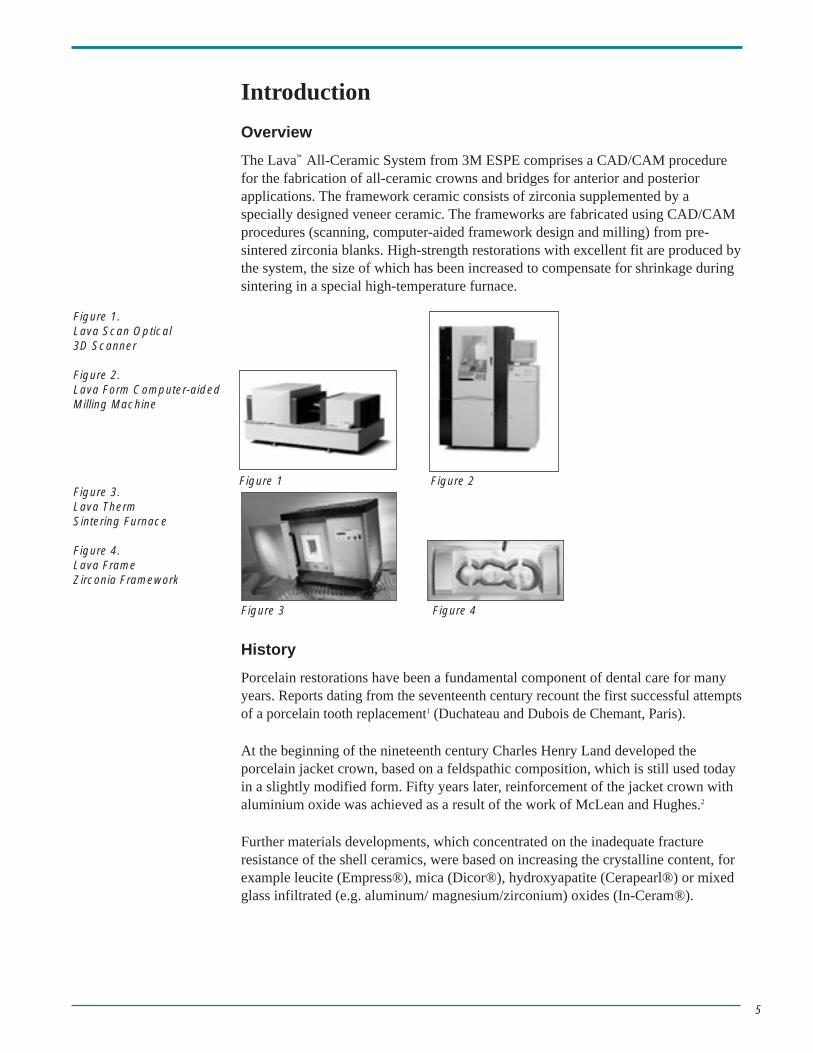
The Lava™ All-Ceramic System from 3M ESPE comprises a CAD/CAM procedurefor the fabrication of all-ceramic crowns and bridges for anterior and posteriorapplications. The framework ceramic consists of zirconia supplemented by aspecially designed veneer ceramic. The frameworks are fabricated using CAD/CAMprocedures (scanning, computer-aided framework design and milling) from pre-sintered zirconia blanks. High-strength restorations with excellent fit are produced bythe system, the size of which has been increased to compensate for shrinkage duringsintering in a special high-temperature furnace.
History
Porcelain restorations have been a fundamental component of dental care for manyyears. Reports dating from the seventeenth century recount the first successful attemptsof a porcelain tooth replacement1 (Duchateau and Dubois de Chemant, Paris).
At the beginning of the nineteenth century Charles Henry Land developed theporcelain jacket crown, based on a feldspathic composition, which is still used todayin a slightly modified form. Fifty years later, reinforcement of the jacket crown withaluminium oxide was achieved as a result of the work of McLean and Hughes.2
Further materials developments, which concentrated on the inadequate fractureresistance of the shell ceramics, were based on increasing the crystalline content, forexample leucite (Empress®), mica (Dicor®), hydroxyapatite (Cerapearl®) or mixedglass infiltrated (e.g. aluminum/ magnesium/zirconium) oxides (In-Ceram®).
Figure 1.Lava Scan Optical 3D Scanner
Figure 2.Lava Form Computer-aided Milling Machine
Figure 3.Lava Therm Sintering Furnace
Figure 4.Lava Frame Zirconia Framework
Figure 1 Figure 2
Figure 3 Figure 4

6
Pure polycrystalline oxide ceramics (e.g. Procera®) have only been in clinical use forabout 10 years.
Casting (Dicor®), pressing (Empress®) and grinding techniques (CEREC®) are allused to create morphology.
The idea of using CAD/CAM techniques for the fabrication of tooth restorationsoriginated with Duret in the 1970s. Ten years later Mörmann developed the CEREC-system first marketed by Siemens (now Sirona), which enabled the first chairsidefabrication of restorations with this technology. There has been a marked accelerationin the development of other CAD/CAM laboratory systems in recent years as a resultof the greatly increased performance of PCs and software.
Pressed ceramics, such as Empress have been used successfully for anterior crownapplications for more than 10 years. In-Ceram crowns have also been used with long-term success for anterior tooth applications, though In-Ceram bridges and fixedpartial dentures in posterior applications have not. In view of the success ofporcelain fused to metal for over 30 years, any new all ceramic system must havelongevity comparable to this. A minimum survival rate of 85 % after 10 years in situis required - even for posterior teeth.2a
Crowns luted utilizing adhesive bonding have initially had favorable conditions for a high survival rate. Adhesively bonded, glass containing restorations help dispersestress throughout the restoration/tooth structure system. The first published clinicalresults on Empress II are promising for bridges only up to the first premolar, butagain long-term results are not yet available.
Motivation
As a result of the requirement to provide patients with excellent esthetic andbiocompatible prosthetic dental restorations, the search for ways to fabricate all-ceramic multi-unit bridges, offering long-term stability in posterior applications, has witnessed the limitations of glass ceramics and infiltrated ceramics.
Because of their material characteristics, polycrystalline ceramic frameworks are able to surmount these limitations. Bridges for the posterior region are alsoconsidered as an indication. It is zirconium oxide (zirconia), with its excellentstrength and biocompatibility known from implant prosthetics, that providessuitability as the framework material of choice. This type of framework can befabricated by an automated process which supplies constant, monitored high quality,and is designed to be as versatile (in materials/indications) as possible.
Figure 5.Glass ceramic (contains glass) e.g. Empress I/II Ceramic
Figure 6.Infiltrated ceramic (contains glass). e.g. In-Ceram Ceramic
Figure 7.Polycrystalline ceramic(glass-free e.g. LavaCeramic)
Figure 5 Figure 6 Figure 7
10µm 10µm

7
The high strength and natural esthetics of the framework mean that less toothstructure is removed during clinical preparation. Traditional cementation techniques,as used in luting porcelain fused to metal, are possible.
Biocompatibility
All-ceramic tooth restorations are considered inert with respect to oral stability andbiocompatibility. The accumulation of plaque is comparable to that of the naturaltooth. Due to the low thermal conductivity of the ceramic, (unlike metal-supportedunits), sensitivity to temperature variation is not anticipated.
Long-term stability
The main concern centers on adequate long-term strength under functional stress inthe specified range of indications. From the clinical point-of view, it is not the initialstrength of the ceramic material itself that is of prime importance, but the longevityof the permanent restoration. In the case of ceramics containing glass, the type ofcementation, adhesive bonding or conventional, may be a decisive factor. It has aconsiderable effect on the stresses acting on the entire tooth preparation/restorationsystem. For the clinical use of all porcelains with a flexural strength of around 100MPa and fracture toughness < 2 MPa•m1/2 (typical for glass ceramics), adhesivebonding is required. In the case of polycrystalline ceramic frameworks withconsiderably higher strength values, conventional cementation using glass ionomercement may be recommended. Zinc phosphate cement is not indicated for estheticreasons.
The lack of long-term strength (subcritical crack growth, fatigue, stress, corrosion)for ceramic systems containing glass already on the market, when subjected to themasticatory forces occurring in the mouth, is problematical. There is more noticeableloss of strength with glass containing systems due to the effect of oral moisture andsubcritical crack propagation (decreases to < 50% of initial strength). To guaranteesuccessful, long-term muti-unit bridge restorations, an initial strength of more than400 N is required for anterior restorations and more than 600 N for posteriorapplications. Currently, values such as these (final strength of at least 500 N) arecurrently achieved only with alumina or zirconia bridges.2b
Traditional Working Method
Ideally, the laboratory’s dentist/customer needs a system that does not requirehim/her to change preparation and/or impressioning methods. The optimal systemwould use supragingival preparations where less tooth structure is removed, ascompared with porcelain fused to metal restorations. Traditional luting, e.g., glassionomer cement, would simplify the cementation process - and have the advantage of many years of success.
Range of indications
In modern clinical/materials scientific literature, currently available all-ceramicsystems (e.g. Empress® and In-Ceram®) are seen as being suitable for crowns inanterior and some posterior applications. Anterior bridges are indicated, but posterior

8
bridges may be suitable only as far back as the first premolar (e.g. Empress® II).4
Clearly, a need for a reliable all-ceramic system designed for use in all posterior aswell as anterior situations is needed.
Reliability
The literature describes other ceramic - specific parameters, such as fracturetoughness and Weibull modulus. The Weibull modulus indicates the distribution of strength values. A high Weibull modulus (> 10) reflects a close distribution and is therefore advantageous, especially if strength is low. However, for safety reasons ahigh Weibull modulus should be the goal even if there is high strength.
Accuracy of fit
Good accuracy of fit is also a determining factor for clinical success. An accuracy at the crown margin of 50 µm - 100 µm is considered ideal. A clear definition of theterm fit is important (Holmes et. al13).
Result
These requirements can now be achieved using precise scanning and millingtechnologies - coupled with accurate knowledge of zirconium oxide ceramics. 3M ESPE’s Lava™ system has been developed utilizing the accumulated knowledgeof previously available materials and systems, and newly developed state-of-the artscanning and milling expertise - to provide the laboratory, dentist, and patient withthe most durable and esthetic all - ceramic restorations available today.
9
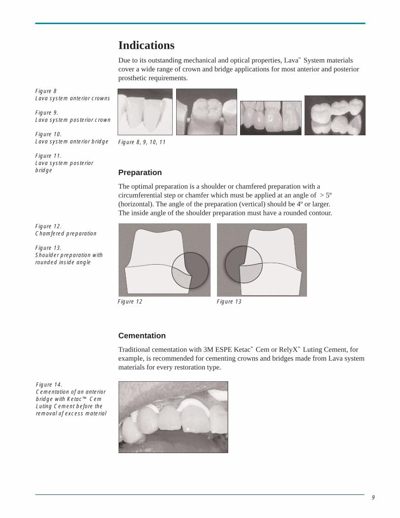
IndicationsDue to its outstanding mechanical and optical properties, Lava™ System materialscover a wide range of crown and bridge applications for most anterior and posteriorprosthetic requirements.
Preparation
The optimal preparation is a shoulder or chamfered preparation with acircumferential step or chamfer which must be applied at an angle of > 5º(horizontal). The angle of the preparation (vertical) should be 4º or larger. The inside angle of the shoulder preparation must have a rounded contour.
Cementation
Traditional cementation with 3M ESPE Ketac™ Cem or RelyX™ Luting Cement, forexample, is recommended for cementing crowns and bridges made from Lava systemmaterials for every restoration type.
Figure 8Lava system anterior crowns
Figure 9.Lava system posterior crown
Figure 10.Lava system anterior bridge
Figure 11.Lava system posteriorbridge
Figure 8, 9, 10, 11
Figure 12.Chamfered preparation
Figure 13.Shoulder preparation withrounded inside angle
Figure 14.Cementation of an anteriorbridge with Ketac™ CemLuting Cement before theremoval of excess material
Figure 12 Figure 13

10
Materials Science Background
General Overview
The general term all-ceramic dental materials covers various oxide ceramic with verydifferent material properties.
In addition to glass ceramics (reinforced by crystalline regions), two other typesavailable are glass infiltrated and polycrystalline ceramics.
The first two groups are multi-phase materials and contain crystalline constituents(e.g. leucite crystallites) in addition to an amorphous glass phase.
Alumina and zirconia are the only two polycrystalline ceramics suitable for use indentistry as framework materials, able to withstand large stresses in both anterior andposterior areas. These materials are shown to provide the necessary esthetic (toothshade, opacity/translucency) and materials properties required of a modern toothrestoration.
Literature6,7 indicates that 3-unit posterior bridges are clinically acceptable due to thehigh fracture toughness of In-Ceram® zirconia, as recommended by themanufacturer Vita™. It must be noted however, that finishing of sintered ceramicsinduces micro-defects. The introduction of defects during fabrication may lead to anoticeable loss of strength even with high strength systems. In particular, thephenomenon of subcritical crack growth results in a poorer long-term prognosis forfinished ceramic restorations. Generally speaking, the long-term strength of ceramicsystems containing glass cannot be classified as risk-free.
The question of long-term stability, which is highly dependent on subcritical crackpropagation and fatigue is an exceptionally important aspect in the assessment ofnew all-ceramic systems. Subcritical crack propagation refers to a continous fractureprocess in ceramics subjected to static and/or dynamic stress, whereby the crack maygrow at a certain rate, until it results in a complete failure. The speed of crack growthalso depends on the surrounding medium as well as the previously mentionedfracture toughness. H2O in the saliva leads to so-called stress corrosion in systemscontaining glass. The water reacts with the glass causing decomposition of the glassstructure; this leads to increased crack propagation velocities and consequently tolong-term strength issues. On the other hand, systems having a polycrystallinemicrostructure such as ZrO2 or Al2O3, and are to a great extent glass-free, displayexcellent long-term stability (see Properties and References).6,7
The preparation geometry and wall thickness of framework and veneer ceramic arealso decisive factors with regard to the strength of the permanent restorations. In thecase of In-Ceram a chamfered preparation and framework wall thickness of around0.8 mm is required for an optimal result. In the case of Empress®, the requirementsare 1 mm of reduction in the body of the preparation and the shoulder. Lava™ Frameframeworks demonstrate the required strength at an overall thickess of only 0.5 mm.
11
Materials Science Aspects
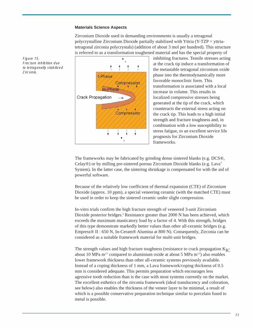
Zirconium Dioxide used in demanding environments is usually a tetragonalpolycrystalline Zirconium Dioxide partially stabilized with Yttria (Y-TZP = yttria-tetragonal zirconia polycrystals) (addition of about 3 mol per hundred). This structureis referred to as a transformation toughened material and has the special property of
inhibiting fractures. Tensile stresses actingat the crack tip induce a transformation ofthe metastable tetragonal zirconium oxidephase into the thermodynamically morefavorable monoclinic form. Thistransformation is associated with a localincrease in volume. This results inlocalized compressive stresses beinggenerated at the tip of the crack, whichcounteracts the external stress acting onthe crack tip. This leads to a high initialstrength and fracture toughness and, incombination with a low susceptibility tostress fatigue, to an excellent service lifeprognosis for Zirconium Dioxideframeworks.
The frameworks may be fabricated by grinding dense sintered blanks (e.g. DCS®,Celay®) or by milling pre-sintered porous Zirconium Dioxide blanks (e.g. Lava™
System). In the latter case, the sintering shrinkage is compensated for with the aid ofpowerful software.
Because of the relatively low coefficient of thermal expansion (CTE) of ZirconiumDioxide (approx. 10 ppm), a special veneering ceramic (with the matched CTE) mustbe used in order to keep the sintered ceramic under slight compression.
In-vitro trials confirm the high fracture strength of veneered 3-unit ZirconiumDioxide posterior bridges.8 Resistance greater than 2000 N has been achieved, whichexceeds the maximum masticatory load by a factor of 4. With this strength, bridges of this type demonstrate markedly better values than other all-ceramic bridges (e.g.Empress® II : 650 N, In-Ceram® Alumina at 800 N). Consequently, Zirconia can beconsidered as a suitable framework material for multi-unit bridges.
The strength values and high fracture toughness (resistance to crack propagation KICabout 10 MPa m1/2 compared to aluminium oxide at about 5 MPa m1/2) also enableslower framework thickness than other all-ceramic systems previously available.Instead of a coping thickness of 1 mm, a Lava framework/coping thickness of 0.5mm is considered adequate. This permits preparation which encourages lessagressive tooth reduction than is the case with most systems currently on the market.The excellent esthetics of the zirconia framework (ideal translucency and coloration,see below) also enables the thickness of the veneer layer to be minimal, a result ofwhich is a possible conservative preparation technique similar to porcelain fused tometal is possible.
Figure 15.Fracture inhibition due to tetragonally stabilizedZirconia.

12
The surface finishing of ceramic materials has a decisive effect on the material’sflexural strength. The grinding and milling of sintered ceramics usually leads to areduction in strength (micro-defects on the surface). The finishing, by grinding ormilling, of sintered zirconia frameworks (either by means of the fabrication process,such as DCS, or finishing in the dental laboratory) may lead to a loss of strengthcompared to finishing in the green, or pre-sintered state (Lava™ system, 3M ESPEtechniques). The finishing of sintered frameworks using grinding or milling tools iscontra-indicated in the connector area. (enhanced tensile stress). The millingprocedure sufficiently ‘roughens’ the internal aspect of the crown for retention ofcement.
If adhesive bonding is desired, it must be accomplished with the aid of 3M ESPE’sRocatec™ Bonding System or Cojet™ Bonding Systems, which add a silicate coatingto the internal aspect of the framework, followed by a dual cure bonding resin, suchas the RelyX™ ARC Adhesive Resin Cement.
Zirconia posterior bridges fabricated according to procedures similar in Zurich havebeen in use in a clinical trial since 1998. Results so far are extremely positive.9a, 9b
Properties
Overview
Zirconium Dioxide has proven itself as a biocompatible material in implant surgerysince the 1970’s. The Lava System with Frame zirconia demonstrates no measurablesolubility or water absorption. Therefore the strength of this material even after along period in the mouth is expected to be excellent. The Lava system with Framezirconia has no allergenic potential and is very biocompatible and Lava system withCeram veneer ceramic has all the familiar advantages of a feldspathic veneer ceramicwith respect to biocompatibility and abrasion characteristics.
Zirconia withstands many times the level of stress occurring in the mouth (loadsmeasured for: anterior teeth up to 250 N, posterior teeth up to 450 N). Its strength isconsiderably higher than other all-ceramic materials. Unlike infiltrated or glassceramics, the Lava system with Frame zirconia is particularly suitable for posteriorbridge frameworks.

13
Mechanical Properties
Material Specifications
Lava™ Frame framework ceramic
Density (ρ): 6.08 g/cm3
Weibull strength (σB): > 1200 MPa
Fracture toughness (KIC): 10 MPa m1/2
(Youngs) Modulus of elasticity (E): 210 GPa
CTE: 10 x 10-6 25-500°C
Melting point: 2700°C
Grain size: 0.5 µm
Vickers hardness (HV 10): 1250
Lava™ Ceram veneer ceramic
Density (ρ): 2.5 g/cm3
Weibull strength (σB): 95 MPa
Fracture toughness (KIC): 1.2 MPa m1/2
(Youngs) Modulus of elasticity (E): 80 GPa
CTE: 10x10-6 25-500°C
Firing temperature: 810 °C
Grain size (d50): 25 µm
Vickers hardness (HV 0.2): 530
Data in accordance with standard ISO 6872
Material Specifications - Lava Frame framework ceramic
4-point bending test (biaxial: piston-on-three-balls)
A competitive product, In-Ceram®Zirconia, which is a glass-infiltratedceramic based on a zirconium oxideand aluminium oxide combination, hasonly about half the flexural strength ofLava System Frame, but has beenindicated for bridges in posteriorapplications.
The flexural strength (ISO 6872) in the 3-point bending test was also determined byDr. Simonis (Berlin)10: 1625 MPa.
Data in accordance with standard ISO 6872
Lava Frame
In-Ceram ZirconiaVita
In-Ceram AluminaVita
Empress II Ivoclar
Empress Ivoclar
0
200
400
600
800
1000
1200
1400
Fle
xura
l Str
engt
h, M
Pa
1272
530
350265
130

14
Chemical Solubility
The fact that there is no detectablesolubility of the LavaTM zirconium oxideframework is an indication of its highbiocompatibility.
Data in accordance with standard ISO 6872.
Material Specifications - Lava Ceram veneer ceramic
Chemical Solubility
As with the framework ceramic, here toothe solubility cannot be measured. This isan indication of excellentbiocompatibility.
Long-term strength
Ceramic Weibull Weibull Fracture Crack Crackstrength σ0 modulus m toughness growth growth
[MPa] [ - ] KIC coefficient n coefficient B [MPa√m] [ - ] [MPa2sec]
Lava™ System Frame 1345 10.5 9,6 50* -
In-Ceram® Alumina 290 4.6 5 18 6.0·101
CEREC® (Vita™ Mark II) 88 24 1.3 26 1.8·101
Dicor® 76 6 0.8 25 2.9·101
Empress® I 89 9 1.2 25 5.8·101
Empress® II 289 9 2.5 20 2.3·103
HiCeram® 135 9 2.5 20 1.2·103
Hydroxyapatite 114 6 0.9 17 2.2·102
Vita™ Omega Opaker 69 12 1.4 21 7.2·101
Prof. Marx and Dr. Fischer, Aachen.19
* = 3M ESPE internal data
In-Ceram AluminaVita
In-Ceram ZirconiaVita
Empress Ivoclar
Empress II Ivoclar
Lava Frame
0
400
800
1200
1600
2000
Sol
ubili
ty, µ
g/cm
2
1805
805
110 900
Vitadur-Alpha Vita
enamel
Empress Ivoclarenamel
All-CeramDuceraenamel
Empress II Ivoclarenamel
Lava Ceram0
10
20
30
40
50
60
Sol
ubili
ty, µ
g/cm
2
55
46
16
6
0
Table 1: Characteristic materialvalues of various dentalceramics

15
Estimate of long-term strength of the Lava™ System Frame(peripheral conditions: 60 % atmospheric humidity, 22°C, static continuous load)
A mathematical estimate of the service life time (maximum static continuousloading, with 2% failure rate after 5 years) can be made using a so-called SPTdiagram (SPT: Survival-Probability-Time):
Lava™ System Empress® II In-Ceram® Vita™ Frame Alumina Mark II
σ2% 5 years [MPa] 615 80 125 30
Source: Marx and Fischer, Aachen and internal measurements
The table must be interpreted in the following way: if a Lava System Frame testspecimen is subjected to a load of 615 MPa in moisture for 5 years, a failure rate of2% may be expected. The same failure rate is returned by Empress II under acontinuous load of only 80 MPa.
Strength and Real GeometriesFracture strength of 3-unit posterior bridges (patient models) before and after masticatory
simulation (Munich, Prof. Pospiech PD, Dr. Nothdurft, Dr. Rountree)10,11
Resiliently mounted after cementation with Ketac™ Cem Luting Cement (meanvalues of 8 bridges)
a) initially after 24 h: 1800 N SD = 234N
b) after 1.2 million masticatory load cycles (50N) and 10,000 thermocycles (5°/55°C): 1450 N SD = 235N
The slight decrease in the values combined with exceeding the maximum masticatoryloading for posterior teeth of approx. 450 N (see above) after simulated 5 years ofwear suggests an excellent probability of survival.
Table 2: Long-term flexural strength(static continuous load)
Figure 16.Set-up for masticatorysimulation and thermocycle
Figure 17.Fracture test
Figure 16 Figure 17

16
Fracture strength and long-term strength of 3-unit anterior bridges before and aftermasticatory simulation (Kiel, Prof. Ludwig)10
Resiliently mounted after cementation with glassionomer. 6 bridges (11-22) were loaded from an angleof 30° until fracture occurred.
a) Initially (24 h storage in water): static fracture load: 1430 N
b) Long-term strength after masticatory simulation (1.2 million cycles –corresponding in clinical terms to approx. 5 years of wear, at 250 N, incl.thermocycling 5°/ 55°C): no fracture
Prof. Ludwig’s conclusion based on the maximum masticatory force on the anteriorteeth of 180 N: Lava™ System anterior bridges can be assumed to be clinicallyresistant to fracture in long term usage.
Abrasion
In a masticatory simulator in Erlangen (Lohbauer), hemispheres made from theveneer ceramics under examination were tested against bovine enamel. Lava Ceramwas compared with Empress® II and Omega 900® (spherical) against bovine enamel(ground flat), and also Lava™ Ceram against itself.
The analyses were carried out using a scanning electron microscope (SEM) both forthe spheres and the specimens, and volumetric surveys were conducted.
The wear values after 200,000 cycles with a load of 50 N and a further 1,500 cyclesunder thermocycle (5°C and 55°C) also with a load of 50N resulted in a mean wearof 10-3 mm3 for all veneer ceramics.
Other findings:
• Differences between the individual groups cannot be established to asignificant degree.
• The abrasion of two ceramic surfaces in contact is higher in comparison withthe bovine enamel.
• The traces of abrasion on the spheres are very slight and lie within the sameranges of size amongst the groups.
• Fractures which can be detected on the bovine enamel samples on the SEMimages are natural fractures in the enamel—and are not attributable to theabrasion process.
The Lava Ceram veneer ceramic displays no fundamental differences from othercommercially available products examined as far as abrasion is concerned.
Figure 18.Measurement of staticfracture load

17
Visual Properties/Esthetics
The Lava™ System Ceram range of veneer ceramics is optimally coordinated to therange of shades which are applied to the Lava System framework. This results in aharmonic color effect and natural blending to the oral environment (adjacent naturaldentition).
The ideal translucency results from the material properties and the low wall thicknessof the sintered zirconia. No light-absorbent opaquer or opaque dentine layers arenecessary for the build-up of Lava all-ceramic restorations.
Moreover, the relatively thin framework permits optimal build-up even in difficultsituations. An appropriate selection of unique modifiers rounds off the Lava™ SystemCeram range.
The framework can be colored in 7 shades in the Vita™-Classic shade system and istherefore ideal for a natural-looking build-up.
The relative translucencyof Lava framework andEmpress® II frameworkis comparable even inview of the wall thick-nesses recommended bythe manufacturers (Lava:0.5 mm; Empress II: 0.8mm).
Any tooth shade can be reproduced without difficulty using the traditional range of16 shades. Effect material and extrinsic colors provide limitless customization.
Figure 19.After the coloring of theframework (the first unit hasnot been colored)
Figure 20.Comparison of translucencyas a function of wall (coping)thickness
Figure 21.Lava System Anterior bridgefrom tooth no.s 6-8

18
Accuracy of Fit
Lava™ crowns and bridges have excellent accuracy of fit.
In the Lava System fabrication procedure, the crown or bridge framework is milledfrom a so-called “green” state. This green blank is made from presintered zirconiaand is therefore considerably softer than dense (fully sintered) material. Milling isperformed quickly, accurately, and economically before the extreme strength isachieved during the final sintering.
Excellent fit is achieved due to the high milling accuracy and the accurate calculationof the sintering shrinkage via the software package. The cement gap can be adjustedto the individual requirements.
Control of this procedure provides one of the fundamental innovations of the LavaSystem technique. Specific 3M ESPE technology and sophisticated productionprocesses for the presintered blanks ensure accuracy of fit. The dimensions of themarginal gap easily achieve values comparable to those of porcelain fused to metal.
Studies of marginal gap measurements produced values of 40 µm or 70µm for MO orAMO.12
MO (marginal opening) can be interpreted as the distance between the frameworkand the preparation close to the crown margin. AMO (absolute marginal opening)also includes possible contouring work above and below, and measures the distancebetween the end of the crown margin and the preparation margin.13
Figure 22.Light-optical microscopeexposure: cross-section of a3-unit bridge from no.s 18-20
Figure 23.Detail enlargement buccal
Figure 24.Detail enlargement mesial
Figure 25.MO with under-extensionFigure 26.AMO with under-extension
Figure 25 Figure 26

19
Biocompatibility
Another remarkable feature of zirconia, in addition to its extraordinary chemicalstability, is its very high level of biocompatibility. For this reason it has already been in use for more than a decade as a material for surgical implants, such as hipjoints. The zirconium oxide utilized, and likewise the veneer ceramic, manifests nomeasurable solubility or allergic potential, and produces no irritation of the tissue.
The lower thermal conductivity provides comfort for the patient. Moreover, Lava™
System materials do not contribute to galvanic processes in situ.
Clinical ResultsMore than 600 cases of fixed dental prosthetic work utilizing Lava system materialswere placed between December 1999 and August 2001. In addition to crowns(approx. 500) and anterior bridges (approx. 20), 100 posterior bridges are in situ.
Some patients were treated in 3M ESPE’s own dental practice (Seefeld Center). The majority of the clinical work was carried out in various 3M ESPE consultantlaboratories and tested on their dentist/clients (40 dentists in total) with verysatisfactory results. The esthetics, precision fit, and suitability for simpleconventional cementation were found to be particularly impressive.
In addition to this, Dr. Peter Pospiech, senior physician and professor of dentistry atthe University of Munich has been conducting a clinical survey according to EN 540(ISO 14 155) since summer 2000. In this study, 35 patients fitted with posteriorbridges are being monitored for a period of 5 years.
Figure 27.3-unit posterior bridge no.s29-31 P. Pospiech,University of Munich

20
Technical Overview
Working model Scanning Designing
Milling Sintering Veneering
Scanning with Lava™ Scan:
The unit consists of the non-contact, optical scanning system Lava Scan (white lighttriangulation), a PC with monitor and the Lava CAD software.
When the sectioned model has been positioned in the scanner, individual prepar-ations and the ridge are recorded automatically and displayed on the monitor as athree-dimensional image (recording of the model situation including preparations,gingiva and occlusal record). The preparation margins are scanned and displayedautomatically.
CAD Modelling with Lava™ CAD:
The design of the framework on the screen, e.g. the insertion of a pontic (from alibrary) or the design/modelling of the connections is done with the keyboard, mouseand software support. No special knowledge is necessary. The data is then transferredto the Lava Form milling unit for calculation of the milling path.
Figure 28.Design of connectors andpontic on the screen

21
Milling with Lava™ Form:
The 3D shape is milled from a pre-sintered ZrO2 blank using hard metal tools. Theaverage milling time for a crown is 35 minutes, for a 3-unit bridge about 75 minutes.The machine has a magazine capacity of 20 blanks; new blanks can be inserted andfinished frameworks removed while milling continues. Different frameworks can bemilled automatically, even overnight, thanks to the automatic tool changer.
Sintering in Lava™ Therm:
Manual finishing can be carried out before sintering takes place. The coloring of theframeworks also takes place before the sintering process according to the prescribedshade (7 possible shades, keyed to Vita™ Classic). The fully-automated, monitoredsintering process then takes place with no manual intervention in a special furnace,the Lava Therm (approx. 8 hours including heating up and cooling phases).
Veneering with Lava™ Ceram:
The coefficient of thermal expansion (CTE) of the specially developed, integratedoverlay or porcelain ceramic system has been matched closed (-0.2 ppm) to that ofzirconia. The 16-shade system is based on the Vita-Lumin range. Very estheticcharacterizing possibilities are possible by various additional individual materials.The natural translucency harmonizes ideally with the translucent zirconium oxideframework.
Figure 29.Manual finishing before sintering

22
Instructions for Use
The Framework Ceramic
Lava™ FrameZirconia Blanks for Framework Production with Lava Form
Product Description
Lava Frame comprises a selection of Zirconia blanks for fabrication of frameworksfor all-ceramic restorations. The blanks are processed in the Lava Form CAD/CAMsystem. After milling and before sintering, the frameworks are colored with one of 7available Lava Frame Shade tinting liquids as required to achieve the desired toothcolor. The colored frameworks are then sintered using a specialized program in theLava Therm sintering furnace.
• Please retain these instructions for future use.
Areas of Application
Precisely fitting all ceramic restorations can be fabricated only when toothpreparation guidelines are followed. For pertinent information, please refer to the“Information for Dentists” section of the Lava system’s Instructions for Use.
• Fabrication of all-ceramic crowns and 3-unit bridge frames for anterior andposterior teeth.
Model Preparation
• A light colored gypsum laboratory stone is recommended for models.
• All segments of the saw cut model must be removable and double pinned toavoid rotation
• An Appropriate holder must be used. Use magnetic base type retention forthe working model – do not use indexed casts.
• Dies should be ditched below the margin – DO NOT mark margins or use diespacer and/or hardener on dies.
• Undercuts and defects are blocked out with block-out wax.
• Reflective areas on the abutments are detrimental to the scanning procdure.Use titanium dioxide spray to ‘dull’ surfaces of the die. (e.g. Developer D70,Met-L-CHEK).
Scanning
Crowns and bridges are designed after the scanning-procedure with the Lava Scancomputer.
The strength of the restoration and accurate milling results depend on the design ofthe various bridge elements, the crown margins design, and proper positioning of thesprues.

23
• When entering data into the Lava™ Scan computer, please observe the designguidelines described in the Operating Instructions of the Lava System!
Preparation of the Milling Unit
• To mill frameworks with the Lava Form CAD/CAM facility, use burs of type4 (rough milling), type 5 (finishing), and type 6 (fine-finishing) only; seealso Lava Form Operating Instructions.
• Prior to processing Lava Frame frameworks, clean the milling chamber ofthe Lava Form milling unit. Make sure that no oil remains on or is fed to thecutting spindle and all metal and/or plastic dust is removed.
Processing After Milling
NOTE: Dust from grinding may cause eye and respiratory system irritation. Wear protectivegoggles. Use with appropriate local exhaust ventilation; in situations where local exhaustventilation is not adequate, wear appropriate respiratory protection.
In order to prevent contamination, the blank must not be exposed to water or anyother liquids or oils during processing!
Removal of the Milled Framework from the Holding Device
We recommend the use of a high speed air turbine handpiece to remove theframework – due to the lower degree of vibration as compared to other handpieces!If no turbine is available, fine cross-cut tungsten carbide burs can also be used -rotary speed 20,000 rpm.
• First, notch all sprues on their top as close as possible to the crown from theocclusal side and then carefully extend the notches from the opposite side toseparate the framework. Use as little pressure as possible in removing theframework from the sprues! Place gently in hand or soft pad! Too muchpressure or rough handling may cause damage.
Finishing of the Blank Surface
Compared to finishing sintered frameworks, shape correction and surface adjustmentof the green body (soft-sintered framework) is a more simple and reliable procedure.Adjusting sintered frameworks may cause damage invisible to the naked eye. Sharpcorners, edges, joints of the holding pins, and all areas on the surface should besmoothed prior to sintering.
NOTE: The presence of notches and sharp edges or damage on the bottom side of theinterdental connections may substantially reduce the strength of the sintered framework. It isessential to make the framework surface smooth prior to sintering!
Use Universal Polishers from Brasseler (Type Komet #9557) for finishing only -rotary speed 10,000 - 20,000 rpm!
• Take care not to damage the crown margin when finishing the outer contourin the vicinity of this area.

24
Cleaning of the Framework
• Touch the framework only with clean, non-oily hands. The frameworksurface must remain uncontaminated.
• Thoroughly remove milling dust and debris from the entire surface of theframework, including the internal surfaces of the abutment copings with adisposable applicator. To ensure even coloring, the framework must be clean,free of oils, and completely dry prior to coloring.
Coloring of the Framework
Preparation of the Coloring Liquid/Coloring Process
All immersion containers for the framework must be dry, clean, and free from (old)coloring liquid to ensure an even shading throughout the framework.
• Select an immersion container that is large enough so the framework will notcome in contact with the sides of the container.
• Select the suitable Lava™ Frame shade coloring liquid for the desired toothshade:
300 ml – bottles
Lava Frame Shade FS 1 FS 2 FS 3 FS 4 FS 5 FS 6 FS 7Coloring Liquid
Coodinates with A 1 B 2 A 2 A 3.5 B 3 C 2 D 2Vita Classic Colors B 1 C 1 A 3 A 4 B 4 C 3 D 3
C 4 D 4
• Shake up the Lava Frame shade coloring liquid prior to use!
• Pour a sufficient amount of coloring liquid into the container to ensure thatthe framework is covered by 3 mm of liquid.
• Reseal the bottle immediately after use to ensure that the concentration of theliquid does not become altered.
Coloring Process
• Use plastic forceps to gently place the framework in the container. Theframework must be completely covered by the coloring liquid!
• Carefully rock the container to allow any air bubbles trapped inside thecoping to escape.
• The immersion time is 2 min. Once this period has elapsed, use clean plasticforceps to remove the framework from the liquid.
• Color each framework only once !
• To ensure even, shading any excess coloring liquid must be blotted from thecoping and the connections, e.g. with an absorbent paper towel.
• Make sure that no paper towel remains on the framework.

25
• After coloring of the framework, place it on a furnace stand for sintering andput it into the furnace. The sintering process starts only after the furnancedoor is closed.
• Used coloring liquid is a US EPA hazardous waste. Consult Material SafetyData Sheet for disposal information.
Sintering of the Lava Framework
Positioning for Sintering
As the Lava framework shrinks by approx. 20-25% (linear) during the sinteringprocess, it is essential to position the framework so that its shrinkage is not restrictedduring the sintering process. The framework must be positioned so that it cannot tipover and does not touch other adjacent frameworks, and is freely suspended on thepegs so that it does not distort during the sintering process.
• Place the pegs or wires on the honeycomb sintering tray as is required by theframework geometry. The framework must be able to move freely asshrinkage occurs.
• Do not place more than one sintering peg or wire into hole of the honeycombtray.
Positioning of Copings for Sintering
• Depending on type, use 1 to max. 4 pegs per coping.
Number of sintering pegs
Anterior tooth 1
Premolar 2
Molar 3 - 4
Positioning of Bridges for Sintering
• Position bridges perpendicular to the furnace insertion direction.
Anterior Bridges (13-23, 33-43)
• Always position bridges using one peg per coping.
• The pegs must be positioned close to the walls of the abutment copingnearest the pontic (Mi and Di) without touching them.
Posterior Bridges (13-17, 23-27, 33-37, 43-47)
• Generally position bridges on two wires in the connector area (one perconnector).
• Generally position bridges with the occlusal aspect up.

26
Sintering
For information on the operation of the sintering furnace, please refer to theOperating Instructions of the Lava™ Therm unit!
• For an optimal use of space, the furnace can be loaded with two sinteringtrays on top of each other. Close the door before pressing “START”.
• Once the Start button is pressed, the sintering program starts upautomatically and heats the furnace to 1,500°C/2,732°F. The sintering time isapprox. 11 hours. The furnace is automatically unlocked once thetemperature drops below 250°C/482°F during the cooling phase of thefurnace.
NOTE: Contact with hot surfaces and material may cause thermal burns. Avoid contact withhot surfaces and material. Wear appropriate insulating gloves when handling hot material. Incase of contact, seek medical attention.
• If the temperature is above 250°C/482°F, do not force the furnace door opensince the resulting extreme drop in temperature may damage the furnaceand/or the frameworks!
• Use tongs to remove the sintering tray from the furnace. Place the sinteringtray on a refractory surface and allow the frameworks to cool down slowlyon the sintering tray.
Veneering
For veneering use Lava Ceram veneer ceramic, a product specifically developed foruse with Lava Zirconia framework material. See Instructions for Use of Lava Ceramwhen processing!
Cementation
DO NOT roughen the internal surfaces of crowns by mechanical means.
DO NOT use light-curing glass ionomer cements, as water sorption may cause thecement to expand after placement in situ.
For detailed information on the products mentioned in the following, please refer tothe corresponding Instructions for Use!
Temporary Cementation
If a composite resin cement is used for permanent cementation:
• For temporary cementation use eugenol-free temporary cement. Residualeugenol-containing products may inhibit the setting of composite resincements during the permanent cementation process!
If a conventional cement is used for permanent cementation:
• Use a common commercial temporary cement.

27
Conventional Cementation
For cementing, use conventional 3M ESPE KetacTM Cem Glass Ionomer Cement orRelyX™ Luting Cement. The use of phosphate cements are not indicated for use withLava™ restorations.
Adhesive Cementation
The strength of Lava Frame frameworks is high. Adhesive cementation does notprovide significant mechanical advantages as the Lava material can neither be etchednor directly silanated.
For adhesive bonding, the Lava restorations internal surfaces must be silicated with3M ESPE Rocatec™ Soft or Cojet™ Sand, and then silanized with ESPE™ SIL Silaneor RelyX™ Ceramic Powder. For details on processing, please refer to the Instructionsfor Use of the Rocatec System or Cojet Sand.
Use of the Rocatec System in the Laboratory:
• The restoration can be tried in, if desired.
• Then silicate the internal surfaces of the restoration with Rocatec Soft.
• Apply ESPE SIL or RelyX Ceramic Powder coupling agent and allow to dry.
• Soon thereafter, place in the mouth with RelyX™ ARC Adhesive ResinCement. Please follow Instructions for Use.
Use of Cojet Sand in the Dental Office:
• First, try in and then silicate the surfaces with Cojet Sand.
• Apply ESPE-Sil or RelyX Ceramic Powder primer and allow to dry.
• Soon thereafter, place in the mouth with composite attachment cementRelyX ARC adhesive resin cement.
• Follow the corresponding Instructions for Use.
Removal of a Seated Lava Restoration
To remove a seated restoration, use appropriate, water cooled rotary instruments toslit restoration though ceramic. Use appropriate instrumentation to removerestoration from tooth structure.

28
Troubleshooting Common Problems
Error Cause Solution
Framework shows Coloring liquid did All excess coloring liquid mustspots after coloring. not dry evenly. be removed very carfully by
blotting with tissue.
Coping breaks during Holding pin was separated Separate closer to milledremoval from the Lava from milled framework framework to reduceFrame blank (after Milling). too far away from framework vibrations.
surface.
Bur “wobbles“ in Check the handpiece turbine. handpiece chuck.
Bur is dull. Use a new bur.
Framework does not Movement (shrinkage) Ensure proper positioning fit working model. during sintering is restricted during sintering as described
by abutments binding on under “Positioning for sintering stands. Sintering”.
Die was not oriented to the Prior to scanning, checkcorrect position on the model the proper positioning/ during scanning. orientation of the die on
working model.
Contamination is Coloring liquid is Use coloring liquid only once!apparent on the coping contaminatedsurface due to repeated use.
Whitish spots are Milling dust was not removed Carefully remove all milling apparent on the coping from coping prior to coloring dust prior to coloring.surface and sintering.
Storage and Shelf Life
Do not store the Lava™ Frame shade coloring liquid above 25°C/77°F. Avoid directexposure to sunlight.
Do not use after the expiration date.
Packaging
12 Crown blanks
12 Bridge blanks, 3-unit
300 ml Lava Frame shade coloring liquid each of the following colors: FS1, FS2, FS3, FS4, FS5, FS6, FS7
1 Sintering tray
1 Sintering box
Date of the Information 08/01

29
The Veneer Ceramic
Lava™ Ceram Veneer ceramic for Lava Frame zirconium oxide frameworks
Product Description
Lava Ceram veneer ceramic and the Lava Frame work ceramic are components ofthe Lava system, for the fabrication of all-ceramic restorations. Frame and veneerceramic have been specially developed to complement each other and cannot becombined with other ceramic materials.
Lava Ceram ceramic is available in 16 Vita™ shades. The color range comprises the following components: 7 shoulder materials, 16 framework modifiers, 16 dentinematerials, 10 Magic intensive materials, 4 incisal materials, 2 enamel effectmaterials, 4 Transpa-Opal materials, 1 Transpa-Clear material, 10 extrinsic colors, 1 glaze and the accompanying mixing liquids.
Please retain these instructions for future reference.
Preparation of Lava Frameworks prior to veneering with Lava System
Framework preparation
• Clean the colored and sintered framework in an ultrasonic bath. The framework must be absolutely clean and contaminant free!
Shade Selection
Combination table in accordance with Vita-Classic shades
VITA-Classic A1 A2 A3 A3.5 A4 B1 B2 B3 B4 C1 C2 C3 C4 D2 D3 D4
Shades
7 shoulder SH 1 SH 3 SH 3 SH 4 SH 4 SH 1 SH 2 SH 5 SH 5 SH 2 SH 6 SH 6 SH 6 SH 7 SH 7 SH 7
materials
16 framework MO MO MO MO MO MO MO MO MO MO MO MO MO MO MO MO
modifiers A1 A2 A3 A3.5 A4 B1 B2 B3 B4 C1 C2 C3 C4 D2 D3 D4
16 dentine D D D D D D D D D D D D D D D D
materials A1 A2 A3 A3.5 A4 B1 B2 B3 B4 C1 C2 C3 C4 D2 D3 D4
4 incisal E 2 E 2 E 3 E 3 E 4 E 1 E 1 E 3 E 3 E 4 E 3 E 3 E 4 E 4 E 3 E 3
materials

30
Shade table
Shoulder materials: Framework modifiers: Dentine materials: SH 1 – SH 7 MO A1 – MO D4 D A1 – D D4
Incisal materials: Enamel effect materials: Transparent-Opal materials:E 1 – E 4 E 5 Polar T 1 neutral
E 6 Sun T 2 yellowT 3 blueT 4 grey
MagicIntensive materials: Extrinsic colors: Glaze material:I 1 Ocean blue S 1 Ocean blue GI 2 Atlantis S 2 Atlantis I 3 Chestnut S 3 Chestnut Transpa- Clear:I 4 Havanna S 4 Havanna CL I 5 Orange S 5 OrangeI 6 Khaki S 6 KhakiI 7 Vanilla S 7 VanillaI 8 Honey S 8 HoneyI 9 Gingiva S 9 GingivaI 10 Violet S 10 Violet
• Prepare the required materials in accordance with the tooth shade.
Building a crown
Mixing
The following mixing liquids are available:
• Modelling liquid
• Shoulder material liquid
• Extrinsic colors liquid
• Mix the materials and the appropriate liquid to a creamy consistency using aglass or agate spatula. The mixing proportions by weight are 2.5 g powdercomponent to 1 g liquid.
Layering shoulder materials
If the framework is designed for shoulder material firing or the margin has been inadvertentlydamaged, shoulder material firing is required.
• Use shoulder material appropriate to the tooth shade and mix with shouldermaterial liquid.
• Isolate the model (die) with commercially available seperator.
• Place the framework on the model (die).
• Model the shoulder material on the die as necessary
• Remove the framework from the model and fire the finished shoulder asdescribed under “Firing.”

31
• Compensate for the sintering shrinkage by a second shoulder material firing,if necessary.
Application of framework modifier
The framework modifier gives the bridge framework its basic color.
• Mix the framework modifier with modeling liquid.
• Apply a thin coat (0.1 – 0.2 mm) to the entire surface of the framework to bevenerred.
• To achieve satisfactory wetting, vibrate gently and blot to avoid bubbleentrapment
• If desired, apply magic intensive shades to the framework with a dampbrush, or mix with framework modifier as necessary.
• Fire the framework modifier separately (procedure as for “First firing”) orapply the dentine layer directly to the unfired framework modifier.
Dentine/incisal layering
• Mix dentine, incisal materials and transparent materials with modellingliquid and build as required.
• Dentin, incisal, and Transpa shades are also layered and/or mixed asnecessary.
– Because of their intensity only use magic shades in small quantities.
• Before the first firing separate bridge units interdentally, to the framework.
• Carry out the first firing in accordance with the firing table, see “Firing”.
– The ceramic does not have to be roughened or sandblasted afterwards.
• If necessary, correct the shape with fine-grained diamond bur at low RPM.
– Under no circumstances must the framework be sectioned interdentally!
• Complete the restoration with additional firings as necessary to achieve finalform.
• Carry out the corrective firing in accordance with the firing table, see“Firing.”
Finishing
NOTE: Dust from grinding may cause eye and respiratory system irritation. Wear protectivegoggles. Use with appropriate local exhaust ventilation; in situations where local exhaustventilation is not adequate, wear appropriate respiratory protection.
• Finish with fine-grain diamond bur at low RPM.
• Use diamond discs to separate the veneer ceramic only, not the framework!
– Under no circumstances must the framework be damaged interdentally,otherwise a fracture of the restoration may result!
• Characterize the surface with rotary instruments as required.

32
• Apply shade characterizations with a mixture of extrinsic colors (stains) andglaze material. Glaze may also be applied separately in a thin layer.
• The final glaze firing is completed in accordance with the firing table, see“Firing.”
Firing
Start Drying t b t b Final Hold time Hold timetemp. time under without temp. under without
vacuum vacuum vacuum vacuum
1.+ 2. 450°C 4 mins 45°C/min - 830°C 1 min - Shoulder material firing
First dentine 450°C 6 mins 45°C/min - 810°C 1 min -and incisal firing
Second dentine 450°C 6 mins 45°C/min - 800°C 1 min - and incisal firing (corrective firing)
Glaze firing with 480°C 2 mins - 45°C/min 790°C - 1 minglaze material or extrinsic color
Glaze firing 480°C 2 mins - 45°C/min 820°C - 1 min without glaze material or extrinsic color
These temperatures should be used as a guide. Make adjustments as necessary toaccommodate variations in furnaces.
Intraoral repair of a veneer
Veneers of fixed restorations may be repaired using the Cojet™ System and a restorativecomposite.
• For information on use please refer to the Cojet System instructions for use.
Avoiding errors during use
Voids in the veneer layer
Voids may occur due to the generally known causes, but are also produced by improperlyapplied framework modifier. In such cases the framework modifier has not wetted theframework adequately and “lift-off” of the modifier layer may result.
• To achieve satisfactory wetting,vibrate gently and blot as necessary.
Storage and shelf-life
Do not store the liquids at temperatures exceeding 25°C/77°F.Do not use after the expiration date on the package.

33
Types of packs
Master Set
7 Shoulder materials, 15 g, SH 1 – SH 716 Framework modifiers, 15 g, MO A1 – MO D416 Dentine materials, 15 g, D A1 – D D44 Incisal materials, 15 g, E 1 – E 42 Enamel effect materials, 15 g, E 5 + E 64 Transparent-Opal materials, 15 g, T 1 – T 410 magic Intensive materials, 5 g, I 1 – I 1010 Extrinsic colors, 5 g, S 1 – S 101 Glaze material, 15 g, G1 Transpa-Clear material, 15 g, CL
Single packs
50 g powder component per shade:Shoulder materials, SH 1 – SH 7, Framework modifiers, MO A1 – MO D4Dentine materials, D A1 – D D4Incisal materials, E 1 – E 4Enamel effect materials, E 5 or E 6Transparent-Opal materials, T 1 – T 4Transpa-Clear material, CLGlaze material, G
5 g powder material per shade:Extrinsic colors, S 1 – S 10 Magic Intensive materials, I 1 – I 10
Date of issue 03/01

34
Questions and Answers
How comprehensive is the clinical experience with the 3M ESPE LavaTM System?The first fixed prosthetics utilizing Lava zirconia were cemented at the end of 1999.By August 2001 there were more than 600 cases in situ, about 100 of them posteriorbridges. But it must be remembered that this is the first time that an all-ceramicsystem of such high strength has been available. Laboratory simulation experimentsverify a unprecedented long-term strength. There is now every indication that Lavarestoratives may be used for metal-free prosthetics in both posterior and anteriorregions!
What distinguishes the Lava System from the other all-ceramic systems and what isits composition?Lava system is based on a framework made from zirconia (Lava Frame) and afeldspathic veneer ceramic (Lava Ceram), which has been specially designed to meetthe requirements of the framework with a low coefficient of thermal expansion. Thezirconium oxide ceramic is a tetragonal polycrystalline zirconium oxide partiallystabilised with yttria (admixture of approx. 3 mol-%) (Y-TZP = Yttria TetragonalZirconia Polycrystals).
How does the accuracy of fit compare with typical porcelain fused to metal?Literature indicates a theoretically required accuracy of 50 - 100 µm for crowns &bridges. Internal and external investigations verify an accuracy of fit with crowns andbridges designed and fabricated using the Lava system.
Is the Lava material really sufficiently strong for posterior bridges? How does thestrength compare with other all-ceramic materials and what bridge lengths arepossible?With zirconium oxide frameworks, strengths that exceed the maximum masticatoryload (450N) several times over are possible for the first time even in posteriorapplications. Internal and external investigations confirm 3-unit bridges afterartificial aging (simulation of 5 years of wear) in the mastication simulator (1.2million cycles) with simultaneous thermocycling (100,000 × 5°-55°C) a strength of 1,200 N to 1,400 N for 4- or 3-unit bridges. So far only 3-unit bridges have beenrecommended as an indication, primarily due to current software limitations.Software upgrades will enable longer span bridgework to be milled in the near future.
How aesthetic are the results with Lava restorations? Is zirconium oxide white(-opaque)?All independent examiners confirm the excellent esthetics provided by the Lavasystem. The Lava zirconia framework is ideally translucent due to its high density(no residual porosity) and homogeneity - no longer white-(opaque), as we know itfrom the past technical/medical applications. Interestingly, the framework wallthickness of 0.5 mm, which is possible due to the high strength of zirconia providesample opportunity for esthetic layering with the veneer ceramic. There is the uniqueoption of coloring the zirconia framework in 7 Vita™-Classic shades. The veneersystem provides a range of intensive and characterizing materials, in addition to 16Vita-Classic shades.

35
What are the preparation requirements for a successful long-term restoration?In principle, many of the requirements for a porcelain fused to metal restoration canbe applied to the Lava™ system. Fabrication of a Lava restoration requires apreparation having a circumferential chamfer or shoulder. The preparation angleshould be 4° or greater. This requirement is dictated by the scanner utilizing whitelight: it is not possible to scan the surface of the die accurately at an angle below 4°.The inside angle of the shoulder preparation must have a rounded contour. Thepreparation for the Lava all-ceramic restoration can be done with removal of lesstooth structure thanks to the framework’s thin wall thickness of only 0.5 mm.Supragingival preparations are possible due to the Lava System’s excellent fitcharacteristics and optical properties.
Why don’t Lava restorations have to be luted using adhesive? Which cement isrecommended?Conventional cementation with 3M ESPE Ketac™ Cem, or RelyX™ Luting Cement is recommended for the insertion of crowns and bridges made from Lava all-ceramicfor every indication. This method has proven reliable. Another advantage is the easyremoval of excess cement. Adhesive bonding is possible, e.g. after silicatisation with3M ESPE Rocatec™ Bonding System or Cojet™ Bonding System, and RelyX™ ARCAdhesive Resin Cement.
Glass ceramics are frequently luted with adhesive bonding, to enhance esthetics andincrease the integrity of the entire tooth/restoration system. This no longer applieswith polycrystalline oxidic ceramics (Lava Ceram). This method of cementationcannot produce any further increase in strength in this case. There are no estheticdisadvantages in using glass ionomer-based cements (e.g. Ketac Cem LutingCement) with the Lava system.

36
SummaryWith the Lava™ System 3M ESPE presents the new, innovative CAD/CAMtechnology for all-ceramic crowns and bridges on a zirconium oxide base.
Due to the remarkable strength and stability of zirconia, Lava restorations are nowindicated for posterior crowns and bridges. Excellent fit is achieved by a coordinatedsystem.
Preparation can be achieved with removal of less tooth structure, and cementationcan be carried out according to proven conventional techniques.
The esthetic capability and biocompatibility of Lava restorations represent theoptimum in all-ceramic systems. Colorable frameworks of ideal translucency andthin coating thickness to which color can be applied ensure a natural appearance dueto the wide scope for characterisation.
The correct finishing of zirconia frameworks in the green state prevents damage tothe microstructure of the material, and ensures an excellent long-term prognosis forLava restorations.

37
References1. J. R. Kelly et al. Ceramics in Dentistry: historical roots and current
perspectives. JPD Vol 75 No. 1, Jan 1996, page 18ff.
2. K. Eichner, H.F. Kappert. Zahnärztliche Werkstoffe und ihre Verarbeitung[Dental materials and their uses]. Hüthig Verlag, 1996, page 328 ff.
2a. L. Pröbster in: Vollkeramik, Werkstoffkunde – Zahntechnik – klinischeErfahrung. [All Ceramic, Material Science – Lab Technique – ClinicalExperiences]. Hrsg H. F. Kappert. Quintessenz Verlag, 1996, page 114.
2b. C. Pauli. Biegefestigkeit dreigliedriger metall- und vollkeramischerOberkieferseiten-zahnbrücken [Flexural strength of 3-unit PFM and allceramic maxillar posterior bridges]. ZWR, Vol 105, No 11, 1996, pages 526ff.
3. Agneta Odén, Matts Andersson, Ivana Krystek-Ondracek, DagmarMagnusson. Five-year clinical evaluation of Procera AllCeram crowns. JPD,Vol 80, No 4, 1998, pages 450 – 455.
4. A. Mehl. Neue CAD/CAM-Systeme versprechen eine Revolution [NewCAD/CAM systems promise a revolution] DZW special issue 5/00.
4a. H. Meiners, K.M. Lehmann. Klinische Materialkunde für Zahnärzte [Clinicalmaterials for dentists]. Carl Hanser Verlag Munich, 1998.
5a. K. Donath, K. Roth. Histologisch-morphologische Studie zur Bestimmungdes cervikalen Randschlusses von Einzel- und Pfeilerkronen[Histological/morphological study of the cervical marginal seal of crownsand abutment crowns]. Z Stomatol 84, 1987, pages 53 - 57.
5b. R. Marxkors. Kriterien für die zahnärztliche Prothetik, in: Studienhandbuchdes Projektes “Qualitätssicherung in der Zahnmedizin - Definitionsphase”.[Criteria for the dental prosthetics in the research manual of the project“Quality assurance in dentistry – definition phase.” Würzburg, 1988.
6. J. Tinschert, A. Schimmang, H. Fischer, R. Marx. Belastbarkeit vonzirkonoxidverstärkter In-Ceram Alumina-Keramik. [Strength of zirconiumoxide-reinforced In-Ceram alumina ceramic] DZZ 54, 11, 1999, pages 695 –699.
7. H. Fischer, P. Weinzierl, M. Weber, R. Marx. BearbeitungsinduzierteSchädigung von Dentalkeramik. [Finishing-induced damage to dentalceramic]. DZZ 54, 8, 1999, pages 484 – 488.
8. J. Tinschert, G. Natt, B. Doose, H. Fischer, R. Marx. Seitenzahnbrücken aushochfester Strukturkeramik. [Posterior bridges made from high-strengthstructural ceramic].DZZ 54, 9, 1999, pages 545 – 550.
9a. B. Sturzenegger, H. Lüthy, P. Schärer, et al. Klinische Studie von zirconiumoxidebrücken im Seitenzahngebiet hergestellt mit dem DCM-System.[Clinical survey of zirconium oxide bridges in posterior applicationsfabricated with the DCM system]. Acta Med Dent Helv, Vol 5, 12/2000, page131 ff.
38
9b. F. Filser. P. Kocher, F. Weibel, H. Lüthy, P. Schärer, L. J. Gauckler.Reliability and strength of all-ceramic dental restorations fabricated by directceramic machining (DCM). Int J Comp Dent 2001; 4; 89 – 106.
10 LAVA Symposium, Munich. Vorträge, CD und Kompendium [lectures, CDand compendium] 2/2001.
11. P. Rountree, F. Nothdurft, P. Pospiech. In-vitro Investigations on the FractureStrength of All-Ceramic Posterior Bridges of ZrO2-Ceramic. J Dent Res, Vol80 Special Issue (AADR Abstracts), January 2001, # 173.
12. G. Hertlein, S. Höscheler, S. Frank, D. Suttor. Marginal Fit of CAD/CAMManufactured All Ceramic Zirconia Prostheses. J Dent Res, Vol 80 SpecialIssue (AADR Abstracts), January 2001, # 49.
13. J. R. Holmes, et al. Considerations in measurement of marginal fit. J. Prosth.Dent. 1989;62: pages 405-408.
Further reading, not quoted from:
14. H. Meiners, K.M. Lehmann. Keramische Verblendmassen. KlinischeMaterialkunde für Zahnärzte [Ceramic veneering materials. Clinicalmaterials for dentists]. Carl Hanser Verlag Munich, 1998.
15. R. Marx, K. Bieniek. Vollkeramische Materialien für ästhetische undbiokompatible Restaurationen. Innovationen für die Zahnheilkunde, Band 3,1996. [All-ceramic materials for aesthetic and biocompatible restorations.Innovations for dentistry, Volume 3, 1996]
16. Th. Kerschbaum, C. Porschen. Kronenrandschluß und –konturqualität in fünfDentallaboratorien. Crown margin adaptation and contour quality in fivedental laboratories . DZZ 53, 9, 1998, pages 620 – 623.
17. Harry F. Albers, Jerry Aso. Ceramic Materials. ADEPT REPORT Vol. 6,Number 2, 1999, pages 1 – 20.
18. F. J. Trevor Burke, Alison J.E. Qualtrough, Richard W. Hale. Dentin-BondedAll-Ceramic Crowns: Current Status. JADA, Vol. 129, April 1998, pages 455– 460.
19. R. Marx, H. Fischer, M. Weber, F. Jungwirth. Rissparameter undWeibullmodule: unterkritisches Risswachstum und Langzeitfestigkeitvollkeramischer Materialien [Fracture parameters and Weibull moduli:subcritical fracture propagation and long-term strength of all-ceramicmaterials]. DZZ 56 (2001) 2, pages 90 - 98.
39
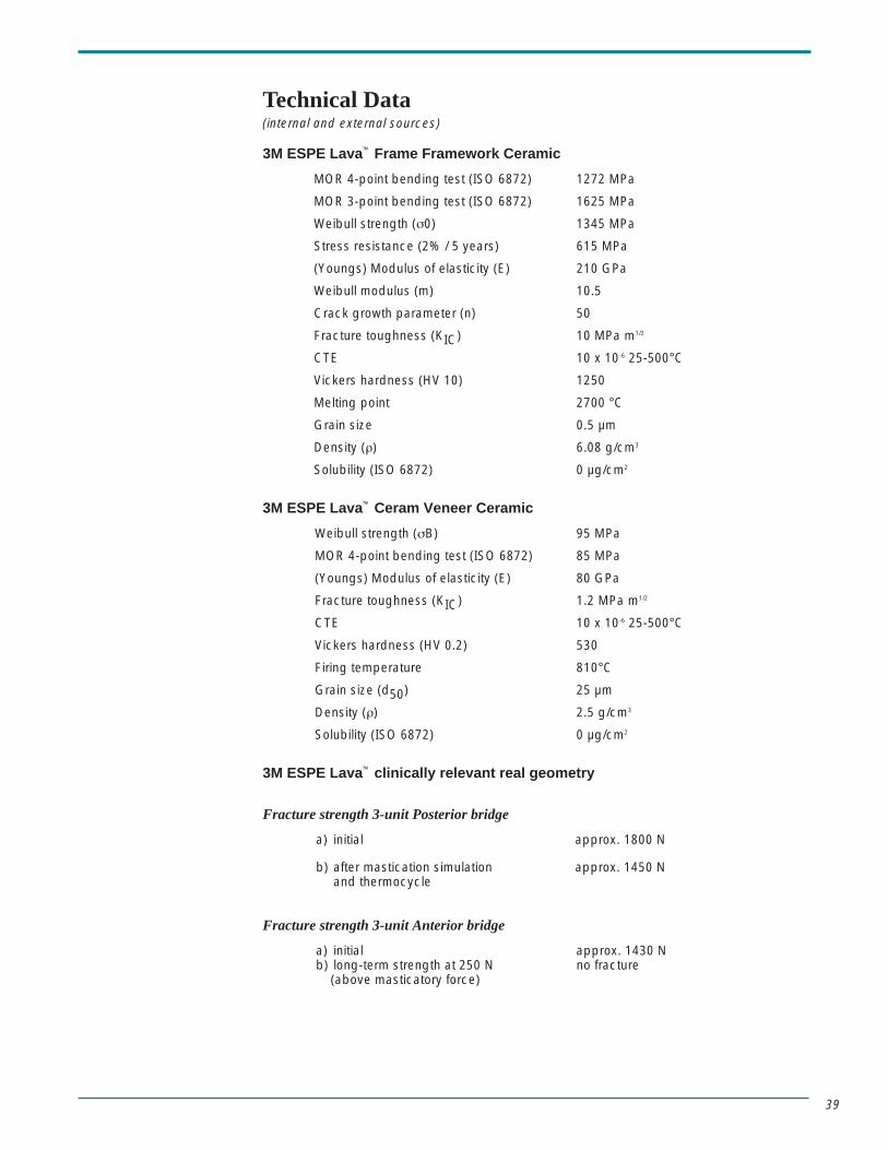
Technical Data(internal and external sources)
3M ESPE Lava™ Frame Framework Ceramic
MOR 4-point bending test (ISO 6872) 1272 MPa
MOR 3-point bending test (ISO 6872) 1625 MPa
Weibull strength (σ0) 1345 MPa
Stress resistance (2% / 5 years) 615 MPa
(Youngs) Modulus of elasticity (E) 210 GPa
Weibull modulus (m) 10.5
Crack growth parameter (n) 50
Fracture toughness (KIC) 10 MPa m1/2
CTE 10 x 10-6 25-500°C
Vickers hardness (HV 10) 1250
Melting point 2700 °C
Grain size 0.5 µm
Density (ρ) 6.08 g/cm3
Solubility (ISO 6872) 0 µg/cm2
3M ESPE Lava™ Ceram Veneer Ceramic
Weibull strength (σB) 95 MPa
MOR 4-point bending test (ISO 6872) 85 MPa
(Youngs) Modulus of elasticity (E) 80 GPa
Fracture toughness (KIC) 1.2 MPa m1/2
CTE 10 x 10-6 25-500°C
Vickers hardness (HV 0.2) 530
Firing temperature 810°C
Grain size (d50) 25 µm
Density (ρ) 2.5 g/cm3
Solubility (ISO 6872) 0 µg/cm2
3M ESPE Lava™ clinically relevant real geometry
Fracture strength 3-unit Posterior bridge
a) initial approx. 1800 N
b) after mastication simulation approx. 1450 Nand thermocycle
Fracture strength 3-unit Anterior bridge
a) initial approx. 1430 Nb) long-term strength at 250 N no fracture
(above masticatory force)
3M, ESPE, Cojet, Ketac, Lava, and Rocatec are trademarks of 3M ESPE or 3M ESPE AG.Celay, HiCeram, In-Ceram, Omega 900, Vita and Vitadur are registered trademarks of VITA-Zahnfabrik H. Rauter GmbH & Co KG, Bad Säckingen, Germany.Empress is a registered trademark of Ivoclar Vivadent.CEREC is a registered trademark of Sirona Dental Systems GmbH.Procera is a registered trademark of Nobel Biocare.Dicor is a registered trademark of Dentsply, InternationalCerapearl is a registered trademark of Kyocera Corporation.
3M Center, Building 275-2SE-03St. Paul, MN 55144-1000
Dental Products3M CanadaPost Office Box 5757London, Ontario, Canada N6A4T1
40% Pre-consumer waste paper10% Post-consumer waste paper
Printed in U.S.A.© 3M IPC 2002 70-2009-3472-0