LAUNCH ESCAPE - NASA the early launch phase. Pitch Control Motor ... a fixed position 11 seconds...
10
LAUNCH ESCAPE STU OS & FRANGIBLE LAUNCH ESCAPE MOTOR THRUST ALIGNMENT FITIING LAUNCH ESCAPE MOTO PITCH CONTROL MOTO TOWER JETTISON MOTOR CANARD ACTUATOR POWER SYSTEMS & INSTRUMENTATION WIRE HARNESS LAUNCH ESCAPE TOWER ELECTRICAL DISCONNECT FITIINGS P-186 BOOST PROTECTIVE COVER (APEX SECTION) Launch escape subsystem The launch escape subsystem will take the com- mand module containing the astronauts away from the launch vehicle in case of an emergency on the pad or shortly after launch. The subsystem carries the CM to a sufficient height and to the side, away from the launch vehicle, so that the earth landing subsystem can operate. The subsystem looks like a large rocket con- nected to the command module by a lattice-work tower. It is 33 feet long and weighs about 8,000 pounds. The maximum diameter of the launch escape assembly is four feet. The forward or rocket section of the subsystem is cylindrical and houses three solid-propellant rocket motors and a ballast compartment topped by a nose cone containing instruments. The tower is made of titanium tubes attached at the top to a structural skirt that covers the rocket exhaust nozzles and at the bottom to the command module by means of an explosive connection. A boost protective cover is attached to the tower and completely covers the command module. This cover protects the command module from the rocket exhaust and also from the heating generated by launch vehicle boost through the atmosphere. It remains attached to the tower and is carried away when the launch escape assembly is jettisoned. The subsystem is activated automatically by the emergency detection system in the first 100 seconds or manually by the astronauts at any time from the pad to jettison altitude. With the Saturn V, the subsystem is jettisoned at about 295,000 feet, or about 30 seconds after ignition of the second stage; with the Saturn I B, the subsystem is jettisoned at about 275,000 feet, about 20 sec- onds after second stage ignition. 137
Transcript of LAUNCH ESCAPE - NASA the early launch phase. Pitch Control Motor ... a fixed position 11 seconds...
LAUNCH ESCAPE
STU OS & FRANGIBLE
LAUNCH ESCAPE MOTOR
THRUST ALIGNMENT FITIING
LAUNCH ESCAPE MOTO
PITCH CONTROL MOTO
TOWER JETTISON MOTOR
CANARD
ACTUATOR
POWER SYSTEMS & INSTRUMENTATION WIRE HARNESS
LAUNCH ESCAPE TOWER
ELECTRICAL DISCONNECT FITIINGS
P-186 BOOST PROTECTIVE COVER (APEX SECTION)
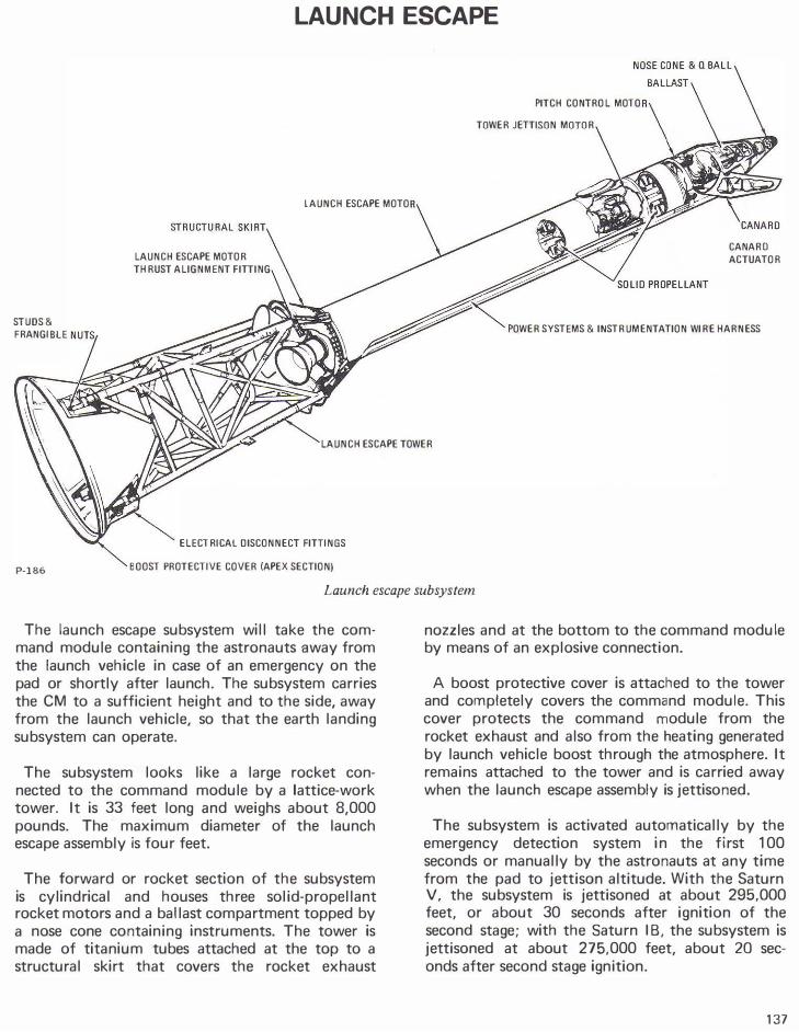
Launch escape subsystem
The launch escape subsystem will take the command module containing the astronauts away from the launch vehicle in case of an emergency on the pad or shortly after launch. The subsystem carries the CM to a sufficient height and to the side, away from the launch vehicle, so that the earth landing subsystem can operate.
The subsystem looks like a large rocket connected to the command module by a lattice-work tower. It is 33 feet long and weighs about 8,000 pounds. The maximum diameter of the launch escape assembly is four feet.
The forward or rocket section of the subsystem is cylindrical and houses three solid-propellant rocket motors and a ballast compartment topped by a nose cone containing instruments. The tower is made of titanium tubes attached at the top to a structural skirt that covers the rocket exhaust
nozzles and at the bottom to the command module by means of an explosive connection.
A boost protective cover is attached to the tower and completely covers the command module. This cover protects the command module from the rocket exhaust and also from the heating generated by launch vehicle boost through the atmosphere. It remains attached to the tower and is carried away when the launch escape assembly is jettisoned.
The subsystem is activated automatically by the emergency detection system in the first 100 seconds or manually by the astronauts at any time from the pad to jettison altitude. With the Saturn V, the subsystem is jettisoned at about 295,000 feet, or about 30 seconds after ignition of the second stage; with the Saturn I B, the subsystem is jettisoned at about 275,000 feet, about 20 seconds after second stage ignition.
137
100,000
w c :::> 1- 50 t= ...J <t: 1-a:: 0 al <t:
30
20
ABORTS
ABOVE
100,000 FT
DEPLOY CANARD
--42 � t>�-.'a �
.. � ··� TOWER JETTISON
VORIENTCM
AFT HEAT SHIELD
FORWARD .
DROGUES
PAD ABORTS
TOWER JETTISON
FORWARD HEAT
SHIELD JETTISON
QL-----------------------------------------��------------------------------------PAD
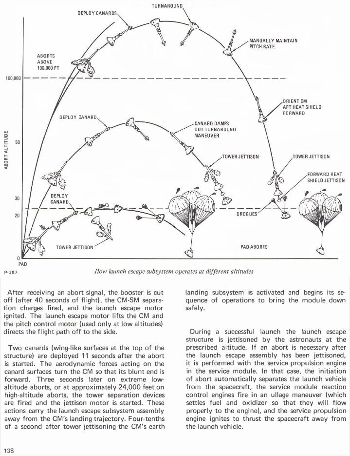
P-187 How launch escape subsystem operates at different altitudes
After receiving an abort signal, the booster is cut off (after 40 seconds of flight), the CM-SM separation charges fired, and the launch escape motor ignited. The launch escape motor lifts the CM and the pitch control motor (used only at low altitudes) directs the flight path off to the side.
Two canards (wing-like surfaces at the top of the structure) are deployed 11 seconds after the abort is started. The aerodynamic forces acting on the canard surfaces turn the CM so that its blunt end is forward. Three seconds later on extreme lowaltitude aborts, or at approximately 24,000 feet on high-altitude aborts, the tower separation devices are fired and the jettison motor is started. These actions carry the launch escape subsystem assembly away from the CM's landing trajectory. Four-tenths of a second after tower jettisoning the CM's earth
138
landing subsystem is activated and begins its sequence of operations to bring the module down safely.
During a successful launch the launch escape structure is jettisoned by the astronauts at the prescribed altitude. If an abort is necessary after the launch escape assembly has been jettisoned, it is performed with the service propulsion engine in the service module. In that case, the initiation of abort automatically separates the launch vehicle from the spacecraft, the service module reaction control engines fire in an ullage maneuver (which settles fuel and oxidizer so that they will flow properly to the engine), and the service propulsion engine ignites to thrust the spacecraft away from the launch vehicle.
The emergency detection system operates from the time of umbilical separation until 100 seconds after liftoff. It is designed to detect emergency conditions of the launch vehicle, display the information to the astronauts, and, if the system is on automatic, start an abort. Under certain conditions (excessive vehicle rates or two booster engines out), the system initiates an abort signal. This signal resets the event timer, activates the launch escape subsystem, and (after 30 to 40 seconds of flight) cuts off the launch vehicle engines. A "lockout" system prevents the emergency detection system from operating before liftoff.
A manual abort can be initiated before or during launch by the commander's translation control located on the arm of his couch. In an abort from the pad, the launch escape subsystem will carry the command module to a height of about 4,000 feet before it is jettisoned.
The nose cone of the launch escape assembly contains an instrument package called the 0-ball. The Q-ball has eight static ports (openings) through which pressure changes are measured. The instruments use this information to determine aerodynamic incidence angle and dynamic pressure data. The instruments send information on the angle of attack to an indicator of the CM's main display console and to the launch vehicle guidance.
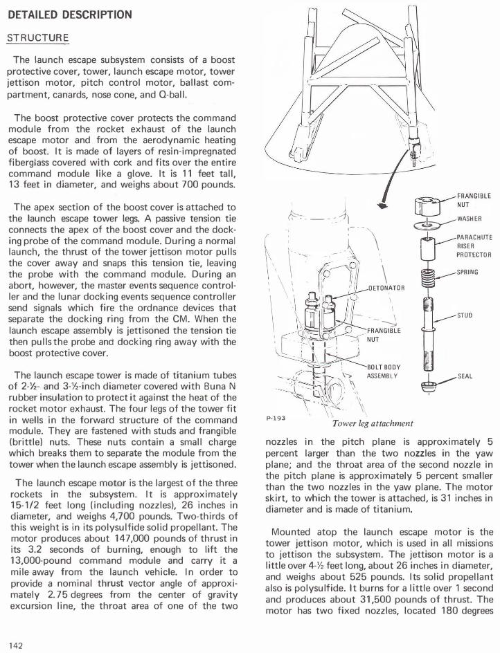
The canards are two deployable surfaces and operating mechanisms which are faired (attached in a smooth line) into the outer skin of the launch escape assembly just below the nose cone. The operating mechanism is inside the structure. Each canard is mounted on two hinges and is deployed by a gas-operated actuator. Eleven seconds after the abort signal is received by the master events sequence controller, an electric current fires cartridges to open the canards. Gas from the cartridges causes a piston to retract, operating the opening mechanism. The canard surfaces mechanically lock in place when fully opened.
The launch escape and pitch control motors are produced by Lockheed Propulsion Co., Redlands, Calif. The tower jettison motor is produced by Thiokol Chemical Corp., Elkton; Md.
EQUIPMENT
Launch Escape Motor (Lockheed Propulsion Co.) - Solid rocket motor about 15-1/2 feet long and 26 inches in diameter in steel case; P-188
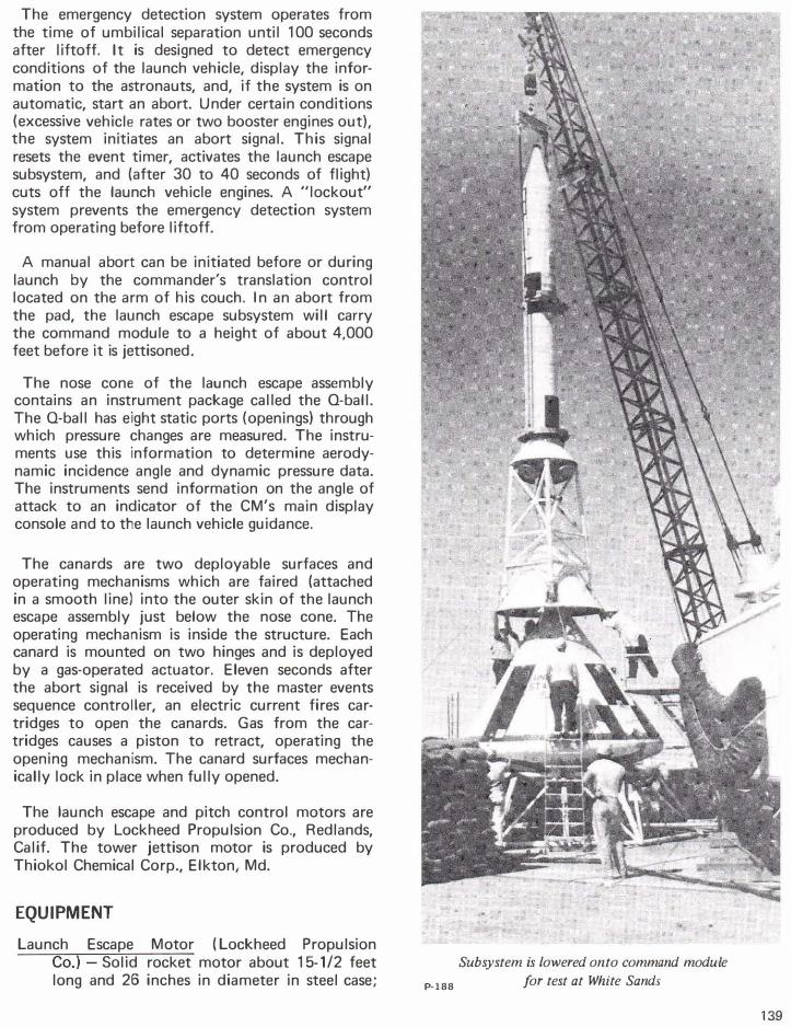
Subsystem is lowered onto command module
for test at White Sands
139
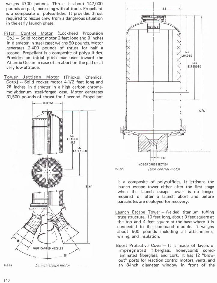
weighs 4700 pounds. Thrust is about 147,000 pounds on pad, increasing with altitude. Propellant is a composite of polysulfides. It provides thrust required to rescue crew from a dangerous situation in the early launch phase.
P i t c h Control Motor (Lockheed Propulsion Co.) - Solid rocket motor 2 feet long and 9 inches in diameter in steel case; weighs 50 pounds. Motor generates 2,400 pounds of thrust for half a second. Propellant is a composite of polysulfides. Provides an initial pitch maneuver toward the Atlantic Ocean in case of an abort on the pad or at very low altitude.
T o w e r Jettison M otor (Thiokol Chemical Corp.) -Solid rocket motor 4-1/2 feet long and 26 inches in diameter in a high carbon chromemolybdenum steel-forged case. Motor generates 31,500 pounds of thrust for 1 second. Propellant
P-189
140
CG LOADED
85.7
CG EXPENDED
dl
FOUR CANTED NOZZLES
35--l-- 35
Launch escape motor
P-190
t------+-- 8.8 -----�
12.3 LOADED
13.5 EXPENDED
1-it-----'--22.00
MOTOR CROSS SECTION
Pitch control motor
is a composite of polysulfides. It jettisons the launch escape tower either after the first stage when the launch escape tower is no longer required or after a launch abort and before parachutes are deployed for recovery.
Launch Escape Tower- Welded titanium tubing truss structure, 10 feet long, about 3 feet square at the top and 4 feet square at the base where it is connected to the command module. It weighs about 500 pounds including all attachments, wiring, and insulation.
Boost Protective Cover- It is made of layers of i m p r e g n a t e d f i berglass, honeycomb coredlaminated fiberglass, and cork. It has 12 "blowout" ports for reaction control motors, vents, and an 8-inch diameter window in front of the
-----25.750----
55.617
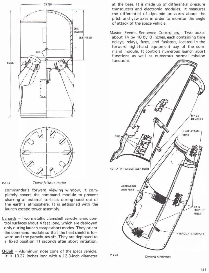
P-191 Tower jettison motor
20.8 LOADED
25.5 FIRED
commander's forward viewing window. It completely covers the command module to prevent charring of external surfaces during boost out of the earth's atmosphere. It is jettisoned with the launch escape tower assembly.
Canards- Two metallic clamshell aerodynamic control surfaces about 4 feet long, which are deployed only during launch escape abort modes. They orient the command module so that the heat shield is forward and the parachutes aft. They are deployed to a fixed position 11 seconds after abort initiation.
Q-Ball -Aluminum nose cone of the space vehicle. ---;tiS 13.37 inches long with a 13.3-inch diameter
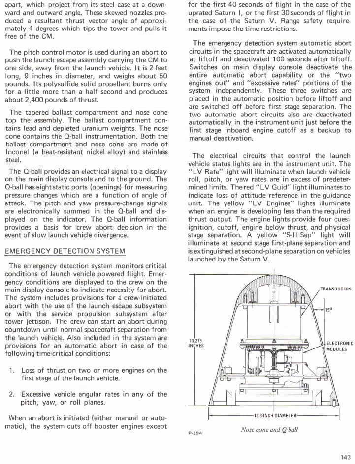
at the base. It is made up of differential pressure transducers and electronic modules. It measures the differential of dynamic pressures about the pitch and yaw axes in order to monitor the angle of attack of the space vehicle.
Master Events Sequence Controllers-Two boxes about 14 by 10 by 8 inches, each containing time delays, relays, fuses, and fusistors, located in the forward right-hand equipment bay of the command module. It controls numerous launch abort functions as well as numerous normal mission functions.
ARM PORT
RINGS
HINGE ATTACH POINT
P-192 Canard structure
141
DETAILED DESCRIPTION
STRUCTURE
The launch escape subsystem consists of a boost protective cover, tower, launch escape motor, tower jettison motor, pitch control motor, ballast compartment, canards, nose cone, and Q-ball.
The boost protective cover protects the command module from the rocket exhaust of the launch escape motor and from the aerodynamic heating of boost. It is made of layers of resin-impregnated fiberglass covered with cork and fits over the entire command module like a glove. It is 11 feet tall, 13 feet in diameter, and weighs about 700 pounds.
The apex section of the boost cover is attached to the launch escape tower legs. A passive tension tie connects the apex of the boost cover and the docking probe of the command module. During a normal launch, the thrust of the tower jettison motor pulls the cover away and snaps this tension tie, leaving the probe with the command module. During an abort, however, the master events sequence controller and the lunar docking events sequence controller send signals which fire the ordnance devices that separate the docking ring from the CM. When the launch escape assembly is jettisoned the tension tie then pulls the probe and docking ring away with the boost protective cover.
The launch escape tower is made of titanium tubes of 2-Y2- and 3-Y2-inch diameter covered with Buna N rubber insulation to protect it against the heat of the rocket motor exhaust. The four legs of the tower fit in wells in the forward structure of the command module. They are fastened with studs and frangible (brittle) nuts. These nuts contain a small charge which breaks them to separate the module from the tower when the launch escape assembly is jettisoned.
The launch escape motor is the largest of the three rockets in the subsystem. It is approximately 15-1/2 feet long (including nozzles), 26 inches in diameter, and weighs 4,700 pounds. Two-thirds of this weight is in its polysulfide solid propellant. The motor produces about 147,000 pounds of thrust in its 3.2 seconds of burning, enough to lift the 13,000-pound command module and carry it a mile away from the launch vehicle. In order to provide a nominal thrust vector angle of approximately 2. 75 degrees from the center of gravity excursion line, the throat area of one of the two
142
�----� ; :-·-\ �FRANGIBLE lj_j NUT
�WASHER
( \" -· \ I I'-- - !:Pr�11 \ 11 \ 11 • I( ,•'II. OETONfTOR \ \ �1 1� I . ' 9J1- --�
.-\��� ��FRANGIBLE I c ,�,�� NUT I -:- � I I " -�� �----BOLTBOOY r.-:--l .J ' ....... ��- Fr- \"-;> ASSEMBLY
��r�,� � � �,\�, \ P-193 Tower leg attachment
I PARACHUTE RISER PROTECTOR
SPRING
STUO
�
SEAL
I
nozzles in the pitch plane is approximately 5 percent larger than the two nozzles in the yaw plane; and the throat area of the second nozzle in the pitch plane is approximately 5 percent smaller than the two nozzles in the yaw plane. The motor skirt, to which the tower is attached, is 31 inches in diameter and is made of titanium.
Mounted atop the launch escape motor is the tower jettison motor, which is used in all missions to jettison the subsystem. The jettison motor is a little over 4-Y2 feet long, about 26 inches in diameter, and weighs about 525 pounds. Its solid propellant also is polysulfide. It burns for a little over 1 second and produces about 31,500 pounds of thrust. The motor has two fixed nozzles, located 180 degrees
apart, which project from its steel case at a downward and outward angle. These skewed nozzles produced a resultant thrust vector angle of approximately 4 degrees which tips the tower and pulls it free of the CM.
The pitch control motor is used during an abort to push the launch esGape assembly carrying the CM to one side, away from the launch vehicle. It is 2 feet long, 9 inches in diameter, and weighs about 50 pounds. Its polysulfide solid propellant burns only for a little more than a half second and produces about 2,400 pounds of thrust.
The tapered ballast compartment and nose cone top the assembly. The ballast compartment contains lead and depleted uranium weights. The nose cone contains the 0-ball instrumentation. Both the ballast compartment and nose cone are made of lnconel (a heat-resistant nickel alloy) and stainless steel.
The 0-ball provides an electrical signal to a display on the main display console and to the ground. The 0-ball has eight static ports (openings) for measuring pressure changes which are a function of angle of attack. The pitch and yaw pressure-change signals are electronically summed in the 0-ball and displayed on the indicator. The 0-ball information provides a basis for crew abort decision in the event of slow launch vehicle divergence.
EMERGENCY DETECTION SYSTEM
The emergency detection system monitors critical conditions of launch vehicle powered flight. Emergency conditions are displayed to the crew on the main display console to indicate necessity for abort. The system includes provisions for a crew-initiated abort with the use of the launch escape subsystem or with the service propulsion subsystem after tower jettison. The crew can start an abort during countdown until normal spacecraft separation from the launch vehicle. Also included in the system are provisions for an automatic abort in case of the following time-critical conditions:
1. Loss of thrust on two or more engines on the first stage of the launch vehicle.
2. Excessive vehicle angular rates in any of the pitch, yaw, or roll planes.
When an abort is initiated (either manual or automatic), the system cuts off booster engines except
for the first 40 seconds of flight in the case of the uprated Saturn I, or the first 30 seconds of flight in the case of the Saturn V. Range safety requirements impose the time restrictions.
The emergency detection system automatic abort circuits in the spacecraft are activated automatically at I iftoff and deactivated 1 00 seconds after liftoff. Switches on main display console deactivate the entire automatic abort capability or the "two engines out" and "excessive rates" portions of the system independently. These three switches are placed in the automatic position before liftoff and are switched off before first stage separation. The two automatic abort circuits also are deactivated automatically in the instrument unit just before the first stage inboard engine cutoff as a backup to manual deactivation.
The electrical circuits that control the launch vehicle status lights are in the instrument unit. The "LV Rate" light will illuminate when launch vehicle roll, pitch, or yaw rates are in excess of predetermined limits. The red "LV Guid" light illuminates to indicate loss of attitude reference in the guidance unit. The yellow "LV Engines" lights illuminate when an engine is developing less than the required thrust output. The engine lights provide four cues: ignition, cutoff, engine below thrust, and physical stage separation. A yellow "S-11 Sep" I ight wi II illuminate at second stage first-plane separation and is extinguished at second-plane separation on vehicles launched by the Saturn V.
13.275 INCHES
P·l94
1------lJ.J.INCH DIAMETER------I
Nose cone and Q-ball
143
The "Abort" light is a red lamp assembly containing four bulbs that provide high-intensity illumination. This light is illuminated if an abort is requested by the launch control center for a pad abort or an abort during liftoff via up-data link. The "Abort" light also can be illuminated after liftoff by the range safety officer, or via the up-data link from the manned spacecraft flight network.
The emergency detection system will automatically initiate an abort signal when two or more first stage engines are out or when launch vehicle excessive rates are sensed by gyros in the instrument unit. The abort signals are sent to the master events sequence controller, which initiates the abort procedure.
LAUNCH ESCAPE TOWER JETTISON
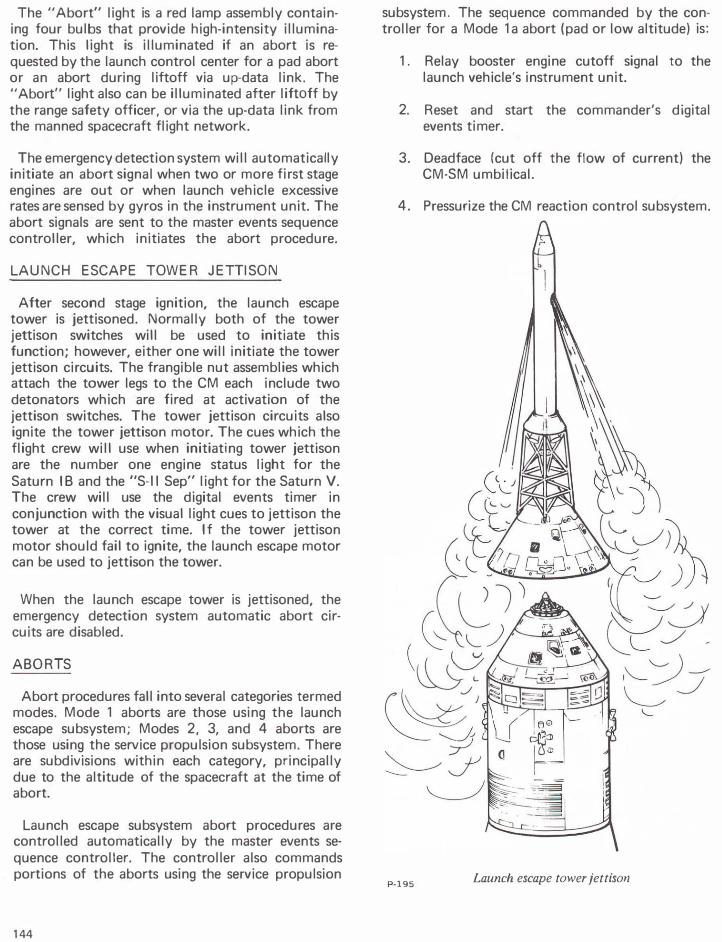
After second stage ignition, the launch escape tower is jettisoned. Normally both of the tower jettison switches will be used to initiate this function; however, either one will initiate the tower jettison circuits. The frangible nut assemblies which attach the tower legs to the CM each include two detonators which are fired at activation of the jettison switches. The tower jettison circuits also ignite the tower jettison motor. The cues which the flight crew will use when initiating tower jettison are the number one engine status light for the Saturn I B and the "S-11 Sep" light for the Saturn V. The crew will use the digital events timer in conjunction with the visual light cues to jettison the tower at the correct time. If the tower jettison motor should fail to ignite, the launch escape motor can be used to jettison the tower.
When the launch escape tower is jettisoned, the emergency detection system automatic abort circuits are disabled.
ABORTS
Abort procedures fall into several categories termed modes. Mode 1 aborts are those using the launch escape subsystem; Modes 2, 3, and 4 aborts are those using the service propulsion subsystem. There are subdivisions within each category, principally due to the altitude of the spacecraft at the time of abort.
Launch escape subsystem abort procedures are controlled automatically by the master events sequence controller. The controller also commands portions of the aborts using the service propulsion
144
subsystem. The sequence commanded by the controller for a Mode 1 a abort (pad or low altitude) is:
1. Relay booster engine cutoff signal to the launch vehicle's instrument unit.
2. Reset and start the commander's digital events timer.
3. Deadface (cut off the flow of current) the CM-SM umbilical.
4. Pressurize the CM reaction control subsystem.
P-195 Launch escape tower jettison
5. Transfer electrical control from the SM reaction control engines to the CM reaction control engines.
6. Transfer entry and post-landing battery power to the main de bus tie.
7. Fire ordnance devices to cut CM-SM tension and ties and to activate the CM-SM umbilical guillotine.
8. Ignite the launch escape and pitch control motors.
9. Start rapid CM reaction control subsystem propellant dumping and purging.
10. Deploy launch escape subsystem canards.
11. Activate the earth landing subsystem controller.
12. Jettison the launch escape tower.
13. Fire charges to separate the docking ring.
14. Jettison the forward heat shield.
15. Fire the mortar to deploy the heat shield drag parachute.
16. Deploy the drogue parachutes.
17. Purge CM reaction control subsystem.
18. Release the drogue parachutes.
19. Deploy the pilot parachutes (which pull out the main parachutes).
20. Deploy the two VHF recovery antennas and the flashing beacon light.
21. After splashdown, release the main parachutes.
The sequence differs slightly for other aborts using the launch escape subsystem. On high-altitude aborts, for example, the pitch control motor is not fired, dumping of the CM reaction control propellant follows the normal entry procedure (during descent on the main parachutes), and the reaction jet engine control is not cut off (enabling the stabilization and control subsystem to control the CM's attitude automatically).
TOWER JETIISON �CE 295,000 FT -r-1--- .y �����LSION
MOOElC
100.000 FT
T + 42 SEC
PAD
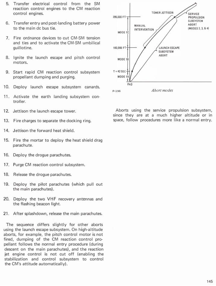
P-196
SUBSYSTEM
MANUAL ABORT
(MODES 2. 3. & 4)
ABORT
Abort modes
Aborts using the service propulsion subsystem, since they are at a much higher altitude or in space, follow procedures more like a normal entry.
145
,
n
.1::'
•
•
P-197
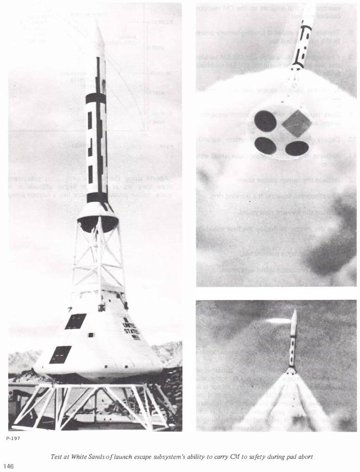
Test at White Sands of launch escape subsystem's ability to carry CM to safety during pad abort
146