LaserCut61 Manual V1.1
60
LaserCut61 Laser Engraving & Cutting Control System Manual V1.1 May, 2014
Transcript of LaserCut61 Manual V1.1

LaserCut61Laser Engraving & Cutting Control System
Manual
V1.1
May, 2014

Laser Engraving & Cutting Control System Manual
2
Content
1 System Installation--------------------------------------------------------------------------------------------3
2 Quick Guide
2.1 Main Interface of the Software--------------------------------------------------------------------4
2.2 Import Data-------------------------------------------------------------------------------------------5
2.3 Set Process Parameter-------------------------------------------------------------------------------6
2.4 Download File----------------------------------------------------------------------------------------7
2.5 Process------------------------------------------------------------------------------------------------7
3 Detail of Software Operation
3.1 Import and Save Data-------------------------------------------------------------------------------8
3.2 Drawing Tools---------------------------------------------------------------------------------------8
3.3 Edit---------------------------------------------------------------------------------------------------10
3.4 Technical Process----------------------------------------------------------------------------------18
3.5 Set Process Parameter-----------------------------------------------------------------------------24
3.6 Output-----------------------------------------------------------------------------------------------31
3.7 Machine CFG--------------------------------------------------------------------------------------33
3.8 Machine Check------------------------------------------------------------------------------------41
4 Control Panel
4.1 Overview of Control Panel-----------------------------------------------------------------------43
4.2 Start Interface--------------------------------------------------------------------------------------44
4.3 Main Interface-------------------------------------------------------------------------------------44
4.4 Processing Interface-------------------------------------------------------------------------------45
4.5 Supporting Interface-------------------------------------------------------------------------------48
4.6 Error Alarm Interface------------------------------------------------------------------------------51
5 Appendix
5.1 IP Set-----------------------------------------------------------------------------------------------53
5.2 How to control several machine in one LaserCut---------------------------------------------53
5.3 Quick Operation----------------------------------------------------------------------------------54
5.4 Description of Auto Separation 2-Head Machine--------------------------------------------55
5.5 Make AI File--------------------------------------------------------------------------------------58
5.6 Backlash Adjustment of Engraving------------------------------------------------------------59
5.7 FQA------------------------------------------------------------------------------------------------60
Laser Engraving & Cutting Control System Manual
3
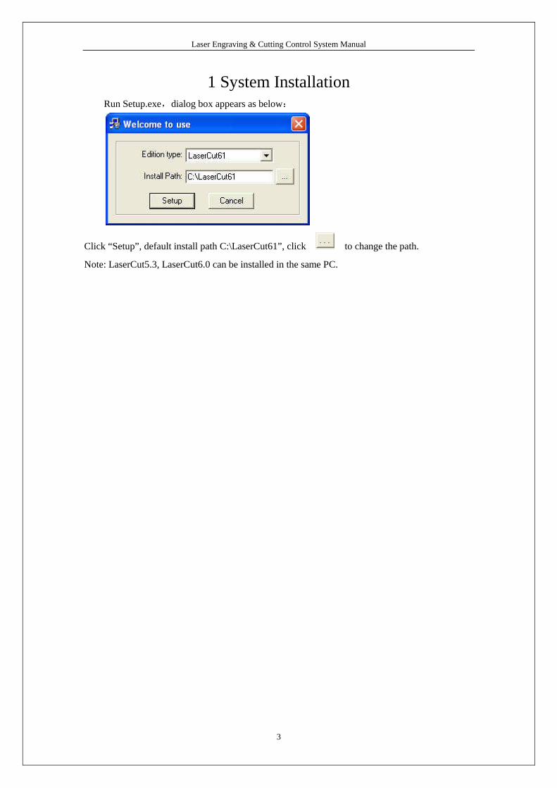
1 System InstallationRun Setup.exe,dialog box appears as below:
Click “Setup”, default install path C:\LaserCut61”, click to change the path.
Note: LaserCut5.3, LaserCut6.0 can be installed in the same PC.

Laser Engraving & Cutting Control System Manual
4
2 Quick Guide
2.1 Main Interface of the Software
Run the software, main interface appears as below:
Functions can be shown after a short delay of the mouse on the button.
Import Data
Simulate
Control panelSet Technics CFG
Edit Toolbar
LayerStatus bar
Save Data Set Stop Position

Laser Engraving & Cutting Control System Manual
5
2.2 Import Data
The button that the cursor indicates is “Import”.
You can import files that the system supports.

Laser Engraving & Cutting Control System Manual
6
2.3 Set Processing Parameter
Select processing mode in the pull-down menu.
Double click and enter the processing parameter setting interface.
Input proper parameter (i.e. speed, power).

Laser Engraving & Cutting Control System Manual
7
2.4 File Download
When first time operates the system, you should click “Download CFG”.
You can name the file when download.
2.5 Process
Click “Start”in the main interface and the file will be processed;
Click “Start”on the control panel can also start the processing.
When processing finished, the control panel will alarm.

Laser Engraving & Cutting Control System Manual
8
3 Detail of Software Operation
3.1 Import and Save Data
3.1.1 New
Click to create a new processing file.
3.1.2 Import
Click to import software support file format, such as *.PLT、*.AI、*.DXF、*.DST、
*.BMP、NC code etc.
3.1.3 Save
Click to save the current editing graph as a processing file (*.ftp).
3.1.4 Open
Click to import a processing file (*.ftp)
3.1.5 Output
Save the current editing vector as a PLT or DXF file.
3.2 Drawing Tools
3.2.1 Line
Click on the left side toolbar to draw a line. After clicking the button, dragging the
mouse on the screen will draw a line as will. Press “Ctrl”at the same time as you drag the mouse
will draw a horizontal/vertical line.
3.2.2 Rectangle
Click on the left side toolbar to draw a rectangle. After clicking the button, dragging the
mouse on the screen will draw a rectangle with any size. Press “Ctrl”at the same time as you drag
the mouse will draw a square.
3.2.3 Ellipse
Click on the left side toolbar to draw an ellipse. After clicking the button, dragging the
mouse on the screen will draw an ellipse. Press “Ctrl”at the same time as you drag the mouse will
draw a circle.

Laser Engraving & Cutting Control System Manual
9
3.2.4 Bezier Curve
Click on the left side toolbar to draw a Bezier Curve. After clicking the button,
dragging the mouse on the screen will draw a Bezier Curve.
3.2.5 Text
Click on the left side toolbar and drag the mouse on the screen, dialog box appears as
below:
Text can’t be processed, and it have to be converted to curve (Drawing— convert to curve).
You can also set “Auto Convert Text to Curve”in Machine CFG.

Laser Engraving & Cutting Control System Manual
10
3.3 Edit
3.3.1 Rotate
Click the select button first to select the graph need to be rotated, and then click
“Rotate”button on the left side toolbar to rotate the graph. Dialog box appears as below:
Precise rotate angle can be made by inputting relevant numbers and click “OK”.
Click “Cancel”and any rotation can be made by dragging the mouse as it shows below:
3.3.2 Mirror
Click the select button first to select the graph need to be mirrored, and then click
“Vertical Mirror”button on the left side toolbar to vertically mirroring the graph.
Click the select button first to select the graph need to be mirrored, and then click the
“Horizontal Mirror”button on the left side toolbar to horizontally mirroring the graph.
3.3.3 Node Edit
Click the button on the left side toolbar to edit the node of the vector graph selected.
Click the button and nods on the vector graph selected will be shown in the form of small box. It
appears as below:
Laser Engraving & Cutting Control System Manual
11
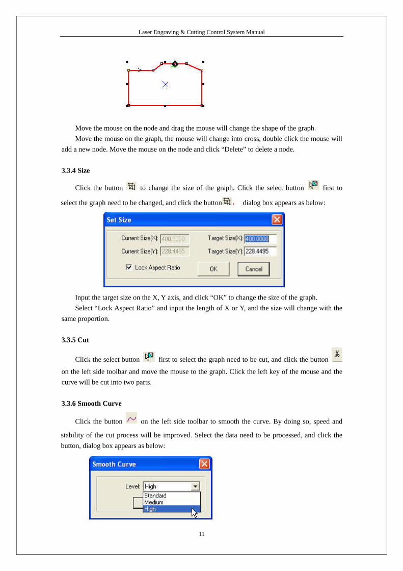
Move the mouse on the node and drag the mouse will change the shape of the graph.
Move the mouse on the graph, the mouse will change into cross, double click the mouse will
add a new node. Move the mouse on the node and click “Delete”to delete a node.
3.3.4 Size
Click the button to change the size of the graph. Click the select button first to
select the graph need to be changed, and click the button , dialog box appears as below:
Input the target size on the X, Y axis, and click “OK”to change the size of the graph.
Select “Lock Aspect Ratio”and input the length of X or Y, and the size will change with the
same proportion.
3.3.5 Cut
Click the select button first to select the graph need to be cut, and click the button
on the left side toolbar and move the mouse to the graph. Click the left key of the mouse and the
curve will be cut into two parts.
3.3.6 Smooth Curve
Click the button on the left side toolbar to smooth the curve. By doing so, speed and
stability of the cut process will be improved. Select the data need to be processed, and click the
button, dialog box appears as below:

Laser Engraving & Cutting Control System Manual
12
There are three levels: standard, medium and high. The graph will be bigger after smoothed.
3.3.7 Generate parallel lines
This is used to expand or reduce the vector graph. Click the select button first to select
the graph need to be processed, and then click the button on the left side toolbar, dialog box
appears as below:
Select the needed option to generate parallel lines on a new layer. As it shows below:
Corner type can be selected as circle or sharp. Select circle, the lines will be smoother, but
small distortion will be in the corner.
Combine: It is only used when “Double Outer”is selected. A sample shows as below:
The left side is the result when “Double Outer”and “Connect”are selected.
3.3.8 Invert color of Bitmap
Click the button on the left side toolbar to invert the color of the BMP image. The

Laser Engraving & Cutting Control System Manual
13
process result will be intaglio or anaglyph. It appears as below:
3.3.9 Array
Array Copy: Click the select button first to select the graph need, and then click the
button on the left side toolbar, dialog box appears as below:
Input relevant parameters, identical graph with the number of the “lines × columns”will
appear on the screen. The space between graphs will be determined by the “Space”.
Virtual Array: Click the button on the left side toolbar, dialog box appears as below:
Cell width (X): original size of the graphics.
Cell height (Y): original size of the graphics.
Number: lines or columns needed for the output data.
Space: space between lines or columns.
Width: width of the whole data after virtual arraying.
Height: height of the whole data after virtual arraying.
Space Along Y: space of the dislocation between adjacent columns.
Space Along X: space of the dislocation between adjacent rows.

Laser Engraving & Cutting Control System Manual
14
Absolute Space Mode: if the space is 0, select “Absolute Space Mode”, and the graph will
be overlapped completely.
Y First: the cut route will along Y direction.
Auto-cover Calculation: Click the button, and dialog box appears as below:
Material Width: width of the materials to process (default as the width of the worktable).
Material Height: length of the materials to process (default as the length of the worktable).
The rows and columns needed to cover the material will be calculated automatically
according to the parameters input.
A sample shows as below:
Part Virtual Array
If graph is made up of many graph entity, an entity of the graph can be virtual arrayed. Select
the unit and click on the left side toolbar, and dialog box appears as below:

Laser Engraving & Cutting Control System Manual
15
3.3.10 Group and Ungroup
Select the graph entity need to be grouped, click the group button , and the graph entity
will be grouped.
Select the grouped graph, and then click the ungroup button , and the graph will be
disassembled to several graph entity.
3.3.11 Layer Property
Corresponding icon is on the grounded toolbar.
Visible: the layer is visible or not.
Laser Engraving & Cutting Control System Manual
16
Lock: when a layer is locked, it cannot be edited.
TechnicsPt: the technique ports are shown or not.
3.3.12 Align
Corresponding icon is on the grounded toolbar.
3.3.13 Quick move data
Corresponding icon is on the grounded toolbar.
Move the selected data to corners of the drawing area.
3.3.14 Connect End to End lines
Location: Tool Connect End to End.
Connect the several lines linked end to end into one. Select lines need to be processed, and
click the button will do.
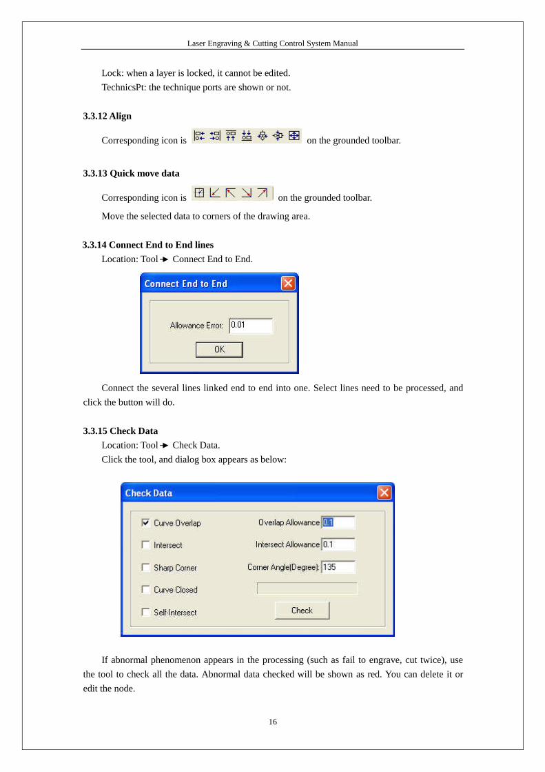
3.3.15 Check Data
Location: Tool Check Data.
Click the tool, and dialog box appears as below:
If abnormal phenomenon appears in the processing (such as fail to engrave, cut twice), use
the tool to check all the data. Abnormal data checked will be shown as red. You can delete it or
edit the node.
Laser Engraving & Cutting Control System Manual
17
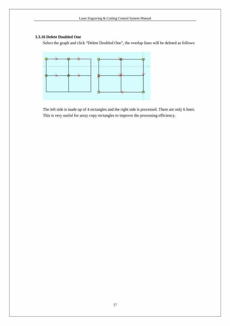
3.3.16 Delete Doubled One
Select the graph and click “Delete Doubled One”, the overlap lines will be deleted as follows:
The left side is made up of 4 rectangles and the right side is processed. There are only 6 lines.
This is very useful for array copy rectangles to improve the processing efficiency.
Laser Engraving & Cutting Control System Manual
18
3.4 Technics Process
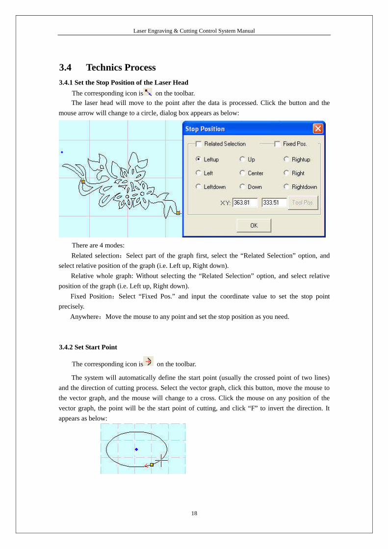
3.4.1 Set the Stop Position of the Laser Head
The corresponding icon is on the toolbar.
The laser head will move to the point after the data is processed. Click the button and the
mouse arrow will change to a circle, dialog box appears as below:
There are 4 modes:
Related selection:Select part of the graph first, select the “Related Selection”option, and
select relative position of the graph (i.e. Left up, Right down).
Relative whole graph: Without selecting the “Related Selection”option, and select relative
position of the graph (i.e. Left up, Right down).
Fixed Position:Select “Fixed Pos.” and input the coordinate value to set the stop point
precisely.
Anywhere:Move the mouse to any point and set the stop position as you need.
3.4.2 Set Start Point
The corresponding icon is on the toolbar.
The system will automatically define the start point (usually the crossed point of two lines)
and the direction of cutting process. Select the vector graph, click this button, move the mouse to
the vector graph, and the mouse will change to a cross. Click the mouse on any position of the
vector graph, the point will be the start point of cutting, and click “F”to invert the direction. It
appears as below:

Laser Engraving & Cutting Control System Manual
19
3.4.3 Set lead-in/out line
Location: Tool Set lead-in/out line.
Lead Pos: set the situation of adding lead line.
Lead Dir: set the cutting direction (clockwise or counter-clockwise).
Lead in/out Setting: set the shape and size of lead in/out lines.
Cut Mode: choose “Female Cut”or “Male Cut”in the drop-down list to define whether the
lead-in/out line is in the outline of the figure or not.
Overlap: defines the sealing distance of the process vector graph.
Apply to: set the overlap apply to all the graph, outer boundary or inner boundary.
Gap Offset: set the compensation parameters.
: set the same parameter for the lead out line as those of the lead in line.

Laser Engraving & Cutting Control System Manual
20
3.4.4 Set Output Sequence
Auto set:
Location: Tool Auto sort
There are 9 rectangles as above, select different parameter and the cutting sequence as
follows.
The sequence is: 1→ 2→ 3→ 4→ 5→ 6→ 7→ 8→ 9.

Laser Engraving & Cutting Control System Manual
21
The sequence is: 1→ 4→ 7→ 2→ 5→ 8→ 3→ 6→ 9.
The sequence is: 1→ 2→ 3→ 6→ 5→ 4→ 7→ 8→ 9.
The sequence is: 1→ 4→ 7→ 8→ 5→ 2→ 3→ 6→ 9.

Laser Engraving & Cutting Control System Manual
22
Sample of “Divide Height” (There are 6 sections (20mm*20m), and each includes 8
triangles).
Divide height value 25 means the whole graph is divided into 6 sections (25mm*25mm). The
6 area run sequence 1→ 2→ 3→ 4→ 5→ 6.
Start Pos:
This is the start position of the cutting route. There are 4 options: Left Bottom, Right Bottom,
Left Up, and Right Up.
Auto Set Start Point:
Check this option and the system will adjust the start point to get shortest path.
Backlash Optimize:
Check this option and the system will automatically define cut direction to compensate the
backlash in cutting. But it will increase the idle movement. Generally, this option won’t be
checked.

Laser Engraving & Cutting Control System Manual
23
Manual Sort:
Location: Tool Manual Sort
As above, the graph is made up of 3 entities: a circle (28), a rectangle (29) and a triangle (30).
Default sequence is circle (28), rectangle (29) and triangle (30).
Click 2 in graph list,and select the triangle , click “Add(S)”, the sequence will change to:
circle (28), triangle (30), and rectangle (29).
Add(S): add the selected entity to graph list.
Top: add the selected entity to the head.
Bottom: add the selected entity to the end.
1 Entity Only: select this option, and only one entity can be selected.
Auto Sort: select this option and the system will set the sequence according to the parameters

Laser Engraving & Cutting Control System Manual
24
in “Para”.
If there are many layers, “Up”and “Down”can change the sequence of the layers.
Graph can be re-selected, and the re-selected part will be arranged at the first time that it be
selected.
Knife mold sort:
When check “Knife mold”as the auto sort mode in Machine CFG, the “auto set”interface will
be shown as bellow.
Bridge Length: it is determined when drawing the file. Input the value is OK.
3.4.5 Divide Layer
Layer toolbar:
If the graph has many colors, system will divide it to many layers automatically.
If the graph has only one color, select some figures and click a color on the layer toolbar, and
the system will divide the graph to many layers as wants.
3.5 Set Processing Parameters
3.5.1 Layer Management
Process sequence is from the top to the bottom of the layer list. Select one line in the list and
click or , and the process sequence will be changed.
Process mode can be selected in the drop-down list of the “Mode”column. It shows as
below:

Laser Engraving & Cutting Control System Manual
25
Output the layer or not can be set in the “Output”column. is output and
is not.
Double click one line in the list and set processing parameters.
3.5.2 Set Cut Parameters
Work Speed: cutting speed of the laser head in cutting.
Work Acceleration: the acceleration of the movement on the X, Y-Axis.
Corner Acceleration: when laser head moves to the corner of the curve, it has to decrease
the speed. If the value is too large, the machine will shake intensively when the laser head moves
into the corner and create saw tooth. If it is too small, the process efficiency will be decreased. It is
generally 2 times of the acceleration.
Power1/2: adjust the laser power (unit: %).

Laser Engraving & Cutting Control System Manual
26
Corner Power1/2: adjust power of laser head when the speed is the minimum in the variable
speed motion.
(Adjustment of the power and corner power can ensure an unchanged strength of the laser in
the process).
Overlap Length: closed graph may not to be cut down due to the mechanical error. This
parameter helps to solve the problem, but it should not be too large. It is suggest to adjust
mechanical assemble precision to solve the problem.
Blow mode:
Not Blow: not to blow in the process.
Cut Blow: blow when laser on, stop blowing when laser off. This function needs hardware
support.
Always blow: blow at the moment laser head begins to move, and close at the end of the
process. This function needs hardware support.
Flying Cut: select this option and the system will cut with fast mode.
Flying Cut Mode:
Dotted Line: cut the line to dotted line. 1,-1 descript the dotted line.
Jump for Fast: this mode can increase cutting efficiency and quality, but it is only useful when
the graph processed by “Part Virtual Array”.
Layer Times: a layer can be processed many times. Input the value as you need.
Delay before laser on: set the delay before the laser is on
Laser Engraving & Cutting Control System Manual
27
Delay after laser on: set the delay after the laser is on.
Delay before laser off: set the delay before the laser is off.
Delay after laser off: set the delay after the laser is off.
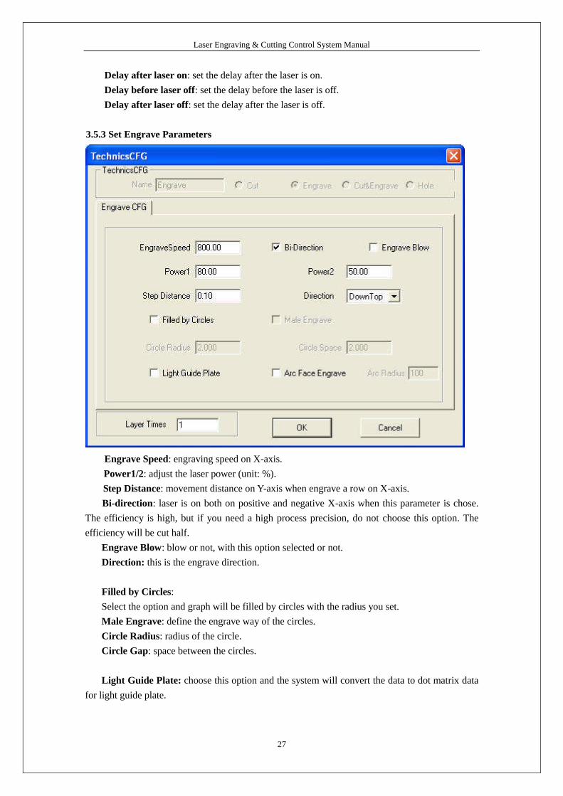
3.5.3 Set Engrave Parameters
Engrave Speed: engraving speed on X-axis.
Power1/2: adjust the laser power (unit: %).
Step Distance: movement distance on Y-axis when engrave a row on X-axis.
Bi-direction: laser is on both on positive and negative X-axis when this parameter is chose.
The efficiency is high, but if you need a high process precision, do not choose this option. The
efficiency will be cut half.
Engrave Blow: blow or not, with this option selected or not.
Direction: this is the engrave direction.
Filled by Circles:
Select the option and graph will be filled by circles with the radius you set.
Male Engrave: define the engrave way of the circles.
Circle Radius: radius of the circle.
Circle Gap: space between the circles.
Light Guide Plate: choose this option and the system will convert the data to dot matrix data
for light guide plate.

Laser Engraving & Cutting Control System Manual
28
Layer Times: a layer can be processed many times. Input the value as you need.
3.5.4 Set Cut and Engrave Parameters
Please refer to 3.5.2 and 3.5.3.
Engrave and cut mode means when process a graph, engrave first and then cut.
3.5.5 Set Hole Parameters
Hole Span Length: distance between two adjacent holes.
Power1/2: adjust the laser power (unit: %).
Hole Delay: delay time of the laser head in punching a hole (unit: second).
Blow: blow or not, with this parameter chose or not.
Hole on Center: punch a hole on the center of each closed vector graph.
Layer Times: a layer can be processed many times. Input the value as you need.
Laser Engraving & Cutting Control System Manual
29
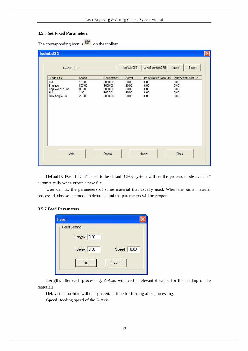
3.5.6 Set Fixed Parameters
The corresponding icon is on the toolbar.
Default CFG: If “Cut”is set to be default CFG, system will set the process mode as “Cut”
automatically when create a new file.
User can fix the parameters of some material that usually used. When the same material
processed, choose the mode in drop-list and the parameters will be proper.
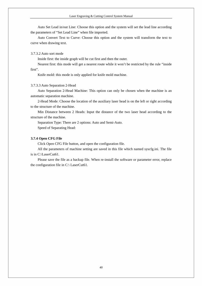
3.5.7 Feed Parameters
Length: after each processing, Z-Axis will feed a relevant distance for the feeding of the
materials.
Delay: the machine will delay a certain time for feeding after processing.
Speed: feeding speed of the Z-Axis.

Laser Engraving & Cutting Control System Manual
30
3.5.8 Auto 2-Head
If the machine has automatic separation function, select this option and the space between the
two laser head will adjust automatically; or the space between the two laser head won’t adjust and
the machine will be used as simple double laser head machine.
3.5.9 Immediately Output
System will process the data according to their coordinate in the worktable range when the
option not selected.
System will process the data from where the laser head is when the option selected. Relevant
relations between the stop position and the processing data remain unchanged.
3.5.10 Selected Output
When select the option, system will only process the graph selected.

Laser Engraving & Cutting Control System Manual
31
3.6 Output
3.6.1 Download File
Click “Download”button, dialog box appears as below:
Download CFG: Download parameters of the machine to controller.
Download Current File: Download the current processing data to controller.
Download File: Download the processing files (*.mol) which have been generated to
controller.
Delete: Delete the selected file.
Del All: Delete all the files in controller.
Output CFG: This will generate a *.mol file which includes all the parameters of “Machine
Setting”. The file can be downloaded to controller by USB disk.
Note: after the file is downloaded into controller, you should select the file and click “OK”to
take the new parameters into effect.
This function is the same with that in the 3.6.1 (Download CFG).
Output File: This will generate a *.mol processing file with all the well-set parameters. This
file can be downloaded to controller by USB disk.
This function is the same with that in the 3.6.1 (Download Current File). The difference is
that files can be downloaded without the connection of the computer.
3.6.2 Test
Click the button, and the laser head will move a rectangle contouring the data with the laser
off. This function is used to define the position of the materials to process.

Laser Engraving & Cutting Control System Manual
32
3.6.3 Frame Cut
Set parameters of cutting the work pieced well-processed off the materials.
Click the button after the process finished, dialog box appears as below:
Speed: operating speed of the laser head in cutting. Different speed can be set according to
the materials. It is better to define proper speed through testing.
Power1/2: power of the laser in cutting.
Blank: distance between processing figure and edge of the work piece cut down.
Cut: click the button to cut the piece.
Save: click the button to save the parameter in case of the future use.
The parameters will be effective only when the processing data be re-downloaded.

Laser Engraving & Cutting Control System Manual
33
3.7 Machine Setting
3.7.1 Axis Parameter
3.7.1.1 Range
Maximum range of the laser head’s movement (unit: mm).
3.7.1.2 Pulse Unit
It controls the distance the laser head moves when the control system output a pulse. Click
the button and dialog box appears as below:

Laser Engraving & Cutting Control System Manual
34
40.384001 in the picture above means the distance of the laser head moves every round of the
motor is 40.384001 mm. 6400 is the pulse every round of the motor needs.
Pulse unit can be set by measuring. Click “Measure”and dialog box appears as below:
As the above picture indicate, draw a line in the software that the length is 100mm and cut.
Measure the work piece and the actual length of the line is 90mm, and input the value, the system
will calculate the pulse unit automatically.
3.7.1.3 Home/Datum Dir
Right of the X-Axis and upside of the Y-Axis are positive direction. Ensure the
correspondence of the switch position on the original point and the setting of this option.
3.7.1.4 Home/Datum Offset
After datum, the laser head will move a distance along the reverse direction of the origin
switch.
3.7.1.5 Home/Datum Speed
Speed of the laser head going back to the original point. It should not be too large, or the
switch of the original point may be damaged.
3.7.1.6 Slow Jog Speed
Test speed of the laser head, when “Auto datum”is not been chosen.
3.7.1.7 Fast Jog Speed
Test speed of the laser head, when “Auto datum”is been chosen.
3.7.1.8 Jog Acceleration
It is the acceleration from start speed to jog speed.
3.7.1.9 Max Change Speed
It is the maximum speed of changing direction of the X or Y axis. The smaller the value is,
the better the quality is, but the lower efficiency of the processing is.
3.7.1.10 Backlash
It is used to compensate the backlash in cutting.
3.7.1.11 Z-Axis
Z-axis should be enabled. Z-axis can be used as auxiliary head of 2-Head machine, feeding

Laser Engraving & Cutting Control System Manual
35
axis and Z axis (lifting the worktable).
3.7.1.12 FeedEx
If the machine has automatic separation 2-head, the Z-axis should be used as 2-Head and the
FeedEx can be used as feeding axis.
3.7.2 Controller Parameter
3.7.2.1 Controller Model
It is determined by the controller in the machine. If it is MPC6585, choose MPC6585 in the
drop-down list of the Controller Model. Please replace the DLL of the controller when change the
controller model.
3.7.2.2 Quick speed
It is the highest speed of the laser head in the process when the laser is off.

Laser Engraving & Cutting Control System Manual
36
3.7.2.3 Quick acceleration
It is the acceleration when the machine moves on quick speed.
3.7.2.4 Home Limit IO Level
Set the effective level of the original signal.
3.7.2.5 Laser frequency
It controls the PWM frequency of the laser power. It can be adjusted between 200Hz-
200KHz.
3.7.2.6 Laser Power Control Mode
Set the mode of the laser power control. It includes: single analog quantity, double analog
quantity and PWM control.
3.7.2.7 Auto-Datum
It determines whether the laser head automatically go back to the original point when power
on the system. Without choosing this option, jog speed of the laser head is relatively slow to avoid
striking the machine, or jog speed will be quicker and no worry about striking of the machine.
3.7.2.8 Enable Breakpoint Protection
Choose this option, and the system will record the coordinate value of the laser head when
power off. When the system re-powered, the system will remind user to continue process or not.
3.7.2.9 of Breakpoint Back Distance
This is effective when the break-point resume function is chosen. Laser head will move back
a certain distance when re-powered to ensure the line can joint smoothly with the line before
power off.
3.7.2.10 Min Distance of Blowing Off
The system will not close blowing when the space between two graphic units is less than the
value.
3.7.2.11 Output Type
Output by Layer: When there are many layers, the system will process the graph layer by
layer.
Output by Object: When there are many layers, the system will set the process sequence as
one layer while the processing parameters of each graphic unit (i.e. speed, power) will refer to the
processing parameters of the layers.
3.7.2.12 Curve Disperse Accuracy
The smaller the value is, the more precise the figure is, but the slower the computation speed
is. And it will influence the process speed also. Generally, you can choose a relatively small
number to cut synthetic glass, and please use the default value when cutting other material.
3.7.2.13 Enable Adjust Small Circle Speed
Enable this option and the system will restrict the speed for best quality when cutting small
circles that the diameter is in the range.

Laser Engraving & Cutting Control System Manual
37
3.7.2.14 Parameter of Small Circle Speed
It defines the cutting speed of small circles. If it is suitable, cut quality of the small circle will
greatly increased.
Double click one line (or select one line and click “Modify”), dialog box appears as below:
Min diameter, Max diameter: range of the circle’s diameter.
Speed: cut speed of the circle within the range.
Acceleration: acceleration of cutting with the speed.
Click “OK”to set the cut speed of the circles with different speed range. It is suggested that
the maximal diameter is no more than 3.

Laser Engraving & Cutting Control System Manual
38
3.7.2.15 Set Engrave Parameter
Double click one line (or select one line, and click “Modify”), dialog box appears as below:
SpeedRange(Start): Set the start point of the speed range.
SpeedRange(End): Set the end point of the speed range.
Acceleration Distance: Set the acceleration length of the laser head during the time when
speed accelerates from the jump speed to the operating speed.
Backlash: It is used for compensating mechanical gaps. If the engraving edge is not orderly,
please set a number in “Backlash”. This number can be positive or negative. Details information is
in “5.5”of Chapter 5.
X Start Speed: Start speed of the laser head in engraving. Too large value will lead to the
malposition of the engraving while too small value will greatly decrease the process efficiency.
X Acceleration: It is the acceleration of the X-axis from start speed to operating speed.
Y speed: It is the maximum of the laser head speed on the Y-axis. If the number is too large,
the machine will shake intensively.
Y Acceleration: It is the acceleration of the Y-axis from start speed to operating speed.
X Offset: It is applied only to servo motor. When servo motor is chosen, offset will be
generated between the engraving and cutting position. It is to compensate offset on the X-axis in

Laser Engraving & Cutting Control System Manual
39
engraving.
Y Offset: It is applied only to servo motor. When servo motor is chosen, offset will be
generated between the engraving and cutting position. It is to compensate offset on the Y-axis in
engraving.
Click “OK”to set different process parameter according to different speed range.
3.7.3 Application Parameter
3.7.3.1 Import Data Parameters
Auto Connect End to End: Choose this option and the conjoint lines will be combined as one
when file imported.
Auto Route: Choose this option and the system will set the route according the parameters of
“Auto Route”when file imported.
Laser Engraving & Cutting Control System Manual
40
Auto Set Lead in/out Line: Choose this option and the system will set the lead line according
the parameters of “Set Lead Line”when file imported.
Auto Convert Text to Curve: Choose this option and the system will transform the text to
curve when drawing text.
3.7.3.2 Auto sort mode
Inside first: the inside graph will be cut first and then the outer.
Nearest first: this mode will get a nearest route while it won’t be restricted by the rule “inside
first”.
Knife mold: this mode is only applied for knife mold machine.
3.7.3.3 Auto Separation 2-Head
Auto Separation 2-Head Machine: This option can only be chosen when the machine is an
automatic separation machine.
2-Head Mode: Choose the location of the auxiliary laser head is on the left or right according
to the structure of the machine.
Min Distance between 2 Heads: Input the distance of the two laser head according to the
structure of the machine.
Separation Type: There are 2 options: Auto and Semi-Auto.
Speed of Separating Head:
3.7.4 Open CFG File
Click Open CFG File button, and open the configuration file.
All the parameters of machine setting are saved in this file which named syscfg.ini. The file
is in C:\LaserCut61.
Please save the file as a backup file. When re-install the software or parameter error, replace
the configuration file in C:\ LaserCut61.

Laser Engraving & Cutting Control System Manual
41
3.8 Machine Check
3.8.1 Machine IO Check
Input: If there is signal input, it shows ;
Output: and output a signal.

Laser Engraving & Cutting Control System Manual
42
3.8.2 Version Check
Power on the controller, and ensure it communicate with PC correctly.
Click “Version Check”button, and the system will show the version information of the
controller and DLL.
Click “Auto Match”button, and the system will match the correct DLL according to the
controller.
3.8.3 Firmware Update
Power on the controller, and ensure it communicate with PC correctly.
Click “Firmware Update”button, and system will update the controller to the latest version
automatically (please ensure the software is latest).
Notice:
If the machine power off during the updating, you have to update the controller by USB flash
disk.
Laser Engraving & Cutting Control System Manual
43
4 Control Panel
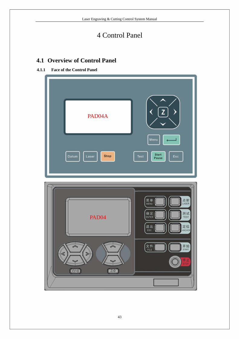
4.1 Overview of Control Panel
4.1.1 Face of the Control Panel
PAD04
PAD04A

Laser Engraving & Cutting Control System Manual
44
4.1.2 Function of the Keys
Datum (XY-0): Laser head moves to the original point of the machine slowly. It is mainly
used to estimate cumulative error. Make sure that the application of datum switch and lead the
switch signal to the controller.
Laser: Laser on/off.
Stop: Stop operation.
Test: The laser head will run along the outline border of the processing data.
Start/Pause: Start/pause the processing operation.
Esc: Escape the current status window.
Menu: Enter supporting interface.
: Click this button and switch to Z status (PAD04 has individual Z keys). Click “∧ ”
“∨ ”to move the Z axis. This function needs hardware support.
: Enter.
4.2 Start Interface
When system started, it is displayed as follows:
4.3 Main Interface
If there’s no communication problem with MPC65*5, main interface will be shown as
follows:
4.3.1 Description of Parameters
File: processing file name;
Speed: percentage of the processing speed;
Power: percentage of processing power. The first one is the power corresponding to low speed,
while the latter is the power corresponding to high speed.
Laser Engraving & Cutting Control System Manual
45
Pieces: repeat times of a processing file.
4.3.2 Cursor Appears (Initial Status)
Press < > to move the cursor and select the option want to modify;
Press ∧∨ to set the values of selected option, including processing speed, power
corresponding to low speed, power corresponding to high speed and pieces. Stepping=1;
Press ∧∨to select a file when the cursor is on “File”. If there’s no file in controller, no name
of file will be shown.
To delete a file: move the curse to DEL, and press ENTER;
To process a file: Press START.
Note:
Press ENTER to confirm the settings on speed, power and pieces. The parameters will not
lose when power off.
4.3.3 Cursor Disappear
Press ESC and the cursor disappear.
Press < > ∧ ∨ to move the laser head.
4.3.4 Laser
Press LASER to beam according to the settings of shooting;
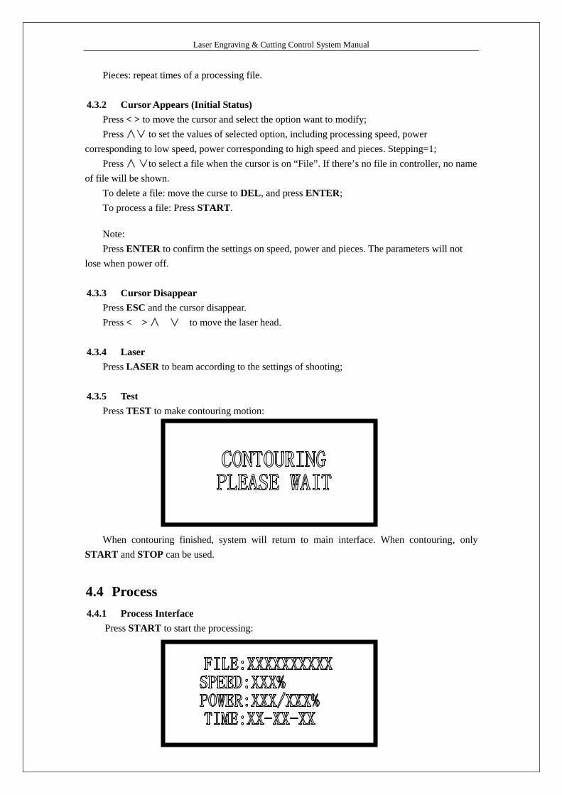
4.3.5 Test
Press TEST to make contouring motion:
When contouring finished, system will return to main interface. When contouring, only
START and STOP can be used.
4.4 Process
4.4.1 Process Interface
Press START to start the processing:

Laser Engraving & Cutting Control System Manual
46
Parameter descriptions are as follows:
File: processing file name;
Speed: percentage of the processing speed;
Power: percentage of processing power. The first one is the power corresponding to low
speed, while the latter is the power corresponding to high speed;
Time: processing time spent.
4.4.2 Process Control
During the process, only following buttons can work-- START, STOP, <, >, ∧, ∨:
Buttons ∧, ∨are used to change the processing speed. Stepping=1. The value ranged from
0-100.
Buttons <, > are used to change the power corresponding to high speed. Stepping=1. The
value ranged from 0-100.
Press START for odd times, it will enter pause interface and show as follows:
In this interface, only START and STOP buttons can work;
Press START for even times during processing, it will return from pause interface to process
interface.
Press “STOP”during the processing, it will stop the processing.
4.4.3 Download with USB Flash Disk
When a USB flash disk is plugged into the controller, main interface will show as follows:
Controller starts choose the process files once the USB flash disk is detected. Interface
displays as follows:
Laser Engraving & Cutting Control System Manual
47
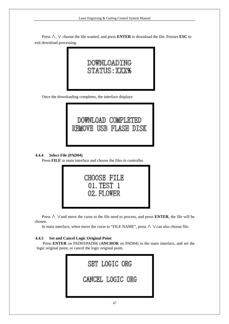
Press ∧, ∨ choose the file wanted, and press ENTER to download the file. Presses ESC to
exit download processing.
Once the downloading completes, the interface displays:
4.4.4 Select File (PAD04)
Press FILE in main interface and choose the files in controller.
Press ∧ ∨and move the curse to the file need to process, and press ENTER, the file will bechosen.
In main interface, when move the curse to “FILE NAME”, press ∧ ∨can also choose file.
4.4.5 Set and Cancel Logic Original Point
Press ENTER on PAD03/PAD06 (ANCHOR on PAD04) in the main interface, and set thelogic original point, or cancel the logic original point.

Laser Engraving & Cutting Control System Manual
48
Press < > and move the curse to the option, and press ENTER to confirm and return to themain interface.
This operation can set the current piont as logic original point, and the coordinate will besaved. But it is only effective when the machine successfully reset and “Immediate Output”isselected.
4.5Supporting Interface
Press MENU once to enter the supporting interface, which displays as follows:
Press MENU twice to enter another supporting interface, which displays as follows:
Press < > to move the cursor;
Press ENTER to confirm;
Press ESC to return to main interface.
4.5.1 Cutting Contour
Select CUT COUNTOUR by cursor and press ENTER:
When the machine is cutting contour, only START and STOP can be used.
It will return to the main interface once the motion completed.

Laser Engraving & Cutting Control System Manual
49
4.5.2 Laser Set
Select LASER SET by cursor and press ENTER:
The default value of time is 0 ms, default power value is100%;
Press < > to move the cursor to choose Time or Power;
Press ∧ ∨to set parameters, setting=1;
Time ranged from 0 to 99999ms. Power ranged from 0 to 100%. Press ENTER to make the
settings effective.
Press ESC to return to supporting interface while the settings won’t be effective.
If the time=0, laser will be on immediately upon pressing the button LASER, and be off
when stop pressing. If time is set to be a fixed value, laser will be on a certain time for each press.
4.5.3 Jog Set
Select JOG SET by cursor and press ENTER:
Press ∧∨ to set parameters. Press ENTER to confirm and return to supporting interface.
The default value =0, start moving upon pressing < > ∧ ∨, and stop when stop pressing. If
the value is not 0, laser head start moving a fixed distance at high speed.
4.5.4 IP Set
Press < > to move the cursor and press ∧ ∨to set parameters, setting=1;
Machine ID: When one LaserCut controls several machines, the machine ID should be set on
the PAD panel. It is suggested that the ID should not be the same.

Laser Engraving & Cutting Control System Manual
50
IP Mode: There are 2 modes to set the IP address of the controller, auto and static. The default
is “AUTO”.
When the mode is “STATIC”, you can input any number to identify different machine.
By “STATIC” mode, the PC can communicate with the controller in 1 second; and by
“AUTO”mode, it should be 10 second.
If there is a router between the PC and the controller, The PC can communicate with the
controller in 1 second no matter the mode is “AUTO”or “STATIC”.
4.5.5 Screen Protect
Select SCREEN PROTECT by cursor and press ENTER:
Press ∧ ∨ to set parameters. Press ENTER to confirm. Press ESC to return to supporting
interface while the settings won’t be effective.
4.5.6 Language Option
Select LANGUAGE by cursor and press ENTER:
Press ∧ ∨to set parameters. Press ENTER to confirm. Press ESC to return to supportinginterface while the settings won’t be effective.
If without pressing any button to set a language, system will choose the language where the
cursor is and return to the supporting interface automatically in 5 minute.
4.5.7 Alarm Time
Select ALARM TIME by cursor and press ENTER:

Laser Engraving & Cutting Control System Manual
51
Press ∧ ∨ to set parameters. Press ENTER to confirm. Press ESC to return to supporting
interface while the settings won’t be effective.
4.6Error Alarm Interface
If there’s any failure of the system, PAD** can display the error, and the user can find the
error immediately.
4.6.1 Soft Limit Error
Cause:The system detected that the process data size exceed the workplace range.Solution:Move the laser head to correct place and run again.
4.6.2 Limit Switch Error
Cause:The machine has not been reset and the user chooses the “Immediate Output”mode.Solution:Move the laser head to correct place and run again.
4.6.3 Memory Alarm
Cause:
1. These are more than 32 files in the controller.

Laser Engraving & Cutting Control System Manual
52
2. All the files in the controller exceed 128M.
Solution:
Delete some files and re-download process file.
4.6.4 Configuration doesn’t Match the Firmware
Cause:Process file or configuration file doesn’t match with the firmware version.Solution:Replace the DLL with the correct one matching with the firmware version, and download theconfiguration file.
4.6.5 Dll Version doesn’t Match with the Firmware
Cause:Incorrect DLL has been used in the software.Solution:Replace the correct DLL in the software, delete all the files in controller, and re-download the
process files.
4.6.6 Dll Version doesn’t Match with the Firmware
Cause:Incorrect firmware file (*.fmw) has been downloaded to the controller.Solution:Re-download correct firmware file.

Laser Engraving & Cutting Control System Manual
53
5 Appendix
5.1 IP Set
There are 2 modes to set the IP address of the controller, auto and static. The default is
“AUTO”.
When the mode is “STATIC”, you can input any number to identify different machine.
By “STATIC” mode, the PC can communicate with the controller in 1 second; and by
“AUTO”mode, it should be 10 second.
If there is a router between the PC and the controller, The PC can communicate with the
controller in 1 second no matter the mode is “AUTO”or “STATIC”.
5.2 How to control several machine in one software
5.2.1 Wiring Diagram
5.2.2 Set IP Mode
Set the IP mode as “AUTO”on the PAD panel.

Laser Engraving & Cutting Control System Manual
54
5.2.3 Set Machine ID
Set the machine ID on the PAD panel.
It is suggested that the ID should not be the same.
5.2.4 Networking
Connect all the controller to the router by net cable, and the router connects with the PC.
5.2.5 Identify the machine ID
Power on the machines and run the LaserCut61, the software will get the IP address of the
machines automatically and show the machine ID.
5.2.6 Choose machine ID and download data
Before download data, machine ID should be choose firstly.
5.3Quick Operation
5.3.1 Right Key of the Mouse
At different situation, click right key of the mouse to get to the tools quickly.
When there is nothing in the drawing area, click right key and is shows as below:
When selected graphics, click right key and is shows as below:
There is graph in the drawing area. Without selecting any graphics, click right key and is
shows as below:

Laser Engraving & Cutting Control System Manual
55
5.3.2 Ctrl+A
Select the entire graph in the drawing area.
5.3.3 Ctrl+Y
Move the selected graph to the center of the drawing area.
Without selecting any graphics, the whole graph will be moved to the center of the drawing
area.
5.4Description of Auto Separation 2-Head Machine
5.4.1 Working condition
The system supports the single-belt auto separation 2-head machine as follows.
There are 2 laser heads on the X-Axis and they are fixed on one belt.
5.4.2 Set the machine parameters
Set the Z-Axis as “2-Head”in “Axis CFG”as follows:

Laser Engraving & Cutting Control System Manual
56
Set the “Power Mode”as “Double Laser Analog”in “Motion Card CFG”as follows:
Set parameters about auto separation 2-head in “Application CFG”as follows:
2-Head Mode: Auxiliary head is the laser head that is controlled by the motor (M2). The
motor can move on the X-Axis. LASER1 in the upper figure is auxiliary head and “辅助头在左”
should be selected.
Min Distance between 2 Head: The distance between the two laser-head after datum. The
value should be measured accurately.
Download the Machine CFG after the machine parameters have been set.
5.4.3 Graph typeset operation
This function is only used for cutting vector graphics.
5.4.3.1 Select “Auto 2-Head”mode

Laser Engraving & Cutting Control System Manual
57
5.4.3.2 Import data and set processing parameters
Import data and set layers. Set the processing parameters of each layer.
5.4.3.3 Group the graphics
Group the graph entities into one graphic unit.
5.4.3.4 Virtual Array
Set virtual array parameters.

Laser Engraving & Cutting Control System Manual
58
5.4.3.5 Download processing file
Download the processing file to the controller and start the processing.
5.5 Make AI File
Cutting the AI Format is smoother, and makes less strike, especially of constant speed. It is
suggested to use AI Format File as much as possible. If some obvious strike in cutting of varied
speed, and the figure distorted, change the file to PLT.

Laser Engraving & Cutting Control System Manual
59
5.6 Backlash Adjustment of Engraving
In engraving of high speed, burr may appear in the processing edge due to the tightness of thebelt. It appears as below:
There is Backlash Compensation set in the Engrave Set of the Machine CFG. The backlashcan be negative or positive value. Change the engrave step to 2mm, backlash 1mm, and startprocessing. If d increase, change it to a negative value; if d decreases, increase the number.Gradually d will near 0 after several adjustments. The value of the Backlash Compensation differsfrom different speed; you should set it according to different speed range.
d

Laser Engraving & Cutting Control System Manual
60
5.7 FQA
5.7.1 PLT figure can’t be engraved
The graph is unclosed or overlapped. Please use the “Check Data”tool to check if there are
such occasions.
5.7.2 Size of the output of engrave/cut is not the same with the graphics
Please adjust the “Pulse Unit”.
5.7.3 When engraving, the edge is not in order
It is mainly caused by the backlash. You can adjust it as follow:
a) Draw a rectangle, set the 0.5mm in “Laser Engrave”and “Engrave Step”. Theoretically,
the engrave result will be ok, that is, edges of the odd lines are in order and edges of the even lines
are in order. But odd lines and even lines may not be in order.
b) Open “Set Engrave Options”, there are different processing parameters for different speed
range. But set values in the “Backlash”are all 0. You can set the value according to the actual
situation, both negative and positive.
c) If you require a better engrave result, choose one direction laser on. Uncheck the “Bi-Dir”
will do. But this will decrease the process efficiency.
5.7.4 Axis doesn’t move (MPC6585)
Set direct voltage 5V by a multimeter, measure the voltage between PUL and GND. Take
Y-axis as an example. Press up or down button, the normal value is about 2.8V. If it is not,
controller is damaged. Please change controller. If it is, step on.
Change the output terminals of the two drivers, and press up or down button. If X-axis is
right, then Y-axis motor is damaged. Please replace Y-axis motor. If X-axis does not move, then
Y-axis driver is damaged. Please replace Y-axis driver.
5.7.5 Axis can only move to one direction (MPC6585)
Set direct voltage 5V by a multimeter, measure the voltage between DIR and GND. Take
X-axis as an example. Press left and then right button to see if there are changes of the voltage
(higher than 2.8V or lower than 0.8V). If not, the controller is damaged. Please replace it. If yes,
check if the driver is ok.
5.7.6 Laser always off (MPC6585)
Set direct voltage 5V by a multimeter, test the voltage between LAS and GND. Press “Laser”
on the control panel to see if there are changes of the voltage (higher than 2.8V or lower than
0.8V). If not, controller is damaged, please replace it.
Moreover, set 0ms in the “Time”of the laser in the control panel PAD (laser time after you
stop pressing the laser on button). Adjust the power (0%~100%), press “Enter”and press the
“Laser”button. Measure the voltage change between DA and GND. It should be varied from
0~5V. If there is not, controller is damaged. Please replace it.
If the controller is OK, laser power supply is damaged. Please replace it.