
Laser Control Software (LabView) - EdgeWave GmbH 4 3. Operation 3 Operation 3.1 Main window When...
35
Laser Control Software (LabView) User Manual EdgeWave GmbH Innovative Laser Solutions
Transcript of Laser Control Software (LabView) - EdgeWave GmbH 4 3. Operation 3 Operation 3.1 Main window When...

Laser Control Software (LabView) User Manual
EdgeWave GmbH Innovative Laser Solutions

EdgeWave Laser Control Software (LabView) Copyright c 2010 EdgeWave GmbH
Doc. Ver. 1.0.3 - February 18, 2017
Every effort has been made to ensure that the data given in this document is accurate. The information, figures, tables, specifications and schematics contained here in are subject to change
without notice. EdgeWave makes no warranty or representation, either expressed or implied with
respect to this document. In no event will EdgeWave be liable for any direct, indirect, special, incidental or consequential damages resulting from any defects in its documentation.
This manual is based on EdgeWave Laser Control version 1.1.0 and above. The version of the
software can be found in the settings tab by clicking on the info button.
EdgeWave GmbH Carlo-Schmid-Str. 19 D-52146 Würselen
Germany Tel: +49(0)2405-4186 0
Fax: +49(0)2405-4186 33 Email: [email protected]
Internet: http://edge-wave.com

Table of Content
1. Safety ........................................................................................................................ 1
2. Installation ................................................................................................................. 2
2.1 File list ................................................................................................................. 2
2.2 Requirement ......................................................................................................... 2
2.2.1 Hardware requirement .................................................................................... 2
2.2.2 Software requirement ...................................................................................... 2
2.3 Software installation and uninstalling ...................................................................... 3
2.3.1 Installation ..................................................................................................... 3
2.3.2 Uninstalling .................................................................................................... 3
3 Operation ................................................................................................................... 4
3.1 Main window ........................................................................................................ 4
3.2 Terms .................................................................................................................. 8
3.3 Regular Operation ............................................................................................... 14
3.3.1 Laser Operation Panel ................................................................................... 14
3.3.1.1 Laser Operation Panel (Nano Second Laser) .............................................. 14
3.3.1.2 Laser Operation Panel (Pico Second Laser) ............................................... 17
3.3.2 Tab Control Panel ......................................................................................... 20
3.3.2.1 Current Control Tab ................................................................................ 20
3.3.2.2 Oven Control Tab ................................................................................... 21
3.3.2.3 Advanced Info Tab ................................................................................. 22
3.3.2.4 Settings Tab ........................................................................................... 24
3.3.2.5 Chiller Control Tab .................................................................................. 25
4 Options ..................................................................................................................... 28
4.1 Laser Connection Settings .................................................................................... 28
4.2 Hot Keys ............................................................................................................ 30
4.3 Preset Currents ................................................................................................... 30
4.4 Save Settings ...................................................................................................... 31


EdgeWave GmbH
1
1. Safety
1. Safety
The EdgeWave Laser Control Software is intended to control an EdgeWave
INNOSLAB laser through a serial (RS232) port of the computer. Laser radiation
may affect a person's health or may otherwise cause damage. Prior to installation and operation compliance with all relevant laser safety regulation has to be
secured. The client shall solely be responsible to strictly comply with all applicable and relevant safety regulations regarding installation and operation of the system
at any time.

EdgeWave GmbH
2
2. Installation
2. Installation 2.1 File list
The EdgeWave Laser Control Software is delivered with the following file(s):
• Laser Control.exe Laser Control which provides the full control to the Laser via RS232 (serial) port.
• Settings.ini The file used to save all settings for the EdgeWave Laser Control Software.
• Data (Folder)
LabView runtime engine needs the Dll-files in this folder to run the Laser Control Software.
2.2 Requirement 2.2.1 Hardware requirement
• The EdgeWave Laser Control Software is designed to control EdgeWave INNOSLAB Laser. An EdgeWave Laser with essential peripheral equipment, e.g.
EdgeWave Power Supply, chiller, trigger generator, etc. is required.
Please read the manual of EdgeWave Laser carefully and connect all cables
properly prior to use EdgeWave Laser Control Software.
• A computer to control the Laser.
◦ A serial (RS232) port is required to control an EdgeWave Laser with
EdgeWave Laser Control Software. Both on-board com port and USB to RS232 adapter works.
◦ 10MB free hard drive space. ◦ The software itself will use less than 50MB memory when running, which
can be provided by any modern computer.
◦ A monitor with a resolution of min. 1280x720 pixels.
2.2.2 Software requirement
• EdgeWave Laser Control Software works only in Windows™ platform, including both 32 and 64 bits version of Windows XP, Windows Vista, Windows 7
or above.
• LabView run-time engine 2010 (32-bit standard RTE) and NI-Visa 5.1 RTE or
above. (The RTE can be downloaded from Ni homepage www.ni.com)

EdgeWave GmbH
3
2. Installation
• Windows user privilege
◦ The EdgeWave Laser Control Software writes all settings into Settings.ini in the same directory when it is closed. The setting file will be created
automatically in case of missing. The Modify, Create and Read privilege to file Settings.ini must be granted to current user to avoid some warning
message.
◦ The software controls an EdgeWave Laser via the serial (RS232) port. The read and write privilege to the using serial port has to be granted.
2.3 Software installation and uninstalling
The EdgeWave Laser Control Software is a green software which means
NOTHING will be written into the registry or system folder by itself.
2.3.1 Installation
1. Copy all files delivered into the destination directory. 2. Create a shortcut to the preferred location. For instance, a shortcut will be
created on the desktop of Windows by right clicking on Laser Control.exe with the
mouse and then select “Send To” → “Desktop (create shortcut)”, as shown below:
Figure 1: Create a shortcut on desktop
2.3.2 Uninstalling
1. Delete the shortcut pointed to Laser Control.exe. 2. Delete Laser Control.exe, Settings.ini and any other files and folders
copied with this software under the directory of EdgeWave Laser Control.

EdgeWave GmbH
4
3. Operation
3 Operation 3.1 Main window
When launch the Laser Control Software for the first time, it will try to connect
EdgeWave Laser via a serial port. If no EdgeWave Laser is connected (Figure 2), it will try to reconnect automatically for every 5 seconds If search for laser periodically option is activated (checked). Both serial port and the auto-connect
feature are adjustable in the Settings tab.
Figure 2: Settings tab – Laser disconnected
To establish a connection to the laser, the following requirement must be fulfilled:
• An EdgeWave laser is connected to a working serial port of the computer.
• The RS232 cable used to connect the laser and the computer must be a 1-to-1
cable.
• Serial port number has to be specified in the laser control software correctly. If
the Auto select port option is not checked.
• Emergency stop button of the laser has to be released.
• Safety loops on the rear panel of laser power supply is connected properly and
the corresponding switches are closed. Please find more details about safety loops in the user manual of EdgeWave Laser.
• The Laser power supply is connected to the mains and switched on.

EdgeWave GmbH
5
3. Operation
Once the laser is found and connected, Laser Operation panel (Figure 3) will
appear. This panel provide an easy way to set most of laser parameters and
displays warnings or errors. The Current Control tab (Figure 3) displays the current status. Please refer to section 3.3.1 for detailed information.
Figure 3: Laser operation panel and current control tab – Nanosecond laser
If a pico second laser is connected, advanced setting for pico second laser (Figure
4) will appear. The high voltage level of the modulator, modulator mode and the pulse picker settings can not be changed while the laser is on. Please refer section
3.3.1.2 for more information.
Figure 4: Laser operation panel and current control tab – Pico second laser

EdgeWave GmbH
6
3. Operation
In the Oven Control tab (Figure 5) the activated ovens will shown. Ovens will be
activated automatically during connecting the laser. In the Advanced Info tab
(Figure 6) there is the possibility to activate or deactivate the ovens individually. Please refer to section 3.3.2.2 for more information.
Figure 5: Oven control tab
Information (e. g. Serial number, humidity or cooling water settings) about the connected laser are displayed in the Advanced Info tab (Figure 5). In this tab a
terminal can be activated, with which all control commands of EdgeWave Laser can
be executed. Please refer section 3.3.2.3.
Figure 6: Advanced info tab – Nanosecond laser

EdgeWave GmbH
7
3. Operation
A Termotek chiller with a serial interface (RS232) can be controlled over the Chiller Control tab (Figure 7). It allows a simple control of a chiller (e. g. water
temperature set point and turn on/off the chiller) and displays the outlet water temperature and water flow rate.
Figure 7: Chiller control tab. – chiller disconnected
To establish a connection to a chiller, the following requirement must be fulfilled:
• A Termotek chiller is connected to a working serial port of the computer.
• The RS232 cable used to connect the laser and the computer must be a 1-to-1
cable.
• Serial port number has to be specified in the chiller control tab correctly. If the
Auto select port option is not checked.
• The chiller is connected to the mains and switched on.

EdgeWave GmbH
8
3. Operation
3.2 Terms
The terms below are subject to the use of EdgeWave Laser. Their definition is important in understanding the operation procedure, trouble shooting and so on.
Some of the definitions are valid only inside this manual and during operating EdgeWave Laser.
Laser output
Laser output means required laser beam emitting from the output aperture of the laser head. To have laser output, the following must be fulfilled if the
other necessary parts (e.g. cooling water) are configured properly and working well:
1. Laser ON 2. The current is higher than the threshold
3. Proper TTL trigger signal is provided if working in External trigger mode
4. Proper TTL trigger signal for external modulator is provided if
required
Laser ON/Off
When Laser On/Off is set, the control board has to prepare some initializing procedures for laser output, e.g. set the current of Laser diodes to nominal
value and turn the shutter to output position if present.
The diode current and pulse picker settings of a pico second laser can not be changed and will be deactivated while laser on.
Laser ON should be considered more like “Laser is ready for ON”. To have laser beam output, all conditions for Laser output described above must be
fulfilled.
When laser is Off, current of Laser diodes is set to 0A despite of the nominal
current and the shutter is turned to off position (if present).
Q-Switching
Most of EdgeWave lasers are working at Q-switching mode, which is a technique to produce pulsed output beam with high peak power and short
pulse width. It is achieved by putting an optical switch inside the laser's
optical resonator. Normally there is not pulse output when the switch is off, while a giant pulse is produced once it switches to on.
Trigger
The TTL signal used to control the on/off state of the Q-switch. It controls
the repetition rate and the timing of laser pulses. It also regulates the pulse
energy in some kinds of EdgeWave laser.

EdgeWave GmbH
9
3. Operation
Trigger mode
Control mode of the Q-switch in EdgeWave laser. There are 3 kinds of mode: CW (continuous wave), External trigger and Internal trigger.
External trigger
The trigger signal is generated outside of EdgeWave laser and coupled into the laser through the trigger port of the laser. This is the
most favourable mode for most applications because the user can control the timing and the other features.
Internal trigger
The trigger signal is generated by the control board of EdgeWave
laser. It is not controllable by user. For some model the internal trigger signal might becomes unstable at >5kHz.
CW
The Q-switch does not work under CW mode. The laser resonator will
have constant output if there is enough pump power.
Internal Frequency
The internal trigger frequency is generated by the control board in laser.
In some lasers equipped with certain first pulse killer, the frequency set here
also tells the controller to perform the pulse optimizing according to this
frequency. For such laser, the maximum working frequency must be set here. Otherwise the laser might be locked down at lower power level, or
pulse energy is unstable.
Laser status indicator
The status indicator on the right side of the Laser On/Off control displays
the actual status of the laser analogue to the status LED on the laser head and power supply of some lasers.
The blue color of the Status indicator displays that the laser is
ready to use.
If the laser is on the color of the Status indicator changes to
green
On any error the Status indicator changes its color to red.

EdgeWave GmbH
10
3. Operation
High voltage settings (Pico second laser)
The high voltage level of the modulator regulates the avg. laser power of pico second laser. While the laser is on, the set point of the current can not
be changed. By changing the high voltage level from 30% to 100%, the avg. power of the laser can be manipulated.
Please note that the high voltage level does not correspond with the avg. laser power. The Pmax@HV-level displays the high voltage level set point at
which max. laser power can be emitted.
HV-Modulator mode (Pico second laser)
Control mode of the modulator in EdgeWave pico second laser. There are 4 kinds of mode: HV Always on, HV Always off, External and Internal.
Internal
The internal signal is generated by the control board of laser. The
maximum frequency is displayed on the HV-Modulator Mode control element. If changed to Internal mode an input field for the duty cycle
frequency will appear.
External
The signal is generated outside of EdgeWave laser and coupled into the laser through the trigger port of the laser. This is the most
favourable mode for most applications because the user can control
the timing and the other features. An external function generator can be synchronized through the sync. output of the laser head.
The maximum frequency is displayed on the HV-Modulator Mode control element.
HV Always off
The modulator is turned off. No pulses will be emitted. This is the best
way to turn of the laser power for a short time.
HV Always on
The modulator is on. This means that every laser pulse will be emitted which is picked by the pulse picker.
EdgeWave GmbH
11
3. Operation
Duty cycle frequency
The duty cycle signal can be generated by the laser control board or by an external function generator.
Laser pulses will emit only in the positive width of the signal. The maximum frequency, which can be used, is displayed on the HV-Modulator Mode
control element.
The duty cycle signal can be used only if HV-modulator mode is switched to
internal or external mode. If modulator mode changed to internal mode an input field for the duty cycle frequency will appear.
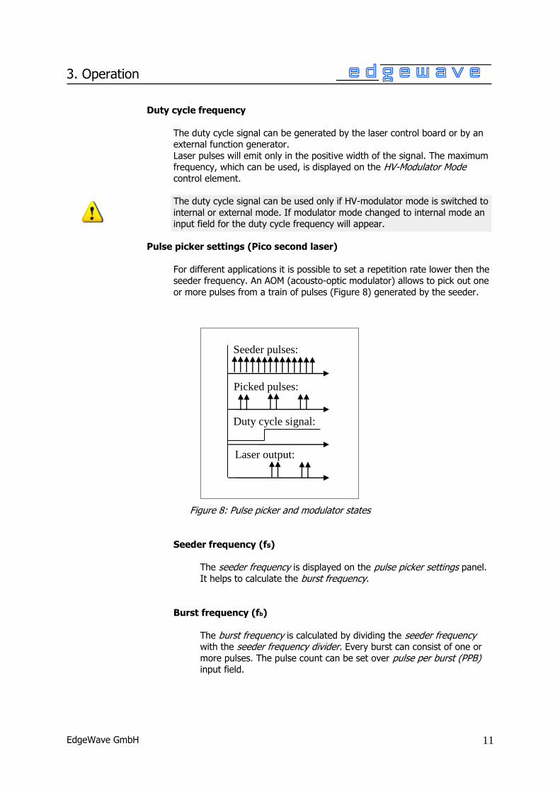
Pulse picker settings (Pico second laser)
For different applications it is possible to set a repetition rate lower then the seeder frequency. An AOM (acousto-optic modulator) allows to pick out one
or more pulses from a train of pulses (Figure 8) generated by the seeder.
Figure 8: Pulse picker and modulator states
Seeder frequency (fs)
The seeder frequency is displayed on the pulse picker settings panel.
It helps to calculate the burst frequency.
Burst frequency (fb)
The burst frequency is calculated by dividing the seeder frequency with the seeder frequency divider. Every burst can consist of one or
more pulses. The pulse count can be set over pulse per burst (PPB) input field.
Seeder pulses:
Picked pulses:
Duty cycle signal:
Laser output:

EdgeWave GmbH
12
3. Operation
Seeder frequency divider (SFD)
An integer value can be set to divide the seeder frequency. To set a different SFD laser must be off.
Please note that by higher SFD values the amplifier current (I2) is
limited! To be able to set a higher SFD the amplifier current must be
set correct. A frequency current table on the Advanced Info tab (Figure 9) shows the possible settings.
Figure 9: Frequency current table – Advanced Info tab
Pulse per burst (PPB)
An integer value can be set to change the pulse count per burst. If
PPB is zero no pulse will emit!
EdgeWave GmbH
13
3. Operation
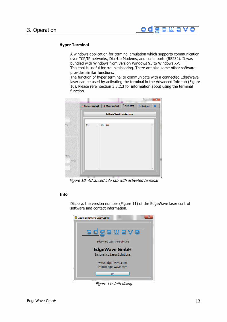
Hyper Terminal
A windows application for terminal emulation which supports communication over TCP/IP networks, Dial-Up Modems, and serial ports (RS232). It was
bundled with Windows from version Windows 95 to Windows XP. This tool is useful for troubleshooting. There are also some other software
provides similar functions.
The function of hyper terminal to communicate with a connected EdgeWave laser can be used by activating the terminal in the Advanced Info tab (Figure
10). Please refer section 3.3.2.3 for information about using the terminal function.
Figure 10: Advanced info tab with activated terminal
Info
Displays the version number (Figure 11) of the EdgeWave laser control software and contact information.
Figure 11: Info dialog

EdgeWave GmbH
14
3. Operation
3.3 Regular Operation
The regular operation window provides a GUI (graphical user interface) to interact
with an EdgeWave laser. Only a few value inputting and mouse clicking are
required with such panel to control the Laser. Most of laser operation can be done here.
3.3.1 Laser Operation Panel
Laser Operation panel is located at the left side of the window. If a nano second laser is connected (Figure 12), the panel will be visible. If a pico second laser is
connected, advanced controls and indicators will appear (Section 3.3.1.2).
3.3.1.1 Laser Operation Panel (Nano Second Laser)
The Laser Operation panel for nano second laser consists of the input fields for Trigger Mode, Internal Frequency, indicators for Laser Status, laser warning and
error.
Figure 12: Main operation panel
Laser On/Off control and Laser Status indicator
Trigger Mode and Internal Frequency control
Laser Warning, Error indicator
and Clear Error control
Control buttons

EdgeWave GmbH
15
3. Operation
Laser On/Off Control
To turn on or off the laser. Please refer to section 3.2 for the definition of laser on and off
Laser Status Indicator
It shows the laser on, off and error status of the laser. Please refer to
section 3.2 for detailed information.
Trigger Mode Control
The trigger mode can be changed easily by clicking the corresponding control (Figure 13). The trigger
modes are: Internal, external and CW (continuous wave). Please refer to section 3.2 for the definition
of trigger modes.
Figure 13: Trigger Mode control
Internal Frequency
An internal trigger frequency in kHz can be input here.
In some Lasers equipped with certain first pulse killer, the frequency set
here also tells the controller to perform the pulse optimizing according to this frequency. For such Laser, the maximum working frequency must be set
here. Otherwise the Laser might be locked down at lower power level, or pulse energy is unstable.

EdgeWave GmbH
16
3. Operation
Laser warning
It shows laser warning messages. If the warning limits reached (e. g. water temperature too high or low) a warning text will be displayed.
Laser Error
It shows laser error messages. If an error occurs the laser will turn off and
Laser Status indicator becomes red. Laser is locked down and can not be turn on until the error not solved. To release the laser from lock down state
the Clear error button must be used.
Clear Error
If laser error happened and solved, click this button to try to clear error message and release the laser from lock down state.
Reset
Click the reset button to perform a cold start. By doing this the laser will be
turned off (if it is on) and all settings will be restored to the default value saved before (using Save Settings button)
Save Settings
Save all settings (including trigger frequency and mode, nominal current,
etc.) into laser controller as default values. Once saved, those settings will
be restored after next reset or starting up the power supply.

EdgeWave GmbH
17
3. Operation
3.3.1.2 Laser Operation Panel (Pico Second Laser)
In case of connecting a pico second laser, advanced controls and indicators will
appear (Figure 14).
The pico second laser panel consists of two sub panels: High voltage modulator panel and pulse picker settings panel.
Figure 14: Main operation panel – Pico second laser
High Voltage Level Panel
The high voltage level of the modulator regulates the avg. output power of pico second laser. Please refer section 3.2 for more information.
Pmax @ HV-level
It shows the high voltage level at which the avg. output power of the
laser has its maximum.
HVset
High voltage level should be input in this input field.
HVact.
It shows the actual high voltage level
HV-Modulator panel
Pulse picker settings
panel.

EdgeWave GmbH
18
3. Operation
HV-Modulator Mode Panel
HV-Modulator Mode
Control mode of the modulator in EdgeWave pico second laser. There are 4 kinds of mode (Figure 15): HV Always on, HV Always off, External and
Internal. Please refer section 3.2 for detailed information about the
modulator modes.
Figure 15: High Voltage Modulator panel
Duty Cycle Frequency
The duty cycle frequency for the internal modulator mode can be
input here. Please refer section 3.2 for more information.
HV Mod. Activated?
It shows if the high voltage modulator is activated. The modulator can
be activated or deactivated with the command: w178 X (X = 0 to deactivate, X = 1 to activate modulator)
If HV. modulator is deactivated, the laser can not emit any pulses.

EdgeWave GmbH
19
3. Operation
Pulse Picker Settings Panel
This panel allows to set seeder frequency divider and shows the burst frequency (Figure 16). Please refer section 3.2 for the definitions and
detailed information.
Figure 16: Pulse Picker Settings panel
fseed (Seeder Frequency)
The seeder frequency is displayed here. It is needed to calculate the burst frequency.
fb (Burst Frequency)
The burst frequency is calculated by dividing the seeder frequency
with the seeder frequency divide (SFD).
SFD (Seeder Frequency Divider)
An integer value from 1 to 16 000 can input here. It divides the
seeder frequency to allow repetition rates lower then the seeder frequency. Nominal value is sent to the controller only after press
enter key in the edit box.
Please note that by higher SFD values the amplifier current (I2) is limited! To be able to set a higher SFD the amplifier current must be
set correct. A frequency current table on the Advanced Info tab
(Figure 9 and 19) shows the possible settings.
PPB (Pulse Per Burst)
Every burst can consist of one or more pulses. The pulse count can be set from 0 to SFD value here.
The PPB value must be lower or equal to SFD. If PPB is zero, no
pulses will emit!
EdgeWave GmbH
20
3. Operation
3.3.2 Tab Control Panel
The tab control panel consists of five tabs:
Current Control, Oven Control, Advanced Info, Settings and Chiller Control.
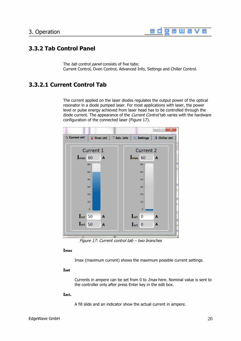
3.3.2.1 Current Control Tab
The current applied on the laser diodes regulates the output power of the optical resonator in a diode pumped laser. For most applications with laser, the power
level or pulse energy achieved from laser head has to be controlled through the diode current. The appearance of the Current Control tab varies with the hardware
configuration of the connected laser (Figure 17).
Figure 17: Current control tab – two branches
Imax
Imax (maximum current) shows the maximum possible current settings.
Iset
Currents in ampere can be set from 0 to Imax here. Nominal value is sent to the controller only after press Enter key in the edit box.
Iact.
A fill slide and an indicator show the actual current in ampere.
EdgeWave GmbH
21
3. Operation
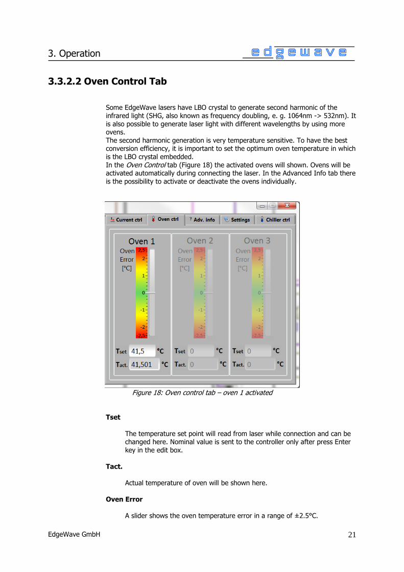
3.3.2.2 Oven Control Tab
Some EdgeWave lasers have LBO crystal to generate second harmonic of the
infrared light (SHG, also known as frequency doubling, e. g. 1064nm -> 532nm). It
is also possible to generate laser light with different wavelengths by using more ovens.
The second harmonic generation is very temperature sensitive. To have the best conversion efficiency, it is important to set the optimum oven temperature in which
is the LBO crystal embedded.
In the Oven Control tab (Figure 18) the activated ovens will shown. Ovens will be activated automatically during connecting the laser. In the Advanced Info tab there
is the possibility to activate or deactivate the ovens individually.
Figure 18: Oven control tab – oven 1 activated
Tset
The temperature set point will read from laser while connection and can be changed here. Nominal value is sent to the controller only after press Enter
key in the edit box.
Tact.
Actual temperature of oven will be shown here.
Oven Error
A slider shows the oven temperature error in a range of ±2.5°C.
EdgeWave GmbH
22
3. Operation
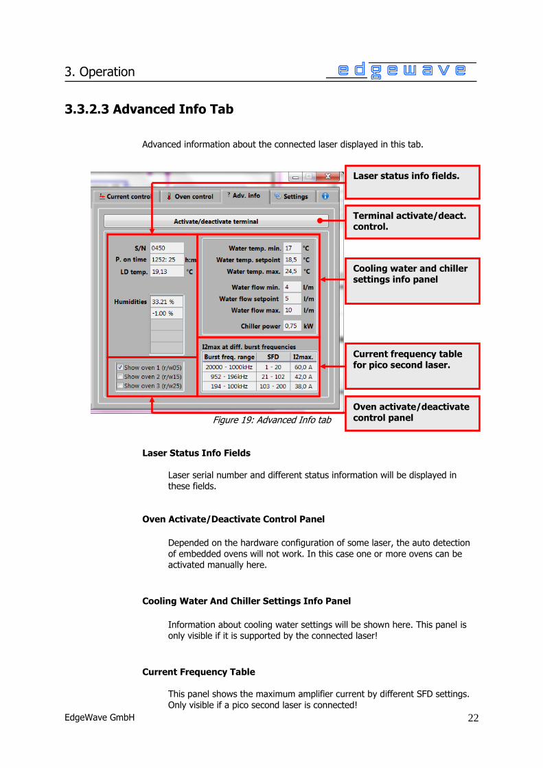
3.3.2.3 Advanced Info Tab
Advanced information about the connected laser displayed in this tab.
Figure 19: Advanced Info tab
Laser Status Info Fields
Laser serial number and different status information will be displayed in
these fields.
Oven Activate/Deactivate Control Panel
Depended on the hardware configuration of some laser, the auto detection
of embedded ovens will not work. In this case one or more ovens can be activated manually here.
Cooling Water And Chiller Settings Info Panel
Information about cooling water settings will be shown here. This panel is only visible if it is supported by the connected laser!
Current Frequency Table
This panel shows the maximum amplifier current by different SFD settings.
Only visible if a pico second laser is connected!
Terminal activate/deact. control.
Laser status info fields.
Cooling water and chiller settings info panel
Current frequency table for pico second laser.
Oven activate/deactivate control panel

EdgeWave GmbH
23
3. Operation
Terminal Panel
The terminal panel (Figure 20) will be shown by activating it over the Terminal Activate/Deactivate control or using hot key (Figure 24).
This panel is a terminal-like window for all commands that EdgeWave laser supports. Since the GUI provides basic controls only, the unimplemented
commands must be carried out here or use terminal emulation software
(e.g. HyperTerminal) instead.
Figure 20: Advanced Info tab – terminal panel activated
The terminal panel consists of input box, command history list and message box.
Input Box
A command should be input in this box. Press Enter key when the input focus is inside this box to send out a non-empty command
(empty command means spaces only).
In a terminal emulator, e.g. HyperTerminal, keystroke is sent out
immediately. As a result, improper key sequence cannot be corrected. Unlike it, the command can always be revised inside the input box
before sent out.
Input box
Message box
Command history list
Terminal activate/deact.
control.

EdgeWave GmbH
24
3. Operation
Command History List
This box holds a list of recently used commands. Once a command is send through the input box, it will be appended to the end of the
history list. To resend one of command, just double click with the left button of the mouse on the item.
Message Box
Messages received from laser are displayed here. The content can be
copied by using the windows hot key “Ctrl + C”.
3.3.2.4 Settings Tab
The Settings tab consists of laser connection panel, hot keys panel and an info
button (Figure 21), which shows the info dialog. Please refer section 4 for more information.
Figure 21: Settings tab
Laser Connection Settings Panel
Options for laser connection. Please refer section 4 for detailed information.
Hot Keys Panel
Configuration panel for hot keys. Please refer section 4 for detailed
information.
Hot keys panel
Laser connection settings panel
Info button

EdgeWave GmbH
25
3. Operation
3.3.2.5 Chiller Control Tab
The EdgeWave laser systems will be delivered in combination with a chiller. The
most chiller have a serial port (RS232) to control it by a computer. In this tab (Figure 22) it is possible to control the chiller.
Figure 22: Chiller Control tab
Chiller Connection Control Panel
In this panel the connection settings can be changed and a manually
connection to a chiller can be done. The settings will be saved at program end.
Connect Button
By clicking on Connect button the software will try to establish a
connection to the chiller which is connected over a free serial port to computer.
The connection can be established only if the requirements in section
3.1 are fulfilled.
Auto Select Port Control
If enabled (checked) it detects the serial port automatically if a chiller
is connected over a free serial port.
Main control panel
Water temp. panel
Water flow rate panel
Chiller connection control panel

EdgeWave GmbH
26
3. Operation
Select Serial Port Control
Serial port number has to be specified correctly. If the Auto select port option is not checked. The software can enumerate the serial
ports present in the computer which will be shown when click the down arrow in the drop-down list control.
Connect To Chiller At Start Up
If enabled (checked) the software will try to connect to a chiller at
program start up.
Main Control Panel
It consists of a control element, a few indicators and message boxes.
Chiller On/Off Control
The connected chiller can turn on or off by activating or deactivating this control.
If trying to turn off chiller and connected laser is on, a dialog will pop
up to warn that the laser is on. It is possible to turn off laser and
chiller at same time or cancel the operation.
Chiller On/Off Indicator
It shows if chiller is on or off. The color of the indicator is green if chiller is on else black.
Chiller Error box
On error or warning a message will be displayed here.
If the chiller is turned off, a message will be displayed and the Chiller error indicator will change its color to red.
Chiller Error Indicator
On error or warning the color of the indicator is red, else green.

EdgeWave GmbH
27
3. Operation
Water Temperature Panel
In this panel the cooling water temperature can be changed. Tact. and a slider show the actual outlet water temperature.
Tset
The temperature set point will read from chiller while connection and
can be changed here. Nominal value is sent to the controller only after press Enter key in the edit box.
The water temperature can be set between 17°C and 30°C
Tact.
Tact. and a slider show the actual outlet water temperature
Water Flow Rate Panel
Act. flow and a slider shows the actual water flow rate in this panel.

EdgeWave GmbH
28
4. Options
4 Options
The Settings tab consists of laser connection, hot keys, preset panel and an info
button (Figure 23), which shows the info dialog.
Figure 23: Settings tab
4.1 Laser Connection Settings
To establish a connection to laser, the following requirement must be
fulfilled:
• An EdgeWave laser is connected to a working serial port of the computer.
• The RS232 cable used to connect the laser and the computer must be a
1-to-1 cable.
• Serial port number has to be specified in the laser control software correctly. If the Auto select port option is not checked.
• Emergency stop button of the laser has to be released.
• Safety loops on the rear panel of laser power supply is connected properly and the corresponding switches are closed. Please find more details about
safety loops in the user manual of EdgeWave Laser.
• The Laser power supply is connected to the mains and switched on.
Hot keys panel
Section 4.2
Preset currents panel
Section 4.3
Laser connection settings Section 4.1
Info button
Section 4.4

EdgeWave GmbH
29
4. Options
Connect Button
To connect or disconnect a laser.
Connection Indicator
If no laser is connected, the indicator is dark green. When the software tries to connect a laser, it changes its color to yellow. The indicator has the color
bright green, if the software is connected to a laser.
Auto Select Port
The Laser Control software enumerates the serial (RS232) ports present in the computer. If this option is activated, the software tries to open the ports
and sends a command (r01 for serial number).
Select Serial Port
The software has to know which serial port (RS232) is used for the connection to a laser.
The software can enumerate the serial ports present in the computer which will be shown when click the down arrow on the select serial port control.
The control element is deactivated (grayed out), if the Auto select port option is checked.
Connect To Laser At Startup
When this option is enabled (checked), the software tries to connect laser at
startup.
Search For Laser Periodically
When this option is enabled (checked), the software tries to connect laser every five seconds until a laser connection can be established.
The software will not try to reestablish the connection if it is disconnected
manually by the Connect button.

EdgeWave GmbH
30
4. Options
4.2 Hot Keys
Hotkey provides easier control in the software. To change the key combination
used for certain function, use mouse scroll to select the key listed in the list box.
Figure 24: Hot keys panel
The software will NOT perform a conflicting check when assigning hotkeys. Please
check all these fields carefully and avoid using the following hotkey which have
been assigned to other functions: Alt+X, Ctrl+O, Ctrl+D, Ctrl+C, Ctrl+V, F1 and Ctrl+0 ~ Ctrl+9.
Laser On
Turn laser state to on by using the assigned hot key.
Laser Off
Turn laser state to off.
Terminal On/Off
Turn Terminal on or off.
4.3 Preset Currents
This feature provides a faster way to change the laser current easily. The most
frequently used current values can be set here. When Laser is connected, pressing Ctrl+0 ~ Ctrl+9 will set the nominal laser
current to the value listed here. If the Laser has 2 branches, nominal currents of both branches (Current 1 and current 2) will be set according to the preset value
simultaneously.
Figure 25: Preset currents panel

EdgeWave GmbH
31
4. Options
4.4 Save Settings
The configuration of EdgeWave Laser Control is stored in the file called Settings.ini located at the same directory as the control software itself. The settings including the options introduced above will be loaded when launching Laser Control
software. If Settings.ini cannot be found or corrupted, default settings will be loaded.
When the software is closed, all settings will be written into the setting file automatically. The software will create one if Settings.ini cannot be found and
current Windows user has the privilege to create a file at the same folder.
Backup of the settings can be done by making a copy of Settings.ini.


![LZS-003 Operation Manual_Single Laser Version 1.11 en[1]](https://static.fdocuments.us/doc/165x107/563dba21550346aa9aa2f4c9/lzs-003-operation-manualsingle-laser-version-111-en1.jpg)