
LandSmart™ for Equine Facilitieslandsmart.org/.../08/LandSmart_EquineTemplate_Version1.docx ·...
82
LANDSMART™ FOR EQUINE FACILITIES RANCH PLAN Prepared for: ______________________ Prepared by: ______________________ Date:_____________________________ Version 1.0 July 2014
-
Upload
nguyenkhuong -
Category
Documents
-
view
216 -
download
1
Transcript of LandSmart™ for Equine Facilitieslandsmart.org/.../08/LandSmart_EquineTemplate_Version1.docx ·...

LANDSMART™ FOR EQUINE FACILITIESRANCH PLAN
Prepared for: ______________________
Prepared by: ______________________
Date:_____________________________
Version 1.0July 2014

CONTENTSIntroduction...................................................................................................................................3
Property Description..................................................................................................................4
Ranch Facility.........................................................................................................................4
Ranch map summary.............................................................................................................7
Manure Storage & Nutrient Management...........................................................................10
Pasture Management.......................................................................................................... 18
Stormwater Drainage and Confinement Areas....................................................................22
Wash Water.........................................................................................................................26
Natural waterways, non-roadside ditches, and spillways....................................................28
Roads and Crossings (If Applicable).....................................................................................36
Data Form R1. Road Stream Crossing Data Form.................................................................37
Road Stream Crossing Data Form Instructions and Definitions...........................................39
Agrichemicals (If Applicable)................................................................................................52
Photo monitoring.................................................................................................................56
Conservation Systems and Practices Recommended to be Installed.......................................57
Maps........................................................................................................................................ 58
NRCS Practice Standard Sheets................................................................................................59
Facility Documents...................................................................................................................60
Resources and Fact Sheets.......................................................................................................61
Photo Plates.............................................................................................................................62
2

INTRODUCTIONThis LandSmartTM Ranch Plan template, in conjunction with workshops and one-on-one assistance (as needed), is intended to guide you through the process of inventorying property features such as stalls, paddocks, pastures, and manure management facilities, documenting conservation practices that you currently use, and helping you to select additional conservation practices, when needed, to protect water quality and other natural resources. The resulting plan is intended to be a working document to record your decisions and your progress. The plan will help you to identify locations where photo monitoring should be conducted to document your use of conservation practices. These photos along with records you keep can help you evaluate how various conservation practices work within your ranch and, if needed, they can help you demonstrate to others the steps you have taken to protect and improve natural resources. Lastly, the plan will provide you with an easy to reference summary of conservation practices that you use and that you intend to implement.
The LandSmartTM Ranch Plan Template consists of several worksheets that you will complete. The top of each worksheet has information and/or directions, and as you work your way through the worksheet additional instructions may be provided based upon your responses to some questions. You will be able to complete some of the worksheets quite easily. Other worksheets will take more time and will involve some field assessment, perhaps even some assistance from a resource professional (RCD or other).
The worksheets are designed for you to document what conservation practices you currently use and to help you identify which areas of your property could receive the most benefit from implementation of additional conservation practices. Conservation practice tables are included in these worksheets and the tables are designed to help you plan the location and timing of additional practices you may want to implement.
This ranch plan template purposefully covers topics of interest to most equine facility managers and has been developed with a focus on water quality. You may have additional conservation and land management interests beyond water quality regulations. The LandSmartTM Ranch Plan template is intended to help you with those interests as well. If you need assistance to meet your land management and conservation goals, whether or not the topic is covered in this ranch plan template, please do not hesitate to contact your local Resource Conservation District (RCD) office.
Contact InformationNapa County RCD: 707-252-4188Sonoma RCD : 707-569-1448Mendocino County RCD: 707-462-3664
3

PROPERTY DESCRIPTION
RANCH FACILITY
Ranch Facility NameName of Plan Preparer Plan Date: Preparer’s AffiliationMailing AddressCity, State & Zip CodeEmail Phone: Fax:
Ranch Facility Location County This plan covers:Assessor’s Parcel Number(s)Township RangeLatitude LongitudeRussian River Sub-Watershed
Owner/Lessee (if different from above)Name(s)Mailing AddressCity, State & Zip Code
Phone (hm)
Email Phone (cell)
Ranch Manager (if different from above)Name(s)Mailing AddressCity, State & Zip Code
Phone (hm)
Email Phone (cell)
4

Operations and Land UseLand Use Activity Area/Length NotesLivestock: Horses acres How many? Livestock: Goats acres How many?Livestock: Sheep acres How many?Livestock: Beef Cattle acres How many?Livestock: Poultry acres How many?Other Livestock: specify acres How many?Grazed/Rangeland acresRoads (paved and unpaved) feetOther paved areas and buildings AcresForest/Woodland/Chaparral AcresOpen Space/Fallow/Undeveloped AcresReservoir/Pond (footprint) AcresStream/River/Creek/Riparian (USGS blue-line) feetStream/River/Creek/Riparian (non USGS blue-line) feetDrainage Ditch/Canal feetOther Farming Facilities acresOther Land uses acres
Total acres:
5

Off-site Conditions Outside of Landowner ControlIf there are any upslope and/or upstream land uses or conditions within the watershed that are out of your control that may influence your ability to effectively implement conservation practices to protect water quality on your property, please describe them below.
6
Describe as needed:

RANCH MAP SUMMARY
Maps will be an important part of your LandSmartTM Plan and will serve as an easy reference for you. Maps should be prepared on a topographic map, an aerial photograph, or a Google Earth image (minimum 1” = 1,000’ or 1:12,000 scales). More than one map may be used to display the information needed to complete your plan. A more detailed map (scale of 1” = 500’ or 1:6,000’ may be needed to accurately depict stream channels, riparian corridors, or other small scale features. Each map should have a legend and should clearly display the features that are identified in your plan.
You may already have maps of the property to meet the mapping needs identified below. In this case, you may wish to include (or reference) existing maps in your Ranch Plan and alleviate the need to prepare new maps.
If you need assistance with mapping, RCD staff is available to assist you.
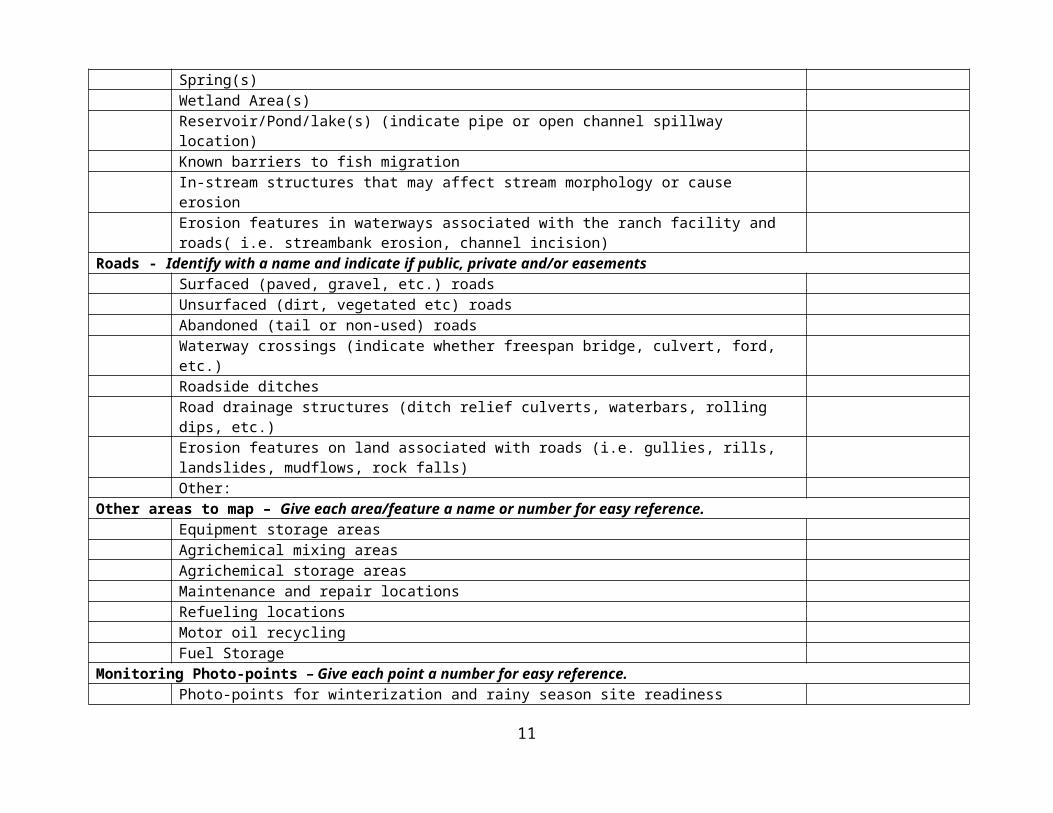
This table provides a summary of features mapped for inclusion in your Ranch Plan. Please indicate below which features are displayed on your Ranch Plan map(s) by checking the box on the left. To the extent feasible, maps and photos should be kept with the Ranch Plan. In any case, maps and photos should be readily available for reference.
Mark X if mapped
Boundaries Notes
Property & plan boundariesParcel boundariesTopography (identify area with slope <5% and areas with slope >30%Pastures with indication whether year round or seasonalAreas under consideration for future pastureNon-livestock land uses
Ranch Facilities – Give each area/feature a name or number for easy reference.Pens/Paddocks Note: Paddocks are distinguishable from pastures in that paddocks are smaller in size and are considered confinement areas with little to no vegetative cover.StallsArenasWash areasEquipment yards and/or staging areasWater/shade sources for livestock
7

Manure Storage AreasAreas for manure spreadingComposting area
Soils, Erosion Control, Management & Structures – Give each area/feature a name or number for easy reference.Soil type(s) with erosion rating(s) (map from http://websoilsurvey.nrcs.usda.gov)Drainage system (diversion ditches, storm drains, and underground outlets with inlets and outlets)Sediment/attenuation/energy dissipation basin(s)Vegetated buffer strips/filter stripsErosion features on land associated w/ the ranch facility (i.e. gullies, rills, landslides, mudflows, rock falls)Other:
Waterways – Give each area/feature a name or number for easy reference.Ephemeral Stream (those that flow only during and shortly after a storm)Seasonal/Intermittent Stream (those that flow for part of the year and generally stop flowing in the late spring) Year Round Stream (those that generally flow year round)Human-made Waterways (non-roadside ditches)Swale(s)Spring(s)Wetland Area(s)Reservoir/Pond/lake(s) (indicate pipe or open channel spillway location)Known barriers to fish migrationIn-stream structures that may affect stream morphology or cause erosionErosion features in waterways associated with the ranch facility and roads( i.e. streambank erosion, channel incision)
Roads - Identify with a name and indicate if public, private and/or easementsSurfaced (paved, gravel, etc.) roadsUnsurfaced (dirt, vegetated etc) roadsAbandoned (tail or non-used) roadsWaterway crossings (indicate whether freespan bridge, culvert, ford, etc.)Roadside ditchesRoad drainage structures (ditch relief culverts, waterbars, rolling dips, etc.)Erosion features on land associated with roads (i.e. gullies, rills, landslides, mudflows, rock falls)Other:
Other areas to map – Give each area/feature a name or number for easy reference.
8

Equipment storage areasAgrichemical mixing areasAgrichemical storage areasMaintenance and repair locationsRefueling locationsMotor oil recyclingFuel Storage
Monitoring Photo-points – Give each point a number for easy reference.Photo-points for winterization and rainy season site readiness inspectionsPhoto-points for management practice implementation and annual maintenancePhotopoints of points of dischargePhoto-points to demonstrate condition downstream of discharge pointsPhoto-points to track “areas to watch” – e.g. areas with erosion or invasive weeds that you want to track over time
9

MANURE STORAGE & NUTRIENT MANAGEMENT
Background: Although horse waste (manure, urine and soiled bedding) are organic biodegradable materials, many of their biological and chemical properties can be detrimental to fish, insects and other aquatic life if those wastes get into local waterbodies. Just as horse owners plan the input (feed) for horses, they need to plan for the output (manure). Horse facility owners should develop a waste management plan to ensure clean and safe facilities, protect creeks and ground water, reduce odors and insect breeding opportunities. Effective horse manure management helps protect water quality.
Purpose: Identify practices currently in use and that are intended for implementation to: Keep surface runoff (stormwater) away from manure storage areas; divert clean water away
from manured areas in a non-erosive manner. Keep manure storage areas away from drainages and water bodies. Keep drainage from manure from percolating down into soil- especially in areas where
groundwater protection is a priority. Cover manure. Make access to storage areas convenient, size them adequately and have a contingency plan for
when waste volume exceeds capacity.
Manure Storage Areas
M1. Do you have a manure management plan or strategy?If yes, attached plan or describe.
Yes, attach plan or describe No (Consider practices #1 and 2 listed in Table M1 below)
M2. What is the volume (cubic feet) of manure produced on site on a:Daily basis______ _________ Weekly basis:____________Monthly basis:_______________
*If you are unsure, please estimate based on the following information: The average 1,000 lb horse produces 45 lbs of manure/day, or approximately 0.75 cubic feet/day.
# of horses x 45 lbs/day/horse x 30 days/month = Pounds of manure/month# of horses x .75 cubic feet/day/horse x 30 days/month / 27 cubic feet/cubic yard = Cubic yards/month
For example: if you have 3 horses, 3 horses x 45 lbs/day/horse x 30 days/month = 4,050 lbs/month3 horses x 0.75 cubic feet/day/horse x 30 days = 67.5 cubic feet/month
10
67.5 cubic feet/month / 27 cubic feet/cubic yard = 2.5 cubic yards/month
M3. What is the volume (cubic feet) of bedding used on site on a:Daily basis_______________ Weekly basis:_______________Monthly basis:______________
** if you are unsure, please estimate based on the following information: The average bedding usage is 1 cubic foot/day/horse.
# of horses x 1 cubic foot/day/horse x 30 days/month / 27 cubic feet/cubic yard = Cubic yards/month
For example if you have 3 horses, 3 horses x 1 cubic foot/horse/day x 30 days/month = 90 cubic feet/month
90 cubic feet/month / 27 cubic feet/cubic yard = 3.33 cubic yards/monthOr, a shortcut: # of Horses x 30 cubic feet/month / 27 cubic feet/cubic yard = Cubic yards of
bedding/month
M4. What is the total volume (cubic feet) of waste generated (manure + bedding) on a:Daily basis_______________ Weekly basis:_______________Monthly basis:______________
In the scenario above the total waste generated for 3 horses is 2.5 cubic yards/month of manure+ 3.3 cubic yards/month of bedding = 5.8 cubic yards/month of waste.
M5. How often are the following cleaned:Stalls_____________________ Paddocks/corrals and/or turnouts_______________
M6. What is the capacity of your storage areas for manure and other livestock-related waste (such as bedding)? ___________cubic feet
M7. Based on the answers provided above, how many days, weeks, or months worth of manure can the storage area contain? _______________ days/weeks/months (circle one)
11
Describe as needed:
Describe as needed:

M8. Conservatively, how frequently should you empty out the storage area(s)?___________________
M9. Do you or will you use sealed containers (dumpsters or steel container /drop box) to store your manure and spent shavings (bedding) until they are hauled offsite?
Yes (Please answer A through E below) No (Skip to question M10) A. What type of containers?___________________________________________________B. What is the capacity?______________________________________________________C. How frequently are the emptied?_____________________________________________D. Who is the hauler/service provider?______________________________________________E. Is there all-weather access?
Yes No If no, describe your contingency plan for loss of access due to weather or other causes (hauler unavailable).
M10. Do you or will you stockpile manure and spent bedding in a constructed storage area (manure bunker) or in open piles on the ground?
Manure bunker
Open piles (Consider practice #1, listed in Table M1 below)
Not Applicable.
A. Are manure storage areas located on high ground, above likely flood levels?
Yes No (Consider practice #2, listed in table M1 below)
B. Describe the size (length, width, and height) and the capacity (cubic yards).Length_____ feet Width______ feet Height_____ feetCapacity______ cubic yards
C. Is the storage area covered by a roof?
Yes (answer questions a and b) No (answer questions c and d)
a. What are the dimensions?
Length_____ feet Width______ feet Height_____ feet
12
Describe as needed:

b. Does the roof drain water away from the storage area in a non-erosive manner?
Yes No (Consider practice # 3, 4 and 5 in table M1 below)
c. Is the temporary cover (tarp) available for use when the pile is saturated?
Yes No (Consider practice # 6 in table M1 below)
d. Is the storage area located on an impervious (water can’t drain through it) surface?
Yes No, answer 1 though 3 below. i. How deep is the water table under or near the pile?________________ii. What is the soil type and depth under or near the pile?_________________
iii. How will you ensure that pollutants will not leach downward into the soil and groundwater? (Consider practice # 1 in table M1 below)
D. Is the surface runoff or runoff from slopes above storage area diverted around or drained away from the storage area in a non-erosive manner? (Consider practice #5, listed in Table M1 below)
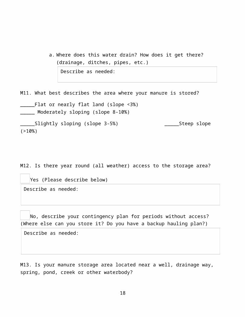
a. Where does this water drain? How does it get there? (drainage, ditches, pipes, etc.)
M11. What best describes the area where your manure is stored?
_____Flat or nearly flat land (slope <3%) _____ Moderately sloping (slope 8-10%)
_____Slightly sloping (slope 3-5%) _____Steep slope (>10%)
13
Describe as needed:
Describe as needed:
Describe as needed:

M12. Is there year round (all weather) access to the storage area?
Yes (Please describe below)
No, describe your contingency plan for periods without access? (Where else can you store it? Do you have a backup hauling plan?)
M13. Is your manure storage area located near a well, drainage way, spring, pond, creek or other waterbody?
Yes, (Please answer A through C below)
No.A. How far is the nearest waterway/waterbody? ___________feetB. Is there a vegetated (grass or other) filter strip between the storage area and the
waterway/waterbody?
Yes No (Consider practice # 7 in table M1 below)
C. Where do you take the manure/bedding when the storage area is emptied? ________
M14. Please list other manure stockpiling/storage plans or strategies not identified above.
14
Describe as needed:
Describe as needed:
Describe as needed:

Table M1: Conservation Practices for Manure Management
The following table provides an assortment of management practices that are intended to protect water quality. Implementation of all practices is not necessary or required. Selection of practices must be done on a site-specific basis and an assortment of practices to protect water quality and to suit your circumstance should be selected. NRCS Practice Titles are provided for your reference.
Practice NRCS Practice Title
Practice Implementation Date
Location (if, applicable)
1.Construct a manure bunker
2.Move manure storage areas to high ground
3. Install roof gutters Roof Runoff Structure (558)
4.Install permanent vegetation at gutter outlet to reduce erosion
Grassed Waterway (412)
5.Install rock at gutter outlet to reduce erosion Roof Runoff Structure (558
6. Cover pile with tarp when saturated
7.Plant a vegetative filter strip Filter Strip (393)
Nutrient and/or Compost Management
M15. Do you spread or plan to spread manure on site?
Yes (Please answer A through I below and consider practices # 2 and 5 listed in Table M1 below)
No
A. Will it be spread raw or will it be aged/composted?
Spread Raw (Consider Practice #3 in Table M2 below)
Aged/composted (Answer questions a and b below)
a. On-site composting takes place on a containment facility that collects any leachate.
Yes No (Consider practice # 3, listed in Table M2 below)
b. Compost is monitored to reach temperatures necessary to eliminate pathogens (131°F for a minimum of 3 days enclosed or 15 days if windrowed).
Yes No (Consider practice # 4, listed in Table M2 below)
15
Describe as needed:
Describe as needed:

B. Describe the location, frequency and method of spreading.
C. Is the manure being spread as fertilizer or soil conditioner or both?_____________________D. Will it be disked? When? During the wet season or under what conditions?
E. What equipment is available to do this work?_______________________________________
F. What type of vegetation is present where and when the manure is to be spread?
G. How many years have you been spreading manure in the same location?_______________
H. Describe your contingency plan if your storage capacity is exceeded before manure can be spread.
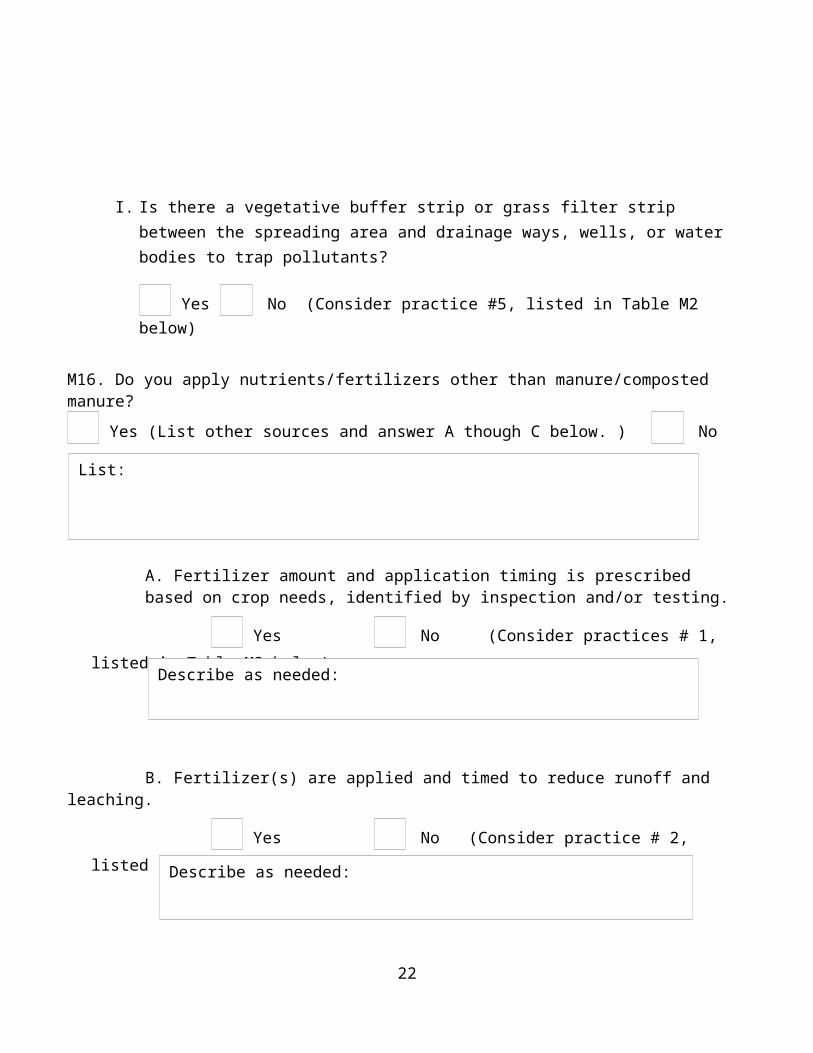
I. Is there a vegetative buffer strip or grass filter strip between the spreading area and drainage ways, wells, or water bodies to trap pollutants?
Yes No (Consider practice #5, listed in Table M2 below)
M16. Do you apply nutrients/fertilizers other than manure/composted manure?
Yes (List other sources and answer A though C below. ) No
16
List:

A. Fertilizer amount and application timing is prescribed based on crop needs, identified by inspection and/or testing.
Yes No (Consider practices # 1, listed in Table M2 below)
B. Fertilizer(s) are applied and timed to reduce runoff and leaching.
Yes No (Consider practice # 2, listed in Table M2 below)
Table M2: Conservation Practices for Nutrient and/or Compost Management
The following table provides an assortment of management practices that are intended to protect water quality. Implementation of all practices is not necessary or required. Selection of practices must be done on a site-specific basis and an assortment of practices to protect water quality and to suit your circumstance should be selected. NRCS Practice Titles are provided for your reference.
Practice NRCS Practice Title Implementation Date
Location (if, applicable)
1. Consult and follow UCCE crop requirements Nutrient Management (590)
2. Time fertilizer application to reduce runoff and leaching
Nutrient Management (590)
3.Compost animal manure on a containment facility
Composting Facility (317)
4.Monitor compost temperature Composting Facility (317)
5.Plant a vegetative filter strip Filter Strip (393)
17
Describe as needed:
Describe as needed:
PASTURE MANAGEMENT
Background: Pastures are areas where grass is grown for forage for livestock and maintained to prevent erosion and protecting a pasture's soil and vegetative cover will help to maintain pasture productivity. Soil erosion usually occurs when vegetative cover is removed and soil is left unprotected during the winter months. Soil erosion in pastures is usually the result of poor grazing management. Over stocking a pasture and allowing livestock to graze forage down to bare ground is probably the single fastest way to destroy the pasture and soil resource. Livestock can be very disruptive to soil in other ways as well. If animals are allowed to graze during periods of irrigation of heavy rainfall they can compact the soil and destroy plant cover. Livestock trails can also cause the soil to erode specially on steeper slopes where runoff water finds its way into the ruts that are formed by the animals. Areas along water courses such as streambanks are particularly susceptible to erosion caused by livestock, especially if alternate watering facilities are not adequate. Riparian areas are also prone to overuse by livestock seeking shade and riparian growth to browse on. If livestock are not well distributed over the pasture the likelihood of overgrazing and potential for soil erosion becomes greater. Other areas that have the potential for erosion include paddocks, access roads, parking areas and adjacent fields where runoff from these unprotected surfaces is increased and concentrated.
Purpose: Identify practices currently in use and that are intended for implementation to: Maintain grass cover on pastures (can be dry grass at the end of the season) to protect soil from
erosion and to maintain plant vigor. Limit livestock access to creeks and ponds when possible; provide other sources of drinking
water. Provide extra protection in riparian areas to prevent erosion and over-use. Practice rotational grazing; divide up pastures and move livestock from one to another to allow
pastures to rest and recover. Keep livestock out of the pastures during wet months or when forage is no longer available in
pastures. Develop water sources, shade structures or other attractants to attract livestock to remote
portions of pastures. Manage weeds for pasture health and animal health.
* Note: Pastures are distinguishable from "paddocks" in that paddocks are smaller in size and are considered confinement areas with little to no vegetative cover.
PM1. Do you have a dust management strategy?
Yes, describe below No (Consider practices # 1 through 4, listed in Table PM1 below)
18

PM2. Do you have a mud management strategy?
Yes, describe below No (Consider practices # 1 through 5, listed in Table PM1 below)
PM3. Does livestock graze in pastures located on your property? Yes (Please answer A below) No
A. Do you have more than one pasture? Yes (Do you practice rotational grazing?__________) No (Consider practice # 1 in Table PM1 below)
PM4. Do you board livestock that are kept in pastures full time that do not have access to stalls or a
paddock? Yes No
PM5. Does the livestock have direct, unlimited access to drainage ways, stream channels or ponds?
Yes (Consider practices # 4 through 7 in Table PM1 below) No
PM6. Is the livestock moved from the pastures when necessary to protect the pastures from erosion and damage to grass? (i.e. when the soil is saturated or when they have grazed it to 4 inches or lower.)
Yes No (Consider practices# 1 and 2 in Table PM1 below)
PM7. Please list any additional measures or practices you employ to protect your pastures from overgrazing and/or erosion?
PM8. Do you manage your pastures to limit or control weeds?
Yes No (Consider practice # 11 in Table PM1 below)
19

PM9. What type of shade is provided for livestock on pastures? How far is it located next to surface water? Is it the only shade available? (Consider practice # 3, 4 and 5 in Table PM1 below)
PM10. What water sources are provided for livestock on pastures? How far are they located from surface water? Please indicate water sources on your facility map. (Consider practices # 3, 4 and 5 in Table PM1 below)
PM11. Are pasture areas irrigated?
Yes (Consider practices # 8, 9 and 10 in Table PM1 below) No
Table PM1: Conservation Practices for Pasture Management
The following table provides an assortment of management practices that are intended to protect water quality. Implementation of all practices is not necessary or required. Selection of practices must be done on a site-specific basis and an assortment of practices to protect water quality and to suit your circumstance should be selected. NRCS Practice Titles are provided for your reference.
Practice NRCS Practice Title Practice Implementation Date
Location (if, applicable)
1. Divide pastures for rotational grazing Fence (382)
2.Provide a stable, non eroding surface for areas frequently used by animals
Heavy Use Area Protection (561)
3.Install walkways to change animal traffic patterns
Animal Trails and Walkways (575)
4.To provide access to drinking water for livestock.
Watering Facility (614)
5. Provide additional water sources to animals to improve distribution
Livestock Pipeline (516)
6.Install riparian fencing to limit animal access to waterways
Fence (382)
20

7.To provide protection against stream erosion
Riparian Forest Buffer (391)
8.Keep irrigation water use records Irrigation Water Management (449)
9.Replace leaky pipes Irrigation Water Management (449)
10.Obtain an evaluation of the existing irrigation protection system
Irrigation System Evaluation (449)
11. Consult UC Cooperative Extension Pest Management guidelines
21
STORMWATER DRAINAGE AND CONFINEMENT AREAS
Background: Rainwater flowing across the land, or in channels or pipes is called Stormwater Runoff. If stormwater runoff is allowed to erode soil from bare areas or run through manured areas, it becomes polluted and must not be allowed to enter a stream. High use areas, such as buildings, corrals, arenas, paddocks, turnout areas, manure storage areas, etc., are areas that must be managed to keep clean water from becoming polluted. Diverting fresh water around high-use areas will keep the “clean water clean” and minimize the runoff from high-use areas. By keeping the size of high-use areas small, managing polluted water can be reduced. It is much easier to manage the clean water than treat the water once it becomes polluted.
Purpose: Identify practices currently in use and that are intended for implementation to: Keep clean water clean. Do not mix with waste water or allow to run through confinement areas or manure storage
areas. Convey stormwater drainage such that erosion and soil loss are prevented
Roof Drainage* Note there are approximately 7.5 gallons of water in a cubic foot. Therefore a 100 square feet (10 foot x -10 foot) of impervious area, such as a roof, will capture, yield approximately 62.5 gallons of rainwater with each inch of rainfall. This statistic may prove helpful in evaluating your current runoff management from barn and stall roofs.
SW1. Do you have gutters and down spouts on all barn, stall and paddock roofs?
Yes No (Consider practice #1 in Table SW1 below)
SW2. Do the down spouts tie into a drainage system that keeps the clean water away from contaminants such as manure, urine or bare ground?
Yes No (Consider practices # 2 and 3, listed in Table SW1 below)
SW3. If you do not have gutters on every building, is the clean water kept out of the contaminated areas (areas with manure, urine, or bare ground)?
Yes (If so, how?) No (Consider practices # 1 and 4 listed in Table SW1 below)
Property DrainageSW4. Do you have drainage systems installed on your property?
Yes (Please indicate these systems on your site plan map) No
22
Describe as needed:

SW5. Do you have a back up plan in case of system failure? Please explain.
Yes No
SW6. Do all of the drainage systems that carry contaminated water outlet into a filter area? Please
explain.
Yes No (Consider practice #5 in Table SW1 below)
SW7. Do you combine your clean and contaminated water into the same outlet area? Please explain.
Yes No
Table SW1: Conservation Practices for Management of Stormwater DrainageThe following table provides an assortment of management practices that are intended to protect water quality. Implementation of all practices is not necessary or required. Selection of practices must be done on a site-specific basis and an assortment of practices to protect water quality and to suit your circumstance should be selected. NRCS Practice Titles are provided for your reference.
Practice NRCS Practice Title
Practice Implementation Date
Location (if, applicable)
1. Install roof gutters contaminated water
Roof Runoff Structure (558)
2.Divert downspout water away from contaminated areas
Diversion (362)
3.Tie down spouts into a drainage system
Roof Runoff Structure (558)
4.Install a roof or cover to divert clean water from animal management areas
Roof and Covers (367)
5.Plant a vegetative filter strip Filter Strip (393)
23
Describe as needed:
Describe as needed:
Describe as needed:

Confinement AreasSW8. Are livestock maintained in open air (unroofed/uncovered) areas such as paddocks, turnouts, corrals, pipe pens, arenas etc.?
Yes (Please answer A though F below, and consider practice #1 in table SW2 below)) No
A. How often are paddocks, corrals, arenas etc cleaned? ______________________________B. How are they cleaned? What equipment is used?
C. What is the approximate slope of the confinement areas?
D. Is there surface material applied to these areas? What kind in each area?
E. Is there adequate drainage in these confinement areas, or does water puddle or pond during and after storms?
Yes (Drainage is adequate) No (Consider practice # 2 in Table SW2 below)
F. Does water run through or into confinement areas from adjacent hillsides, adjacent roofs or other adjacent water sources?
Yes. (Please answer 1 through 4 below) No
1. Can this excess water be diverted away from the confinement area in a non-erosive manner?
Yes. Describe how. (Consider practices # 2 and 4 in Table SW2 below)
No
2. Describe measures to prevent puddling or ponding of water in confinement areas.
3. Does water run off the confinement area? Yes No
24
Describe as needed:

4. Does water drain to a drainage way, seasonal waterway or year round waterway?
Yes. Answer i through iii below. No
i. How far is the confinement area from the drainage way, creek stream, pond or other waterbody? Does the drainage way contain fish or other sensitive aquatic species?
ii. Is there a grass filter strip between the confinement area and drainage way to trap manure and soil particles?
Yes. Answer below and indicate on site map No (Consider practice #3 in Table SW1 below)
1. How wide is the filter strip? ___________________________2. What is the slope and vegetation condition in the filter strip?
iii. Describe measures to prevent manure and soil particles from confinement area from draining into waterways.
Table SW2: Conservation Practices for Management of Confinement AreasThe following table provides an assortment of management practices that are intended to protect water quality. Implementation of all practices is not necessary or required. Selection of practices must be done on a site-specific basis and an assortment of practices to protect water quality and to suit your circumstance should be selected. NRCS Practice Titles are provided for your reference.
Practice NRCS Practice Title Practice Implementation Date
Location (if, applicable)
1.Install a roof or cover to divert clean water from animal management areas
Roof and Covers (367)
2.Alter ground surface to improve drainage and prevent clean water from mixing with contaminated water
Diversion (362)
3.Install a vegetated filter strip Filter Strip (393)4.Install a vegetative filter waterway Grassed Waterway
(412)
25

WASH WATER
Background: Wash water is the runoff from water used to clean areas and/or structures on a ranch. Wash water can contain livestock medications, pesticides and other substance topically applied to the animals to treat hoof ailments, skin disorders, parasites, worms, etc. Runoff containing these substances should probably not be directed to a septic system, but sanitary sewers or properly-designed filter strips could help.
Purpose: Identify practices currently in use and that are intended for implementation to: Keep clean water clean Do not mix with waste water. Minimize the volume of wastewater produced. Drain waste water into septic systems, sewer systems or vegetated filter strips for treatment. Do not discharge waste water directly into storm drains, drainages, creeks, ponds, etc.
Livestock Areas
WW1: Do you have designated horse/livestock wash areas at your facility?
Yes (Indicate on your facility map and answer A though F below) No
A. Is the wash area/facility located close enough to a drainage way, creek or pond that runoff enters a waterway rather than infiltrating?
Yes (How close?_____________) (Consider practice # 1, listed in Table WW1 below)
No
B. Does the wash area have a hard surface with a drain? Yes No
C. Where does the wash water drain?
D. Is the wash water "treated" (discharged into a filter strip, settling pond, etc.) on site?
Yes. Describe below. No (Consider practice # 1, listed in Table WW1 below)
*Please make sure that the wash area, drainage and filter strips are shown on your site plan.
26
If wash water is treated in a filter strip describe the soil, slope and vegetation of the filter strip.

Stall Cleaning
WW2. Do you have indoor stalls with solid flooring, not soil or other permeable surface material?
Yes. Describe below. No
A. Do you wash out your stalls with water containing soap or other chemicals?
Yes (Consider practices # 1 and 2 listed in Table WW1 below.) No
B. How often and for what reasons is stall washing done?
C. Where does wash water drain?
D. What is the plan for treating dirty water? (Consider practices # 1 and 2 listed in Table WW1 below)
Table WW1: Conservation Practices for Management of Wash Water
The following table provides an assortment of management practices that are intended to protect water quality. Implementation of all practices is not necessary or required. Selection of practices must be done on a site-specific basis and an assortment of practices to protect water quality and to suit your circumstance should be selected. NRCS Practice Titles are provided for your reference.
Practice NRCS Practice Title Practice Implementation
Location (if, applicable)
1.Install a vegetated filter strip Filter Strip (393)2.Install a grassed waterway
Grassed Waterway (412)
27

NATURAL WATERWAYS, NON-ROADSIDE DITCHES, AND SPILLWAYS
Waterways, channels and streams, swales, ditches, and riparian areas are sensitive to agricultural, forest, and other land use activities and practices. These waterways also may act as a conduit for sediment and other pollutants. Healthy riparian zones provide a number of environmental benefits and may protect streambanks from erosion. Riparian areas also buffer waterways from the effects of potential nutrient, pesticide, pathogen and sediment runoff.
Purpose: Describe the condition of natural stream channels, riparian areas, and human-made waterways (non-roadside ditches and pond/basin spillways) on the property including the rate of bed and/or bank erosion, channel incision, head-cutting and the condition of human-made structures in the channel. Describe the conservation practices being implemented to protect waterways from water quality degradation.
W1.The waterways on the property that are on or adjacent to the ranch facility are:
All natural Mixed All non-roadside ditches and spillways No Waterways
W2. Complete this inventory of waterways on the property
Waterway Name (Labeled on Map)
Channel Top Width (ft)0-10, 11-25, 26-50, 51-100, 101-200, 200+
Channel ConditionStable, incising, head cutting, widening, aggrading/bank slough
Riparian Corridor Width0-10, 11-25, 26-50, 51-100, 101-200, 200+
Riparian CorridorMinimal, sparse vegetation, dense veg, overgrown
28

W3.Equine facilities are set back from waterways by the minimum distance required by County regulations (or greater distance).
Yes Some waterways No (Consider practice #7, listed in Table W1 below)
W4. Other activities and/or features (e.g. vegetation removal, equipment turnarounds) within County-required setbacks are in compliance with County requirements.
Managing Erosion and Water Quality in Natural Waterways
W5.Riparian Areas have vegetative cover.
All banks Some banks No Banks (Consider practices # 3 and 4, listed in Table W1 below) Not Applicable
W6.The riparian canopy along natural waterways provides shade to the waterway.
All banks Some banks No Banks (Consider practices # 1 through 4, listed in Table W1 below) Not Applicable
W7. Erosion sites along waterway banks are being treated and/or managed to restore and/or maintain natural channel function.
All banks Some banks No Banks (Consider practices # 1 though 5, listed in Table W1 below) Not Applicable
29
Describe as needed:
Describe as needed:
Describe as needed:
Describe as needed:
Describe as needed:

W8.Agricultural supplies (heaters, trellis parts, irrigation supplies, machinery, etc.) are stored outside of the required waterway setback during winter months.
All supplies Some supplies No supplies (Consider practice #7, listed in Table W1 below)
Table W1: Conservation Practices to Reduce Erosion in Natural Waterways
The following table provides an assortment of management practices that are intended to protect water quality. Implementation of all practices is not necessary or required. Selection of practices must be done on a site-specific basis and an assortment of practices to protect water quality and to suit your circumstance should be selected. NRCS Practice Titles are provided for your reference.
Practice NRCS Practice Title Implementation Date
Location (if, applicable)
1.Consult a Professional Streambank Protection (580)
2.Establish new riparian plantings Irrigation System, Sprinkler (442)
3.Remove invasive riparian plants Restoration & Management of Declining Habitats (643)
4.Establish native riparian trees and shrubs
Riparian Forest Buffer (391)
5.Establish native riparian grasses and forbs
Riparian Herbaceous Cover (390)
6.Install a rock lined basin to dissipate hydraulic energy
Structure for Water Control (587)
7.Provide more space to the stream by setting back structures7.Establish an agricultural supply yard away from the waterwayOther:
30
Describe as needed:

Enhancing Native Vegetation, Fish and Wildlife Habitat in Natural Waterways and Riparian Areas (Optional)
W9.Riparian areas have a variety of native vegetation that includes grasses, forbs, trees and shrubs.
All banks Some banks No banks (Consider practices # 3 and 4, listed in Table W2 below) Not Applicable
W10.Riparian areas have non-native/invasive plants.
All banks (Consider practices # 1 through 4, listed in Table W2 below) Some banks No Banks Not Applicable
W11. There are structures within waterways known or suspected to cause obstruction to fish passage.
Yes (Consider practices # 1 and 5, listed in Table W2 below) No Not Applicable
W12. There is habitat complexity with the stream channel, including deep pools that stay wet even if/when the rest of the stream channel is dry and structures such as wood, boulders, and over-hanging roots that slow down fast-moving water in high flows and provide shelter in pools when flows are lower.
All waterways Some waterways No waterways (Consider practices # 1 and 6, listed in Table W2 below) Not Applicable
31
Describe as needed:
Describe as needed:
Describe:
Describe as needed:

Table W2: Conservation Practices to Enhance Native Vegetation, Fish and Wildlife Habitat in Natural Waterways and Riparian Areas
The following table provides an assortment of management practices that are intended to enhance waterways and riparian areas. Implementation of all practices is not necessary or required. Selection of practices must be done on a site-specific basis and an assortment of practices to protect water quality and to suit your circumstance should be selected. NRCS Practice Titles are provided for your reference.
Practice NRCS Practice Title Implementation Date
Location (if, applicable)
1.Consult a Professional2.Remove invasive riparian plants Restoration &
Management of Declining Habitats (643)
3.Establish native riparian trees and shrubs Riparian Forest Buffer (391)
4.Establish native riparian grasses and forbs Riparian Herbaceous Cover (390)
5.Modify instream structures to improve fish passage
Stream Habitat Improvement and Management (395)
6. Install in-stream structures to enhance habitat
Stream Habitat Improvement and Management (395)
7.Provide more space to the stream by setting back vinesOther:
Managing Erosion and Water Quality in Non-Roadside Ditches
W13.Ditch beds are stable (not sloughing, downcutting, nor eroding).
All banks Some banks No Banks (Consider practices # 1 through 6, listed in Table W3 below) Not Applicable
32
Describe as needed:

Table W3: Conservation Practices to Reduce Erosion and Manage Stability and Conveyance in Non-Roadside Ditches
The following table provides an assortment of management practices that are intended to protect water quality. Implementation of all practices is not necessary or required. Selection of practices must be done on a site-specific basis and an assortment of practices to protect water quality and to suit your circumstance should be selected. NRCS Practice Titles are provided for your reference.
Practice NRCS Practice Title
Implementation Date
Location (if, applicable)
1.Consult a Professional2.Establish native grasses and forbs Riparian
Herbaceous Cover (390)
3.Line an eroding swale or diversion ditch Lined waterway or outlet
4.Install rock check structures to dissipate hydraulic energy
Structure for Water Control
5.Plant a vegetative filter waterway Grassed Waterway
Other:
Managing Erosion from On-Farm Pond/Basin Spillways
W14.There is an on-farm pond or basin (including sediment and attenuation basins) on the ranch facility.
Yes No
W15.Open channel spillways are stable (not eroding) and/or properly armored to prevent erosion.
All Spillways Some spillways No spillways (Consider practices # 1 through 5, listed in Table W4 below) Not Applicable, all spillways are piped
33
Describe as needed:
Describe as needed:

W16. Piped and open channel spillways from on-farm ponds contain pond overflows.
All Spillways Some spillways No spillways (Consider practices # 6 and 7, listed in Table W4 below)
Not Applicable, all spillways are open channels.
W17.The alignments of spillway outlets, both piped and open channel, are in line with the downstream waterway.
All Spillways Some spillways No spillways (Consider practice # 8, listed in Table W4 below) Not Applicable
W18. Spillways, pipe and open channel, from on-farm ponds have energy dissipaters prior to re-entering the downstream waterway.
All Spillways
Some spillways
No spillways (Consider practices # 5 and 6, listed in Table W4 below)
Not Applicable
34
Describe as needed:
Describe as needed:
Describe as needed:

Table W4: Conservation Practices to Manage Spillways
The following table provides an assortment of management practices that are intended to protect water quality. Implementation of all practices is not necessary or required. Selection of practices must be done on a site-specific basis and an assortment of practices to protect water quality and to suit your circumstance should be selected. NRCS Practice Titles are provided for your reference.
Practice NRCS Practice Title
Implementation Date
Location (if, applicable)
1.Consult a Professional2.Install a rock weir to control in-channel flow Grad
Stabilization Structure (410)
3.Widen/enlarge the spillway Pond4.Stabilize the open channel spillway Pond
5.Plant a vegetative filter waterway Grassed Waterway (412)
6.Install a rock lined plunge basin Structure for Water Control (587)
7.Install bank protection at the spillway outlet Streambank Protection (580)
8.Realign the existing spillway with the downstream waterway
Pond
Other:
35

ROADS AND CROSSINGS (IF APPLICABLE)
Background: Roads that drain toward waterways can be major contributors of sediment. Roads must be safe to travel while having a minimal effect on waterways in the watershed. Practices to address erosion from roads aim to reduce the concentration of flow from roads, slowing the rate of water running off of the land and discharging accumulated waters more frequently to areas away from waterways.
Purpose: To identify practices currently in use and intended for implementation to slow, spread and sink runoff from the roads with slopes of 5% and greater. Identify priority road reaches that may discharge directly to waterways (hydrologically connected) so that no more than 25% of roads are connected in 20 years.
ROADS ON THE PROPERTY
R1.Roads on the property cross waterways.
Yes (Please complete the Road Stream Crossing Data Form that follows. Please make a copy of the data form for each crossing.)
No (Skip this section)
36

DATA FORM R1. ROAD STREAM CROSSING DATA FORM
Complete this data form for each place that roads cross a waterway. Make a copy of the form, including treatment options if applicable, for each crossing.
ROAD STREAM CROSSING DATA FORM (2014)
GENERALSite #:
Mapped (Y/N):
Road ID/Name: Landowner: Date: Site located up-stream of pond/reservoir (Y,N):
CROSSING TYPE
Bridge(if so then go to Bridge, Arch, Box info section)
Bottomless Arch(if so then go to Bridge, Arch, Box info section)
Box culvert(if so then go to Bridge, Arch, Box info section)
Culvert(if so then go to Culvert info section)
Oval culvert(if so then go to Culvert info section)
Ford(if so than go to Ford or Armored Fill
info section)
Armored Fill(if so than go to Ford or Armored Fill info
section)Fill
(if so then go to Fill or Pulled info section)
Pulled crossing(if so then go to Fill or Pulled info section)
Photos taken (Y, N):
Bridge, Arch, Box
info:
Bridge/Arch/Box/ height (ft):
Bridge/Arch/Box/ width (ft):
Wing walls (900&150, 300-750, 0 extension up ch.)
Culvert info
Circular culvert diam (in):
Oval culvert height (in):
Oval culvert width (in):
Culvert type
(P, S, A, C):
Trash rack type (none, SP, MP, Screen ):
If none or Screen see treatment options A9, A10.
Headwall height (ft):
Rust/silt line at inlet (in):If greater than 50% of diameter see treatment options A2, A6.
Culvert grade (% ):
If significantly shallower then stream grade see treatment option A6.
Inlet (O, C, P, R):
If C, P, or R see treatment options A1, A5, A6.
37

Plug potential (H, M, L)
If M or H see treatment options A1, A5, A6.
Interior (O, C, R, or S):If C, R, or S see treatment options A1, A5, A6.
Are fill slopes actively eroding (Y, N):
If yes see treatment option A11, A13, A14.
Outlet (O, C, P, R):
If C, or R see treatment options A1, A5, A6
Does the stream channel below outlet appear to be scoured (Y, N):
If yes see treatment option A12.
Is culvert in line with stream channel (Y, N): If no see treatment option A6.
Diversion potential (Y, N, Critical dip present):
If yes see treatment options A7, A8.
Ford or Armored Fill info
Is crossing dipped wide enough to keep flows within natural stream channel (Y, N):If no see treatment option A1
At Armored Fill crossing is armor adequate enough to prevent fill material from eroding (Y, N):
If no see treatment option A11.Fill or Pulled Crossing info
Does crossing look to be actively eroding (Y, N):
If yes see treatment options A1, A2, A3, A4, A6.
STREAM INFO
Avg. stream grade (% ): Avg. stream channel width (ft):
Average steam channel depth (ft):
ROAD DRAINAG
E TO STREAM
CROSSING
Left road length(s) draining down to site (ft): If greater than 150ft see Contributing road Length Treatments section
Avg. width (ft): Road Surface ( paved, rocked, native):
Road use (Year round, Dry weather, No recent use):
Right road length(s) draining down to site (ft):If greater than 150ft see Contributing road Length Treatments section
Avg. width (ft): Road Surface ( native , rocked, paved):
Road use (Year round, Seasonal, No recent use):
COMMENT ON STREAM CROSING AND ASSOCIATED ROAD LENGTH(S):
COMMENT ON OTHER ROAD RELATED ISSUES THAT YOU WOULD LIKE ADDRESSED:
38

ROAD STREAM CROSSING DATA FORM INSTRUCTIONS AND DEFINITIONS
GENERAL Site#: Please assign a number to each siteSites are defined as features that may deliver sediment to a stream channel. A Stream crossing (or crossing) is where a road crosses a natural drainage channel or unchanneled swale. In this data form the term site refers to a stream crossing or crossing.
Mapped: has the site location been identified on a map? (Yes or No):
Road ID/Name: give each road on the property an individual name or numeric identifier so that sites can be grouped for future treatment.
Landowner: give the name of the landowner or public agency so that sites can be grouped for future treatment.
Date: Record the date that this site was assessed (mm/dd/yy).
Site located up-stream of a pond/reservoir: is the site located on a stream channel that drains down into a pond or reservoir (Yes, No)
CROSSING TYPE Please circle the type of crossing at the site. If there are different types of drainage features at a crossing then check each. Definitions of each crossing type follow.
Bridge is a bottomless structure that has abutments built on both of the stream banks or uses the natural stream banks as abutments.
Bottomless Arch culvert is a bottomless structure that has abutments built down by the active stream cannel. The difference of this structure from a bridge is that it is usually a continuous arch from the active channel up to its apex.
Box culvert functions much like a bridge except that it has a bottom built into it. Most box culverts do not have abutments associated with them. They are usually placed in the stream channel and have fill material compacted around them.
39

Culvert is a circular pipe or structure that is placed in the stream channel to convey flows under fill material that is compacted around it.
Oval culvert is the same as above but is an oval shape.
Ford crossing (wet crossing) is designed so that the vehicle travels across the stream bed. No fill or armor material is placed in the stream bed to accommodate the crossing.
Armored fill usually constructed on streams with high stream banks that would require the excavation of substantial ramps to get vehicles down to the streambed. An armored fill crossing (wet crossing) is designed so that the stream flow travels across the road prism but the road fill is armored with rock, concrete or other hardened materials so that the fill material cannot be eroded by the stream flows.
Fill crossing (wet crossing) is a stream crossing where the road crosses a stream and no drainage structure has been constructed. This definition may also apply to stream crossings that have drainage structures but they have failed or washed out to the point that the drainage structure is no longer functioning. These crossing types are assumed to be actively eroding.
Pulled crossing is a stream crossing that has been decommissioned in the past. Decommissioned stream crossings are crossings whose drainage structure and fill materials have been excavated (pulled) from the stream channel, allowing for the stream to flow through the area as it had before the road was constructed. These crossings may need to be evaluated to determine if adverse ‘adjustments’ are occurring at the site and further treatment would be needed to reduce sediment delivery.
Photos taken (Y, N): photos can be very helpful in describing current conditions of a site and can also be used to document changes over time. It is usually helpful if there is a photo of the up-stream and down-stream sides of the crossing as well as the road approaches to the crossing. There is a section in the LandSmart plan that allows for photo descriptions. Descriptions should include what is in the photo (ex. inlet, outlet, left road, right road, etc.) and at what location the photo was taken (ex. up-stream of the inlet, on right bank, in center of crossing on the road, etc.). The use of a GPS or marking on a map the locations of the photo points can help in re-occupying these locations.
BRIDGE, ARCH, BOX INFOBridge/Arch/Box/ height (ft): is a measurement in feet from the stream channel to the bottom of the structure. If the structure is an arch then give the maximum height. The purpose of this measurement is to determine capacity of the crossing.
Bridge/Arch/Box/ width (ft): is a measurement in feet of the width of void space of the structure,
40

usually the side walls or the abutments. If the abutments are sloping then give the average width. If the crossing is an arch then give the max width. The purpose of this measurement is to determine capacity of the crossing.
Wing walls (90°&15°, 30°-75°, 0 extension up channel): some of these stream crossings may have concrete or rock walls projecting beyond the inlet. How these walls are constructed influence the capacity of the stream crossing. The angle of the wall you are asked to describe are relative to stream flow. So a 90° wall would be perpendicular to stream flow and a 0° wall would be parallel.
CULVERT INFOCircular culvert diameter: is measured in inches. Circular culverts usually come in sizes of 6” increments. The diameter should be given as it was constructed and not the diameter relative to how crushed or buried it may be. If there are multiple culverts at the crossing give the diameter of each.
Oval culvert height: is measured in inches. Give the maximum height as the culvert was constructed and not relative to how crushed or buried it may be. If there are multiple culverts at the crossing give the height of each.
Oval culvert width: is measured in inches. Give the maximum width as the culvert was constructed and not relative to how crushed or buried it may be. If there are multiple culverts at the crossing give the width of each.
Culvert type: give the type of material the culvert is made of; plastic, steel, aluminum, or concrete. If there are multiple types of culverts at the site then check each type.
Trash rack type: (none present, single post, multiple post, screen). A trash rack is placed above the inlet of the culvert and is used to reduce plugging of the culvert by debris. Also see plug potential below.
Headwall height: is given in vertical feet, to the nearest ½ foot increment. The headwall height is measured from the bottom of the culvert inlet/stream bed to the location where, if the crossing were to flood, the flow would exit into the inboard ditch or onto the road surface. This location may or may not be directly above the culvert inlet, this is dependent on how the road travels through the crossing. This measurement can be achieved by using a measuring tape and clinometer. Take the slope angle (degrees) and the length (feet).
Slope sin(length) = vertical height
Rust or silt line at inlet: The height of the rust/silt line at the inlet gives an indication of the average flow depth that the crossing receives. A rust/silt line greater than 50% of the diameter of the culvert
41

may be an indicator that the crossing is undersized. Though rust/silt line height may also be a result of how shallow the culvert is relative to stream channel grade.
Culvert grade: measured in percent grade. Use a hand held clinometer and look through the inlet or outlet of the culvert to determine its grade. The reason for collecting this data is to see if the culvert is significantly shallower than the stream grade. Culverts that are significantly shallower tend to have greater plug potential.
Inlet: is it open, crushed, plugged and/or rusted? For the inlet to be defined as crushed or plugged it should be greater than 20%. For the inlet to be defined as rusted you should observe rust holes through the culvert.
Plug potential: at the inlet. Culverted stream crossings tend to have a higher plug potential than other sites because their void space is usually narrower than the stream channel. Another way to think of a culverted stream crossing is as an ‘earthen dam with a hole at the bottom’. It is important to remember that stream channels do not just transport water but also carry woody debris and sediments. Some of the factors to consider when determining plug potential are:
1) Setting. Is the crossing in a forested, chaparral, or grassland setting? The more woody material in the stream channel above the crossing the greater the plug potential.
2) Culvert grade relative to stream grade. The shallower the culvert grade is relative to stream grade the more likely woody debris and sediments are to settle out at the inlet.
3) Trash rack at inlet. If there is no trash rack above the inlet and the culvert diameter is smaller than the stream channel width you have an increased likelihood of plugging. A single post trash rack above the inlet can greatly reduce the likelihood of woody material plugging the inlet of a culvert. Multiple posts above the inlet can also reduce plug potential but they may also initiate scour around the outer posts as material collects along the posts. Having a screen across the inlet of your culvert can actually increase plug potential because you are preventing any material to pass through the culvert.
Interior: is it open, crushed, plugged, rusted, and/or separated? For the interior to be defined as crushed or plugged it should be greater than 20%. For the interior to be defined as rusted you should observe rust holes through the culvert bottom. Separation: culverts usually come in 20’ lengths, over time these sections can become uncoupled and allow flow to exit the culvert. If the interior of the culvert cannot be observed from either the inlet or outlet due to the condition of either of these locations than assume the same condition for the interior as either of the openings.
Are fill slopes actively eroding: Yes or No. Based upon observations of the fill slopes around the culvert inlet and outlet are they:
42

1) Showing signs of rilling or Gullying?2) Do you see tension cracks or slumps?
3) Or are the fillslopes well protected with vegetation, rock armor, concrete or other hardscape?
Outlet: is it open, crushed, plugged and/or rusted? For the outlet to be defined as crushed or plugged it should be greater than 20%. For the outlet to be defined as rusted you should observe rust holes through the culvert.
Does the stream channel below outlet appear to be scoured: Yes or No. This is usually the case when the outlet of the culvert is a substantial vertical distance above the stream channel, often referred to as ‘shot-gunned’. When the culvert outlet is shot-gunned the water coming out of it can scour out the channel below and cause the surrounding stream banks to fail.
Is culvert in line with stream channel: Yes or No. above inlet does the stream have to make a sharp turn to enter the culvert? Is the outlet pointed at either of the stream banks? These situations will help you to determine whether or not the culvert is aligned with the stream channel.
Diversion potential: Yes, No or Critical dip present.Usually only exists at culverted stream crossings. You would answer Yes there is diversion potential if the crossing floods at the inlet, water would flow down the road or inboard ditch beyond the stream crossing’s hinge line, even if it would re-enter the same natural stream channel at some distance downslope. You would answer there is No diversion potential if the water would flow straight across the road and spill back into the same stream channel. The presence of a critical dip to reduce diversion potential would allow you to answer No to diversion potential. See section of ‘Road lengths draining down to site for further check.
STREAM INFOAverage stream grade: is given in % slope and is an average of the overall grade. Enter the average slope of the stream channel upstream from the site beyond any aggraded sediments that may exist near the inlet of the crossing.
Average stream channel width (ft): is given in feet. This measurement is achieved by walking up-channel from the stream crossing, beyond any aggraded sediments. The average width is determined by measuring the channel bottom width, the top of bank width and dividing by 2 (W1+W2/2). In smaller stream channels there may be only one width observable.
Average stream channel depth (ft): is given in feet. This measurement is calculated at the same location as the previous section. Measure the height from the channel bottom to the top of bank (bank full).
ROAD DRAINAGE TO STREAM CROSSING
43

If you are using a map that can be written on it may be helpful to map all road/avenue lengths draining down to each site. This can be done by using a bracket ( [ ]) symbol to indicate start of road length with an arrow symbol ( → ) pointing toward the site. Ex. [→ → site# ← ←]
Road lengths draining down to the site: Standing on the road surface, above the stream crossing and looking down stream, record the total distance of road length(s) draining down to the site. Left road length and Right road length are relative to looking down stream. Include road intersections and spur road lengths. If the road continues downhill through the site then cut-off your road length at the site and count the road length draining away as 0ft. Road surface drainage features that effectively end the road length include functional waterbars, rolling dips, and natural drainage break (divides and dips). If a culverted stream crossing has 0 Left or Right road length s draining to the site then the crossing has Diversion potential.
Average width: of the road length(s) draining down to the site, measured in feet. Take a represented measurement of the width of the road from the cutbank to the outside edge of the road prism.
Road surface: Paved roads have either asphalt or concrete surface and is adequately covered to protect against rain-drop impact and allows for wet-season use. Rocked roads/avenues have a surface that is adequately covered with road-base rock to protect against rain-drop impact and allows wet-season use. Grassed avenues are adequately covered (during rainy season) with vegetation to protect against rain drop impact. Native roads/avenues are unsurfaced or dirt, with minimal vegetative cover, even though they may contain some natural rock.
Road use: Year round use means roads/avenues are driven when they are wet. Dry weather use means the roads/avenues are not driven when they are wet. Turn around use means that the avenue is not driven but rather used as a tractor turn around between vine rows. No recent use is for roads that have not been driven in at least the past 5 years.
COMMENTS ON PROBLEMThis is an optional field. This section is available for you to describe in more detail characteristics of the site that may or may not have been covered earlier in the data form. The summary comments for each site generally describe the nature of the erosion problem as well as other important site characteristics. Remember there is a real difference between the cause and the symptom of many erosion problems. Wherever feasible, it is important to treat the cause of the problem rather than the symptom. You may want to refer to specific photos of the site in this section as well. A discussion on the historical maintenance needs of the site may help in determining treatment options and prioritization.
COMMENTS ON OTHER ROAD RELATED ISSUES
44

This is an optional field. This section is available for you to describe other road related issues that you have been experiencing but were not covered in this data form. These issues may be transportation concerns or chronic maintenance site that may or may not have impacts to water quality.
RCD use only
Fish barrier (NA, N, P, D):
Q: Undersized (Y, N, Site requires further engineering to determine capacity):
Recommended size:
Site requires further engineering to determine capacity and or fish passage.
Total chronic erosion vol. (yds3):
Eposodic future volume (yds3):
Episodic Erosion Potential (H, M, L)
Total future erosion vol. (yds3):
Treat Priority. (H, M, L, No treat):
ASAP (Y, N):Upgrade Decommission
RCD Use Only Instruction and Definitions
Fish barrier if anadromy is known or likely on the section of the stream that the site is located then a fisheries biologist should be consulted to determine if the crossing is a barrier to fish passage. Non-applicable would be selected to identify that the site is not located on an anadromous stream. No means that the structure does not inhibit fish passage for all life stages of anadromous fish species. Partial means a barrier to anadromous fish species at some or all life stages or at certain flow events. Definite means a complete barrier to anadromous fish migration.
Q is the discharge at the stream crossing for a given storm event. This value can be derived by using a variety of methods such as the Rational Method or USGS Regional Regression Equations.
Undersized once you have determined the discharge at the site you can now look at the existing capacity of the crossing and determine if it is undersized. Answer Yes, No or need further engineering. Stream crossings draining larger watershed areas may require engineering beyond the abilities of the RCD to determine the best design. See Cost effectiveness in Treatment priority section.
45

Recommended size if the crossing is undersized then based upon the discharge of the site what is the recommended size or void space to adequately drain the stream.
Site requires further engineering for fish passage design. Stream crossings draining larger watershed areas or that are along anadromous stretches of streams may require engineering beyond the abilities of the RCD to determine the best design. See Cost effectiveness in Treatment priority section.
Chronic erosion volume is measured in cubic yard on either an annual or decadal timeline. Chronic erosion is sediment production from road surfaces and cutbanks during storm events that produce runoff. This erosional process is termed chronic because it occurs annually. Chronic erosion is calculated by taking the road length and multiplying that by a width and surface lowering rate. This erosion will occur through a combination of:
1) Cutbank erosion (i.e., dry ravel, rainfall, freeze-thaw processes, cutbank failures). 2) Inboard ditch erosion and sediment transport.3) Mechanical pulverizing and wearing down of unpaved road surface.4) Erosion of unpaved road surface if driven during wet weather periods.
Episodic erosion volume is measured in cubic yards. Stream crossing wash-out is termed episodic because it occurs in response to storm events or other triggers. This erosion may occur once, or in pulses over an indeterminate time period. The volume of fill material with the stream crossing will need to be determined by doing a volume calculation. The fill volume within the stream crossing is always assumed to be 100% delivery to the stream system.
If a stream crossing is identified as being adequately sized and looked to be structurally intact, then it is considered ‘storm-proofed’. Therefore no future episodic erosion volume will be assigned to that site.
Stream crossings with diversion potential make it difficult to accurately determine episodic erosion volume. When this occurs the roadbed, hillslope, and/or stream channel that receive the diverted flow may become deeply gullied or destabilized. Road and hillslope gullies can develop and enlarge quickly and deliver large quantities of sediment to stream channels. Stream flow that is diverted onto steep unstable slopes may also trigger hillslope landslides and large debris flows. Because of the variability of erosion that can occur due to diverted stream flows it is difficult to accurately determine the future erosion volume at these sites. For the purpose of this data form, the episodic erosion volume at stream crossings with diversion potential will be quantified the same way as stream crossings without diversion potential.
Episodic erosion potential only applies to the episodic erosion volume because the chronic erosion volume is assumed to be occurring annually. Episodic erosion potential is a qualitative evaluation of the likelihood of the stream crossing to wash-out, during a given storm event(s), based on surficial
46

observations. It is a subjective probability estimate, expressed as “low,” “moderate,” or “high,” and not an estimate of how much erosion is likely to occur. More than one erosional process may be occurring at a site, therefore the erosion potential should reflect the most important erosional feature or mechanism. Factors to observe in determining erosion potential are:
1) Gullying or eroding fillslopes.2) Tension cracks or slumps observed on the fillslopes or road surface.3) Are the fillslopes well protected with rock armor, concrete or other hardscape?4) How undersized a crossing is for a given storm event. 5) At culverted crossings, how significantly; crushed, plugged, separated, or rusted through is the culvert.6) Erosion potential is also a function of stream power relative to the amount of fill in the stream crossing. But
don’t underestimate stream power for large storm events.7) Road use. If the road is unused then it is assumed that erosional processes are occurring
unchecked. Therefore given enough time, even low erosion potential factors can completely wash-out a stream crossing.
Total future erosion volume is the sum of the episodic and chronic erosion volumes for each site.
Treatment priority is a professional evaluation of how important it is to quickly perform erosion control or erosion prevention work at a site. It is an integral part of an assessment because it is the basis for prioritizing treatment sites prior to implementation. Treatment priority is designated as “high,” “moderate,” or “low,” indicating the relative degree of urgency to treat the site before it erodes or fails. Sites that require further engineering to determine capacity will not be given a treatment priority until such work has been done. Criteria for evaluating treatment priority include:
1) Erosion potential, or whether there is a low, moderate, or high likelihood for future episodic erosion at a site. Remember that only the episodic erosion volume has an erosion potential whereas the chronic erosion volume is assumed to be occurring on an annual basis.
2) Sediment delivery volume, which is an estimate of the sediment volume projected to be eroded from the site and the associated road lengths. It is entirely possible to have large episodic erosion volumes but because it has a low erosion potential, the site may be classified with a low (L), moderate-low (ML) or moderate (M) treatment priority.
3) Diversion potential at culverted stream crossings. These sites should be given a higher treatment priority than sites with similar characteristics but without diversion potential.
4) Stream crossing capacity, weather it us undersized or not for a given storm event (example the 100-year peak storm flow). This should be looked at on a magnitude basis, i.e. ‘how much is the crossing undersized for a given storm event. Crossing sizing not only determines its capacity to carry water during peak flows but also influences plug potential.
5) Evaluation of the sites for fish passage on anadromous streams. If the site poses a barrier to salmonid fish migration then the site should receive a “High” treatment priority regardless of its
47

erosion volume or potential. Also take into consideration the amount and quality of habitat that would be made available.
6) The value or sensitivity of downstream resources being protected. In general, all sites located up stream of an instream pond or reservoir are identified as ‘disconnected’ and should be given a Low treatment priority. These sites are deemed ‘disconnected’ from the anadromous portions of the watershed because these instream structures act as sediment basins for upstream erosional process and are barriers to anadromous fish species.
7) Cost effectiveness may be analyzed, along with transportation needs, to prioritize treatment sites or locations for implementation. Cost effectiveness is not only a necessary consideration for environmental protection and restoration projects for which funding may be limited, but is also an accepted and well-documented tool for prioritizing potential treatment sites in an area. A quantitative estimate for cost effectiveness is determined by dividing the cost of accessing and treating a site by the volume of sediment prevented from being delivered to local stream channels (the sediment savings). The resulting value provides a comparison of cost-effectiveness among sites, and an average for the entire project area. For example, if the cost to develop access and treat an eroding stream crossing is projected to be $5,000, and the treatment will potentially prevent 500 yd3 of sediment from reaching the stream channel, the predicted cost effectiveness for that site would be $5,000/500yd3, or $10/yd3. At sites that pose barriers to anadromous fish passage, cost effectiveness could be looked at from the standpoint of amount and quality of upstream habitats that would be made available to the species.
ASAP treat as soon as possible (Yes or NO). This would exceed a ‘High’ treatment priority and would suggest an emergency fix.
Upgrade would indicate that the treatment recommended for storm proofing would incorporate continued vehicle use and maintenance of drainage features.
Decommission could be a suggestion made if the landowner indicated that the road had not been used in the last 5 years. This would indicate that the treatment recommended for storm proofing would incorporate the idea of long term winterization where vehicles would no longer travel these sections. Road decommissioning is a cost effective way to storm proof a road because it does not require regular maintenance of drainage features. It should be noted that road decommissioning, like road upgrading, does require monitoring for the first couple of years and after large storm events to ensure no significant adjustments have occurred in the treatment areas. Road decommissioning should not be thought of a permanent closure because the road prism still exists and the stream crossings could have new drainage features installed if the road were needed again. See typical drawing 14.
48

Table R1: Treatment Options to Reduce Erosion and Manage Stability at Stream CrossingsThe following table provides an assortment of treatment options that are intended to protect water quality. Implementation of all options is not necessary or required. Selection of options must be done on a site-specific basis and an assortment of practices to protect water quality and to suit your circumstance should be selected. NRCS Practice Titles are provided for your reference and you may contact your local NRCS or RCD field office for technical assistance.
Practices
(at stream crossing)
NRCS Practice Title
Implementation Date
Location
Site#
1. No treatment at site -- --
2. Consult a Professional
3. Excavate soil Earthfill (903)
4. Install bridge Stream Crossing (578)
5. Construct Armored-fill crossing
(See typical drawings 5a, 5b, 6, 7)
Stream Crossing (578)
6. Construct a Ford crossing
(See typical drawing 5a)
Stream Crossing (578)
7. Repair culvert Access Road (560)
8. Install or replace culvert
(See typical drawing 2, 4)
Access Road (560)
9. Construct critical dip
(See typical drawing 1c)
Access Road (560)
10. Install critical culvert Access Road (560)
11. Remove screen from culvert inlet Access Road (560)
12. Install trash rack (SB, GP, I-B)
(See typical drawing 3)
Access Road (560)
49

13. Armor fill face
(See typical drawing 1b, 4)
Lined Waterway or Outlet (468) and Rock Riprap (907)
14. Armor below outlet
(See typical drawing 1b)
Lined Waterway or Outlet (468) and Rock Riprap (907)
15. Other
COMMENT ON TREATMENT(S):
50

Table R2: Treatment Options to Reduce Erosion and Manage Stability at Contributing Road Lengths
The following table provides an assortment of treatment options that are intended to protect water quality. Implementation of all options is not necessary or required. Selection of options must be done on a site-specific basis and an assortment of practices to protect water quality and to suit your circumstance should be selected. NRCS Practice Titles are provided for your reference and you may contact your local NRCS or RCD field office for technical assistance.
Practices(along road lengths)
NRCS Practice Title Implementation Date
LocationSite#
1. No treatment at site -- --2.Consult a Professional3. Construct rolling dips (See typical drawings 10, 11, 19a-c.)
Access Road (560)
4. Install Speed bumps on paved road Access Road (560)5. Outslope road & remove ditch
(See typical drawings 9a-c)Access Road (560)
6. Outslope road & retain ditch – ensure that outlet is located in a stable location
(See typical drawings 9a-c)
Access Road (560)
7. Inslope road – ensure that ditch outlets to a stable location
(See typical drawings 9a-c)
Access Road (560)
8. Crown road(See typical drawings 9a-c)
Access Road (560)
9. Install/Replace ditch relief culvert – ensure that outlet is located in a stable location
(See typical drawing 8)
Access Road (560)
10. Cut/clean ditch Diversion (362) and Access Road (560)
11. Rock armor ditch – ensure that ditch outlets to a stable location
Lined Waterway or Outlet (468)
12. Construct Water bars(See typical drawing 20)
Access Road (560)
13. Construct cross road drains(See typical drawing 17)
Access Road (560)
14. De-compact road surface(See typical drawing 17)
Road/Trail/Landing Closure and Treatment (654)
15. Other
51

AGRICHEMICALS (IF APPLICABLE)
Background: Agrichemicals (organic and/or synthetic nutrients and/or pesticides, including herbicides and sulfur) that move from the site of application into surface water can affect water quality by negatively impacting human, animal and/or non-target organism health. Nutrient sources associated with agricultural production practices may include organic and inorganic fertilizers, biodegraded crop residues, and agricultural wastes (grape pomace and waste directly generated by animals). Wind and water erosion of soil or aerial drift from agrichemical applications may contribute to pesticide movement away from the target area. Agrichemcials may enter surface waters during overland runoff and tile drainage either as water-soluble residuals or adsorbed to sediments. Nutrients from these sources become pollutants when they are transported off-site into nearby streams and lakes or percolate in excessive amounts of groundwater. Nitrates and phosphates in surface water bodies contribute to eutrophication, the increases in aquatic plants and algal blooms that deplete dissolved oxygen, impacting aquatic organisms. All shall be maintained free of toxic and biostimulatory substances in lethal or detrimental concentrations.
Purpose: To identify practices, currently in use or intended for implementation, ensure agrichemicals (fertilizers, soil nutrients, compost and pesticides) are stored, mixed and applied in a manner consistent with all applicable regulations, including those required by the California Department of Pesticide Regulation (DPR) and the County Agricultural Commissioner, and in a manner that prevents excess agrichemicals from reaching surface and groundwater.
A1. Agrichemicals are stored properly (per the label) on-site.
Yes No (Consider practice # 1, listed in Table A1 below) No- agrichemicals are stored on-site. Skip this section.
A2. Agrichemical mixing, loading, and rinsing are conducted on a containment facility.
Yes No (Consider practices # 2 through 5, listed in Table A1 below) No mixing, loading, or rinsing on-site.
52
Describe as needed:
Describe as needed:

A3. Agrichemicals not handled on a containment facility are mixed, loaded and rinsed away from aquatic habitat and wells.
Yes No (Consider practices # 2 through 5, listed in Table A1 below)
Table A1: Conservation Practices for Agrichemical Storage, Preparation and Disposal
The following table provides an assortment of management practices that are intended to protect water quality. Implementation of all practices is not necessary or required. Selection of practices must be done on a site-specific basis and an assortment of practices to protect water quality and to suit your circumstance should be selected. NRCS Practice Titles are provided for your reference.
Practice NRCS Practice Standard Title
Implementation Date
Location (if, applicable)
1. Consult a Professional2.Use an impervious containment pad for agrichemical handling
Agrichemical Handling Facility (309)
3.Provide securable agrichemical handling
Agrichemical Handling Facility (309)
4.Move agrichemical handling away from aquatic habitat and wells
Nutrient Management (590)
5.Train employees on safe agrichemical handling
Nutrient Management (590)
Other:
Pest ManagementP1. The facility operates under a current Pesticide Use Permit filed with the County Agricultural Commissioner.
Yes, provide Pesticide Use Permit # and attach a copy of permit to this Ranch Plan.
No (Consider practices # 1 and 2, listed in Table P1 below)
53
Describe as needed:
Describe as needed:

P2. UC-IPM guidelines are followed if applicable. (http://www.ipm.ucdavis.edu/PMG/selectnewpest.grapes.html)
Yes, indicate current practices below. Some
No (Consider practices # 3 through 6, listed in Table P1 below)
P3. Alternative, non-chemical pest control methods are used when and where practical.
Yes, indicate practices below
No (Consider practices # 10, 11 and 12 in Table P1 below)
Table P1: Conservation Practices for Pest Management Practices
Practice NRCS Practice Standard Title
Implementation Date
Location (if, applicable)
1. Consult a Professional2.Apply pesticides under a Pesticide Use Permit3.UC-IPM: Implement appropriate guidelines for grapes
Integrated Pest Management (595)
4.UC-IPM: Scout for pests Integrated Pest Management (595)
5.UC-IPM: Maintain pest management records
Integrated Pest Management (595)
6.UC-IPM: Use chemicals that are lowest risk to water quality
Integrated Pest Management (595)
7.Calibrate application equipment (sprayers and injectors) regularly
Integrated Pest Management (595)
8.Dispose of containers properly Integrated Pest Management (595)
54
Describe as needed:
Describe as needed:

9.Train employees per OSHA & MSDS Integrated Pest Management (595)
10.Install raptor roosts, owl boxes, and/or bat boxes
Upland Wildlife Habitat Management
11.Replace Pierce’s Disease host trees & shrubs with native plants
Riparian Forest Buffer
12.Replace Pierce’s Disease host forbs with native plants
Riparian Herbaceous Cover
Other:
55

PHOTO MONITORING
Purpose: To describe the methods and protocols that will be used to carry out visual monitoring and site inspections, including: annual monitoring, site readiness inspections, and management practice monitoring and evaluation. Monitoring is conducted to document that sediment control practices outlined in the LandSmart™ Plan are implemented, that the practices are effective and that they are properly maintained.
Label on Map
Indicate area type (Stalls, pasture,
manure management, etc).
DatePhoto
Taken? Y or N
Condition (performing properly, needs maintenance,
needs consultation)Actions taken
56

[Facility Name] LandSmart™ Plan
CONSERVATION SYSTEMS AND PRACTICES RECOMMENDED TO BE INSTALLED
By tracking changes in land use and implementation of conservation or beneficial management practices (BMPs) on your agricultural operation, any water quality changes that may occur due to implementing practices are documented. Monitoring water quality changes can attribute those changes to implementation of practices or to other confounding influences such as regional geology or a source upslope or upstream of the operation.
Practice Applicable NRCS Practice Standard
Location (if applicable) Priority/Timeframe
Details/Notes
57

MAPS
58

NRCS PRACTICE STANDARD SHEETS
59

FACILITY DOCUMENTS
60

RESOURCES AND FACT SHEETS
61

PHOTO PLATES
62