Landmark Vertical - Anchor Wall Concrete Retaining Wall … · Landmark® Vertical RETAINING WALL...
12
TECHNICAL PERFORMANCE MANUAL ANCHORWALL.COM Landmark ® Vertical RETAINING WALL SYSTEM
Transcript of Landmark Vertical - Anchor Wall Concrete Retaining Wall … · Landmark® Vertical RETAINING WALL...

TECHNICAL PERFORMANCE MANUAL
ANCHORWALL.COM
Landmark® VerticalRETAINING WALL SYSTEM

The Landmark system was used to create an economical solution for two land bridges across the 75-foot drop between this church and the overflow parking. The tallest wall is 61 feet high.
The Landmark® retaining wall system was the cost-effective solution to completing this 5-mile-long trail project. Nearly 30 percent of the project was installed with direct anchorage, which made it possible to complete the project without closing adjacent roadways.
TABLE OF CONTENTS
Introduction 2
Landmark® System Features 3
Landmark System Engineering Performance 5
Landmark Direct-Anchorage System 8
Landmark System Components 11
The Landmark® retaining wall system represents a breakthrough in critical reinforced wall engineering – the culmination of research and development in the engineering of a segmental retaining wall system designed for high performance under extreme loading conditions. Anchor Wall Systems has combined innovative thinking with time-tested engineering principles to develop the next-generation segmental retaining wall system.
What makes the Landmark system so advanced? The system’s innovative mechanical connection of the reinforcement material to the block maximizes reinforcement design strength. This permits material cost efficiencies as wall height increases, with no risk to integrity.
Test results demonstrate that the Landmark system can consistently deliver a reliable, economical solution for challenging projects and tall walls. The Landmark system is especially suited for high load-bearing walls, transportation
Table of Contents and Introduction
ANCHORWALL.COM2 |

applications and structures located in seismic regions. The Landmark system has been designed specifically for the commercial and Department of Transportation (DOT) markets. The performance features of the Landmark system make cost-effective design solutions possible using, for instance, the design methodology of the American Association of State Highway Transportation Officials (AASHTO) or the National Concrete Masonry Association (NCMA).
The Landmark system is the first segmental retaining wall system in the world that has undergone the rigorous evaluation by the Highway Innovative Technology Evaluation Center (HITEC) and that has been approved for use by the British Board of Agrément (BBA) and many state Departments of Transportation.
A COST-EFFECTIVE SOLUTIONThe Landmark system saves money by more efficiently using the strength of soil reinforcement materials. The system’s high-performing mechanical connection system permits designers to generally use 100 percent of the soil reinforcement’s design strength at the connection. As a result, the designed wall typically requires fewer layers of reinforcement than a conventional segmental retaining wall. The result is lower material cost, with savings that
increase with wall height.
Because of the shape of the units, no core fill within or between the units is required. This further reduces project material requirements and costs.
BUILT-IN CONSISTENCY FOR EASE OF INSTALLATIONThe manufacturing process for the Landmark system produces units that are remarkably consistent in height. Units are manufactured on their side, allowing the height of each unit to be precisely controlled by the distance between the parts inside the mold. This method of manufacturing also ensures a precise fit between the upper and lower units.
The controlled height consistency of Landmark units permits tight horizontal joints, uniform bearing surfaces with minimal point loading and uniform stress distribution throughout the wall face. These qualities make construction easier while also contributing to the reliability and structural integrity of the installed system.
Designers needed a tall wall capable of supporting a 100-ton loading capacity in a Pennsylvania, USA, rock quarry. Taking advantage of the mechanical connection, the Landmark wall was built with high-strength fabric reinforcement and stone backfill. Then the 44-foot-tall wall was incorporated into a hopper loading system.
The aesthetics of the Landmark retaining wall system and the nearly vertical system batter were both needed by the designers of this retention pond near a high-profile shopping area.
Landmark® System Features
3|

A brownfield in Northern Ireland was to be developed for housing. To make the 36-foot-high structure more aesthetically appealing and to provide access to a nearby park, the wall was terraced and steps were installed.
IMPRESSIVE WALLS WITH VISUAL APPEALUntil now, the standard profile for commercially available segmental retaining walls has been horizontal. With a height of 15 inches and a length of 8 inches, Landmark® units create a completely different vertical visual appeal in a constructed wall. When placed randomly in a wall, the offset split or textured faces of the units give a free-form “in-and-out stagger” appearance to the wall face, replicating natural rock formations. The offset blocks cast shadows that accent the overall presentation of the wall.
This is achieved by a manufacturing process that produces units of two different depths. The width at the bottom of each unit is ½ inch greater than at the top for a natural transition between courses of block. Fully constructed, the Landmark system is a refreshingly sophisticated addition to the landscape.
UNLIMITED POTENTIAL FOR CREATIVE DESIGNLandmark units come in several shapes to offer designers and installers multiple and flexible design solutions. Straight units are used for straight wall sections, inside curves and inside angled corners. The shape of the block is also designed for use in applications where the system is
attached to rock bolts or soil tieback systems by steel walers concealed inside the cores of the units.
Tapered full and half-high units can be used to create outside curves. Corner units allow construction of outside 90° corners. The base course is constructed with foundation units. Cap units are available to top off the wall for a finished look.
OUTSTANDING WALL PERFORMANCEExtensive research, testing and analysis of the Landmark system demonstrate its outstanding performance capabilities. The lock bar and mechanical connection system ensure connection capacities far greater than what is required or expected of a properly designed wall.
The Landmark system is designed to perform efficiently, especially in tall walls, highly surcharged walls, highway applications and seismic areas. From simple walls to the most challenging application, the Landmark system is meant to meet and exceed expectations.
The random, staggered nature of the units and the vertical appearance of the assembled system give the Landmark® system an exceptional visual signature.
Landmark® System Features
ANCHORWALL.COM4 |

UNPARALLELED ENGINEERING PERFORMANCEThe Landmark system represents the technological evolution of the segmental retaining wall industry and has been developed through careful analysis of factors affecting wall performance. Its design assigns reinforcement materials a more active role under more controlled circumstances, afforded by a true mechanical connection between block and reinforcement materials.
The Landmark system has been engineered to achieve two goals.
1 The units must mechanically interlock A mechanical interlock between the blocks provides a more stable wall during construction and, as a final product, greater inherent resistance to overturning and shear forces.
2 The units must mechanically secure a wide variety of reinforcement products to the blocks This goal reflects Anchor’s commitment to providing a versatile system, compatible with the full range of reinforcement materials found in the marketplace.
The goals have been achieved by maximizing three performance characteristics: overturning resistance, shear capacity and reinforcement connection capacity.
SUPERIOR OVERTURNING RESISTANCEFundamental to wall performance, overturning capacity describes a segmental retaining wall unit’s ability to resist rotation or overturning due to soil or external surcharge forces from construction and in-service loads.
For most conventional segmental wall units, the overturning resisting moment is a function of the unit’s in-filled weight multiplied by the distance to its center of gravity. The Landmark system was designed so its units mechanically interlock to one another. The lock flange of one unit engages the receiving channel of the units below to resist overturning.
Overturning test results performed on the Landmark system demonstrate that the conservative overturning resistance of Landmark units is 600 percent greater than the overturning resistance of conventional segmental retaining wall units of similar depth.
REMARKABLE SHEAR CAPACITYThe shear resistance of a segmental retaining wall is a measure of the unit’s ability to resist displacement or shear of one unit relative to another. The Landmark units have uniquely shaped flanges that establish a high resistance to shear forces. The units have more than sufficient capacity to resist the shear forces generated from lateral earth pressure and surcharge loads.
Shear capacity testing was performed at Bathurst Clarabut Geotechnical Testing Inc. Shear capacity tests, following ASTM D 6919 (previously SRWU-2), show that the Landmark system is capable of withstanding greater shear loads than conventional systems. With zero normal load, the Landmark system achieves shear capacities exceeding 3,000 lbs./ft. At higher than normal loads, the units reached shear capacities exceeding 10,000 lbs./ft.
To provide drainage, this land bridge structure has two 6-foot-diameter culverts through the 61-foot-high walls.
Landmark System Engineering Performance
5|
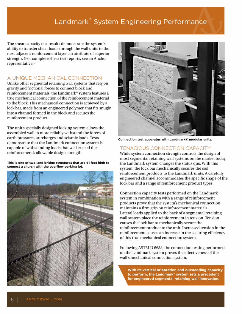
Connection test apparatus with Landmark® modular units.
The shear capacity test results demonstrate the system’s ability to transfer shear loads through the wall units to the next adjacent reinforcement layer, an attribute of superior strength. (For complete shear test reports, see an Anchor representative.)
A UNIQUE MECHANICAL CONNECTIONUnlike other segmental retaining wall systems that rely on gravity and frictional forces to connect block and reinforcement materials, the Landmark® system features a true mechanical connection of the reinforcement material to the block. This mechanical connection is achieved by a lock bar, made from an engineered polymer, that fits snugly into a channel formed in the block and secures the reinforcement product.
The unit’s specially designed locking system allows the assembled wall to more reliably withstand the forces of earth pressures, surcharges and seismic loads. Tests demonstrate that the Landmark connection system is capable of withstanding loads that well exceed the reinforcement’s allowable design strength.
TENACIOUS CONNECTION CAPACITYWhile system connection strength controls the design of most segmental retaining wall systems on the market today, the Landmark system changes the status quo. With this system, the lock bar mechanically secures the soil reinforcement products to the Landmark units. A carefully engineered channel accommodates the specific shape of the lock bar and a range of reinforcement product types.
Connection capacity tests performed on the Landmark system in combination with a range of reinforcement products prove that the system’s mechanical connection maintains a firm grip on reinforcement materials.Lateral loads applied to the back of a segmental retaining wall system place the reinforcement in tension. Tension causes the lock bar to mechanically secure the reinforcement product to the unit. Increased tension in the reinforcement causes an increase in the securing efficiency of this true mechanical connection system.
Following ASTM D 6638, the connection testing performed on the Landmark system proves the effectiveness of the wall’s mechanical connection system.
This is one of two land bridge structures that are 61 feet high to connect a church with the overflow parking lot.
With its vertical orientation and outstanding capacity to perform, the Landmark® system sets a precedent for engineered segmental retaining wall innovation.
Landmark® System Engineering Performance
ANCHORWALL.COM6 |

The Landmark system was tested for connection capacity with many reinforcement products at zero normal load, meaning the lock bar and reinforcement sit in the receiving channel with no block or other vertical load applied to the top of the units. Results show the connection capacity is typically not a function of normal load. These test results afford designers, owners, contractors and architects an extremely high level of confidence in the wall’s ability to perform. The effects of differential settlement, seismic loading, removal of block from the wall and other concerns are significantly lessened with the Landmark system’s mechanical connection.
FINITE ELEMENT ANALYSIS (FEA) OF THE LANDMARK LOCK BARThe patented, polymer-based lock bar was engineered to withstand the most extreme loading conditions in extreme environments. The polymer used to manufacture the lock bar was tested to determine applicable yield and modulus values, two of the strength characteristics used as
input for a Finite Element Analysis (FEA).
INNOVATION IN DESIGN For more than 20 years, architects, engineers and contractors have chosen Anchor™ retaining wall systems for everything from residential landscaping to high-volume, commercial tall-wall construction. The products invented by Anchor Wall Systems represent innovation in engineered design and functional versatility.
Block by block, Anchor products are built to last. These walls are cost-effective and virtually maintenance-free. In warm earth tones with a variety of face textures, Anchor segmental retaining walls enhance landscapes with enduring beauty.
At Anchor Wall Systems, these products are designed to help achieve superior results. These quality products are supported by a network of knowledgeable concrete producers, superior design technologies and engineering experts.
Results of connection test performed with the Landmark system and Mirafi Miragrid 5XT.
5000
4500
4000
3500
3000
2500
2000
1500
1000
500
0500 1000 1500 2000 2500 3000 3500
Landmark block with Miragrid 5XT geogrid
N, normal load (lbs./ft.)
Long-term allowablegeogrid design load
Peak capacityTu = 3911 + N tan 9°
Co
nn
ecti
on
cap
acit
y (
lbs.
/ft.
)
Landmark lock bar
The Landmark retaining wall system made it easier to build this exit ramp in a very tight space.
The Landmark system optimizes segmental retaining wall reliability through a mechanical connection between block facing and reinforcement materials.
Landmark System Engineering Performance
7|
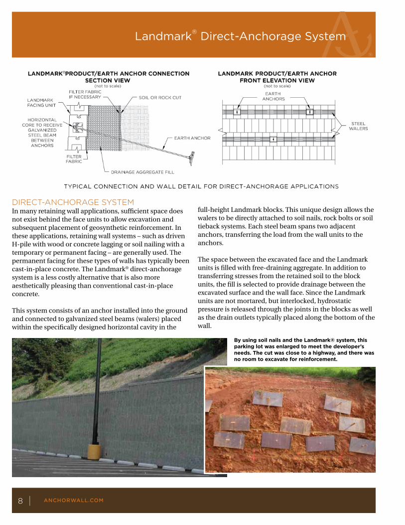
By using soil nails and the Landmark® system, this parking lot was enlarged to meet the developer’s needs. The cut was close to a highway, and there was no room to excavate for reinforcement.
DIRECT-ANCHORAGE SYSTEMIn many retaining wall applications, sufficient space does not exist behind the face units to allow excavation and subsequent placement of geosynthetic reinforcement. In these applications, retaining wall systems – such as driven H-pile with wood or concrete lagging or soil nailing with a temporary or permanent facing – are generally used. The permanent facing for these types of walls has typically been cast-in-place concrete. The Landmark® direct-anchorage system is a less costly alternative that is also more aesthetically pleasing than conventional cast-in-place concrete.
This system consists of an anchor installed into the ground and connected to galvanized steel beams (walers) placed within the specifically designed horizontal cavity in the
full-height Landmark blocks. This unique design allows the walers to be directly attached to soil nails, rock bolts or soil tieback systems. Each steel beam spans two adjacent anchors, transferring the load from the wall units to the anchors.
The space between the excavated face and the Landmark units is filled with free-draining aggregate. In addition to transferring stresses from the retained soil to the block units, the fill is selected to provide drainage between the excavated surface and the wall face. Since the Landmark units are not mortared, but interlocked, hydrostatic pressure is released through the joints in the blocks as well as the drain outlets typically placed along the bottom of the wall.
®
Landmark® Direct-Anchorage System
ANCHORWALL.COM8 |

The timbers facing the wall below a tennis court had failed. The owner wanted the wall repaired while the tennis court was in use. By using the Landmark direct- anchorage system, the wall was refaced, and play was uninterrupted.
APPLICATIONSTypical applications for the Landmark direct-anchorage system include earth retention structures where limited space prevents excavation of soil behind the retention structure (e.g., lane-widening under an overpass).
Another application of the Landmark direct-anchorage system is the repair of existing earth retention systems. Retaining walls that have experienced internal, external or facing instability may be repaired with this system. The soil nails or tieback anchors are designed to address the internal and external failure modes. The Landmark units transfer the load from soil to walers and earth anchors and provide a structurally sound solution. The case study presented on page 10 highlights this application.
The exposed face of many earth retention structures deteriorates without affecting internal and external stability. Facing stability is the only issue requiring
remediation for these existing structures. The Landmark direct-anchorage system is ideally suited for correcting this problem. Working from the bottom to the top of the structure, soil nails may be installed and connected to Landmark units, creating a new stable face in front of the old face.
Rock cuts are often susceptible to weathering of the exposed rock and local instabilities. The Landmark units, in combination with rock bolts, may be used as permanent facing for this condition, protecting the rock face from weathering and strength loss.
In summary, the Landmark direct-anchorage system provides project owners an alternative earth retention system for new construction where space is limited, and right-of-way restrictions prohibit overexcavation and replacement with conventional retaining walls. Moreover, it is a tool to repair existing deteriorated earth retention structures and to provide a permanent facing for excavations in rock.
The Landmark® system manufacturing method produces units with consistent heights, reducing construction challenges and providing a near- perfect mechanical interlock.
Landmark Direct-Anchorage System
9|
The collapsed structure
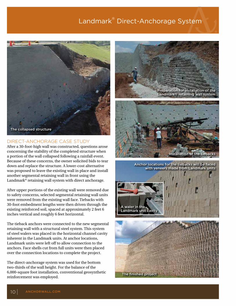
DIRECT-ANCHORAGE CASE STUDYAfter a 30-foot-high wall was constructed, questions arose concerning the stability of the completed structure when a portion of the wall collapsed following a rainfall event. Because of these concerns, the owner solicited bids to tear down and replace the structure. A lower-cost alternative was proposed to leave the existing wall in place and install another segmental retaining wall in front using the Landmark® retaining wall system with direct anchorage.
After upper portions of the existing wall were removed due to safety concerns, selected segmental retaining wall units were removed from the existing wall face. Tiebacks with 30-foot embedment lengths were then driven through the existing reinforced soil, spaced at approximately 2 feet 6 inches vertical and roughly 6 feet horizontal.
The tieback anchors were connected to the new segmental retaining wall with a structural steel system. This system of steel walers was placed in the horizontal channel cavity inherent in the Landmark units. At anchor locations, Landmark units were left off to allow connection to the anchors. Face shells cut from full units were then placed over the connection locations to complete the project.
The direct-anchorage system was used for the bottom two-thirds of the wall height. For the balance of the 6,000-square foot installation, conventional geosynthetic reinforcement was employed.
Preparation for installation of the Landmark® retaining wall system
Installation of the tiebacks
The finished project
A waler in the Landmark unit cavity
Anchor locations for the tiebacks will be faced with veneers made from Landmark units
Landmark® Direct-Anchorage System
ANCHORWALL.COM10 |

The Landmark system components are designed to work in conjunction with geosynthetic reinforcement to create tall walls capable of withstanding extreme loading conditions. Enlist the expertise of an experienced segmental retaining wall design engineer to ensure proper wall design. Contact Anchor Wall Systems for estimating, design and installation assistance.
Depths of units vary slightly in order to achieve a staggered, rock-like appearance once the wall is built. This variation does not affect estimating and does not require special installation.
Units Tapered Half-High Foundation
Approximate Dimensions* Front, 71/2" x 8" x 123/16" 71/2" x 8" x 113/4" Back, 71/2" x 8" x 1113/16"
Approximate Weight* 50 lbs. 48 lbs.
Coverage 0.42 sq. ft. 0.42 sq. ft.
Setback/System Batter Vertical Vertical
Accessories Cap
Approximate Dimensions* Long face, 33/4" x 171/4" x 103/8" Short face, 33/4" x 11" x 103/8"
Approximate Weight* 43 lbs.
Coverage 1.18 lin. ft.
Units Full Tapered Full
Approximate Dimensions* Front, 15" x 8" x 125/8" 15" x 8" x 125/8" Back, 15" x 8" x 117/8" 15" x 8" x 117/8"
Approximate Weight* 85 lbs. 80 lbs.
Coverage 0.83 sq. ft. 0.83 sq. ft.
Setback/System Batter Vertical Vertical
Minimum Inside Radius 9'
Minimum Outside Radius 6'
Accessories Lock Bar
Length 5'4"
Material Extruded polymer
*Product dimensions are height by face length by depth. Actual dimensions and weights may vary from these
approximate values due to variations in manufacturing processes. Specifications may change without notice. See your
Anchor representative for details, color options, block dimensions and additional information.
The patented, polymer-based lock bar mechanically clamps the geosynthetic reinforcement to the Landmark block.
Landmark System Components
11|

© 2016 Anchor Wall Systems. The logos, slogans, product names and other trademarks shown in this document are trademarks of Anchor Wall Systems (AWS). The wall system is made and sold under license from Anchor Wall Systems.
Anchor Wall Systems, 5959 Baker Road, Suite 390, Minnetonka, MN 55345. 73.3718.2 07/16 4017
The development of a housing site on a brownfield required a retaining wall system that was simple and rapid to install while being chemically inert to the waste in the landfill. The terraced project is up to 36 feet high and totals 26,900 square feet.
ANCHORWALL.COM12 |
Landmark®
RETAINING WALL SYSTEM