Labyrinthine Instability in Dielectric Fluids - RLE at MIT Instability in Dielectric Fluids ......
9
IEEE TRANSACTIONS ON INDUSTRY APPLICATIONS, VOL. IA-21, NO. 1, JANUARY/FEBRUARY 1985 Labyrinthine Instability in Dielectric Fluids MARKUS ZAHN, SENIOR MEMBER, IEEE, AND RAYMOND SHUMOVICH Abstract-The dual to recent work of the labyrinthine instability in magnetic fluids is demonstrated with analysis and measurements using dielectric fluids. Here polarizable fluid layers are placed within an initially uniform electric field tangential to the fluid interface separating two dielectric fluid layers. To eliminate electric space charge effects, alternat- ing electric fields must be applied at a frequency much greater than the larger reciprocal dielectric relaxation time of the fluids. Past theory and measurements have shown that a flat interface in a uniform tangential field is stable if the interface is of infinite extent. If the fluid interface has a finite thickness in the direction of the applied field, reaction fields cause nonuniform field components tangential to the fluid interface. Above a critical magnitude the resultant field destabilizes the fluid interface forming labyrinthine patterns. An interfacial stability analysis and an energy minimization method are compared to measurements. INTRODUCTION A UNIFORM magnetic field tangential to the interface between fluids of different magnetizability or a uniform electric field parallel to the interface between two different permittivity fluids is always stabilizing to small signal waves along the field, having no effect on interfacial waves trans- verse to the field [1]. However, recent work has demonstrated interfacial instability when magnetic fluid is confined with an immiscible nonmagnetic fluid between closely spaced parallel plates, with a uniform magnetic field applied normal to the plates and parallel to the thin dimension of the interface [2]- [7]. At a threshold field strength a comblike pattern develops which grows to a complicated labyrinth pattern of two simply connected but highly convoluted regions. The duality between magnetization and polarization phenomena when there is no space charge has been demonstrated whereby similar labyrinth patterns form between two dielectric fluids in an electric field [8], [9]. EXPERIMENTAL APPARATUS The test cell is shown in Fig. 1 whereby transparent glass plates with a conducting coating act as parallel plate electrodes enclosing Plexiglas spacers and the two immiscible test fluids with a flat interface along the electric field. To eliminate space charge effects, alternating electric fields are applied at a frequency much greater than the larger reciprocal dielectric relaxation time of the fluids. For our experiments we used a Paper IUSD 83-78, approved by the Electrostatic Processes Committee of the IEEE Industry Applications Society for presentation at the 1983 Industry Applications Society Annual Meeting, Mexico City, Mexico, October 3-7, 1983. Manuscript released for publication April 19, 1984. This work was supported in part by the MIT Undergraduate Research Opportunities Program and in part by the National Science Foundation under Grants ECS-8216436 and CPE-8020152. M. Zahn is with the Department of Electrical Engineering and Computer Science, Massachusetts Institute of Technology, Cambridge, MA 02139. R. Shumovich is with the Advanced Microwave Integrated Circuit Laboratory, Equipment Division, Raytheon, Inc., Spring Street, Lexington, MA. \ Transpa rent Conducting Glass Electrodes Fig. 1. Side view of test cell apparatus showing uniform electric fields far from interface and surface charges ap,, apb at spacer/dielectric interface and a,,, ab at electrode/spacer interfaces that contribute to nonuniform tangential electric field at interface. For all measurements, frequency of applied high voltage was 500 Hz. frequency of 500 Hz. To verify that a flat interface in a uniform tangential field is stable, the Plexiglas spacer is removed (1 = 0) so that the applied electric field is completely tangential to the interface. No instability developed for field strengths up to 28 kV/cm. The labyrinth would similarly not develop for magnetic fluids if the magnet pole-faces are placed without gap directly against the test fluids. EXPERIMENTS Physical parameters of test fluids used are listed in Table I. Figs. 2 and 3 show representative labyrinth patterns for various rms voltages and plate spacings t in horizontal and vertical cells with Plexiglas spacer length I = 1/8 in. In a vertical cell, larger voltages are necessary as the field instability must overcome the additional stabilizing effect of gravity with the more dense fluid below. For horizontal cells, the maximum spacing t was limited by gravity to 1116 in. Larger spacings would not have a stable flat interface with zero voltage. For some fluids a red dye was added to provide photo- graphic contrast against the adjacent clear fluid. We note that the characteristic spacing of the instability and the onset voltages are a function of material and electrode spacings. 0093-9994/85/0100-0053$01.00 © 1985 IEEE 53 Authorized licensed use limited to: MIT Libraries. Downloaded on January 22, 2009 at 14:03 from IEEE Xplore. Restrictions apply.
Transcript of Labyrinthine Instability in Dielectric Fluids - RLE at MIT Instability in Dielectric Fluids ......

IEEE TRANSACTIONS ON INDUSTRY APPLICATIONS, VOL. IA-21, NO. 1, JANUARY/FEBRUARY 1985
Labyrinthine Instability in Dielectric FluidsMARKUS ZAHN, SENIOR MEMBER, IEEE, AND RAYMOND SHUMOVICH
Abstract-The dual to recent work of the labyrinthine instability inmagnetic fluids is demonstrated with analysis and measurements usingdielectric fluids. Here polarizable fluid layers are placed within an initiallyuniform electric field tangential to the fluid interface separating twodielectric fluid layers. To eliminate electric space charge effects, alternat-ing electric fields must be applied at a frequency much greater than thelarger reciprocal dielectric relaxation time of the fluids. Past theory andmeasurements have shown that a flat interface in a uniform tangentialfield is stable if the interface is of infinite extent. If the fluid interface hasa finite thickness in the direction of the applied field, reaction fields causenonuniform field components tangential to the fluid interface. Above acritical magnitude the resultant field destabilizes the fluid interfaceforming labyrinthine patterns. An interfacial stability analysis and anenergy minimization method are compared to measurements.
INTRODUCTIONA UNIFORM magnetic field tangential to the interface
between fluids of different magnetizability or a uniformelectric field parallel to the interface between two differentpermittivity fluids is always stabilizing to small signal wavesalong the field, having no effect on interfacial waves trans-verse to the field [1]. However, recent work has demonstratedinterfacial instability when magnetic fluid is confined with animmiscible nonmagnetic fluid between closely spaced parallelplates, with a uniform magnetic field applied normal to theplates and parallel to the thin dimension of the interface [2]-[7]. At a threshold field strength a comblike pattern developswhich grows to a complicated labyrinth pattern of two simplyconnected but highly convoluted regions. The duality betweenmagnetization and polarization phenomena when there is nospace charge has been demonstrated whereby similar labyrinthpatterns form between two dielectric fluids in an electric field[8], [9].
EXPERIMENTAL APPARATUSThe test cell is shown in Fig. 1 whereby transparent glass
plates with a conducting coating act as parallel plate electrodesenclosing Plexiglas spacers and the two immiscible test fluidswith a flat interface along the electric field. To eliminate spacecharge effects, alternating electric fields are applied at afrequency much greater than the larger reciprocal dielectricrelaxation time of the fluids. For our experiments we used a
Paper IUSD 83-78, approved by the Electrostatic Processes Committee ofthe IEEE Industry Applications Society for presentation at the 1983 IndustryApplications Society Annual Meeting, Mexico City, Mexico, October 3-7,1983. Manuscript released for publication April 19, 1984. This work wassupported in part by the MIT Undergraduate Research Opportunities Programand in part by the National Science Foundation under Grants ECS-8216436and CPE-8020152.M. Zahn is with the Department of Electrical Engineering and Computer
Science, Massachusetts Institute of Technology, Cambridge, MA 02139.R. Shumovich is with the Advanced Microwave Integrated Circuit
Laboratory, Equipment Division, Raytheon, Inc., Spring Street, Lexington,MA.
\ Transpa rentConducting GlassElectrodes
Fig. 1. Side view of test cell apparatus showing uniform electric fields farfrom interface and surface charges ap,, apb at spacer/dielectric interfaceand a,,, ab at electrode/spacer interfaces that contribute to nonuniformtangential electric field at interface. For all measurements, frequency ofapplied high voltage was 500 Hz.
frequency of 500 Hz. To verify that a flat interface in auniform tangential field is stable, the Plexiglas spacer isremoved (1 = 0) so that the applied electric field is completelytangential to the interface. No instability developed for fieldstrengths up to 28 kV/cm. The labyrinth would similarly notdevelop for magnetic fluids if the magnet pole-faces are placedwithout gap directly against the test fluids.
EXPERIMENTSPhysical parameters of test fluids used are listed in Table I.
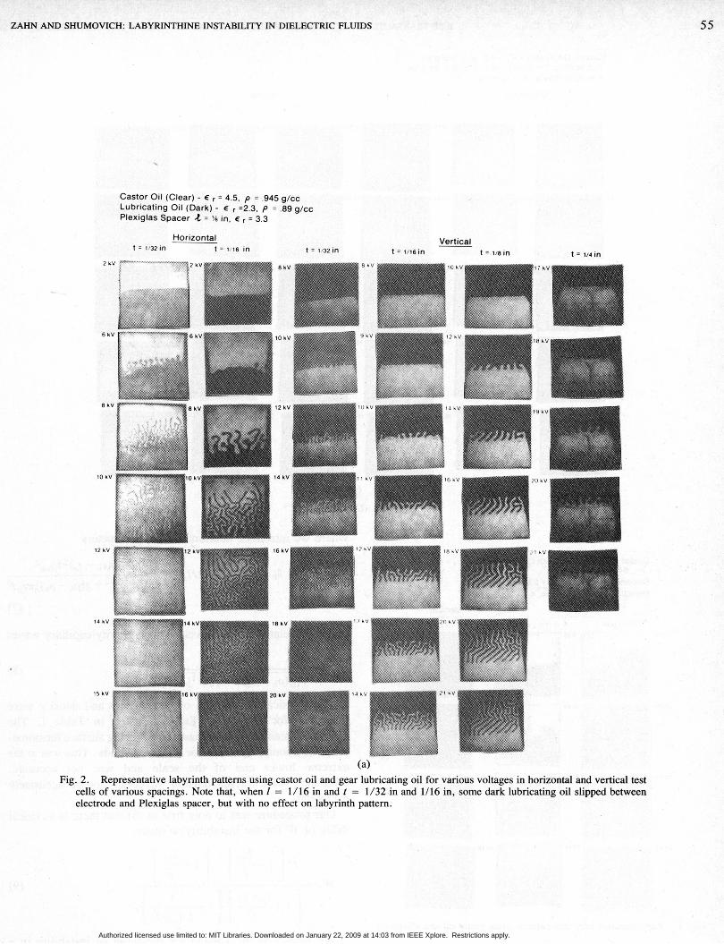
Figs. 2 and 3 show representative labyrinth patterns forvarious rms voltages and plate spacings t in horizontal andvertical cells with Plexiglas spacer length I = 1/8 in. In avertical cell, larger voltages are necessary as the fieldinstability must overcome the additional stabilizing effect ofgravity with the more dense fluid below. For horizontal cells,the maximum spacing t was limited by gravity to 1116 in.Larger spacings would not have a stable flat interface withzero voltage.
For some fluids a red dye was added to provide photo-graphic contrast against the adjacent clear fluid. We note thatthe characteristic spacing of the instability and the onsetvoltages are a function of material and electrode spacings.
0093-9994/85/0100-0053$01.00 © 1985 IEEE
53
Authorized licensed use limited to: MIT Libraries. Downloaded on January 22, 2009 at 14:03 from IEEE Xplore. Restrictions apply.

IEEE TRANSACTIONS ON INDUSTRY APPLICATIONS, VOL. IA-2 1. NO. 1, JANUARY/FEBRUARY 1985
TABLE IDENSITY AND RELATIVE PERMITTIVITIES OF TEST DIELECTRIC FLUIDS
AND PLEXIGLAS SPACER PERMITTIVITY cP
RelativeDensitv Dielectric Constant(g/cm r
Castor Oil
Clhain Lubricating Oil
Gear Lubricating Oil
Silicone Fluid
Corn Oil
Transformer Oil
Halowax Oil
.945
.925 2. 45
.89 2 . 3 3
.945 2.6
.92 5
.89
1 .28
Plexiglas spacer
3. 1
2.3
4. 7
3. 3
INTERFACIAL STABILITY THEORY
Interfacial Electric Fields
The dielectric spacer in Fig. I gives rise to depolarizingfields that cause nonuniform field components tangential andperpendicular to the fluid interface. Far from the interface, therms fields in each fluid region are
Ea = Vrms
t+21-,
VrllEb = ins
t+21l-
dExdx
8 Vrmsl(Eb - (a)( I + /lt)
7rtEv(l1 + 2f/t) (t + 2-a I) t + 2-)(3)
There is an x-directed normal field and field gradient along theinterface which is zero along the midline. Those fieldcomponents are much smaller than the tangential field and thusneglected here.
Small Signal Interfacial Waves
Past electrohydrodynamic work on the stability of fluidinterfaces consider systems of infinite extent stressed bynonuniform electric fields tangential and normal to a flatinterface. The dispersion relation for small signal perturbationof the form
est -j(kyy + kzz) k =k,2kA2 (4)
are obtained by interfacial balance of surface tension, pres-sure, and electrical forces. For our case, if we assume thefluids to wet perfectly the thick spaced electrodes, theinterface will have a radius of curvature equal to half thespacing even without electric field. The spacing t in Fig. 1 isalso considered to be so small that no interfacial variationsoccur in the z direction beyond the equilibrium interfacialcurvature due to wall wetting so that k, = 0 in (4). There arenonzero x components of the electric field and field gradientalong the interface, but at the z = 0 midpoint these terms arezero. The z component of the electric field and normal fieldgradient also vary with z along the interface but at midpoint z= 0 are given by (3). We also assume that the sinusoidal timevariations in electric field are so much faster than time for thefluids to move, that the interface only responds to the rms fieldvalues. Within these approximations, the dispersion relation isthen [10], [11]
These fields are due to polarization charge opa and Upb on thespacer-test fluid interface as well as free and polarizationcharge a, and Ub on the electrode-spacer interface as illus-trated in Fig. I
Upa (-p (-a)Ea,(p
Upb =- (Ep- b)Eb(p
or =E°Ea Ea Ob =- Eb (2)(p (p
where we recognize that the electric field in the spacer Ep isrelated to the adjacent dielectric fields as (1,Ep = eaEa neardielectric (a) and pEp = (bEb near dielectric (b).As an approximation, we assume that these surface charge
densities valid far from the interface uniformly extend to theinterface in each region. By integrating the fields due todifferential line charge elements we solve for the field and fieldgradient at the (x = 0, z = 0) midline of the interface as
E Vszls 1 1VIMS ~ +2 (al Eb'
t + 2- t+2-L EP (P J
(mI + q2)s= --yk3- k gPb-Pa)
+4 (w/t2(Eb-a)EZZ] (5)
where q I and 72 are the Darcy's drag coefficients for flow in a
Hele-Shaw cell, oy is the interfacial tension between the twofluids, yw is the surface tension at the wall, and the interfacehas equilibrium radius of curvature t/2.
With this model, we thus see that the instability of Figs. 2and 3 is driven by the nonuniform tangential electric field. Ifshas a positive real part the interface is unstable as anyperturbation grows exponentially with time. Because theelectric field term in (5) is positive, the electric field tends to
destabilize the interface. The fastest growing unstable wave
has wavelength X* = 2ir/k*0s,=0ak
W[1+ t ] [1+l1+2/tj-= *-1+
t I
(6)
54
. 5
Authorized licensed use limited to: MIT Libraries. Downloaded on January 22, 2009 at 14:03 from IEEE Xplore. Restrictions apply.
ZAHN AND SHUMOVICH: LABYRINTHINE INSTABILITY IN DIELECTRIC FLUIDS
Castor Oil (Clear) - r = 4.5. p = .945 g/ccLubricating Oil (Dark) - r =2.3, p = .89 g/ccPlexiglas Spacer S = '/8 in, e r = 3.3
t = 1/32 inHorizontal
t = 116 in
2kV .m- 2kV
i --I~~d'
t= 1/32 inVertical
t = 1/16 in t = 1/ in t = 1/4 in
8kV
10 kV 9 kV 1 12 kV.18 kV
119 k\
10 kV
12 kV
14 kV 16 kV
16 kV
18 kk
15 kV 20 kV
(a)Fig. 2. Representative labyrinth patterns using castor oil and gear lubricating oil for various voltages in horizontal and vertical test
cells of various spacings. Note that, when I = 1/16 in and t = 1/32 in and 1/16 in, some dark lubricating oil slipped betweenelectrode and Plexiglas spacer, but with no effect on labyrinth pattern.
55
8 kV t-- -----M"%S kV101911210. 12 kV ilMillillM IO kVMomjj..14o
141kV
Authorized licensed use limited to: MIT Libraries. Downloaded on January 22, 2009 at 14:03 from IEEE Xplore. Restrictions apply.

IEEE TRANSACTIONS ON INDUSTRY APPLICATIONS, VOL. IA-21, NO. 1, JANUARY/FEBRUARY 1985
Castor Oil (Clear) - sE r 4.5. p .945 g/ccLubricating Oil (Dark) - e, =2.3. p = .89 g/ccPlexiglas Spacer t= 16 in. r = 3.3
Horizontalt= 1 16 in
6 kV
12 kl
14Wk
t= 1 32in t = 116 in
Verticalt= viain
SkV
10 lki
13kW
5lkV
18 kV16kV
12Wk
20 kl
22 k'
(b)Fig. 2. (Continued).
where we introduce nondimensional parameters
Castor Oil (Dark, dyed with Congo Red #3) - C r = 4 5.p = .945 g/ccSilicone Oil (Clear) - f r = 2.6, p = .945 g/ccPlexiglas Spacer 4 = I/e in, e r = 3.3
Horizontal Vertical
t= 32in t 16 in t=tii 32in15 kV Z kV 18 kV g
20 lkV k 15 kV 200kV
22kV~~~~~~2 kVk V77 2i
24 kV _ 22 24 kV61.
ea b.ea=- , b=- ,
Cep ept= t/l, W=
4(Eb -Ca)2 Vrs2
[4'yW/t2 + g(Pb-Pa)]7EpI3
and X0 is related to the wavelength of gravity-capillary waves
xo= *i (8)='9g(Pb-Pa) + 4'yw/t2/3y(
The physical parameters of permittivity and density weremeasured for all tested fluids as listed in Table I. Theinterfacial tension -y was measured by a ring surface tensiome-ter to be about 1 dyne/cm for all tested fluids. This was at theextreme lower end of the scale and was not accurate.Similarly, wall surface tension -yw could not be accuratelymeasured.Our procedure was to note first in (6) that there is a critical
value of W for the instability to onset
i4 [ I + ei.w= t4+~
[ 1 ea + eb
Fig. 3. Representative labyrinth patterns using castor oil and silicon oil.
[ t]
[1 1+2/T]We measured the voltage for the onset of instability in a
horizontal cell so that g = 0 and then calculated the value of
t= 4 int 321in
14 kV
i6 kV
*8 kV
20 kV
22 kV
i*kV
l
Authorized licensed use limited to: MIT Libraries. Downloaded on January 22, 2009 at 14:03 from IEEE Xplore. Restrictions apply.
ZAHN AND SHUMOVICH: LABYRINTHINE INSTABILITY IN DIELECTRIC FLUIDS
25
20
151
10
5
Oils ( m) V'ert ical HorizontCastor/gear 3.07 0 0Castor/gear 1.62 * OCorn/Trans former 3.07 Aorn/Castor 3.07 *Castor/Transformer 3.07 vCastor/Chain 3.07
130
I_ /0
5 10(W measured)
c
150
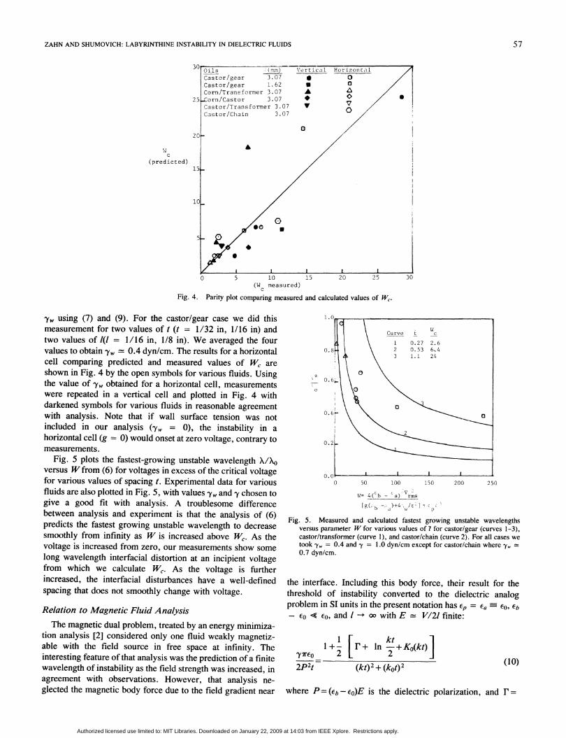
Fig. 4. Parity plot comparing measured and calculated values of Wc.
'ye, using (7) and (9). For the castor/gear case we did thismeasurement for two values of t (t = 1/32 in, 1/16 in) andtwo values of 1(1 = 1/16 in, 1/8 in). We averaged the fourvalues to obtain y, 0.4 dyn/cm. The results for a horizontalcell comparing predicted and measured values of W, areshown in Fig. 4 by the open symbols for various fluids. Usingthe value of y, obtained for a horizontal cell, measurementswere repeated in a vertical cell and plotted in Fig. 4 withdarkened symbols for various fluids in reasonable agreementwith analysis. Note that if wall surface tension was notincluded in our analysis (-yw = 0), the instability in a
horizontal cell (g = 0) would onset at zero voltage, contrary tomeasurements.
Fig. 5 plots the fastest-growing unstable wavelength X/X0versus W from (6) for voltages in excess of the critical voltagefor various values of spacing t. Experimental data for variousfluids are also plotted in Fig. 5, with values -yw and 'y chosen togive a good fit with analysis. A troublesome differencebetween analysis and experiment is that the analysis of (6)predicts the fastest growing unstable wavelength to decreasesmoothly from infinity as W is increased above W,. As thevoltage is increased from zero, our measurements show some
long wavelength interfacial distortion at an incipient voltagefrom which we calculate W,. As the voltage is furtherincreased, the interfacial disturbances have a well-definedspacing that does not smoothly change with voltage.
Relation to Magnetic Fluid AnalysisThe magnetic dual problem, treated by an energy minimiza-
tion analysis [2] considered only one fluid weakly magnetiz-able with the field source in free space at infinity. Theinteresting feature of that analysis was the prediction of a finitewavelength of instability as the field strength was increased, inagreement with observations. However, that analysis ne-glected the magnetic body force due to the field gradient near
50 100 150
W= 4( b - a) rms
[g(bG,1:-~ )+4-, /t- C
250
Fig. 5. Measured and calculated fastest growing unstable wavelengthsversus parameter W for various values of 7 for castor/gear (curves 1-3),castor/transformer (curve 1), and castor/chain (curve 2). For all cases wetook oyw = 0.4 and .y = 1.0 dyn/cm except for castor/chain where ,,0.7 dyn/cm.
the interface. Including this body force, their result for thethreshold of instability converted to the dielectric analogproblem in SI units in the present notation has cp = Ea 60 Eb
<<e0, and I -+ oo with E = V/21 finite:
i+- [ r+ ln --+ Ko(kt)],<ec0 2 22p2t (kt)2 + (kot)2
(10)
where P = (Eb -Eo)E is the dielectric polarization, and r=
/
14c
(predicted)
57
Jr
0
Authorized licensed use limited to: MIT Libraries. Downloaded on January 22, 2009 at 14:03 from IEEE Xplore. Restrictions apply.

IEEE TRANSACTIONS ON INDUSTRYf APPLICATIONS, VOL. IA-21, NO. 1. JANUARY/FEBRUARY 1985
0.5772 is the Euler constant,
k0={[g(pb -P.)+4,yw/t2]/3y} 1/2
is the gravity capillary wavenumber augmented by wallsurface tension, and K0 is the zeroth-order modified Besselfunction.
In the same limits, (9) gives the onset of instability as
zP2t (kt)2 + (kot)2
ktFig. 6. Wavenumber at incipience of instability for various gravity-capillary
wavenumbers k0 comparing interfacial force balance approach (solid lines)to energy minimization approach [2] (dashed lines) for one weaklypolarizable fluid with electric field source in free space at infinity.
closed and the fluids will arrange themselves to minimize thetotal energy. For the same charge Q, the terminal voltage willbe different with and without dielectric fluids. A similar typeof energy analysis has been applied to bubble elongation in aliquid capacitor [131.The final electric fields Ea and E5 are actually complicated
functions of position to be integrated in (14). However, as asimplification we assume in (15) that Ea and Eb are uniform ineach dielectric being the value at the midpoint of eachdielectric including the depolarizing effects of polarizationcharge q2, U2 on the spacer-dielectric fluid interface and freeand polarization charge an, rIb on the electrode/spacerinterface.With both dielectrics in place and stressed by a constant
voltage V0 with average charge per unit area Q, the averagefield in each dielectric is
ptv2Cpt±+ 2/C
(eat + 2ka) ea I + Cb
Cpt+ 2la 2Wb Cptt+2kb 1+-
L- Wa WI
Q.0
I C
(11)
Both (10) and (11) are plotted in Fig. 6 and are seen to befairly close and thus probably not resolvable by experiment.
LIMITING LABYRINTH STATE
The interfacial stability analysis provides a good measurefor the onset of instability and its dependence on materialproperties, geometry, and field strength. However, it providesno information on the limiting labyrinth state once theinterface is no longer flat. Then there is a mutual invasion ofthe two phases in which fringes continually bifurcate, finallyreaching a steady-state labyrinth pattern comprising twosimply connected but highly convoluted regions.To solve for the limiting state of a horizontal labyrinth, we
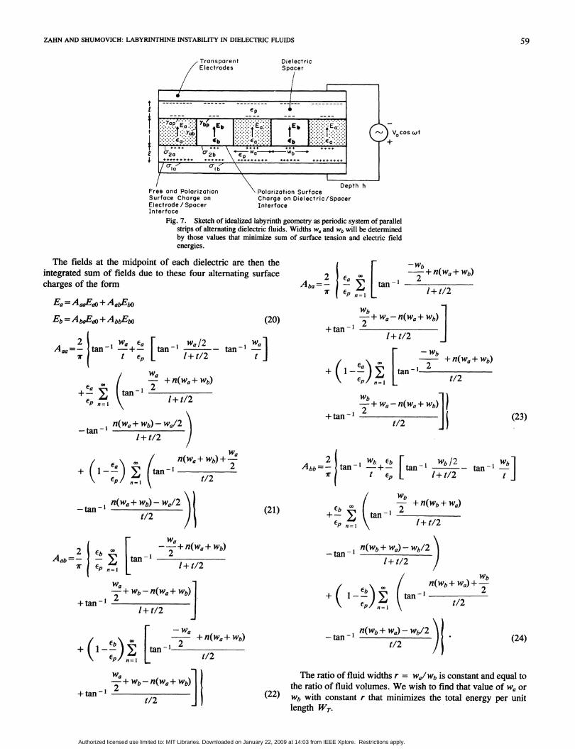
extend the energy method analysis developed by Rosenweigfor magnetic fluids [8]. We neglect the presence of convolu-tions, nodes, cul-de-sacs, and other complicating features ofthe real labyrinth and consider a repeating pattern of parallelfluid strips shown in Fig. 7.The total energy of one period of the repeating pattem of
width Wa + w, is due to the electrostatic, WE, and surfacetension W, energies
WT(Wa+ WI) WE+ Ws (12)
where WT is the average energy per unit length in the zdirection.The interfacial energy for a system of height h is
(13)
where oyj is the appropriate surface tension at each of the
interfaces.The electric energy stored in the system is [121
WE= -X (C-O)E El dV
--E [(a-EO)WaEa+(EC -Co)w,Ebith2
where - Eoit is the electric field in the test cell withelectrode charge per unit area Q in the absence of dielectricfluids
QQ (16)CO
and Ea and Eb are the average final electric fields when bothdielectric fluids are in place with the same value of electrodecharge per unit area Q. It is important to express WE as a state
function of Q and not the terminal voltage. By keeping Qconstant, no electrical energy can be input so that the system is
(14) Eb --VoE t _ 2IE
(15)(£Ept+21Cb)
QCa I b
pt + 2ICa Wb Cpt + 2Ib Wa
1+- I+--Wa WI,o
(17)
The interfacial charges in Fig. 7 at dielectric-spacer and
electrode-spacer interfaces are then
#yla- E(P
COCb ECp
P(Ca b (C-
(18)
(19)
-= 2h[w.ayp + WfYbp + Yabt] Q
58
Authorized licensed use limited to: MIT Libraries. Downloaded on January 22, 2009 at 14:03 from IEEE Xplore. Restrictions apply.
ZAHN AND SHUMOVICH: LABYRINTHINE INSTABILITY IN DIELECTRIC FLUIDS
Fi. 7. Sktc of idaie layit emtya eidcsse fprle
\ b+ + F+++ 4: + ,
C,2 F2b \- *- b-fi +F++F+F+++ +tFF.... .........o ++++++ .........F+i
17 I b
\ [)~~~~~epthhFree ond Polarizaition Polarizotion SurfaceSurface Charge on Charge on Dielectric/SpacerElectrode / Spocer InterfaceInterface
Fig. 7. Sketch of idealized labyrinth geometry as periodic system of parallelstrips of alternating dielectric fluids. Widths w" and wb will be determinedby those values that minimize sum of surface tension and electric fieldenergies.
The fields at the midpoint of each dielectric are then theintegrated sum of fields due to these four alternating surfacecharges of the form
Ea=AaaE +AabEbO
Eb = Ab,GEO + AbbEbo (20)
A-a=2 tan- WaE-a [tan-I wa/2 _ tan _]Wa7r I t P I+t/2 t
(tan-Pn
CPn=l
- Wb*_ + n(wa+ Wb)
tan - 21+ t/2
-2 + Wa-n(Wa+ Wb)+tan-
1+ (/2J
+ I n= [a + n(Wa +Wb)2
I + t/2
-tn1 fl(Wa+Wb)-Wa/2-t=Il nIw. wb1+w(/21+t/2 /
/ n(Wa+ Wb) + 2uul- 1 .,/
t/2P n=l
an(w.+ wb)-w12 i
t/2
-W_ +n(wa+ Wb)an-1
2
t/2
-2 +Wa-n(Wa + Wb)+tan
t/2
Abb=- ta -- _ tan -
l t C-P
(21)+- n=ltan-
4En
W-b /21+ t/2 tan-i b
t
2 + n(wb+ w,)
1+ t/2
2AbbAob=- - I;7r Ep n=l
-+n(w1+wb)tan - 1 2
I+ t/2
-+ Wb-n(Wa + Wb)
+tan -'1+ t/2
Wa
F _ + n(wa+ Wb)
tant/2
e n
W
-+ Wb-n(Wa+ Wb) |
+tan-1 2
t/2
fl"(Wb+ We)- wI/2'\
-tan-1n -- w --
1+ t/2
n/t(wb+ Wa) +-W+ 1--) tanI_
(Wb+wa)-Wb/2)2
-tan- -n---w.-(/t12 /
(24)
The ratio of fluid widths r = w/wIw is constant and equal tothe ratio of fluid volumes. We wish to find that value of wa or
(22) wb with constant r that minimizes the total energy per unitlength WT.
(23)
59
Authorized licensed use limited to: MIT Libraries. Downloaded on January 22, 2009 at 14:03 from IEEE Xplore. Restrictions apply.

IEEE TRANSACTIONS ON INDUSTRY APPLICATIONS. VOL. IA-21, NO. 1, JANUARY/FEBRUARY 1985
Using (13)-(24) in (12) yields
WT=2h rTp + + Wabt ][1+l/r l+r wb(l+r)
1- htEo (1 + l/r)
+ (Eb °) (AbaEaO+AbbnEbO)](I + r)
(25)
Note in (25) that Eo, EaO, and Ebo do not depend on Wb but onlyon the constant r so that the energy minimization condition willdepend directly on the depolarization factors of (2l)-(24)yielding
dWT= 0 NE= AEoVo
dwb 4Yab
( [a- - rdAaa
Wb i_dEab
(b -O) ]dAba /(1 + NJ)d+- b
dwVb
+ (ib -O) dAbb- I +2l T)dlVb
(26)
where we introduce the nondimensional electric Bond numberNE and normalize all permittivities to -p as in (7) and alllengths to t
T=IIt, Wb = Wb/t. (27)
Fig. 8 plots the dependence of the nondimensional electricBond number NE as a function of Wb = wb/t for variousvalues of r = Wa/Wb and T = lit for permittivity parameterscorresponding to dielectric fluids of castor oil and thelubricating oil with a Plexiglas dielectric spacer. This plot wasobtained using (26), taking 2000 terms in the infinite series of(21)-(24), and illustrates a minimum value of electric Bondnumber necessary to establish the labyrinth pattern. For therepresentative values in our experiments, with r = wa/wb =
1, the minimum value of NE is about 25 with w 1 to 2.Higher values of voltage increase NE and thus decrease Wb.A curious feature of Fig. 8 is that Wb is double valued in the
the range of NE just above threshold. This is most likely aresult of the approximations made in computing the electricfields in each fluid strip. These features of Fig. 8 are similar tothat found in the analogous magnetic fluid problem where onlyone fluid was magnetizable and the magnet pole faces were atinfinity [8]. Here, the analysis is more complicated becauseboth fluids and spacers are polarizable and the electrodes are afinite distance from the fluids.
Table II shows the predicted critical voltage of 1.5-2 kV
U
Uz C
900 V
800s
700
600
500
200
100
Lubricating Oil Ear = 2.3Castor Oil, Cir 4-5Plexiglas spacer, <pr -- 3.3
E 'ar O7aE=p 0.70aEp
E.=!bp -1.36b lep
sEo ep = 0.30
wab
0 2 3
Wb - Wb/t
r = 1,'=0.25r-= I,ja0.50r=- 1, Z - I.00rf 2,; a.00
4 5
Fig. 8. Nondimensional electric Bond number NE as function of Wb forvarious values of r = Wa/Wb and I = lit for permittivity parameterscorresponding to castor oil and lubricating oil with Plexiglas spacer. Thisplot used 2000 terms in infinite series of (21)-(24).
TABLE II
l/2
(?rom Eqs.£ t 16 and 17 (Yab-.ON11tOmp
(inches) (inohes) ~it with r-1) N-25)
1/16 1/32 2 1.66zlO 1.43
1/16 1/16 1 1.38x1O 1.57
1/8 1/32 4 .92x10' 1.93
1/8 1/16 2 .83x10' 2.0
Calculated critical voltage VO necessary for labyrinth formationin a horizontal coll using the fluids listed in Fig. (8) with N225,rawa/wb=, Tab=1 dyne/cm (.001 Nts/m).
necessary for labyrinth formation in a horizontal cell using thefluids listed in Fig. 8 to be in good agreement withmeasurements. The surface tension value of 1 dyn/cm for -Yabwas used since this value best fit the data of Fig. 5.
CONCLUDING REMARKS
The linear stability analysis of (4)-(9) predicts the voltagenecessary for a flat interface to become first unstable includingthe effects of gravity and wall surface tension. For a horizontalcell so that gravity has no effect and with no wall surfacetension, this incipient voltage is zero. However, in this limit,the minimum energy analysis of (12)-(27) shows that athreshold voltage is still necessary for full labyrinth develop-ment, in agreement with measurements. Lesser voltagesdisturb the flat interface but do not have complete interpenetra-tion of fluids.
ACKNOWLEDGMENT
Stimulating discussions with R. E. Rosensweig of ExxonResearch and Engineering Co. are gratefully appreciated.Khalid Rahmat, an M.I.T. undergraduate student, assisted inpreparing Figs. 4, 5, and 8.
60
400_
300_
Authorized licensed use limited to: MIT Libraries. Downloaded on January 22, 2009 at 14:03 from IEEE Xplore. Restrictions apply.

ZAHN AND SHUMOVICH: LABYRINTHINE INSTABILITY IN DIELECTRIC FLUIDS
REFERENCES[11 J. R. Melcher, Field Coupled Surface Waves. Cambridge, MA:
MIT Press, 1963.[21 A. 0. Tsebers and M. M. Maiorov, "Comblike instability in thin
layers of a magnetic liquid," Magnetohydrodynamics, pp. 22-26,Apr.-June 1980.
[3] R. E. Rosensweig, "Pattern formation in magnetic fluids," inEvolution ofOrder and Chaos in Physics, Chemistry, and Biology,H. Haken, Ed. Berlin, Germany: Springer-Verlag, 1982, pp. 52-64.
[4] L. T. Romankiw, M. M. G. Slusarczyk, and D. A. Thompson,"Liquid magnetic bubbles," IEEE Trans. Mag., vol. MAG-11, pp.25-28, 1975.
[5] R. E. Rosensweig, "Magnetic fluids," Sci. Amer., vol. 247, pp. 136-145, 1982.
[6] A. 0. Tsebers and M. M. Maiorov, "Magnetostatic instabilities inplane layers of magnetizable liquids,"pp. 27-35, Jan.-Mar. 1980.
[7] A. 0. Tsebers and M. M. Maiorov, "Structures of interface of a bubbleand magnetic fluid in a field," pp. 15-20, July-Sept. 1980.
[81 R. E. Rosensweig, M. Zahn, and R. Shumovich, "Labyrinthineinstability in magnetic and dielectric fluids," J. Magnetism MagneticMater., vol. 39, pp. 127-132, Nov. 1983.
[9] M. Zahn and R. Shumovich, "Labyrinthine instability in dielectricfluids," in Conf. Rec. IEEE Ind. Appi. Soc., Oct. 1983, pp. 1142-1148; also 1983 Annu. Rep. Conf. Electrical Insulation andDielectric Phenomena, Oct. 1983, pp. 170-175.
[10] M. Zahn and R. E. Rosensweig, "Stability of magnetic fluidpenetration through a porous medium with uniform magnetic fieldoblique to the interface," IEEE Trans. Magn., vol. MAG-16, pp.275-282, 1980.
[11] J. R. Melcher, Continuum Electromechanics. Cambridge, MA:MIT Press, 1981, sec. 8.11.
[12] D. T. Paris and F. K. Hurd, Basic Electromagnetic Theory. NewYork: McGraw-Hill, 1969, pp. 286-287.
[131 R. Meyrueix, P. Atten, and R. Tobazeon, "On the behavior of a planegaseous cavity in an insulating liquid subjected to an ac voltage," IEEETrans. Elec. Insul., vol. EI-18, pp. 65-77, Feb. 1983.
Markus Zahn (S'68-M'71-SM'78) received theB.S.E.E., M.S.E.E., E.E., and Sc.D. degrees fromthe Massachusetts Institute of Technology, Cam-bridge, in 1968, 1968, 1969, and 1970, respec-tively.From 1970 to 1980 he was a Professor of
Electrical Engineering at the University of Florida,Gainesville. He joined the MIT Faculty in 1980 andis currently an Associate Professor of ElectricalEngineering and Computer Science working in theMIT High Voltage Research Laboratory of the
Laboratory for Electromagnetic and Electronic Systems. He is the author ofElectromagnetic Field Theory: A Problem Solving Approach (Wiley,1979). He holds three patents for his work concerning the elimination ofparasitic current in batteries. His fields of research and interest includeelectro-optical field mapping measurements, high-voltage charge transportand breakdown phenomena in dielectrics, electrohydrodynamic. interactionswith charged fluids, ferrohydrodynamic interaction with magnetizable fluids,and continuum electromechanics of electrofluidized beds.
Dr. Zahn has received numerous awards for excellence in teaching. In 1982he received a Ferrofluidics Advanced Study Fellowship. He has served asChairman and Program Chairman in numerous professional conferences,including the 1982 and 1983 Conferences on Electrical Insulation andDielectric Phenomena.
Raymond Shumovich was born and raised inPittsburgh, PA. He received the B.S. degree inelec'ical engineering from the Massachusetts Insti-tute of Technology, Cambridge, in June, 1984.He is currently employed at the Advanced Micro-
wave Integrated Circuit Laboratory of Raytheon'sEquipment Division, in Sudbury, MA.
61
Authorized licensed use limited to: MIT Libraries. Downloaded on January 22, 2009 at 14:03 from IEEE Xplore. Restrictions apply.
![Muscle-like high-stress dielectric elastomer actuators ... · to various failure modes as shown in Fig. 1(a), for examples: partial discharge[11], electromechanical instability[12,](https://static.fdocuments.us/doc/165x107/606fef72549e5f1ee437ed9c/muscle-like-high-stress-dielectric-elastomer-actuators-to-various-failure-modes.jpg)