
LAB 3 - Working With Alignments - index html — · LAB 3 - Working With Alignments ... The...
20
Colorado Department of Transportation Page 69 LAB 3 - Working With Alignments Alignments are reference points that are used to relate the design world to the real world. The coordinates that make up the alignment are located at the construction site and measurements for design elements are taken from these coordinates. In this lab, a horizontal and vertical alignment is created that represents the new flowline for a drainage channel. The new flowline must match the existing flowline horizontally and vertically at the beginning and end of the alignment as well as at an inlet structure in the middle. Chapter Objectives: Import a horizontal alignment from a graphic element. Add a horizontal curve to the alignment. Create a profile. Define a vertical alignment. The following files are used in this lab: C:\Workspace\Workspace-CDOT_XM\Standards-Global\InRoads\Preferences\ CDOT_Civil.xin C:\Projects\12345\Bridge\Drawings\Reference Files\12345BRDG_Model-Drain.dgn C:\Projects\12345\Bridge\Drawings\Reference Files\12345BRDG_Prof.dgn C:\Projects\12345\ROW_Survey\InRoads\DTM\12345_Drain Lab 3.1 - Draw Graphic Elements for the Horizontal Alignment There are numerous methods for entering horizontal alignment data into InRoads. Most of these methods are designed for survey and roadway geometry. Because this lab is not concerned with roadway geometric design criteria, the alignment can be laid out graphically then imported into inRoads. Section Objectives: ♦ Create MicroStation graphic elements that represent the alignment. ♦ Create a complex chain from those elements. ♦ Import the graphic as a horizontal alignment. ♦ Change the direction of the alignment, if needed. 1. Start MicroStation and InRoads using the 12345BRDG_Model-Drain.dgn file. 2. In the main InRoads dialog box, verify that the CDOT_Civil.xin is loaded. 3. From the InRoads menu bar, select File > Open. 4. Navigate to the C:\Projects\12345\ROW_Survey\InRoads\DTM\ directory and open the 12345_Drain file
Transcript of LAB 3 - Working With Alignments - index html — · LAB 3 - Working With Alignments ... The...

Colorado Department of Transportation Page 69
LAB 3 - Working With Alignments
Alignments are reference points that are used to relate the design world to the real world. The coordinates that make up the alignment are located at the construction site and measurements for design elements are taken from these coordinates.
In this lab, a horizontal and vertical alignment is created that represents the new flowline for a drainage channel. The new flowline must match the existing flowline horizontally and vertically at the beginning and end of the alignment as well as at an inlet structure in the middle.
Chapter Objectives:
Import a horizontal alignment from a graphic element.
Add a horizontal curve to the alignment.
Create a profile.
Define a vertical alignment.
The following files are used in this lab:
C:\Workspace\Workspace-CDOT_XM\Standards-Global\InRoads\Preferences\ CDOT_Civil.xin
C:\Projects\12345\Bridge\Drawings\Reference Files\12345BRDG_Model-Drain.dgn
C:\Projects\12345\Bridge\Drawings\Reference Files\12345BRDG_Prof.dgn
C:\Projects\12345\ROW_Survey\InRoads\DTM\12345_Drain
Lab 3.1 - Draw Graphic Elements for the Horizontal Alignment
There are numerous methods for entering horizontal alignment data into InRoads. Most of these methods are designed for survey and roadway geometry. Because this lab is not concerned with roadway geometric design criteria, the alignment can be laid out graphically then imported into inRoads.
Section Objectives:
♦ Create MicroStation graphic elements that represent the alignment.
♦ Create a complex chain from those elements.
♦ Import the graphic as a horizontal alignment.
♦ Change the direction of the alignment, if needed.
1. Start MicroStation and InRoads using the 12345BRDG_Model-Drain.dgn file.
2. In the main InRoads dialog box, verify that the CDOT_Civil.xin is loaded.
3. From the InRoads menu bar, select File > Open.
4. Navigate to the C:\Projects\12345\ROW_Survey\InRoads\DTM\ directory and open the 12345_Drain file
Page 70 Colorado Department of Transportation
LAB 3 - Working With Alignments Bridge Essentials Using InRoads XM
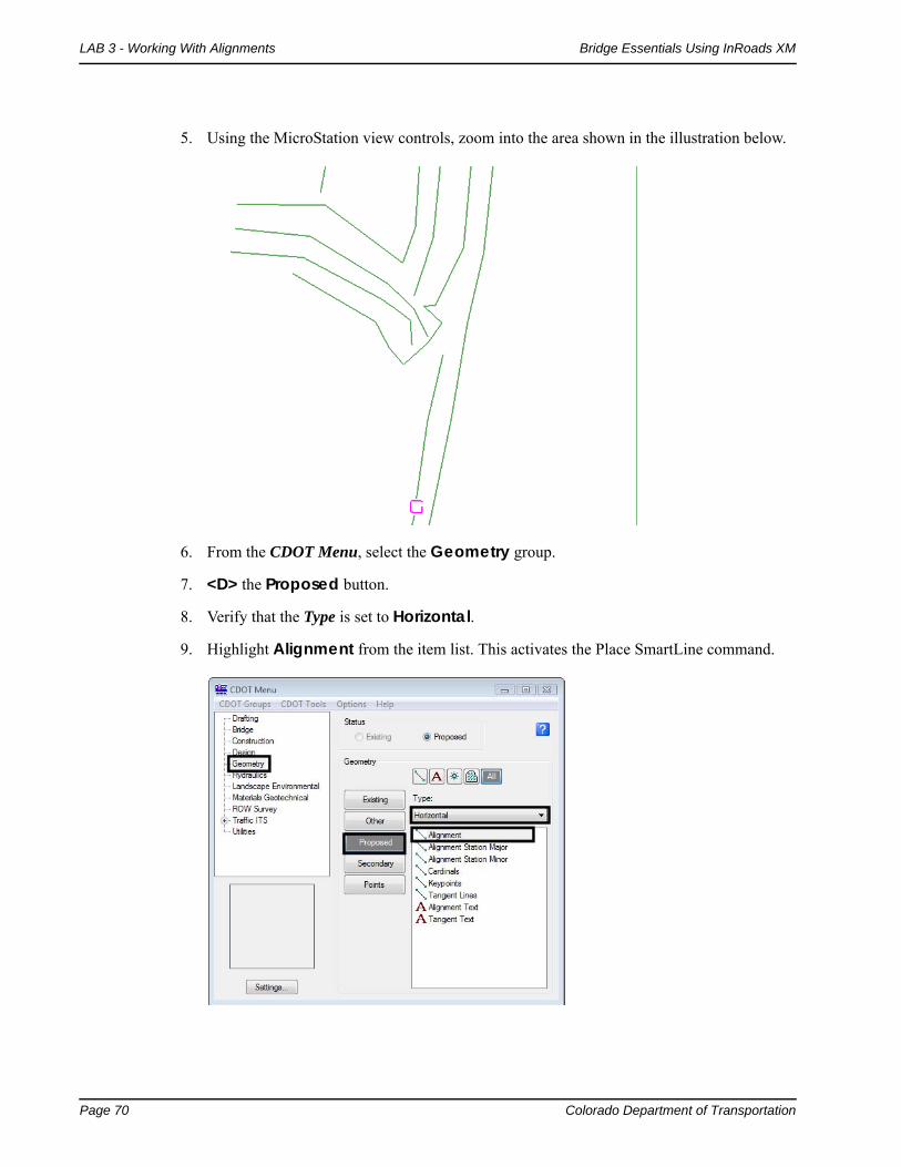
5. Using the MicroStation view controls, zoom into the area shown in the illustration below.
6. From the CDOT Menu, select the Geometry group.
7. <D> the Proposed button.
8. Verify that the Type is set to Horizontal.
9. Highlight Alignment from the item list. This activates the Place SmartLine command.

Colorado Department of Transportation Page 71
Bridge Essentials Using InRoads XM LAB 3 - Working With Alignments
10. <T> then <D> on the points shown in the illustration below.
Points 1 and 2 are on the flowline of the existing channel. Point 3 is in the center of the top side of the inlet structure.

Page 72 Colorado Department of Transportation
LAB 3 - Working With Alignments Bridge Essentials Using InRoads XM
11. <R> to exit the Place SmartLine command. The result is a linestring placed as shown below.
12. Zoom out to see the channel below the inlet.

Colorado Department of Transportation Page 73
Bridge Essentials Using InRoads XM LAB 3 - Working With Alignments
13. <T> then <D> on the points shown in the illustration below.
This line will match the new channel to the existing channel below the inlet.
14. <R> to exit the Place SmartLine command. The result is a linestring placed as shown below.
In order to create an alignment from these elements must match up end to end. The MicroStation Extend Elements to Intersection is used to accomplish this.

Page 74 Colorado Department of Transportation
LAB 3 - Working With Alignments Bridge Essentials Using InRoads XM
15. From the MicroStation Main toolbar select the Extend Elements to Intersection command.
16. <D> on the first linestring near the inlet.
17. <D> the second linestring near the end closest to the inlet.
Note: If you are having trouble selecting the correct lines, the green terrain lines can be deleted to get them out of the way.

Colorado Department of Transportation Page 75
Bridge Essentials Using InRoads XM LAB 3 - Working With Alignments
The MicroStation Create Complex Chain command is used to join the two linestrings into a single element which can be imported into InRoads as a horizontal alignment.
18. From the MicroStation Main toolbar select the Create Complex Chain command.
19. <D> on each line, then <D> in a blank area to accept the elements.
20. <R> to exit the Create Complex Chain command.
This completes the linestring that will be used for the alignment. Next, the linestring is imported into InRoads.
Section Summary:♦ MicroStation graphic elements can be used to create InRoads alignments.
♦ Multiple elements can be joined to create a single element which is easier to import into a single alignment.
Lab 3.2 - Create a Geometry Project and Import a Horizontal Alignment
Section Objectives:
♦ Create a new InRoads geometry project.
♦ Import the chain into InRoads.
The first step is to create a Geometry Project. This is the file that holds the horizontal and vertical alignment data.
1. Start MicroStation and InRoads (if they are not already started) and open the 12345BRDG_Model-Drain.dgn file.
2. If InRoads was already opened, save and close any InRoads data files that are open.
3. From the inRoads menu, open the C:\Projects\12345\ROW_Survey\InRoads\DTM\ 12345_Drain file.

Page 76 Colorado Department of Transportation
LAB 3 - Working With Alignments Bridge Essentials Using InRoads XM
4. From the InRoads main menu, select File > New.
5. In the New dialog box, <D> the Geometry tab.
6. Set the Type to Geometry Project.
7. Key in 12345-Drain for the Name.
8. Key in New channel project for the Description.
9. <D> Apply then <D> Close to dismiss the dialog box.
10. On the InRoads Explorer, <D> the Geometry tab.
11. <R> on the 12345-Drain geometry project and select Save from the right click menu.

Colorado Department of Transportation Page 77
Bridge Essentials Using InRoads XM LAB 3 - Working With Alignments
12. In the Save As dialog box, navigate to the C:\Projects\12345\Bridge\InRoads\ folder.
13. At the bottom of the dialog box, use the Active drop down menu to reselect the 12345-Drain geometry project. This will automatically fill in the name field so that the name on the hard drive matches what is shown in InRoads.
14. <D> Save then <D> Cancel to dismiss the dialog box.
Next, the horizontal alignment is created from the graphic element drawn above.
15. From the InRoads menu bar, select File > Import > Geometry.
16. In the Import Geometry dialog box, verify that the From Graphics tab is selected.
17. Set the Type to Horizontal Alignment.
18. Key in Channel_Flowline for the Name.
19. Key in Channel alignment for project 12345 for the Description.
20. Set the Style to ALG_PRO.
Page 78 Colorado Department of Transportation
LAB 3 - Working With Alignments Bridge Essentials Using InRoads XM
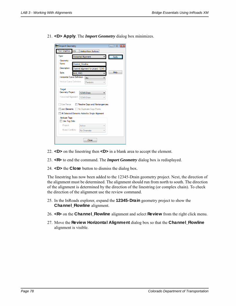
21. <D> Apply. The Import Geometry dialog box minimizes.
22. <D> on the linestring then <D> in a blank area to accept the element.
23. <R> to end the command. The Import Geometry dialog box is redisplayed.
24. <D> the Close button to dismiss the dialog box.
The linestring has now been added to the 12345-Drain geometry project. Next, the direction of the alignment must be determined. The alignment should run from north to south. The direction of the alignment is determined by the direction of the linestring (or complex chain). To check the direction of the alignment use the review command.
25. In the InRoads explorer, expand the 12345-Drain geometry project to show the Channel_Flowline alignment.
26. <R> on the Channel_Flowline alignment and select Review from the right click menu.
27. Move the Review Horizontal Alignment dialog box so that the Channel_Flowline alignment is visible.

Colorado Department of Transportation Page 79
Bridge Essentials Using InRoads XM LAB 3 - Working With Alignments
28. In the Review Horizontal Alignment dialog box, toggle the mode to Element. This causes the first element of the alignment to highlight.
29. <D> Close to dismiss the Review Horizontal Alignment dialog box.
If the element highlights as shown in the image above, the alignment is running the wrong way.
To change the direction of the alignment:
Important! Complete steps 30 through 33 only if your alignment starts at the south end, as illustrated above.

Page 80 Colorado Department of Transportation
LAB 3 - Working With Alignments Bridge Essentials Using InRoads XM
30. From the InRoads main menu bar, select Geometry > Utilities > Transpose.
31. In the Transpose dialog box, <D> the “target” button then <D> on the alignment. <D> in a blank area to accept.
Colorado Department of Transportation Page 81
Bridge Essentials Using InRoads XM LAB 3 - Working With Alignments
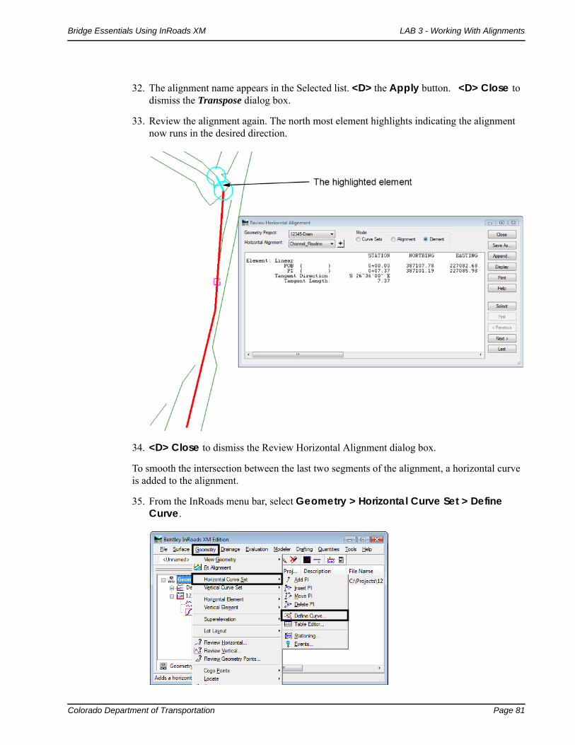
32. The alignment name appears in the Selected list. <D> the Apply button. <D> Close to dismiss the Transpose dialog box.
33. Review the alignment again. The north most element highlights indicating the alignment now runs in the desired direction.
34. <D> Close to dismiss the Review Horizontal Alignment dialog box.
To smooth the intersection between the last two segments of the alignment, a horizontal curve is added to the alignment.
35. From the InRoads menu bar, select Geometry > Horizontal Curve Set > Define Curve.
Page 82 Colorado Department of Transportation
LAB 3 - Working With Alignments Bridge Essentials Using InRoads XM
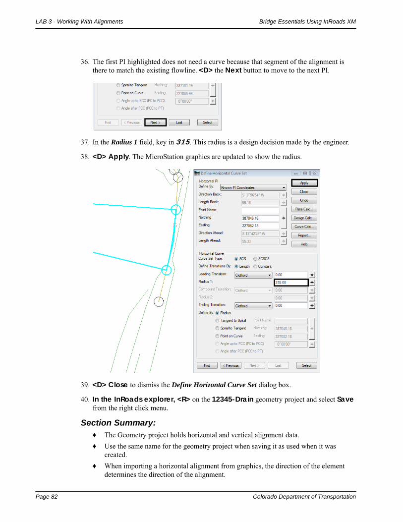
36. The first PI highlighted does not need a curve because that segment of the alignment is there to match the existing flowline. <D> the Next button to move to the next PI.
37. In the Radius 1 field, key in 315. This radius is a design decision made by the engineer.
38. <D> Apply. The MicroStation graphics are updated to show the radius.
39. <D> Close to dismiss the Define Horizontal Curve Set dialog box.
40. In the InRoads explorer, <R> on the 12345-Drain geometry project and select Save from the right click menu.
Section Summary:♦ The Geometry project holds horizontal and vertical alignment data.
♦ Use the same name for the geometry project when saving it as used when it was created.
♦ When importing a horizontal alignment from graphics, the direction of the element determines the direction of the alignment.

Colorado Department of Transportation Page 83
Bridge Essentials Using InRoads XM LAB 3 - Working With Alignments
Lab 3.3 - Creating a Vertical Alignment
A vertical alignment controls the elevation of the template as it is placed along the corridor. Vertical alignments are typically built in a profile window.
Section Objectives:
♦ Create a profile along the new horizontal alignment.
♦ Create a vertical alignment placeholder.
♦ Add data to the vertical alignment
In order to add data to a vertical alignment, a profile window is required.
1. From the MicroStation menu bar, select File > Open.
2. Navigate to the C:\Projects\12345\Bridge\Drawings\Reference Files\ folder and select the 12345BRDG_Prof.dgn file.
3. From the InRoads menu bar, select Evaluation > Profile > Create Profile.
4. In the Create Profile dialog box, <D> the Preferences button.
5. In the Preferences dialog box, select 10x Vertical.

Page 84 Colorado Department of Transportation
LAB 3 - Working With Alignments Bridge Essentials Using InRoads XM
6. <D> Load then <D> Close to dismiss the Preferences dialog box.
Using the 10x vertical exaggeration makes it easier to see elevation changes in relatively flat terrain.
7. Verify that the 12345_Drain surface is the only selected surface.
8. <D> Apply then <D> in the MicroStation view window. The profile is drawn in the dgn.
9. <D> Close to dismiss the Create Profile dialog box.
10. In MicroStation, zoom in on the profile so that the elevations between 4680 and 4700 are visible.
With the profile window created, the vertical alignment data can be entered. The first step in this process is to create a vertical alignment placeholder for the Channel_Flowline horizontal alignment.

Colorado Department of Transportation Page 85
Bridge Essentials Using InRoads XM LAB 3 - Working With Alignments
11. On the InRoads menu bar, select File > New.
12. In the New dialog box, <D> the Geometry tab.
13. Set the Type to Vertical Alignment.
14. Key in Channel_Flowline-V for the Name.
15. Set the Style to ALG_PRO_Vert.
16. <D> Apply then <D> Close to dismiss the New dialog box.
17. On the InRoads menu bar, select Geometry > Vertical Curve Set > Add PI.
18. In the Add Vertical PI dialog box, <D> the Add button.
Page 86 Colorado Department of Transportation
LAB 3 - Working With Alignments Bridge Essentials Using InRoads XM
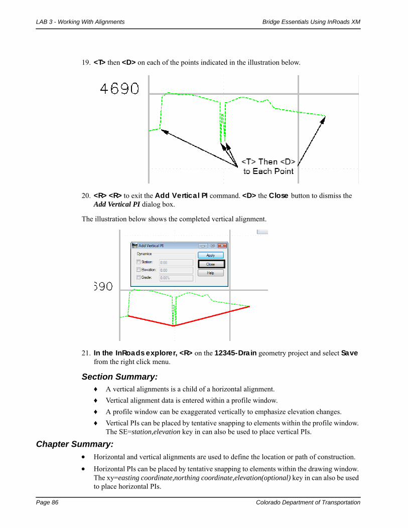
19. <T> then <D> on each of the points indicated in the illustration below.
20. <R> <R> to exit the Add Vertical PI command. <D> the Close button to dismiss the Add Vertical PI dialog box.
The illustration below shows the completed vertical alignment.
21. In the InRoads explorer, <R> on the 12345-Drain geometry project and select Save from the right click menu.
Section Summary:♦ A vertical alignments is a child of a horizontal alignment.
♦ Vertical alignment data is entered within a profile window.
♦ A profile window can be exaggerated vertically to emphasize elevation changes.
♦ Vertical PIs can be placed by tentative snapping to elements within the profile window. The SE=station,elevation key in can also be used to place vertical PIs.
Chapter Summary:
Horizontal and vertical alignments are used to define the location or path of construction.
Horizontal PIs can be placed by tentative snapping to elements within the drawing window. The xy=easting coordinate,northing coordinate,elevation(optional) key in can also be used to place horizontal PIs.

Colorado Department of Transportation Page 87
Bridge Essentials Using InRoads XM LAB 3 - Working With Alignments
A profile window displays the elevations of the existing ground under the horizontal alignment.
Profiled are the entry point for vertical alignment data.
Save the geometry project after data is entered. This file does not save automatically.

Page 88 Colorado Department of Transportation
LAB 3 - Working With Alignments Bridge Essentials Using InRoads XM