L2036H1 (031205c). Imaging No.: 031205c Sample: IDP (L2036H1) Beamline: BL47XU X-ray photon energy:...
14
L2036H1 (031205c)
-
Upload
coleen-murphy -
Category
Documents
-
view
214 -
download
0
Transcript of L2036H1 (031205c). Imaging No.: 031205c Sample: IDP (L2036H1) Beamline: BL47XU X-ray photon energy:...

L2036H1 (031205c)

L2036H1 (031205c)
Imaging No.: 031205cSample: IDP (L2036H1)Beamline: BL47XUX-ray photon energy: 7 keVExposure time for each projection: 1.5 sec.No. of pixels for each projection image: 256 × 140pels
No. of projection images for dark current : 2 (1 each before and after sample imaging)No. of projection images for incident beam current (I0): 151 (+1; for determining the rotation axis)No. of projection images for transmitted beam current (I): 750 (+1; ditto)Imaging sequence: One I0 imaging after every 5 I imagingPixel size of projection images: 0.5 micron
Voxel size of reconstructed CT images : 0.5 micronNo. of voxels : 256 × 256 × 140Location of sample rotation axis: 125.5 ( z = 0 - 139 )
Byte images:PV=0: CT value = 0 1/cmPV=400: CT value = 158.522730 1/cm
(theoretical LAC of enstatite)
Cut images: Threshold: PV=22Erosion: 3 layersDilation: 6 layers
Voxel size : 0.5 micronNumber of voxels : 68 × 71 × 93
TLI3 images: Interpolation: 3 ×3 ×3Voxel size : 0.1667 micronNumber of voxels : 204 × 213 × 278
cut/33.tif (width: 34 m)
0
1
2
3
4
5
6
0 50 100 150 200 250
byte_hst
log N
PV
PV=122(sample)
PV=39(glue)
PV=22(air-glue)PV=93(glue-sample)
TLI3/99.tif (width: 34 m)

L2036H1 (031205c) : browse image
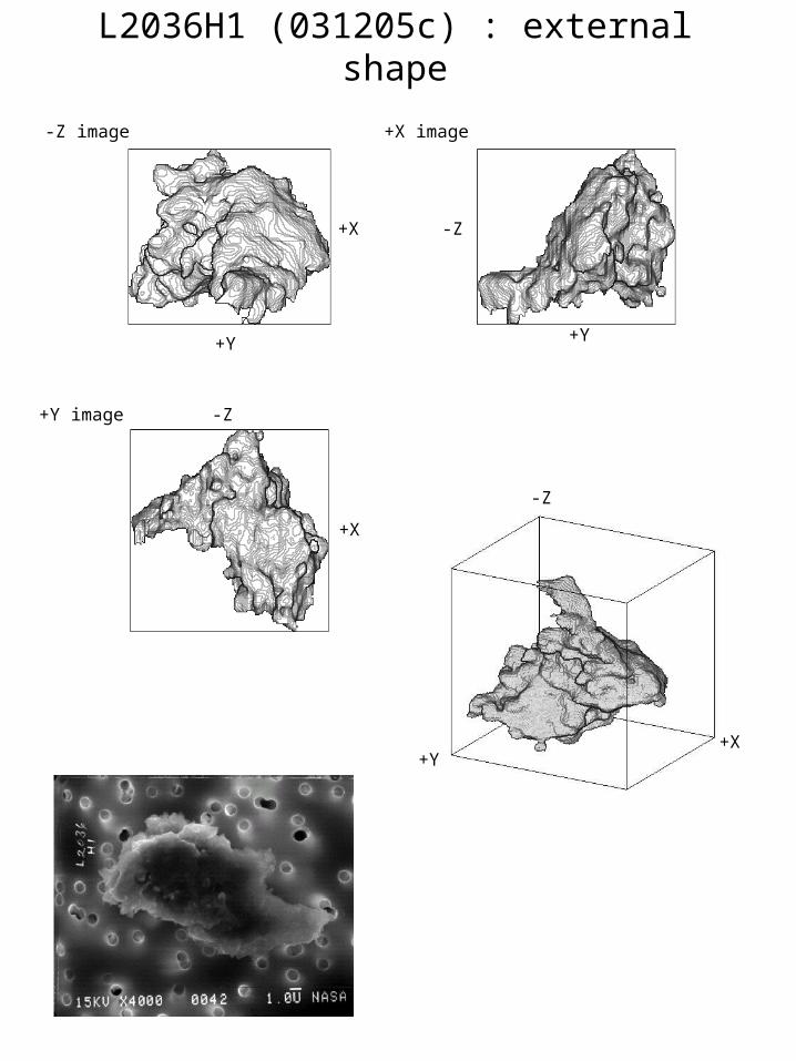
L2036H1 (031205c) : external shape
+X
+Y
-Z image
+Y
-Z
+X image
+X
-Z+Y image
-Z
+X+Y
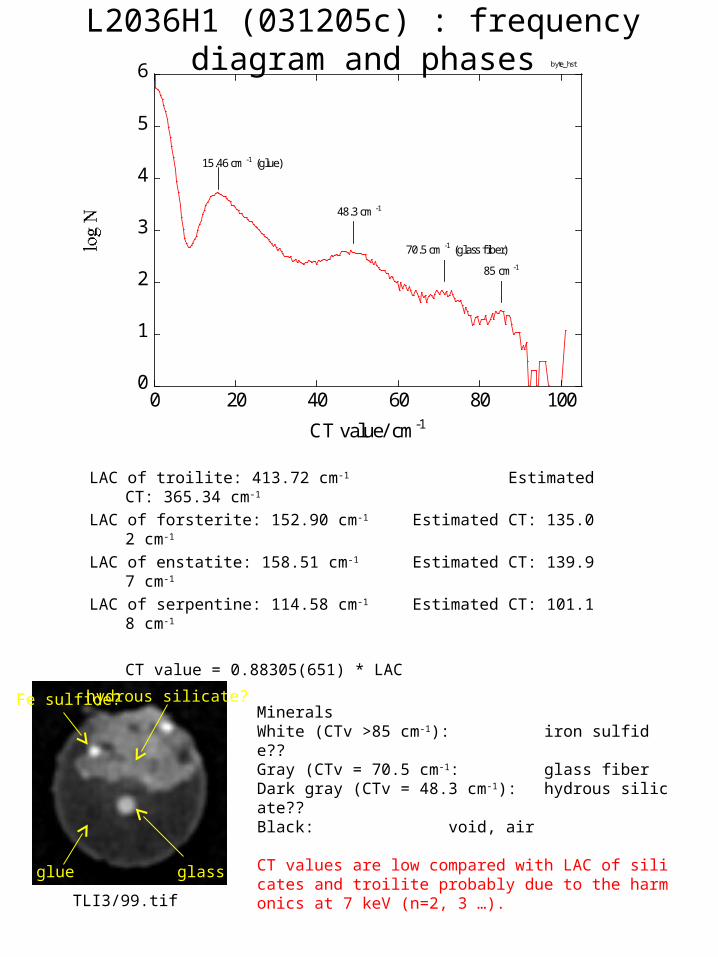
L2036H1 (031205c) : frequency diagram and phases
LAC of troilite: 413.72 cm-1 Estimated CT: 365.34 cm-1
LAC of forsterite: 152.90 cm-1 Estimated CT: 135.02 cm-1
LAC of enstatite: 158.51 cm-1 Estimated CT: 139.97 cm-1
LAC of serpentine: 114.58 cm-1 Estimated CT: 101.18 cm-1
CT value = 0.88305(651) * LAC
TLI3/99.tif
MineralsWhite (CTv >85 cm-1): iron sulfide??Gray (CTv = 70.5 cm-1: glass fiberDark gray (CTv = 48.3 cm-1): hydrous silicate??Black: void, air
CT values are low compared with LAC of silicates and troilite probably due to the harmonics at 7 keV (n=2, 3 …).
glue glass
hydrous silicate?Fe sulfide?
0
1
2
3
4
5
6
0 20 40 60 80 100
byte_hst
CT value/ cm-1
48.3 cm -1
15.46 cm -1 (glue)
70.5 cm -1 (glass fiber)
85 cm -1

L2036H1 (031205c): XRD (T.Nakamura et al.)

L2011Q5 (040615a)

L2011Q5 (040615a)
Imaging No.: 040615aSample: IDP (L2011Q5) hydrated IDPBeamline: BL20XUX-ray photon energy: 8 keVExposure time for each projection: 1 sec.No. of pixels for each projection image: 256 × 170 pels
No. of projection images for dark current : 2 (1 each before and after sample imaging)No. of projection images for incident beam current (I0): 76 (+1; for determining the rotation axis)No. of projection images for transmitted beam current (I): 750 (+1; ditto)Imaging sequence: One I0 imaging after every 10 I imagingPixel size of projection images: 0.23 micron
Voxel size of reconstructed CT images : 0.23 micronNo. of voxels : 256 × 256 × 170Location of sample rotation axis: ( z = 0 - 169 )
Byte images:PV=0: CT value = 0 1/cmPV=100: CT value = 103.982481 1/cm
(theoretical LAC of forsterite)
Cut images: Threshold: PV=44Erosion: 3 layersDilation: 6 layers
Voxel size : 0.23 micronNumber of voxels : 133 × 147 × 149
cut/67.tif (width: 30.59 m)
1
2
3
4
5
6
0 50 100 150 200 250
byte_hstlog N
PV
PV=120(sample)PV=50(glue)
PV=44(air-glue)PV=77(glue-sample)

L2011Q5 (040615a) : browse image

L2011Q5 (040615a) : external shape
+X
+Y
-Z image
+Y
-Z
+X image
+X
-Z+Y image
-Z
+X+Y

L2011Q5 (040615a) : frequency diagram and phases
LAC of magnetite: 1105.54 cm-1 Estimated CT: 972 cm-1
LAC of forsterite: 103.94 cm-1 Estimated CT: 91 cm-1
LAC of serpentine: 76.07 cm-1 Estimated CT: 67 cm-1
CT value = 0.88 * LAC
MineralsWhite (CTv <300 cm-1): magnetite?Gray (CTv = 120-130 cm-1): hydrous silicate?Dark gray (CTv = 52 cm-1): glueBlack: void, air
CT values are low compared with LAC of silicates and troilite probably due to the harmonics at 8 keV (n=2, 3 …).
glue glass
hydrous silicate?
magnetite?
1
2
3
4
5
6
0 50 100 150 200 250
byte_hst
CT value /cm-1
124.8 cm -152.0 cm -1 (glue)
cut/67.tif (width: 30.59 m)
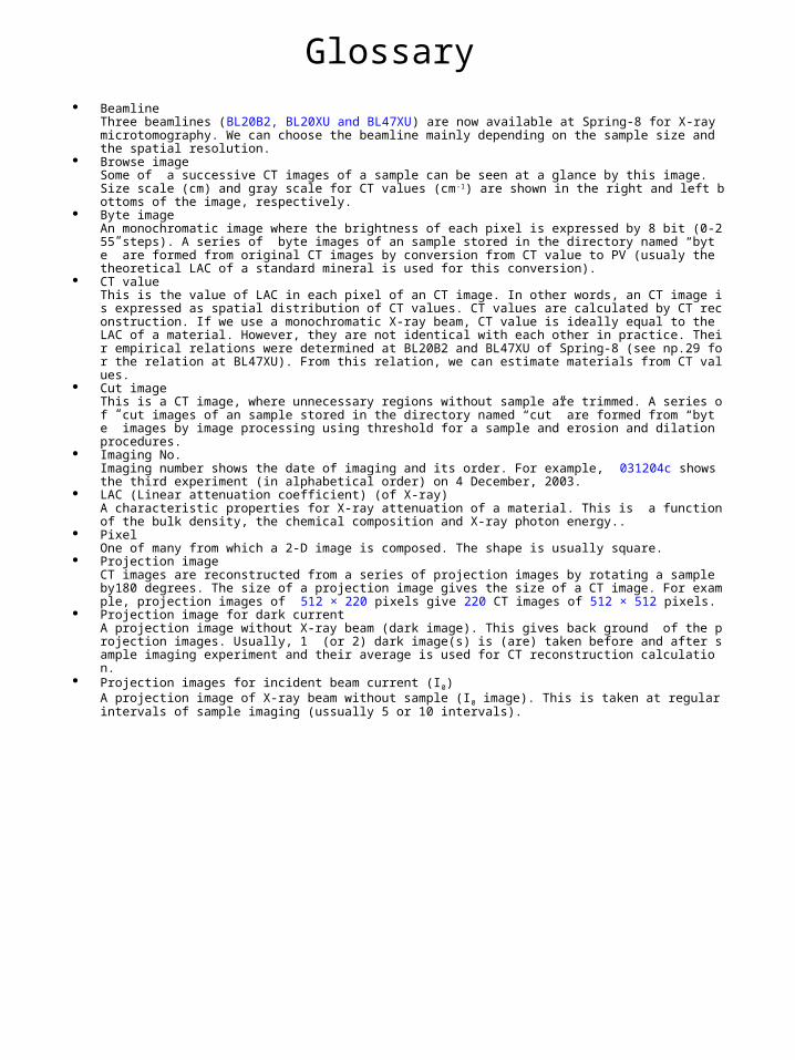
Glossary Beamline
Three beamlines (BL20B2, BL20XU and BL47XU) are now available at Spring-8 for X-ray microtomography. We can choose the beamline mainly depending on the sample size and the spatial resolution.
Browse imageSome of a successive CT images of a sample can be seen at a glance by this image. Size scale (cm) and gray scale for CT values (cm-1) are shown in the right and left bottoms of the image, respectively.
Byte imageAn monochromatic image where the brightness of each pixel is expressed by 8 bit (0-255 steps). A series of byte images of an sample stored in the directory named “byte” are formed from original CT images by conversion from CT value to PV (usualy the theoretical LAC of a standard mineral is used for this conversion).
CT valueThis is the value of LAC in each pixel of an CT image. In other words, an CT image is expressed as spatial distribution of CT values. CT values are calculated by CT reconstruction. If we use a monochromatic X-ray beam, CT value is ideally equal to the LAC of a material. However, they are not identical with each other in practice. Their empirical relations were determined at BL20B2 and BL47XU of Spring-8 (see np.29 for the relation at BL47XU). From this relation, we can estimate materials from CT values.
Cut imageThis is a CT image, where unnecessary regions without sample are trimmed. A series of cut images of an sample stored in the directory named “cut” are formed from “byte” images by image processing using threshold for a sample and erosion and dilation procedures.
Imaging No.Imaging number shows the date of imaging and its order. For example, 031204c shows the third experiment (in alphabetical order) on 4 December, 2003.
LAC (Linear attenuation coefficient) (of X-ray)A characteristic properties for X-ray attenuation of a material. This is a function of the bulk density, the chemical composition and X-ray photon energy..
PixelOne of many from which a 2-D image is composed. The shape is usually square.
Projection imageCT images are reconstructed from a series of projection images by rotating a sample by180 degrees. The size of a projection image gives the size of a CT image. For example, projection images of 512 × 220 pixels give 220 CT images of 512 × 512 pixels.
Projection image for dark currentA projection image without X-ray beam (dark image). This gives back ground of the projection images. Usually, 1 (or 2) dark image(s) is (are) taken before and after sample imaging experiment and their average is used for CT reconstruction calculation.
Projection images for incident beam current (I0)A projection image of X-ray beam without sample (I0 image). This is taken at regular intervals of sample imaging (ussually 5 or 10 intervals).

Coordination system
Projection images for transmitted beam current (I)A projection image of sample (I image). The projection , p=ln(I0/I), is calculated and used for CT reconstruction.
Sample rotation axisThe location of a sample rotation axis is required for CT reconstruction. This is called “center value”, which is generally described as a function of the height of a projection image (z: see the coordinate system). For example, the center value is expressed as follows: 249.934 -0.003046 × z ±0.320748( z = 0 - 219) .
PV (Pixel value)This is the value that expresses the brightness of each pixel of a digital image. For example, the pixel is black and white for PV=0 and 255, respectively, in a byte image.
VoxelOne of many from which a 3-D image is composed. The shape is usually cubic.
+X
+Y
+Z
(0,0,0)
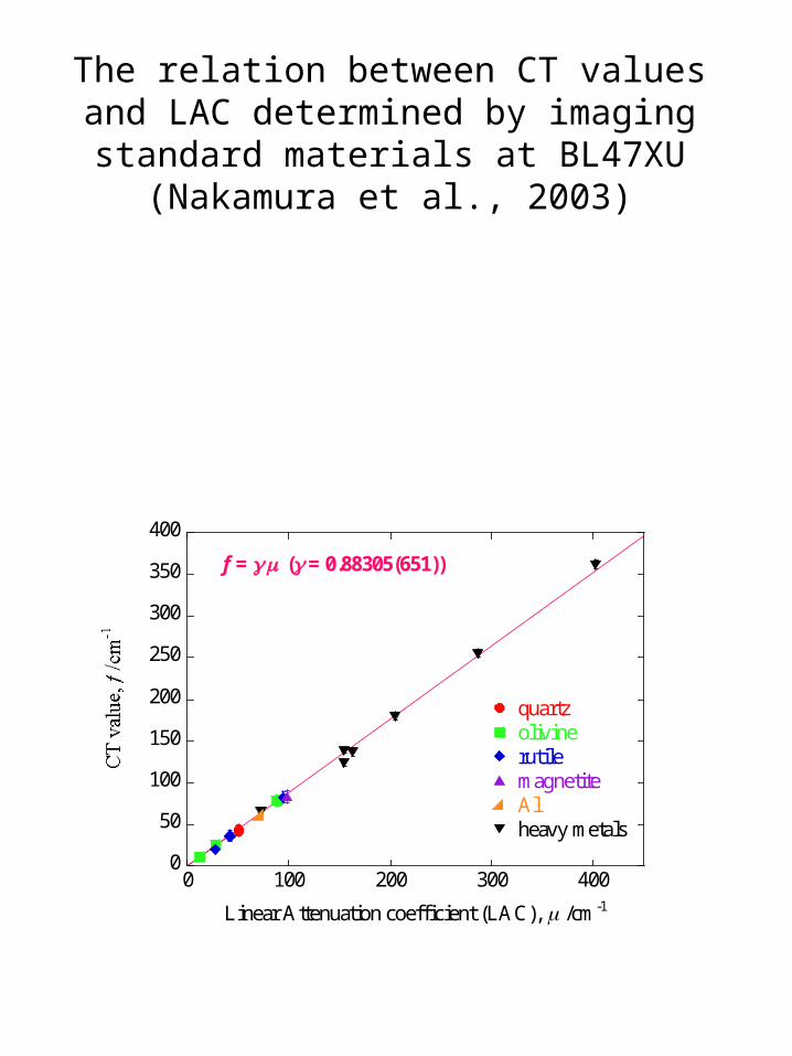
The relation between CT values and LAC determined by imaging standard materials at
BL47XU (Nakamura et al., 2003)
0
50
100
150
200
250
300
350
400
0 100 200 300 400
quartzolivinerutilemagnetiteAlheavy metals
Linear Attenuation coefficient (LAC), /cm-1
f = ( = 0.88305(651))