1 Beamline DayTimePresenterTopic Thurs9:00C.BoothMICE Target Wed16:00K.TilleyRecent Beamline Design...
27
1 Beamlin e Day Time Presenter Topic Thurs 9:00 C.Booth MICE Target Wed 16:00 K.Tilley Recent Beamline Design Work Wed 16:30 T.Roberts MICE Beamline Performance + Emittance Analysis MICE Collaboration Meeting, RAL, Oct2004
-
Upload
byron-dawson -
Category
Documents
-
view
229 -
download
0
Transcript of 1 Beamline DayTimePresenterTopic Thurs9:00C.BoothMICE Target Wed16:00K.TilleyRecent Beamline Design...

1
Beamline
Day Time Presenter Topic
Thurs 9:00 C.Booth MICE Target
Wed 16:00 K.Tilley Recent Beamline Design Work
Wed 16:30 T.Roberts MICE Beamline Performance + Emittance Analysis
MICE Collaboration Meeting, RAL, Oct2004

Status of Target Design
Chris Booth
Sheffield
28th October 2004

Diaphragm spring
Target
Array of coils Magnet(s)
Position measurement
Schematic design
Linear Drive

Draft Specification• Transit: 40 mm
• Entry ≥ 5 mm into beam in ≤ 2 ms(see plot)
• Cycle time: 20 ms
• Positioning accuracy: 0.5 mm
• Timing accuracy: ~ 0.2 ms
• Frequency: (baseline) 1 to 3 Hz on demand
• (optimal) 1 to 50 Hz
• Maximum proton rate: 1.41012 per second
• Must operate in vacuum and radiation environment
• Must not interfere with ISIS operation!!

Target edge trajectoryWith spring
45
50
55
60
65
70
75
80
0 5 10 15 20 25 30
t (ms)
Posi
tion
(mm
)
beam
target
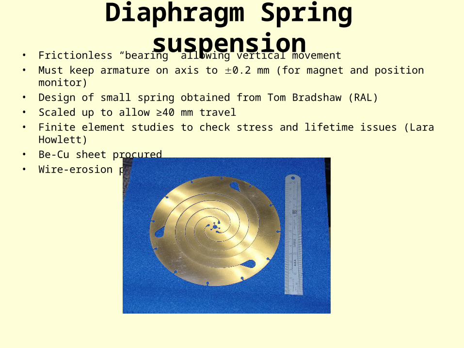
Diaphragm Spring suspension• Frictionless “bearing” allowing vertical movement• Must keep armature on axis to 0.2 mm (for magnet and position monitor)• Design of small spring obtained from Tom Bradshaw (RAL)• Scaled up to allow ≥40 mm travel• Finite element studies to check stress and lifetime issues (Lara Howlett)• Be-Cu sheet procured• Wire-erosion performed in Eng. Dept. workshop

Linear Drive (1)• Tests with first prototype
– Moving magnet shuttle (2 magnets)– Static single/double coil excitation– No commutator
~ radial field
S N N S
(Armature)

…however!• Current armature/coil design does not give required
acceleration
– 280 N kg–1 at 20 A mm–2
– Need ~950 N kg–1
revised armature design current density 35 A mm–2 for short pulses. Thus
effective cooling essential (proposing placing coils in conductive resin, surrounded by water cooling jacket…)

Improved armature design
soft iron Nd-Fe-B magnets
Sectored magnets – fixed together with aircraft glue
Also, other materials eg. SmCo?

x o o x o o
Coils
Armature
o x x o x x
x o o x o o
x o o x o o
Coils
Armature
o o x o o x
x x o x x o
“3-phase” drive
x o o x o o
Coils
Armature
x o x x o x
o x o o x o
x o o x o o
Coils
Armature
x o o x o o
o x x o x x
1 3
42
Magnetic actuator plus Hall switches bipolar drive

Radiation concerns• Studying documented radiation hardnesses
of target systems/components
• expected to be dominated by beam loss
produced during target insertion
• hope to make measurements at ISIS in
spring

Plans for next months• Complete revised design
- Optimised coil, armature design
- 3-phase switched drive circuit
• Currently mounting 1st prototype vertically on diaphragm springs
- Measure lateral stability
- Debug position readout system, check read speed
- Develop cooling and temperature measurement system
- Switch to new drive as soon as available
• Develop control hardware & software

paul drumm, mutac jan 2003 13
Recent Beamline Design Work
Kevin Tilley , ISIS , RAL
• Recent beamline revisions
• Description of SEPT04 beamline design
• Aims
• Calculation of beam momentas
• Envelopes and assessment with Turtle
• Future Plans
1

paul drumm, mutac jan 2003 14
Recent Design Revisions
JAN04 → first, new design concept
(JAN04A → lower emittance, higher Good Mu rate example)
MAR04 → Realistic geometry/constraints, C2H4 Mu purity
JUNE04 → Modified for correct definition
(JUNE04A → proposed chgs to lower TOF0, incr Good Mu)
… to Current work -
2
radmmyn 6,

paul drumm, mutac jan 2003 15
Motivations for new design - SEPT04
• To reduce muon design momentum from 236 → 206MeV/c
• Maintain (usual cut)
whilst at the same time, set the design for:-
• Low TOF0 singles rate
• High Good-muon rate.
radmmyn 6,
3

paul drumm, mutac jan 2003 16
Muon Momenta's
Defining the beamline momentums
For at 206MeV/c at exit of Pb, working backwards through the Pb and the C2H4 gives a value of 233MeV/c needed after the decay solenoid. [NB energy loss due to PIDs etc not included]
radmmyn 6,
4
Pion Momentum
For both a lower TOF0 singles rate, and for a high intensity final muon beam, we can use the high intensity working point relation from similar beamlines (PSI uE1/uE4 & RAL-RIKEN): -> 390MeV/c
Graph taken from PSI,SIN Users Handbook
yx ,

paul drumm, mutac jan 2003 17
Results of Optics work (Pi+Decay Sectn)
7
Q1'
Q2'
Q3'Q1 Q2 Q3 B1 Solenoid
Vertical Half-width
(cm)
HorizontalHalf-width
(cm)
25
0
25
16mz
Q1'
Q2'
Q3'
Q1'
Q2'
Q3'
Q1'
Q2'
Q3'Q1 Q2 Q3 B1 Solenoid
Vertical Half-width
(cm)
HorizontalHalf-width
(cm)
25
0
25
16mz
Now 3.7Tesla
• Full width beam profile
• Shows p0 @390Mev/c

paul drumm, mutac jan 2003 18
B2
Q4
Q5
Q6
Q7
Q8
Q9
PbPT
B1B2 Q4 Q5 Q6 Q7 Q9Q8
Pb.Disk
Vertical Half-width
(cm)
HorizontalHalf-width
(cm)
25
0
25
16mz
B2
Q4
Q5
Q6
Q7
Q8
Q9
PbPT
B1B2 Q4 Q5 Q6 Q7 Q9Q8
Pb.Disk
Vertical Half-width
(cm)
HorizontalHalf-width
(cm)
25
0
25
B2
Q4
Q5
Q6
Q7
Q8
Q9
PbPT
B1B2 Q4 Q5 Q6 Q7 Q9Q8
Pb.Disk
Vertical Half-width
(cm)
HorizontalHalf-width
(cm)
25
0
25
16mz
Results of Optics work (Muon Extraction)
• RMS beam profile
• Shows p0 @220Mev/c
• Showing yx
8
paul drumm, mutac jan 2003 19
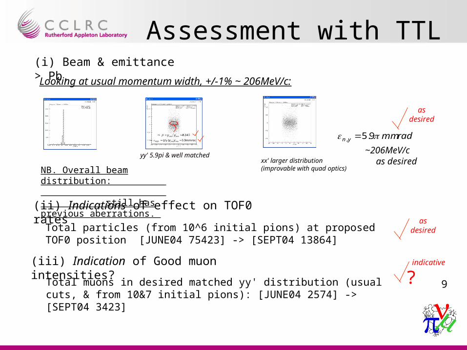
Assessment with TTL
Looking at usual momentum width, +/-1% ~ 206MeV/c:
(i) Beam & emittance > Pb.
xx' larger distribution (improvable with quad optics)
yy' 5.9pi & well matched~206MeV/c
347.0' rmsrms yy
mmradyy rmsrmsRQD 9.5)( ' radmmyn 9.5,
NB. Overall beam distribution: still has previous aberrations.
9
(ii) Indications of effect on TOF0 rates
Total particles (from 10^6 initial pions) at proposed TOF0 position [JUNE04 75423] -> [SEPT04 13864]
(iii) Indication of Good muon intensities?
Total muons in desired matched yy' distribution (usual cuts, & from 10&7 initial pions): [JUNE04 2574] -> [SEPT04 3423]
?
as desired
indicative
as desired
as desired
paul drumm, mutac jan 2003 20
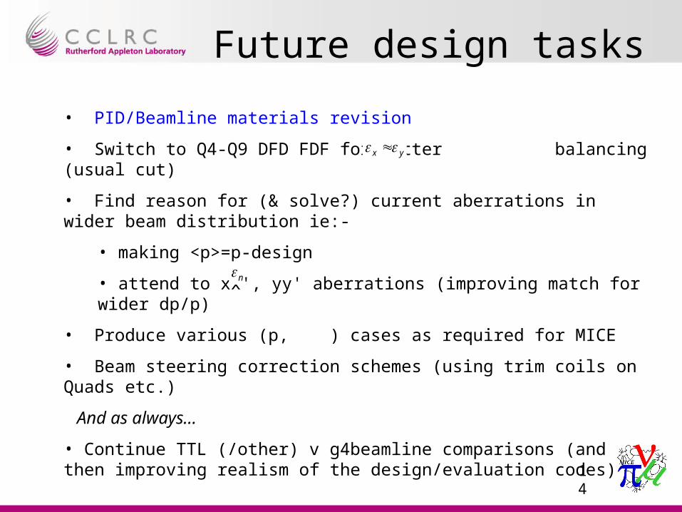
Future design tasks
• PID/Beamline materials revision
• Switch to Q4-Q9 DFD FDF for better balancing (usual cut)
• Find reason for (& solve?) current aberrations in wider beam distribution ie:-
• making <p>=p-design
• attend to xx', yy' aberrations (improving match for wider dp/p)
• Produce various (p, ) cases as required for MICE
• Beam steering correction schemes (using trim coils on Quads etc.)
And as always…
• Continue TTL (/other) v g4beamline comparisons (and then improving realism of the design/evaluation codes)
yx
n
14

MICE Beamline Performance & Emittance Analysis
Tom RobertsMuons, Inc.
October 27, 2004

Summary of this Simulation
• The SEPT04 magnet currents/positions (optics) but also:– First guess of the beamline vacuum, windows, air
gaps. Also inclusion of PID materials in beamline.• More detailed implementation of Tracker1 and Tracker2
– Vacuum with windows– 5 planes, 1.5 mm scintillator each, located as in the
TRD• TRD configurations for everything except a few minor
things (absorber and RF window shapes, RF Cavity size, Cherenkov2 modeled as a circle)

The additional effect of the vacuum windows, air gaps & PID materials in this simulation.
μ+ central momentum in Tracker1 – design 206 MeV/c
μ+ central momentum in Tracker1 – achieved 183 MeV/c
This highlights the potential for further differences, betweenthe design goals and the results of this current simulation.

Summary of Rates
Description LAHET MARS Geant4
TOF0 2173 2676 2548
TOF1 513 631 601
Tracker1 462 569 542
Tracker2 343 442 402
TOF2 339 418 398
Good μ+ 336 414 394
Values are events per millisecond of Good Target and good RF.
Good μ+ = TargetDet & TOF0 & TOF1 & Tracker1 & Tracker2 & TOF2 & TOF1(μ+) & TOF2(μ+)

Emittance Computation - method
• SEPT04 beamline optics + PIDs, air & vacuum windows• Absorbers are empty, no RF• Analysis chain: g4beamline → for009sum → ecalc9f → excel• for009sum combines multiple FOR009.DAT files, and imposes cuts:
– Require through tracks (hits in all 10 Tracker stations)– Ptot cut, applied in the first region (Tracker1a)
• All cuts in ecalc9f are disabled (except PID), so the only cuts are:– Require each track to be a μ+ in all 10 Tracker stations– Require through tracks (hits in all 10 Tracker stations)– Ptot cut in Tracker1a (+/-5MeV/c ~ momentum of interest)
• A shell script was used to automate the interface to ecalc9f and connect the analysis chain together

Emittance Computation
Transverse Emittance in various Ptot bins
0
2
4
6
8
10
12
29 30 31 32 33 34 35 36 37 38 39 40 41 42
Position along Z (meters from ISIS Target)
Ep
erp
(m
m r
ad
) 165 MeV/c
175 MeV/c
185 MeV/c
195 MeV/c
205 MeV/c
215 MeV/c
Emittance @ 205MeV/c ≈ 8.2 pi mm rad

Conclusions
• The SEPT04 beamline optics were assessed, adding also the PIDs, air & vacuum windows in this simulation.
• TOF0 rates are lower than JUNE04 at ~ 2.5MHz
• The Good muon count is comparable to JUNE04.
• In this analysis, the input emittance for the bin +/-5MeV/c
about 205MeV/c is ~ 8.2 pi mm rad.
• The transverse emittance computed here increases in the empty cooling channel, at all momentums considered.
• A further beamline optics which accounts fully for the PID, air & vacuum windows should be produced and re-evaluated.