L07 - Integrated Motion on EtherNetIP Lab · following Axis01 but at approximately half the speed....
58
L07 - Integrated Motion on Ethernet/IP – Basic Lab For Classroom Use Only!
Transcript of L07 - Integrated Motion on EtherNetIP Lab · following Axis01 but at approximately half the speed....

L07 - Integrated Motion on Ethernet/IP – Basic Lab
For Classroom Use Only!

Important User Information
This documentation, whether, illustrative, printed, “online” or electronic (hereinafter “Documentation”) is intended for use only as a learning aid when using Rockwell Automation approved demonstration hardware, software and firmware. The Documentation should only be used as a learning tool by qualified professionals. The variety of uses for the hardware, software and firmware (hereinafter “Products”) described in this Documentation, mandates that those responsible for the application and use of those Products must satisfy themselves that all necessary steps have been taken to ensure that each application and actual use meets all performance and safety requirements, including any applicable laws, regulations, codes and standards in addition to any applicable technical documents. In no event will Rockwell Automation, Inc., or any of its affiliate or subsidiary companies (hereinafter “Rockwell Automation”) be responsible or liable for any indirect or consequential damages resulting from the use or application of the Products described in this Documentation. Rockwell Automation does not assume responsibility or liability for damages of any kind based on the alleged use of, or reliance on, this Documentation. No patent liability is assumed by Rockwell Automation with respect to use of information, circuits, equipment, or software described in the Documentation.
Except as specifically agreed in writing as part of a maintenance or support contract, equipment users are responsible for:
• properly using, calibrating, operating, monitoring and maintaining all Products consistent with all Rockwell Automation
or third-party provided instructions, warnings, recommendations and documentation;
• ensuring that only properly trained personnel use, operate and maintain the Products at all times;
• staying informed of all Product updates and alerts and implementing all updates and fixes; and • all other factors affecting the Products that are outside of the direct control of Rockwell Automation.
Reproduction of the contents of the Documentation, in whole or in part, without written permission of Rockwell Automation is prohibited. Throughout this manual we use the following notes to make you aware of safety considerations:
Identifies information about practices or circumstances that can cause an explosion in a hazardous environment, which may lead to personal injury or death, property damage, or economic loss.
Identifies information that is critical for successful application and understanding of the product.
Identifies information about practices or circumstances that can lead to personal injury or death, property damage, or economic loss. Attentions help you: • identify a hazard • avoid a hazard • recognize the consequence
Labels may be located on or inside the drive to alert people that dangerous voltage may be present.
Labels may be located on or inside the drive to alert people that surfaces may be dangerous temperatures.
3 of 58
Integrated Motion on Ethernet/IP – Basic Lab
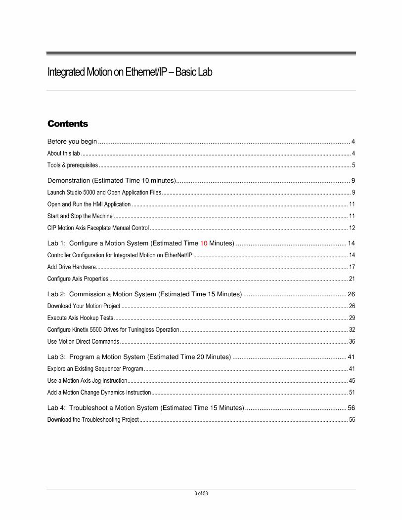
Contents
Before you begin ........................................................................................................................................... 4
About this lab .................................................................................................................................................................................... 4
Tools & prerequisites ........................................................................................................................................................................ 5
Demonstration (Estimated Time 10 minutes)................................................................................................ 9
Launch Studio 5000 and Open Application Files .............................................................................................................................. 9
Open and Run the HMI Application ................................................................................................................................................ 11
Start and Stop the Machine ............................................................................................................................................................ 11
CIP Motion Axis Faceplate Manual Control .................................................................................................................................... 12
Lab 1: Configure a Motion System (Estimated Time 10 Minutes) ............................................................. 14
Controller Configuration for Integrated Motion on EtherNet/IP ....................................................................................................... 14
Add Drive Hardware ........................................................................................................................................................................ 17
Configure Axis Properties ............................................................................................................................................................... 21
Lab 2: Commission a Motion System (Estimated Time 15 Minutes) ......................................................... 26
Download Your Motion Project ....................................................................................................................................................... 26
Execute Axis Hookup Tests ............................................................................................................................................................ 29
Configure Kinetix 5500 Drives for Tuningless Operation ................................................................................................................ 32
Use Motion Direct Commands ........................................................................................................................................................ 36
Lab 3: Program a Motion System (Estimated Time 20 Minutes) ............................................................... 41
Explore an Existing Sequencer Program ........................................................................................................................................ 41
Use a Motion Axis Jog Instruction ................................................................................................................................................... 45
Add a Motion Change Dynamics Instruction ................................................................................................................................... 51
Lab 4: Troubleshoot a Motion System (Estimated Time 15 Minutes) ........................................................ 56
Download the Troubleshooting Project ........................................................................................................................................... 56

4 of 58
Before you begin
Prerequisite is to be familiar with Logix Designer software and programming. When the computer is booted, a FactoryTalk View
ME Station program will start. You will use that Human Machine Interface (HMI) throughout the lab. If you close it at any time,
you will need to open it again from the Lab Files folder on the desktop in order to operate the lab correctly.
About this lab
You will be introduced to Logix Designer software environment as the single software tool used by the Rockwell Automation
Integrated Motion Solution for configuration, commissioning, programming, and troubleshooting. You will also experience the
inherent ease with which you can define your motion process.
You will see how easy it is to create an Integrated Motion Solution as you do the following:
� Create and configure motion axes using Logix Designer
� Learn basic motion-direct commands to simplify commissioning
� Configure the tuningless features for the Kinetix 5500 drives
� Learn some basic troubleshooting techniques
This lab takes approximately 70 minutes to complete.

5 of 58
Tools & prerequisites
For this hands-on lab, we have provided you with the following materials that will allow you to complete the labs in this workbook.
Software
� Logix Designer v30.00
� FactoryTalk View ME Station v9.00
� RSLinx Classic v3.90.00
Hardware
� Computer with Windows 10 operating system
� CompactLogix 1769-L36ERM Demo (DEMO-CMXL361)
� Kinetix 5500 3-axis Demo w/ PowerFlex 527 (09P096G)
� Ethernet Patch Cables
� 3 x RJ45 to RJ45 (2m length)
� 2 x RJ45 to RJ45 (1m length)
Required Files
� Demo_Integ_Motion.ACD
� Integ_Motion_K5500_PF527_ViewME.MER
� Lab_1_Integ_Motion_Configure.ACD
� Lab_2_Integ_Motion_Commission.ACD
� Lab_3_Integ_Motion_Program.ACD
� Lab_4_Integ_Motion_Troubleshoot.ACD
� Rung_3_Import.L5X
Optional Files
� Sample_MCD_Import.L5X
� Lab_4_SOLUTIONS.pdf
� Tuningless Features for the Kinetix 5000 Servo Drive Family.pdf

6 of 58
Network Setup
This is the recommended configuration for the lab, however due to the variable nature of EtherNet/IP topologies, many other
configurations will also work.
Ethernet Cable Routing:
Ethernet IP Addresses:
Computer 192.168.1.1
CompactLogix Processor 192.168.1.12
POINT I/O Ethernet Adapter 192.168.1.8
ArmorBlock Input Module 192.168.1.9 (not used)
ArmorBlock Output Module 192.168.1.10 (not used)
Kinetix 5500 Drive01 192.168.1.24
Kinetix 5500 Drive02 192.168.1.25
PowerFlex 527 Drive03 192.168.1.26
For the remainder of the basic lab
� Drive01 and Axis01 will refer to the Kinetix 5500 drive on the left side in the demo case.
� Drive02 and Axis02 will refer to the Kinetix 5500 on the right side in the demo case.
� Drive03 and Axis03 will refer to the PowerFlex 527 AC drive to the left of the Kinetix 5500s.
1 Ethernet Switch, Port 1 to Computer
2 Ethernet Switch, Port2 to Processor, Port 1
3 Processor, Port 2 to POINT I/O, Port 2
4 POINT I/O, Port 1 To Kinetix 5500 Drive 02, Port 2
5 Kinetix 5500 Drive 02, Port 1 To Kinetix 5500 Drive 01, Port 2
6 Kinetix 5500 Drive 01, Port 1 To PF527 Drive 03, Port 2

7 of 58
About the CompactLogix Demo
Use the image provided to locate these items on the demo and verify the lab setup:
� Verify the demo power switch labeled “120/220V” is “on”.
� Verify the circuit breaker is “on”.

8 of 58
About the Kinetix 5500 and PF527 3-Axis Demo
Use the image provided above to locate these items on the demo and verify the lab setup.
� Verify that the demo power switch is “on”.
� Verify that the circuit breaker is “on”.
� Verify that the switch labeled “K5500 DRIVE POWER” is “on”.
� Verify that the switch labeled “PF525 DRIVE POWER” is “on”. (Replaced with a PF527)
� Verify that the red mushroom button labeled “SAFE OFF” is pulled “out”.
9 of 58
Demonstration (Estimated Time 10 minutes)
Before starting the formal lab, let’s begin with a brief demonstration showing a completed file. During the demonstration, you will
be able to control a complete 3 axis solution with an HMI. Following the demonstration, you will move into the formal lab where
you will learn how to configure, commission, program, and troubleshoot a motion system with detailed step-by-step directions.
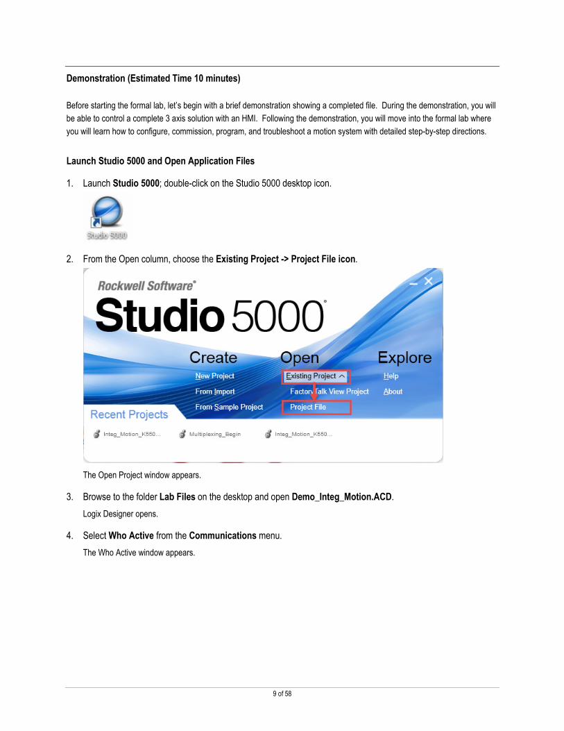
Launch Studio 5000 and Open Application Files
1. Launch Studio 5000; double-click on the Studio 5000 desktop icon.
2. From the Open column, choose the Existing Project -> Project File icon.
The Open Project window appears.
3. Browse to the folder Lab Files on the desktop and open Demo_Integ_Motion.ACD.
Logix Designer opens.
4. Select Who Active from the Communications menu.
The Who Active window appears.
10 of 58
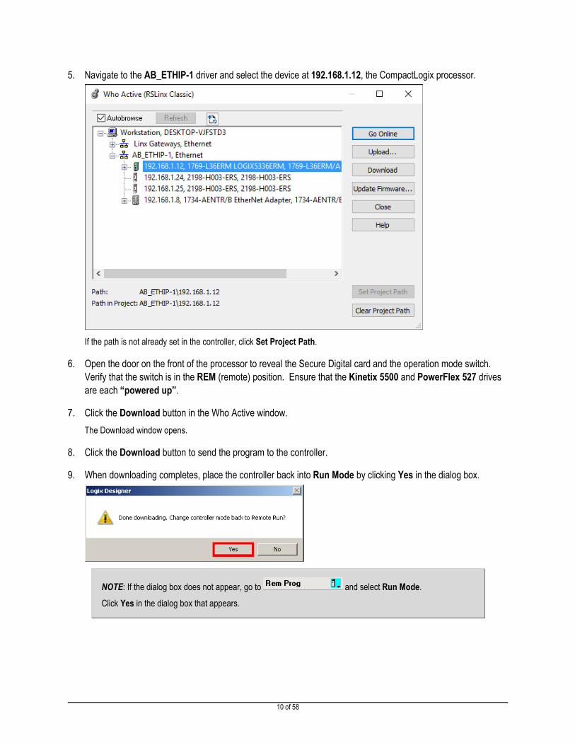
5. Navigate to the AB_ETHIP-1 driver and select the device at 192.168.1.12, the CompactLogix processor.
If the path is not already set in the controller, click Set Project Path.
6. Open the door on the front of the processor to reveal the Secure Digital card and the operation mode switch.
Verify that the switch is in the REM (remote) position. Ensure that the Kinetix 5500 and PowerFlex 527 drives
are each “powered up”.
7. Click the Download button in the Who Active window.
The Download window opens.
8. Click the Download button to send the program to the controller.
9. When downloading completes, place the controller back into Run Mode by clicking Yes in the dialog box.
NOTE: If the dialog box does not appear, go to and select Run Mode.
Click Yes in the dialog box that appears.

11 of 58
10. Verify that the controller is “communicating”.
� OK indicator should be solid green.
� LINK1 indicator should be flashing green, indicating network activity
� LINK2 indicator should be flashing green, indicating network activity
11. Verify that the drives are “ready”.
� Module light should be solid green.
� Network light should be solid green.
� The Kinetix 5500 and PF527 drives should read “STOPPED” across their display screen.
It may take a moment for the drives to reach these states. If any of the above steps did not work as described, please
consult your lab instructor.
Open and Run the HMI Application
1. Minimize Logix Designer so that the HMI screen on the desktop can be seen.
2. Click Start The Lab on the screen of the HMI to load the Startup screen.
3. The Startup screen should initially be displayed.
Start and Stop the Machine
1. If the machine is currently in the ABORTED state…
… press Clear Faults.
After a few moments the machine should transition to the STOPPED state.
12 of 58
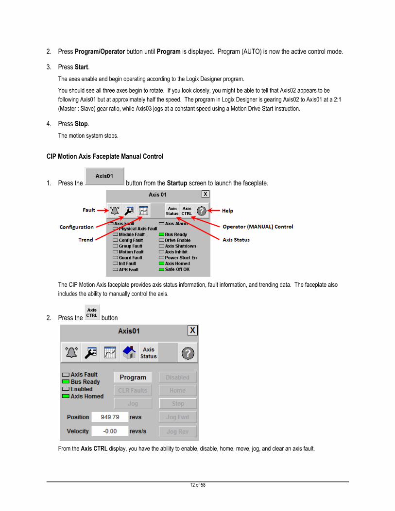
2. Press Program/Operator button until Program is displayed. Program (AUTO) is now the active control mode.
3. Press Start.
The axes enable and begin operating according to the Logix Designer program.
You should see all three axes begin to rotate. If you look closely, you might be able to tell that Axis02 appears to be
following Axis01 but at approximately half the speed. The program in Logix Designer is gearing Axis02 to Axis01 at a 2:1
(Master : Slave) gear ratio, while Axis03 jogs at a constant speed using a Motion Drive Start instruction.
4. Press Stop.
The motion system stops.
CIP Motion Axis Faceplate Manual Control
1. Press the button from the Startup screen to launch the faceplate.
The CIP Motion Axis faceplate provides axis status information, fault information, and trending data. The faceplate also
includes the ability to manually control the axis.
2. Press the button
From the Axis CTRL display, you have the ability to enable, disable, home, move, jog, and clear an axis fault.

13 of 58
3. Press the Program/Operator button so that Operator is displayed. Operator (MANUAL) mode is now the active
control mode.
4. Press the Enabled/Disabled button so that Enabled is displayed.
The axis will now be enabled and the Enabled indicator light will transition to solid green.
5. Press the Jog/Move button to select between the 2 types of manual control.
6. To set to jog speed, click on the corresponding Jog Spd display box to launch the keypad.
The units for both Jog and Move manual control are in revolutions or ‘revs’ and ‘revs/sec’.
NOTE: Some of the numbers shown are both indicators and keypad input buttons. For example, the Jog Spd indicator displays the actual speed feedback of the drive, not the desired jog speed. However, by clicking the indicator you launch the keypad input object where you can enter the desired jog speed.
7. Take a few minutes to manually control the axis by executing a Jog command. To move the axis, press and
hold the Jog Fwd or Jog Rev buttons.
8. This concludes the demonstration.
� When you are finished manually controlling the axes, be sure to Stop and Disable all of the drives.
� Maximize Logix Designer, and go offline with the current file by selecting Go Offline from the Communications menu.

14 of 58
Lab 1: Configure a Motion System (Estimated Time 10 Minutes)
In this lab, we will introduce you to the CompactLogix programmable automation controller, the Kinetix 5500 servo drive, and the
Logix Designer interface by stepping you through the configuration of a motion system.
Controller Configuration for Integrated Motion on EtherNet/IP
You will begin by configuring the CompactLogix controller for Integrated Motion on EtherNet/IP.
1. In Logix Designer, click Open in the File menu.
The Open window appears. You do not need to save changes to your existing file.
2. Browse to the folder Lab Files on the desktop, and open the Lab_1_Integ_Motion_Configure.ACD file. When
you open the file, the Controller Organizer appears on the left side of the Logix Designer window.
15 of 58
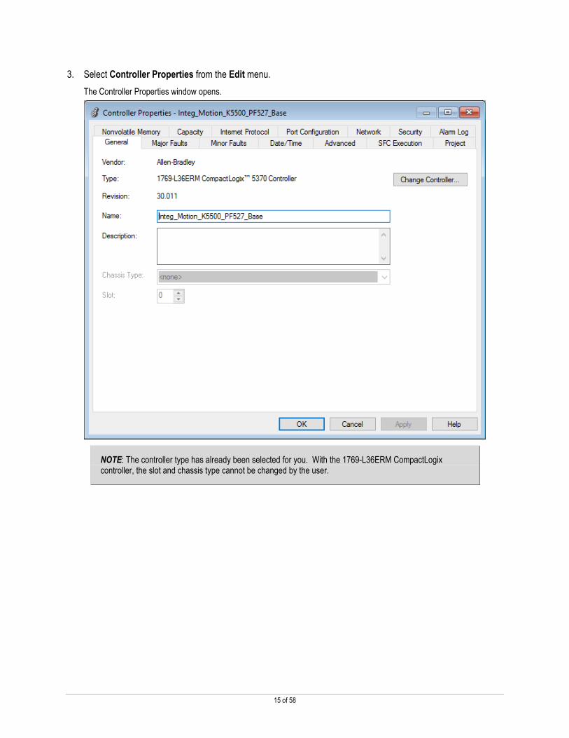
3. Select Controller Properties from the Edit menu.
The Controller Properties window opens.
NOTE: The controller type has already been selected for you. With the 1769-L36ERM CompactLogix controller, the slot and chassis type cannot be changed by the user.

16 of 58
4. Select the Date/Time tab and check the Enable Time Synchronization box to enable Integrated Motion on
EtherNet/IP in your project.
5. Click Apply, then OK to close the Controller Properties window.

17 of 58
Add Drive Hardware
Next you will add a Kinetix 5500 drive (Drive02) to the I/O configuration. Drive01 and Drive03 (Kinetix 5500 & PowerFlex 527)
have already been pre-configured for you.
1. Right-click on the Ethernet network icon and select New Module.
The Select Module Type window opens.
2. In the search box, type ‘5500’ and watch as the list repopulates. Select the catalog number 2198-H003-ERS
and click Create.

18 of 58
3. On the General tab in the New Module window.
� Type ‘Drive02’ in the Name field.
� Select Private Network, and set the Ethernet address to 192.168.1.25.
� Click OK.
TIP: The Kinetix 5500 IP address can be configured from the HIM of the drive OR you can use DHCP to assign an IP address. On the HIM navigate to Settings -> Network -> Static IP to change the static IP address or Settings -> Network -> DHCP to set up DHCP.
4. In the Select Module Type window, press Close.
The drive that you just added will now appear under the Ethernet network in your I/O configuration.

19 of 58
5. To complete the drive configuration, right-click on Drive02 and select Properties.
6. Navigate to the Power tab in the Module Properties window.
� Set Voltage to 200-240 VAC.
� Change AC Input Phasing to Single Phase.
� Set Bus Configuration to Standalone.
� Click Apply.
20 of 58
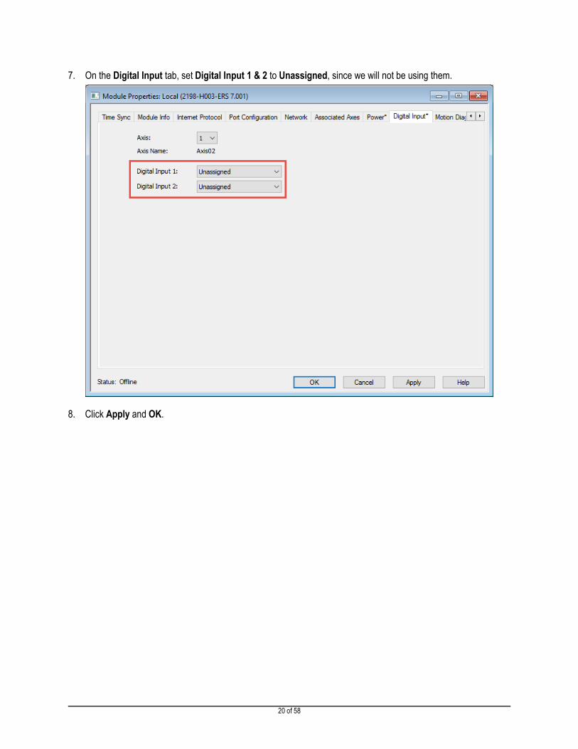
7. On the Digital Input tab, set Digital Input 1 & 2 to Unassigned, since we will not be using them.
8. Click Apply and OK.

21 of 58
Configure Axis Properties
In this section you will configure a new axis (Axis02) for the Kinetix 5500 and associated VPL motor. Axis01 and Axis03 have
already been configured for you.
1. Right click on the MotionGroup, and select New Axis -> AXIS_CIP_DRIVE
2. Name the axis Axis02, check the Open AXIS_CIP_DRIVE configuration check box and click Create.

22 of 58
3. From the General tab of Axis02 Properties, associate the Kinetix 5500 named Drive02 to Axis02.
4. Click Apply.
23 of 58
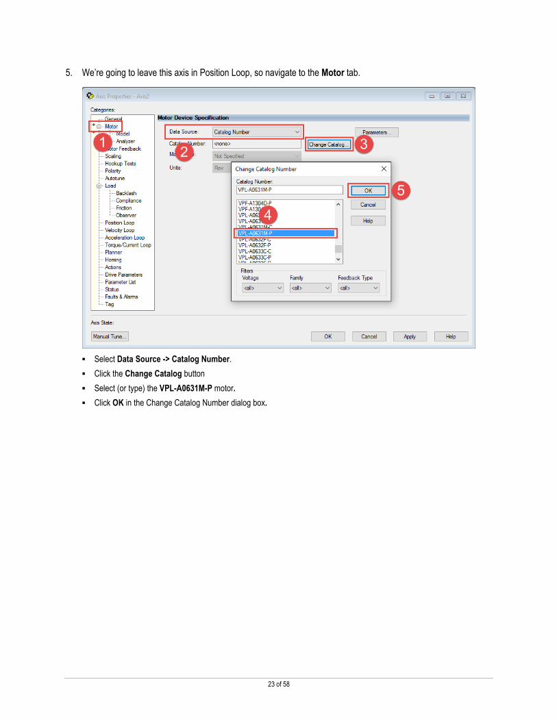
5. We’re going to leave this axis in Position Loop, so navigate to the Motor tab.
� Select Data Source -> Catalog Number.
� Click the Change Catalog button
� Select (or type) the VPL-A0631M-P motor.
� Click OK in the Change Catalog Number dialog box.

24 of 58
6. Click Apply to save changes.
7. From the Scaling tab, change the units to ‘revs’ and click Apply to save changes.

25 of 58
8. Click the Verify Controller button on the Logix Designer toolbar.
The system verifies your Logix controller program and displays error/warnings, if any, in the status window.
9. Select Save As… from the File menu and save your program using a name of your choosing.

26 of 58
Lab 2: Commission a Motion System (Estimated Time 15 Minutes)
In this lab we will guide you through the process of commissioning an Integrated Motion System. You will download your
controller project, execute a hookup test on an axis, configure an axis for tuningless operation, and control an axis with Motion
Direct Commands.
NOTE: This lab builds from Lab 1: Configure a Motion System. If you have not completed Lab 1, begin this lab by opening the Lab_2_Integ_Motion_Commission.acd file in the Lab Files folder on the desktop.
Download Your Motion Project
1. Select Who Active from the Communications menu.
The Who Active window will open.
2. Under the AB_ETHIP-1 driver, find the 1769-L36ERM processor at 192.168.1.12.
Verify the controller path is set to AB_ETHIP-1\192.168.1.12, otherwise, highlight the controller and click Set Project Path.
3. Verify that the operation mode switch on the controller is in the REM (remote) position. Ensure that the Kinetix
5500/PF527 demo is fully “powered-up”.
4. Click the Download button in the Who Active window.
The Download window will open.
5. Click the Download button to send the program to the controller.
27 of 58
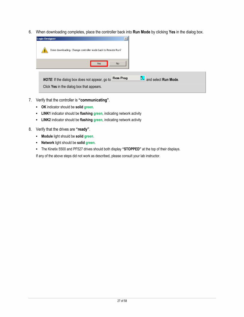
6. When downloading completes, place the controller back into Run Mode by clicking Yes in the dialog box.
NOTE: If the dialog box does not appear, go to and select Run Mode.
Click Yes in the dialog box that appears.
7. Verify that the controller is “communicating”.
� OK indicator should be solid green.
� LINK1 indicator should be flashing green, indicating network activity
� LINK2 indicator should be flashing green, indicating network activity
8. Verify that the drives are “ready”.
� Module light should be solid green.
� Network light should be solid green.
� The Kinetix 5500 and PF527 drives should both display “STOPPED” at the top of their displays.
If any of the above steps did not work as described, please consult your lab instructor.
28 of 58
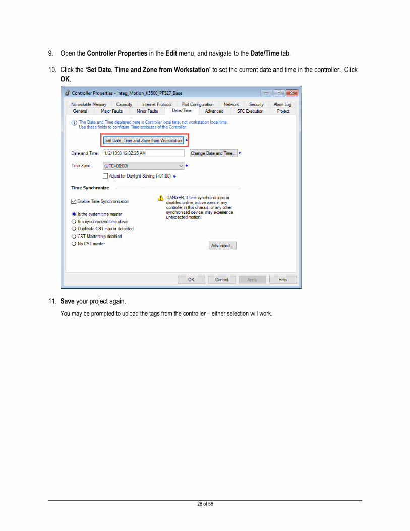
9. Open the Controller Properties in the Edit menu, and navigate to the Date/Time tab.
10. Click the ‘Set Date, Time and Zone from Workstation’ to set the current date and time in the controller. Click
OK.
11. Save your project again.
You may be prompted to upload the tags from the controller – either selection will work.

29 of 58
Execute Axis Hookup Tests
In this section of the lab, you will run the Motor and Feedback Hookup Test. The Motor and Feedback test applies motion to the
motor allowing the user to verify the power and feedback connections between the drive and motor. This test also establishes
the forward or positive direction of axis motion.
1. You should be Online with the controller.
2. In the Axis Properties window, navigate to the Hookup Tests page.
Verify the Test Distance is ‘1.0’ rev. This will provide enough axis travel to detect a marker. Test State should display
Ready.
The Motor and Feedback Hookup Test makes the axis move even when the controller is in program mode.
3. Press Start to conduct the test.
Once the Start button has been pressed, the axis will immediately begin to move.

30 of 58
4. The Motor and Feedback Test window opens.
You should observe Axis02 move approximately one revolution in the CW direction.
5. When the motor has completed one revolution and the drive has received the encoder signals correctly, the Test
State will change from Executing to Passed.
Click OK.
6. Click Yes if the axis moved in the forward or positive (CW) direction.

31 of 58
7. Click Accept Test Results to update/save the Motor and Feedback Polarity settings.

32 of 58
Configure Kinetix 5500 Drives for Tuningless Operation
Closed-loop servo systems require settings for the control loop gain and filter values to ensure that the load accurately follows
the desired input-command signal. The process of adjusting and refining the gain and filter configuration is called tuning.
With the tuning features of the Kinetix® 5000 servo drive family (Kinetix 5500 and Kinetix 5700 drives), tuningless operation can
now be achieved without compromising performance.
Load Observer
Let’s begin by configuring the Load Observer feature for Axis02.
1. If the Axis Properties window is not already open, right-click on Axis02 and select Properties.
The Axis Properties window opens.
2. Navigate to the Autotune page. Set the Application Type to ‘Custom’, and clear the ‘Torque Low Pass Filter’
checkbox.
.

33 of 58
3. Navigate to the Load tab and verify that the Load Ratio is zero; otherwise, set it to 0.

34 of 58
4. Under the Load category, select Observer. From the drop down select Load Observer with Velocity Estimate
and click Apply.
Once applied the Load Observer Bandwidth and other gains are set automatically.
The Load Observer feature operates in real time while the machine is running. During machine operation, the Load
Observer estimates the mechanical load inertia on the motor and compensates for it. The result is that the drive controls the
motor as if it is unloaded, which provides a relatively high level of drive performance. In addition, the drive automatically
compensates for mechanical variations in the system such as changing loads, compliance, and machine wear over time.

35 of 58
Tracking Notch
Now let’s configure the Tracking Notch feature for Axis02.
1. Under the Load category, select Compliance.
2. From the Adaptive Tuning Configuration pull-down menu, choose Tracking Notch and click Apply to save
the changes.
That’s it!! The Tracking Notch filter operates in real time while the machine runs. During machine operation, the drive
measures the mechanical resonances in the system and dynamically sets the notch filter frequency to mitigate the
resonances.
By using both the Load Observer and the Tracking Notch filter in Kinetix 5000 drives, most applications no longer require
tuning procedures and tests during the commissioning process to achieve an effective level of machine performance.
3. Click OK to close Axis02 properties.
4. Save your project.
You may be prompted to upload the tags from the controller – either selection will work.
36 of 58
Use Motion Direct Commands
Motion Direct Commands let you issue motion commands without having to write or execute an application program. You must
be online with the controller to execute a Motion Direct Command. Let’s see how these work using Axis02 of the project.
Jogging an Axis Using Motion Direct Commands
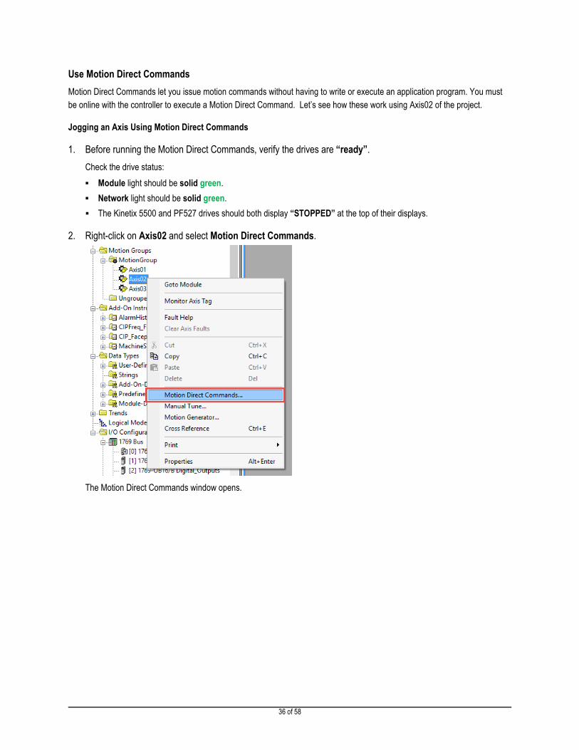
1. Before running the Motion Direct Commands, verify the drives are “ready”.
Check the drive status:
� Module light should be solid green.
� Network light should be solid green.
� The Kinetix 5500 and PF527 drives should both display “STOPPED” at the top of their displays.
2. Right-click on Axis02 and select Motion Direct Commands.
The Motion Direct Commands window opens.

37 of 58
3. Take a moment to look through all the commands available to you by moving the mouse cursor over the
instructions.
4. Select the Motion Servo On (MSO) instruction.
The MSO instruction enables the specified axis by activating both the drive amplifier and drive control loop.
5. Click Execute.
6. You should see an indication that the command was executed in the Errors window.
38 of 58
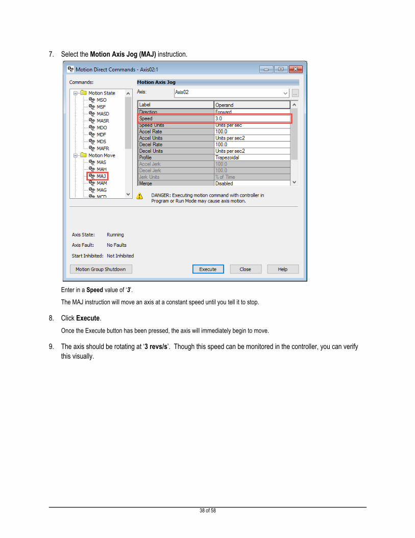
7. Select the Motion Axis Jog (MAJ) instruction.
Enter in a Speed value of ‘3’.
The MAJ instruction will move an axis at a constant speed until you tell it to stop.
8. Click Execute.
Once the Execute button has been pressed, the axis will immediately begin to move.
9. The axis should be rotating at ‘3 revs/s’. Though this speed can be monitored in the controller, you can verify
this visually.

39 of 58
Varying the Speed of the Axis Using a Motion Direct Command
1. Select the Motion Change Dynamics (MCD) instruction.
Set Change Speed to Yes and enter a Speed of ‘12’.
The MCD instruction will selectively change the speed, acceleration rate, or deceleration rate of a move and/or jog profile in
process.
2. Click Execute.
You should see a clear increase in the rotational speed of the axis.
Remember, we initially had configured the axis to jog at 3 revs/s. Now it’s rotating at four times that speed and without
having to write an application program – everything was done “on the fly” using Motion Direct Commands!

40 of 58
Stop the Axis Using a Motion Direct Command
1. Select the Motion Axis Stop (MAS) instruction.
The MAS instruction will initiate a controlled stop of any motion process on the designated axis.
2. Click Execute.
3. When the axis has slowed to a stop, select and execute the Motion Servo Off (MSF) instruction.
The MSF instruction disables the specified axis by deactivating both the drive amplifier and the drive control loop.
4. Click Execute and the Kinetix 5500 should now show a STOPPED status on the HIM.
5. If you have additional time, use what you’ve learned about Motion Direct Commands with Axis03.

41 of 58
Lab 3: Program a Motion System (Estimated Time 20 Minutes)
In this lab you will learn motion programming concepts by building a motion program, using basic motion instructions, and
navigating the Logix Designer interface.
NOTE: This lab builds from Lab 2: Commission a Motion System. If you have not completed Lab 2, begin this lab by opening the Lab_3_Integ_Motion_Program file in the Lab Files folder on the desktop and downloading it to the controller.
To download:
- Select Download in the Communications menu.
- Click Download in the dialog box that appears.
When downloading completes, place the controller back into REM RUN mode.
Explore an Existing Sequencer Program
In this section you will explore a simple routine to understand how a RUN and a STOP SEQUENCE can be used in a motion
application.
1. Under the MainTask in the Controller Organizer, expand the P01_Application folder, and double click on the
R10_ApplicationCode routine to open the Ladder Editor.

42 of 58
2. Take a moment to examine the application logic.
You’ll notice there are two sections of code: the RUN SEQUENCE and the STOP SEQUENCE.
The run sequence follows a programming structure called a sequencer and currently consists of a single step. When the
controller receives a start command, from the HMI for example, the RunSEQ[0] tag will be set to a 1, and the run sequence
will execute.
Similarly, when the controller receives a stop command, the StopSEQ[0] tag will be set to a 1, and the stop sequence will
execute.
Let’s observe how these sequences work.
3. Minimize Logix Designer so that the HMI screen on the desktop can be seen.
4. If the machine is currently in the ABORTED state…
… press Clear Faults.
After a few moments the machine should transition to the STOPPED state.

43 of 58
5. Press Start, and then return to the Logix Designer window.
The axes enable and begin operating according to the RUN SEQUENCE logic. The RUN SEQUENCE currently consists of
a single step in which Axis01 moves 10 revolutions at a speed of 2 revs/sec. When the move completes, the Motion Axis
Move instruction transitions to the Process Complete (PC) status and the MOV instruction sets the RunSEQ[0] tag to 999 to
indicate that the sequencer has completed.
Now let’s examine the STOP SEQUENCE.
6. Minimize Logix Designer so that the HMI screen on the desktop can be seen.

44 of 58
7. Press Stop, and then return to the Logix Designer window.
The STOP SEQUENCE consists of three steps:
� First, all three axes are stopped with Motion Axis Stop instructions. If an error occurs during any of the moves, the
Inst_Error bit is set. When all three axes reach a Stopped state, the StopSEQ[0] tag is set to a value of 10 and the
sequence moves to the next step.
� Next, a disable command is sent to each of the servo drives. When the status of the drives indicate that they are
disabled, the StopSEQ[0] tag is set to a value of 20 and the sequence moves to the final step.
� The last step provides an indication that the STOP SEQUENCE is complete by setting the StopSEQ[0] tag to 999.
45 of 58
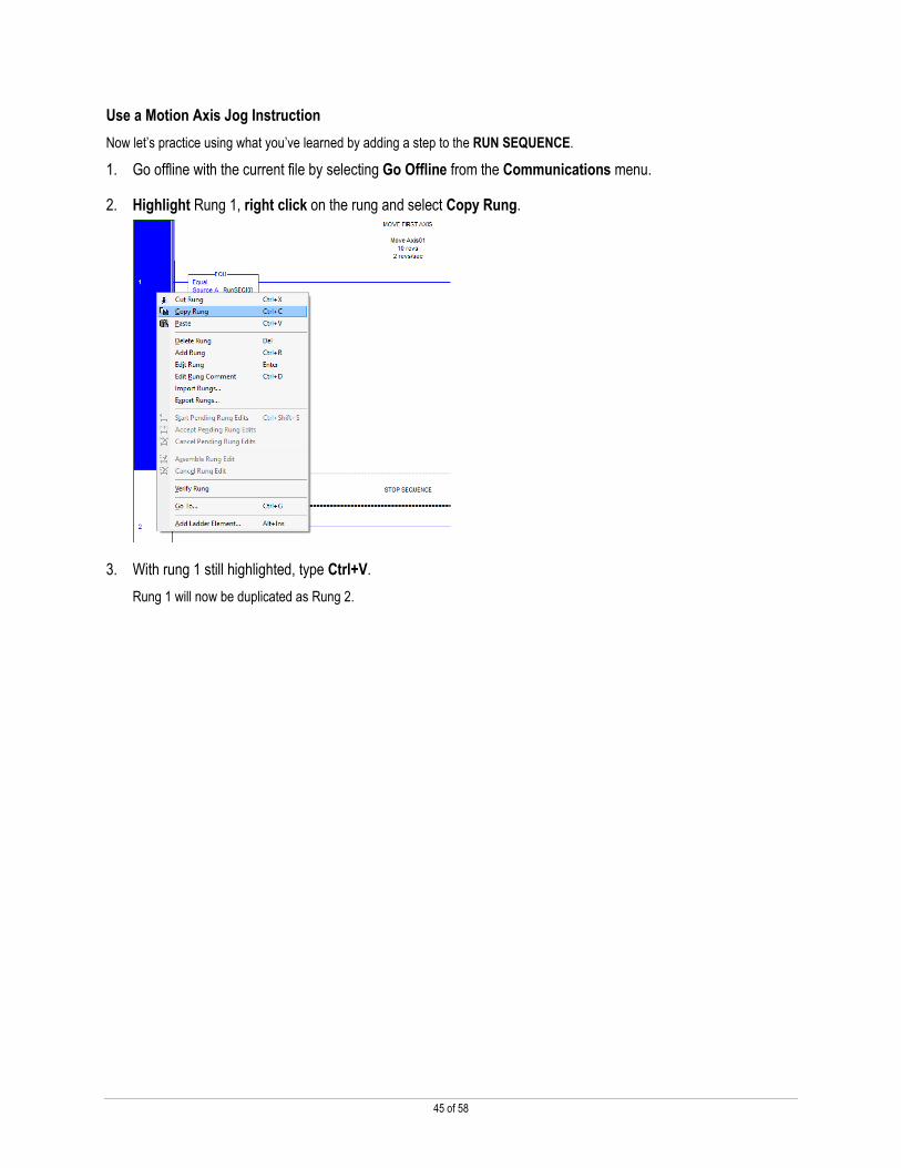
Use a Motion Axis Jog Instruction
Now let’s practice using what you’ve learned by adding a step to the RUN SEQUENCE.
1. Go offline with the current file by selecting Go Offline from the Communications menu.
2. Highlight Rung 1, right click on the rung and select Copy Rung.
3. With rung 1 still highlighted, type Ctrl+V.
Rung 1 will now be duplicated as Rung 2.

46 of 58
4. Let’s modify the instructions to add the second step in the sequencer. Rather than setting the RunSEQ[0] tag to
a value of 999 when the MAM instruction completes, we want to move to the new step, so…
� In rung 1: Change the Source in the MOV instruction from 999 to 10.
� In rung 2: Change the Source B in the EQU instruction from 1 to 10.
NOTE: The MOV instruction in rung 2 now sets the StopSEQ[0] tag to 999 to indicate that the STOP SEQUENCE is complete.
5. In Rung 2, highlight the MAM instruction and delete it.
6. In the Language Element toolbar, navigate to the right by clicking the right arrow, and select the Motion Move
Element Group.

47 of 58
7. Click and drag the MAJ instruction to where the MAM instruction was that you deleted from rung 2.
A green circle will appear at the location where the instruction will be added.
8. Enter the following information into the Motion Axis Jog instruction that you just added to the rung to program
Axis02 to execute a jog:
NOTE: When you hover over various Instruction entry fields, a description of the options and operand types for that entry will appear in the bottom left corner of the Logix Designer window. For example, here is information for the Direction entry in the MAJ instruction:
If you’d like more information on the MAJ instruction, highlight it, and press F1 to open the Help file.

48 of 58
9. We want to indicate the RUN SEQUENCE is complete once the MAJ instruction is in process. While holding
down the Ctrl key, drag and drop the Motion Control tag for the MAJ instruction to the XIC instruction in the
branch. You will see a green circle appear next to the XIC instruction.
10. Now double click the tag you just copied into the XIC instruction, and add .IP to the end of the tag name. The
XIC instruction in rung 2 should look like this when you are finished:

49 of 58
11. Now double click on the comments for rung 2, and modify the text to say that we are jogging Axis02. Your
completed rung 2 should look similar to this:
12. Select Download in the Communications menu.
13. Click Download in the dialog box that appears.
14. When downloading completes, put the controller back into Run Mode by clicking Yes in the dialog box.
NOTE: If the dialog box does not appear, go to and select Run Mode.
Click Yes in the dialog box that appears.

50 of 58
15. Minimize Logix Designer so that the HMI screen on the desktop can be seen.
16. If the machine is currently in the ABORTED state…
… press Clear Faults.
After a few moments the machine should transition to the STOPPED state.
17. Press Start, and watch the motors spin in the demo box according to your sequencer logic.
Axis01 should execute a move to 10 revolutions and then Axis02 should begin jogging at a speed of 3 revs/sec. Please
consult your instructor if you have any questions.
18. Press Stop after Axis02 begins jogging.

51 of 58
Add a Motion Change Dynamics Instruction
In this section, you will utilize a Motion Change Dynamics instruction to change the jog speed of Axis02 after three seconds.
Let’s begin by importing a rung of code that was pre-programmed for you.
1. Go offline with the current file by selecting Go Offline from the Communications menu.
2. Highlight Rung 2, right click, and select Import Rungs.

52 of 58
3. Open the Rung_3_Import.L5X file in the Lab Files folder on the desktop.
The Import Configuration window allows you to configure how the rung is imported and how the imported tags are managed.
4. You do not need to modify the Import Configuration, so click OK in the Import Configuration window.
The sequence logic to execute a 3 second dwell will appear in rung 3.

53 of 58
5. Rather than setting the RunSEQ[0] tag to a value of 999 once the jog is In Process, we want to move to the new
step, so…
� In rung 2: Change the Source in the MOV instruction from 999 to 20.
54 of 58
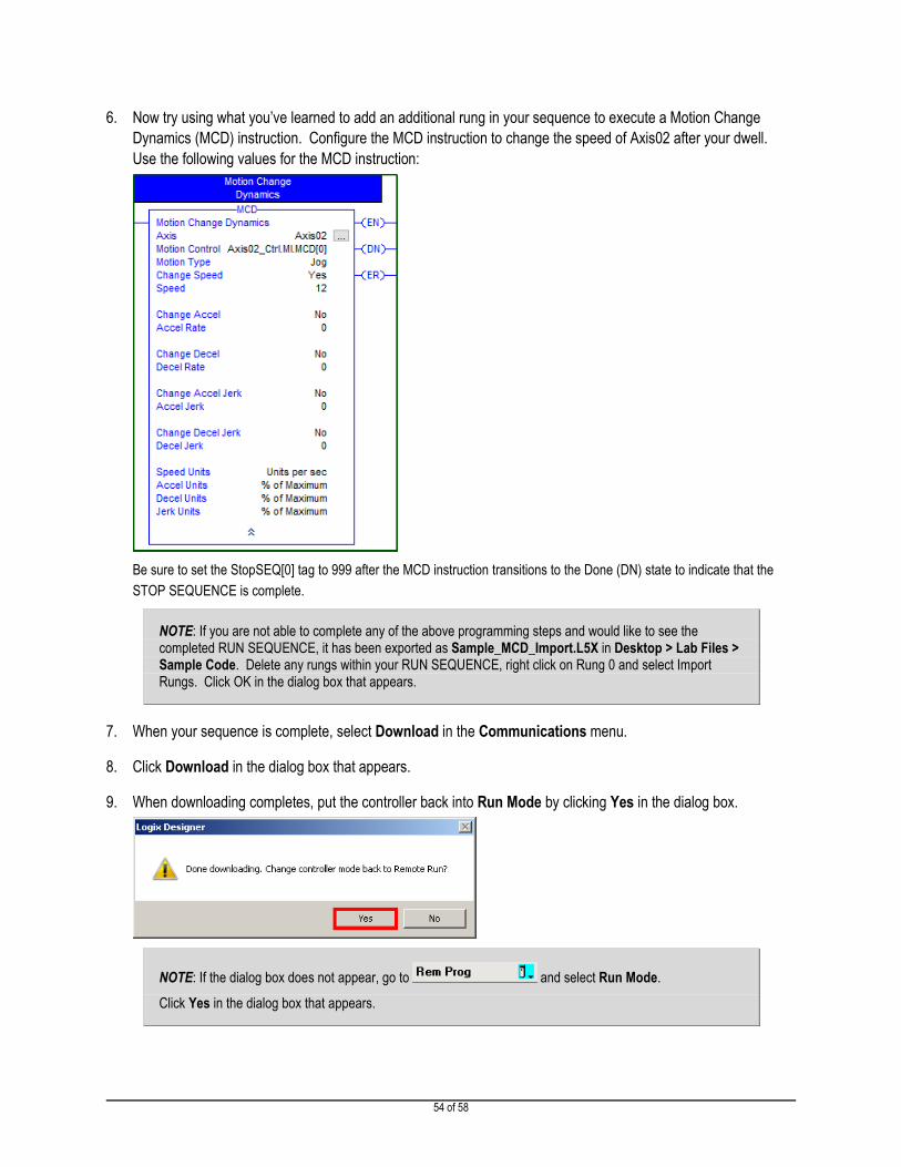
6. Now try using what you’ve learned to add an additional rung in your sequence to execute a Motion Change
Dynamics (MCD) instruction. Configure the MCD instruction to change the speed of Axis02 after your dwell.
Use the following values for the MCD instruction:
Be sure to set the StopSEQ[0] tag to 999 after the MCD instruction transitions to the Done (DN) state to indicate that the
STOP SEQUENCE is complete.
NOTE: If you are not able to complete any of the above programming steps and would like to see the completed RUN SEQUENCE, it has been exported as Sample_MCD_Import.L5X in Desktop > Lab Files > Sample Code. Delete any rungs within your RUN SEQUENCE, right click on Rung 0 and select Import Rungs. Click OK in the dialog box that appears.
7. When your sequence is complete, select Download in the Communications menu.
8. Click Download in the dialog box that appears.
9. When downloading completes, put the controller back into Run Mode by clicking Yes in the dialog box.
NOTE: If the dialog box does not appear, go to and select Run Mode.
Click Yes in the dialog box that appears.
55 of 58
10. Minimize Logix Designer so that the HMI screen on the desktop can be seen.
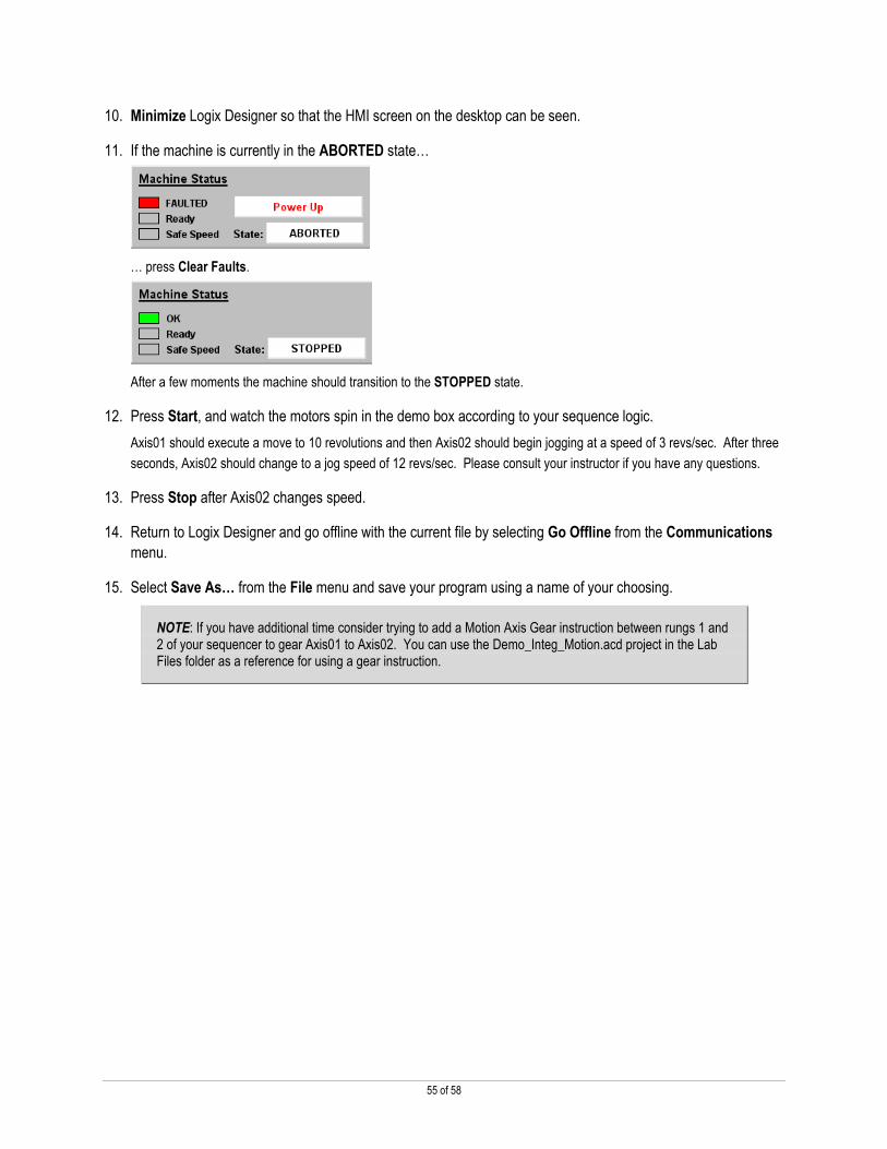
11. If the machine is currently in the ABORTED state…
… press Clear Faults.
After a few moments the machine should transition to the STOPPED state.
12. Press Start, and watch the motors spin in the demo box according to your sequence logic.
Axis01 should execute a move to 10 revolutions and then Axis02 should begin jogging at a speed of 3 revs/sec. After three
seconds, Axis02 should change to a jog speed of 12 revs/sec. Please consult your instructor if you have any questions.
13. Press Stop after Axis02 changes speed.
14. Return to Logix Designer and go offline with the current file by selecting Go Offline from the Communications
menu.
15. Select Save As… from the File menu and save your program using a name of your choosing.
NOTE: If you have additional time consider trying to add a Motion Axis Gear instruction between rungs 1 and 2 of your sequencer to gear Axis01 to Axis02. You can use the Demo_Integ_Motion.acd project in the Lab Files folder as a reference for using a gear instruction.

56 of 58
Lab 4: Troubleshoot a Motion System (Estimated Time 15 Minutes)
This lab is designed to allow you to experience the troubleshooting process by exploring a file with four errors. The goal is to
eliminate all of the errors so that you can spin the motors in the demo box.
NOTE: The errors in this lab are resolved exclusively in the Logix Designer software. You will not be required to make any physical modifications to the hardware in the demo boxes. In addition, you should not make any changes to the settings through the drive HIM’s.
Download the Troubleshooting Project
1. In Logix Designer, click Open in the File menu.
The Open window appears. You do not need to save changes to your existing file.
2. Browse to the folder Lab Files on the desktop and open the Lab_4_Integ_Motion_Troubleshoot.ACD file.
3. Select Download in the Communications menu.
4. Click Download in the dialog box that appears.
5. When downloading completes, put the controller back into Run Mode by clicking Yes in the dialog box.
NOTE: If the dialog box does not appear, go to and select Run Mode.
Click Yes in the dialog box that appears.
6. You are now ready to begin troubleshooting the system.
WARNING: Be aware that at some point in the troubleshooting process a motor in the demo box will make a loud noise
after pressing Start. Do not be alarmed when this occurs. Simply press Stop.
NOTE: This lab is meant to allow you to identify the appropriate clues to locate the various errors with the project. We encourage you to try to troubleshoot the project without step-by-step instructions, however we have included the solutions in the Troubleshooting Solutions folder in the Lab Files folder on the desktop if you would like to see the solutions.

57 of 58
Notes

58 of 58
Publication CE-DM001-EN-P — April 2017 Copyright© 2016 Rockwell Automation, Inc. All rights reserved.
Supersedes Publication CE-DM001-EN-P — Sept 2016