l GEOPHYSICAL REPORT l ON THE l NINETEEN CLAIM BLOCK
45
l l l l l l l l l l l l l l l l l l l 32D12SW8139 3.11299 GARRISON 010 GEOPHYSICAL REPORT ON THE NINETEEN CLAIM BLOCK FOR FINDORE MINERALS INC. RECEIVED JUN i 3 1988 MINING LANDS SECTION R.J. Meikle Exsics Exploration Ltd April 19, 1988 t--
Transcript of l GEOPHYSICAL REPORT l ON THE l NINETEEN CLAIM BLOCK

l l l l l l l l l l l l l l l l l l l
32D12SW8139 3.11299 GARRISON 010
GEOPHYSICAL REPORT
ON THE
NINETEEN CLAIM BLOCK
FOR
FINDORE MINERALS INC.
RECEIVED
JUN i 3 1988
MINING LANDS SECTION
R.J. MeikleExsics Exploration LtdApril 19, 1988
t--

l l l l l l l l l l l l l l l l l l l
32D13SWei39 3.11399 GARRISON
TABLE OF CONTENTS
O1OC
INTRODUCTION. . , .
LOCATION AND ACCESS
PERSONNEL , . . . .
CLAIM STATUS. . . .
Page l
1
2
2
GEOLOGY,
SURVEY SPECIFICATIONSMagnetometer Survey . . . . . . . . . . . . . , . 3Horizontal Loop-EM Survey . . . . . . . , . . . . k
INDUCED POLARIZATION SURVEY
POLE-DIPOLE ARRAY . . . . .
RESULTS . . . . . . . . . .
RECOMMENDATIONS . . . . . .
k
5
6
9
Map in Map tt2 Map #3 Map #fc
LIST OF MAPS
Contoured Magnetometer SurveyMax Min I I 1777 HzMax Min I I kkk HzFraser Filtered Chargeability
LIST OF FIGURES
Figure l General Location MapFigure 2 Property Location MapFigure 3 Claim Map
APPENDICES
Appendix A Fraser Filter MethodAppendix B Apex Max Min II EMAppendix C EDA Omni IV MagnetometerAppendix D EDA IP-2 ReceiverAppendix E Induced Polarization Transmitters TSQ Series

l l
INTRODUCTION
f A program of Linecutting, Magnetometer Survey, Horizontal
^ Loop-EM Survey and Induced Polarization Survey was carried out on
* a group of 19 unpatented mining claims in Garrison Twp., Larder
l Lake Mining Division, for Pindore Minerals Inc. The work was
carried out on a contract basis by Exsics Exploration Ltd.,
l Timmins, Ontario.
The property actually consists of 21 claims, two of which
" have been dealt with in a recent report by R. Meikle, April 7,
H 1988. This report deals with the results of the surveys on the
whole property.
lLOCATION AND ACCESS
l The property is located approximately 6 km east of Perry
m Lake in Garrison Twp., on Hwy 101, east of the town of Matheson.
The property is bounded on the west by the Michaud-Garrison Twp
l line and on the south by Hwy 101.
Access is excellent year-round via Hwy 101 east.
l
l
l
l
l
l

ltl:?X !LWI ^f-WV't:'*
~* ' ~"
l
l
l
EXSICS EXPLORATION LTD,f JO. Bm HW, PIN-7X1SutU O, HolUnfW Wdg, TtanlM Oot.TiliphtfM! TOS-2IT-41S1
CLIENT: FINDORE MINERALS INC.
PROPERTY: GARRISON 21 CLAIM
TITLE:GENERAL LOCATION MAP Fig l
Date: April 1988
Drawn: L.R.Scale:Interp:
NTS:Job No. EE-84

N.T.S.
ale: 1:50,000.
,- v J N - -* f ' .,7 ; V 1 'Im ) MA K'A T H
?, • Doklip' ,, Hospital PI 1'
\hi,ihl

l l l l l l l l l l l l l l l l l l l
PERSONNEL
The following personnel were directly involved with the
project between Nov 10, 1987-3an, 2k, 1988:
Wayne Pearson . . . , . . . . . . Timmins, Ontario
Dan Collin . . . . . . . . . . . .
Ken Eggleston . . . . . . . . . . " "
Brian Keen . . . . . . . . . . .
Mike Mickey , . . . . . . . . . North Bay, Ontario
Steve Schwartz . . . . . , . . . Timmins, Ontario
Dave Clement . . . . . . . , . .
CLAIM STATUS
The property consists of 19 contiguous, unpatented mining
claims in the west-central portion of Garrison Township in the
Larder Lake Mining Division (fig.2).
The claims are held in the name of Pindore Minerals Inc.,
567 Pine Street North, Timmins, Ontario. The claim numbers are
as follows:
997939-997951 incl = 13 claims Garrison Twp
1025879-102588^ incl - 6 claims Garrison Twp
- 2 -

EXSICS EXPLORATION LTD,P.O. Box UIO. P4N-7XI
13, Hotllngir Bldg, Tim** Ont. 7P5-2f|.(61
CLIENT: FINDORF- MINERALS INC.
PROPERTY: GARRISON 21 CLAIM
CLAIM MAPDate: April 1988

l l
GEOLOGY
l Map Reference:
1. Map 19&9-1: Township of Garrison, District of Cochrane,
l Ontario, Scaie 1:12,000 O. D. M. 19b9
The immediate area is believed to be underlain by
l intermediate to mafic volcanics, Diorite and Gabbro intrusives
are indicated in outcrop along the south boundary. Ultra mafics
8 are present in the northern part of the claim group. The
property geology will be dealt with in subsequent follow-up
reports .
l
lSURVEY SPECIFICATIONS
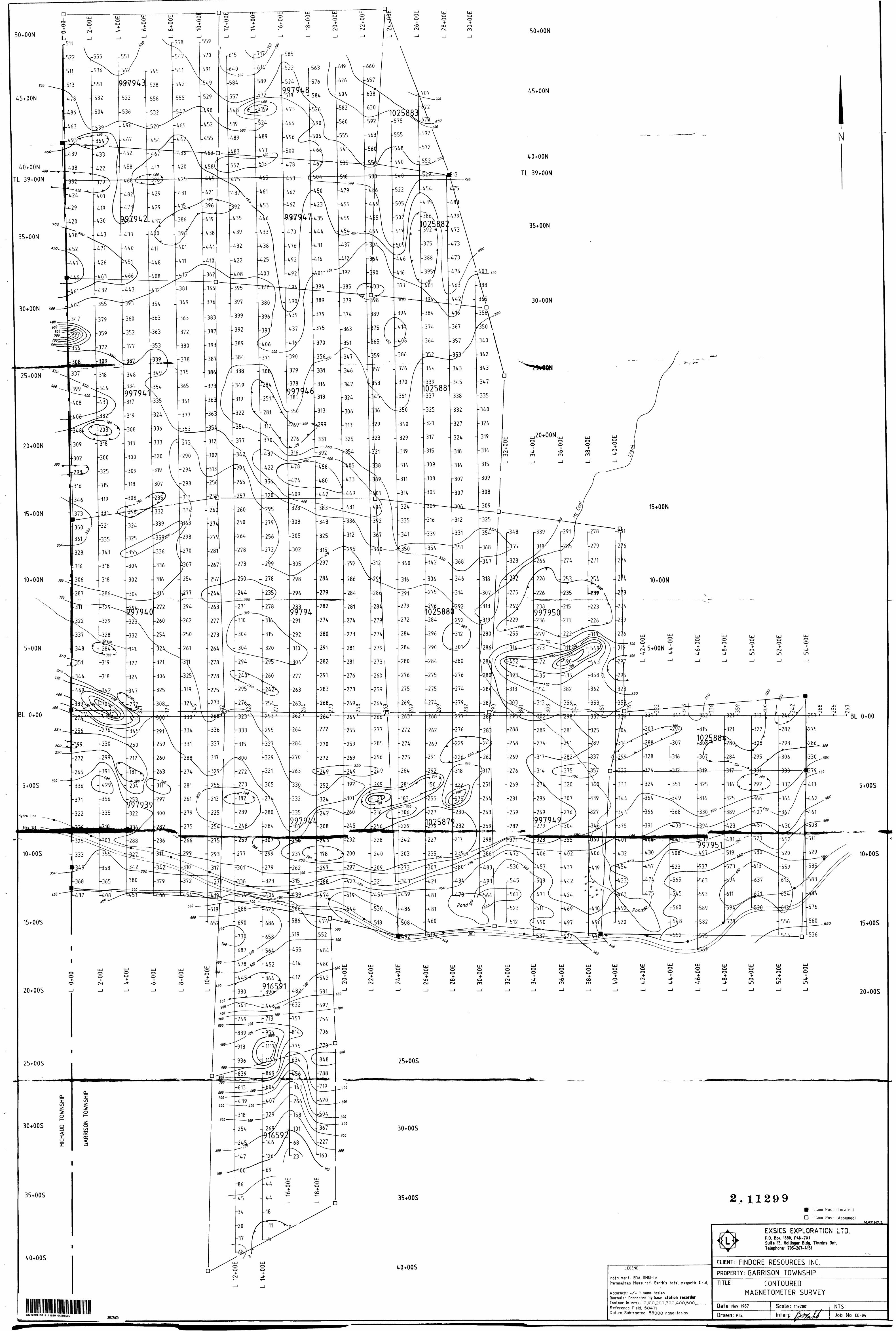
l Magnetometer Survey: A total of kk km was surveyed using the
n following parameters:
Instrument: EDA Omni IV Proton Precession
l Accuracy : +X- one nano tesla
Diurnals corrected by compatable Omni IV base station
l recorder using a 30 second sample interval
. Reading Interval: 100 feet
' Data Presentation: Plan Contoured Map No. l Scale l'^200ft
l
l
l
l
l

lHorizontal Loop Survey: A total of kk km was surveyed using the
l following parameters:
Instrument: Apex Max Min li
l Mode : Maximum Coupled, Co-Planner
m Coil Spacing: 500 ft
Reading Interval: 100 ft
l Frequency: 1777 Hz, kkk Hz
Data Presentation: Plan profiled Map No. 2-1777 Hz
l Scale l" = 200 ft
l
l
l
Map No. 3- kkk Hz Scale I" - 200 ft
l INDUCED POLARIZATION SURVEY
The IP method involves applying voltage across two
l electrodes in a pulsed manner i.e. 2 second on, 2 second off. A
j* second "dipole" or electrode pair, measures the residual
potential or voltage between them after the voltage is shut off
l or during the 2 second off cycle. The potential is recorded at
different times after the shut off. If, for example, there is
P sulphide mineralization within the measuring dipoles, they will
. be polarized or charges set up in the sulphide particles. This
polarization gives the zone a capacitor effect, thereby blocking
l the current delay giving a higher chargeability reading.
A typical signature for many gold showings would be a
l chargeability high, resistivity high and magnetic low. This
would be characteristic of a mineralized, highly altered
carbonitized and/or silicified zone. However, this is by no
- It -

lmeans the only geological setting for gold, therefore every IP
l profile should be looked at individually and correlated with all
other geophysical-geological data.
m POLE-DIPOLE ARRAY
In this array, one electrode is fixed at an infinite point
l from the grid and one pole or current electrode plus a dipole or
two potential electrodes are moved in unison about the grid. In
l this case, the "a" spacing or distance between the two receiving
im potential electrodes was fixed at 100 feet while the distance
between the moving current electrodes and the nearest potential
l electrode was 100 feet, 200 feet and 300 feet, corresponding to
NM, 2 and 3 on the psuedosect ions.
l
Every second line (400 feet) was read using the following
parameters:
Method- - Time Domain
l Electrode Array - Pole Dipole
"a" spacing - 100 feet
l Pulse Duration - 2 seconds on, 2 seconds off
Delay Time - 650 ms
B Integration Time - 520 ms
l
l
l
l
l
- 5 -

l l
Receiver - EDA IP-2
l Transmitter - IPC-7 2.5 kVA
Data Presentation- Map No. k- Plan contoured map of
B Fraser Filtered Chargeabi l i ti es
Scale l" - 200 feet
Individual Psuedo-sections with:
l -fraser filtered chargebility
-chargeabi lities in section and
l profiled
-apparent resistivities
l
m
l RESULTS
Magnetometer Survey; The maximum magnetic relief over the
l property is approximately 800 nT, distributed as follows:
M 1. From approximately 30 N to the north end there is a
higher magnetic susceptabi li ty which is probably related to a
l band of ultramafics.
2. The area between 30 N and approximately 10 S is
l relatively uniform and lower than ultramafics. This area is
M interpreted as mafic volcanics.
" 3. This is a feature which runs diagonally from L 0/30 N to
l L 40 B/0 -* 00. It has a higher susceptabi l i ty than the above
mentioned #2. This could be related to a NW trending fault zone
l which is documented to the NW of the property.
l l l
- 6 -

lk. This is a series of EW trending isolated magnetic low
l running across the property just north of the highway. They
l
l
l
l
l
l
l
l
couid be caused by carbonate alteration.
5. This is an area of higher magnetic susceptability
between 10 S and 30 S. It is coincident with a band of known
ultramaf ics.
6. There appears to be a distinct contact at approximately
30 S where the magnetic susceptabil ity drops about 600
nano-teslas to the south. This is thought to be a contact
between the ultramafics, and sediments to the south.
Horizontal Loop-EM Survey: The horizontal loop survey outlined
l several weak conductors. They are described in order of
conductivity as follows:
g A- This conductor has the strongest amplitudes on the
property. It extends from L O to L k E inclusive, centered at
approximately 600 S. It calculates to approximately 2 mhos and a
B depth of 22 meters. It has a coincident, weak IP chargeability
high .
l C- This is a weak, 2 mhos conductor centered at 500 S on
L 38 E, kO E, k2 E, with the strongest response on L 40 E. It
B calculates to be approximately 57 meters deep.
l
- 7 -

l l
B- This anomaJy extends from L 16 E to L 30 E, varying in
l position but averaging at 500 S. The best in-phase response is
on L 16 E at 5 S. This response has a high positive shoulder on
B the south flank. The possibility exists that this positive
B quadrature is indicative of a buried bedrock ridge with the
anomaly at the edge of the ridge. The same is characteristic of
l the eastward extension of the anomaly. It can be argued that the
response on L 16 E is not part of the rest of the anomaly.
l D- This anomaly runs from L 30 E - L 36 E at approximately
m 100 N. It is a very weak conductor.
E- This anomaly runs from L 8 E - L 12 E at 2200 N. Again,
l it is on the north flank of a large positive quadrature shoulder.
It could possibly be an edge effect from a bedrock ridge.
Induced Polarization Survey; The IP survey outlined several
chargeable zones. EM anomalies A, C, have coincident
chargeability highs.
A high chargeability response on L 20 E/550 S and L 22 E/7 S
is coincident with a very weak EM anomaly not described above.
The only other IP feature is a very high chargeability
response on L 38 E from 0+50 S-300 N. The psuedosection
indicates a region of unchanging resistivities. The high
chargeabil i ties occur over two dipole set-ups. The chargeability
decay curve does not look good on the raw data. There is no
indication of this anomaly on either adjacent line. Thus, this
line is suspect and should be re-read.
l
l
l
l
l
l
l
l
l
l
- 8 -

l ll
l
l
M
l
l
l
l
l
Overall, the IP survey encountered some major technical
difficulties. The survey was conducted In late fall when the
ground was frozen. A large portion of the southern-central part
is underlain by esker material, which is extremely dry, making
sufficient ground contacts very difficult. This results in aB
large percentage of negative and/or no readings. A gradient
array was tried over this part of the grid but, high contact
resistance still impeded a proper survey. If additional IP
coverage is deemed warranted, a gradient array in late spring
time is recommended.
RECOMMENDATIONS
The following recommendations are based on the current
geophysical program. They should be re-evaluated after a
thorough compilation of the property and surrounding area inm
terms of previous work done and the most recent interpretation of
the geology. The area is an active one and most of the anomalies
detected are in close proximity to the assumed Pipestone Fault
Zone. As well, the T Jk H Resources zone appears to be striking
in the direction of the southern part of the property.B
l . EM anomalies A and C should be tested by diamond
l drilling, allowing for more overburden on anomaly C.
2. The IP anomaly on L 20 E/550 S should be tested by
J diamond drilling.
- 9 -

l l
3. If preliminary diamond drilling indicates economic
l and/or favourable geological structures, a Gradient Array IP
Survey should be conducted over the entire property in the late
l spring when there is maximum moisture content in the soil.
l
l
l
l
l
l
l
l
l
l
l
l
l
Respectfully submitted,
R. J. Meikle
- 10 -

1ll JlJ1
CERTIFICATION
I, Raymond Meikle of Timmins, Ontario hereby certify that:
1. I hold a three year Technologist Diploma from the Haileybury School of Mines, Haileybury, Ontario obtained in 1975.
2. I have been practising my profession since 1973 in Ontario, Quebec, NWT, Manitoba, New Brunswick, Nova Scotia for Teck Exploration Ltd., MetalIgeslIschaft Canada Ltd., Rayan Exploration., Sabina Industries Ltd., and most recently Exsics Exploration Ltd.
3. I have based conclusions and recommendationscontained in this report on knowledge of the area, my previous experience, and on the results of the field work conducted on the property during Nov, 1987-Feb, 1988 which was carried out under my overall supervision.
CO
Dated this.J9th day of-Apr., 1988 at Timmins, Ontario
R.J. Meikle

l l l l l l l l l l l l l l l l l l l
CERTIFICATION
I, Raymond Meikle of Timmins, Ontario hereby certify that:
1. I hold a three year Technologist Diploma from the Haileybury School of Mines, Haileybury, Ontario obtained in 1975.
2. l have been practising my profession since 1973 in Ontario, Quebec, NWT, Manitoba, New Brunswick, Nova Scotia for Teck Exploration Ltd., MetalIgeslIschaft Canada Ltd., Rayan Exploration., Sabina Industries Ltd., and most recently Exsics Exploration Ltd.
3. I have based conclusions and recommendationscontained in this report on knowledge of the area, my previous experience, and on the results of the field work conducted on the property during Nov, 1987-Feb, 1988 which was carried out under my overall supervision.
k. I hold no interest, directly or indirectly in this property other than professional fees, nor do I expect to receive any interest in the property or in Findore Minerals Inc. or any of it*s subsidiary companies.
Dated this-19th day o^Apr., 1988 at Timmins, Ontario
R. 3. Meikle

APPENDICES

APPENDIX A

l
ll l l l l l l l l l l l l lll
FRASER FILTER METHOD A ( \' ' '-. f , , , } ' ^ ,. * ( i ,,. , . .
-'^: W^:^^
'
FRASER FILTER METHOD B
DOU8U WEIftHUO P H
Filttrtd V Plot
-V-.-i.V.' 1 .. ''.' ;,,|!
- * . '•'•..' i '.-.' -, * V'-'-'i '^^'•':'^^\
METAL FACTOR CAUULAT10M
MF * CHAROEABILITY X 2000 M X ftCWTIVJTY
'-.' '. .,..l i .' -. .' .' . l ... ,. . '. -, ; - ' . :',-J . 'i-'..,..
; : :i
•:-;-\

APPENDIX B

i i\r 11EMl
pl lll
B Five frequencies: BBS, 444, BBS, 1777 and 3BBB Hz.B Maximum coupled C horizontal-loop ) .operation with
reference cable. . . ,' -:-{.!, ^ff|'/l*t,j'. i.". . ' ..m Minimum coupled operation with reference cable. m Vertical-loop operation without reference oable.m Coll separations: SB, BO, 1OO|1BO, BOO and BBOm
Cwith cable I or 100,800,300,400, BOO and BOO ft.m Reliable data from depths of up to ISO m C BOO ft).m Built-in voice communication circuitry with cable.m Tilt meters to control ooll orientation.

J JLJ J
J J
'J
J, J J j J
l l l l l l l l l l l l
SPECIFICATIONS :
Frequencies! 232,444,888,1777 and 3555Hz. Repeatability)
Modes of Operation: MAX: Transmitter coil plane end re ceiver coil plane horizontal (Max-ooupled; Horizontal-loop mode). Used with ref en cable.
M l N; Transmitter coil plane horizon tal and receiver coil plane ver tical (Min-coupled mode). Deed with reference cable.
V.L. ! Transmitter coil plane verti cal and receiver coil plane hori zontal (Vertlcel-loop mode). Used without reference cable, In parallel linea.
S5.50.100.150.800 S250m (MMO) or 1OO. BOO. 3OO. 4OO,BOOend BOO ft. (MMIIF). Coil separations In VL.mode not ra* etricted to fixed values. '
Parameters Read) - In-Phase end Quadrature compo nents of the secondary field l n MAX end MIN modes.
- Tilt-angle of the totel field In VL. mode .
*D.251tto±1*A normally, depending on conditions, frequencies end coil separation used.
Transmitter Output! - SSSHz : SSO AtmB . 444Hz iEOOAtm8- BBSHz s 12OAtms- 1777 Hz J 6OAtme-3555 Hz s 3OAtme
Receiver Batteries! 8V trans, radio type batteries (4). Life; approx, 35hrs. continuous du ty (alkaline, O.5 Ah), less in cold
'... : - , weather.
Coll Separations!
Readouts!
Boale Ranges!
Readability!
- Autometlo, direct reedout on SO mm (3.5") edgewise meters in MAX and MIN mode a. No null* ing or compensation necessary.
- Tilt angle end null In BO mm edge* wise meters In V.L.mode.
In-Phase: i2OV.,*1OO^ by push button switch .
Quadrature: *2OM. HOOT, by push button switch.
Tilt: i 75 "A slope.Null (VLJi Sensitivity adjustable
by separation switch.
In-Phase end Quadrature i Q.25 V. to O.5V. ; Tilti 1V. ,,
Transmitter Batteries t
Ref arena* Cable i
Voloa Link l
Indicator Lights i
12V 8 Ah Gel-type rechargeable battery. [Charger supplied).
Light weight S-conductor teflon csble for minimum friction. Unshield ed. All reference cables optional at extre coat. Please specify.
Built-in intercom system for voice communicetlon between re ceiver end transmitter operators In MAX end MIN modes, vis re ference cable . ;
Built-in signal end reference warn ing lights to Indicate erroneous resdings,
Temperature Rangai -4O*Cto*BO*C (-4O*Fto*14O*F).
Receiver Weight! 8kg (13 Ibs.)
Transmitter Welghti 13kg (29 Ibs.)
Shipping s ; Weighty Typically BO kg (135 Ibs.), depend-;V../•t;'-.^Y.*'V''^|^Mv'nS';on pusntlties of reference
, ' ; ::.* f r " . **' cable end batteries included. l . ,i^*J j , Bhipped In two field/ehipplng cases.
Bpeolfloatlon* Bubjaot to chang* without notification
APEXrPA FI AM ETR l C S LIMITEDSOO BTEELCASE RD. E., MARKHAM. ONT, CANADA, L3R 1Q2
Phone: (416) 495-1B12 Cables: APEXPARA TORONTO Telex i OB-868773 NORDVIK TOR J

APPENDIX C

lllllllliiiiiiii
OMNI ivs Major Benefits* Four Magnetometers In one* self Correcting for Diurnal Variations* Reduced Instrumentation Requirements*2507o Weight Reduction* user Friendly Keypad operation* universal Computer interface* comprehensive Software Packages

•specifications•Dynamic Range
l unlng Method .
Automatic Fine Tuning ..
pisplay Resolution Processing Sensitivity Statistical Error Resolution Absolute Accuracy
andard Memory Capacity Total Field or Gradient
I Tie-Line Points Base Station
(splay
lRS 232 Serial l/O interface gradient Tolerance ftst Mode
Sensor
vadient Sensors
I t
l
nsor Cable
'ding Time (Base Station Mode)
erating Environmental Range Iwer Supply
tery Cartridge/Belt Life
Mights and Dimensions •istrument Console Only .
MCad or Alkaline Battery Cartridge
C Cad or Alkaline Battery Belt ad-Acid Battery Cartridge ad-Acid Battery Belt
Sensor
Eidient Sensor .5 m separation-standard) idient Sensor
(1.0 m separation-optional).System Complement . .StHpdard
Base Station Option •adiometer option
. 18,000 to 110,000 gammas. Roll-over display feature suppresses first significant digit upon exceeding 100,000 gammas.
. Tuning value is calculated accurately utilizing a specially developed tuning algorithm ± I507o relative to ambient field strength of last stored value
.0.1 gamma ± 0.02 gamma 0.01 gamma
. ± 1 gamma at 50,000 gammas at 230c ± 2 gamma over total temperature range
1,200 data blocks or sets of readings100 data blocks or sets of readings5,000 data blocks or sets of readingsCustom-designed, ruggedized liquid crystal display with anoperating temperature range from -400 C to * 55"C. Thedisplay contains six numeric digits, decimal point, batterystatus monitor, signal decay rate and signal amplitudemonitor and function descriptors.2400 baud, 8 data bits, 2 stop bits, no parity6,000 gammas per meter (field proven)A. Diagnostic testing (data and programmable memory)B. Self Test (hardware)Optimized miniature design. Magnetic cleanliness Isconsistent with the specified absolute accuracy.0.5 meter sensor separation (standard), normalized togammas/meter, optional 1.0 meter sensor separationavailable. Horizontal sensors optional.Remains flexible in temperature range specified, Includesstrain-relief connectorProgrammable from 5 seconds up to 60 minutes in 1second increments-400C to 4 55 0C; 0-10007o relative humidity; weatherproofNon-magnetic rechargeable sealed lead-acid batterycartridge or belt; rechargeable Nicad or Disposable batterycartridge or belt; or 12V DC power source option for basestation operation.2,000 to 5,000 readings, for sealed lead acid power supply,depending upon ambient temperature and rate ofreadings
.2.8 kg, 238 x 150 X 250mm
.1.2 kg, 235 x 105 x 90mm
.1.2kg, 540 x 100 x 40mm
.1.8 kg, 235 x 105 x 90mm 1.8kg, 540 x 100 x 40mm
. 1.2 kg, 56mm diameter x 200mm
2.1 kg, 56mm diameter x 790mm
2.2 kg, 56mm diameter x 1300mminstrument console; sensor; 3-meter cable, aluminumsectional sensor staff, power supply, harness assembly,operations manual.standard system plus 30 meter cableStandard system plus 0.5 meter sensor
EDA instruments Inc. 4 Thorncliffe Park Drive Toronto. Ontario Canada M4H1H1Telex: 06 25222 EDA TOR Cable: Instruments Toronto (416)4257800
in U.S.A.EDA instruments inc.5151 Ward RoadWheat Ridge, ColoradoU S.A 80033150314229112
Printed In Canada

APPENDIX D

l
l
l
l
l
l
l
l
l
l
l
l
l
l
l
Product InformationIP-2 TWO DIPOLETIME DOMAIN IP RECEIVER
MAJOR BENEFITS
*
*
*
TWO DIPOLES SIMULTANEOUSLY MEASURED
SOLID STATE MEMORY
AUTOMATIC PRIMARY VOLTAGE (Vp) RANGING
AUTOMATICALLY CALCULATES APPARENT RESISTIVITY
COMPUTER COMPATIBLE
EDA instrument! inc., Head Office: 4 Thorncllffe Park Drive, Toronto. Canada M4H1H1 Telephone: (4161425-7800, Telex: 06 23222 EDA TOR, Cables: INSTRUMENTS TORONTO
in USA, EDA instrument! inc., 5151 Ward Road, Wheat Ridge, Colorado 80033 Telephone: (3031422-9112

l l l l l l l l l l l l l l l l l
ii::::;::::::::: :::::::: ::"- : :: : : :t :::;::::::::::;::::t:::::::::::::::::::!::::!::::::::::":::::::" t!!i:i!::::::::::i:::t:::::::::imt:::::: :::::::::::: : ::. :;: : ji:: ;i!:::::::::::::: :::ii::i :!:: t :: : :i :t: i:::!:::::!::::!::::::::::::::::::: ::::::::: :::::::::::::::: ::;:: :::::::::::::::::::::::::::::::::::: :::::::::::: i :: :{i s i::: iiSSiSItSSSSStSSS •••••••v au* * mt MB vi • •••••••••••^•^•^••••••••••^•••••^•••••••••••••••••tMiittto ••••i BOBBIBBBBiBBBBllBBBBtBBBtlB*BBiBBB( (BBMBBBMIB l It lit i ittt \.......n;.:.::.; i:::;::: ttt : t: ' i tt tilt t ; s:.::.;.tj;.:: .ii:.;.tt;:t:t.s.:..;:.ti..::::..:ii...::: ::i:: ::::::i::::;;::::::::i::::i::::i;::; :::;::;::;:: i ;; :si s t :s tUf ••••••••••••* •••••til itt i K •if tn* i i iiif••••ifiiii ••••••••••••••••••tilii•••••••••••i••••••i liii* •••••••••••••••t•••••••••••••••••••i •••(••itiitj l in i i ••f t t M j::i::::::::!—: ii:i::t: ::: : :: ::: :::i:: :::i:::::!t::: tun i::::::::::::::::::::::::::::i:i::::::::::: :::::::::::::::ii::::::::i:::::::::: :::i::::i::i t a ::j . i :i i:m::!:::r •••i:;" W ' i! ' sj "jj:: tit:!::::!:::: ;:::it::::i::::::::i:i::;:::::::::t;:::i::::;::::::::;::::::::: :::::::::i::::::i:::::t:::::::n j:: in :::Iff•••••••t •••••••* ait i li a fi ifii t t ••••••••i fix* {•••{{••••••••••••fpai M!lit*i•••••••ffi••••••••••••••••••••••••(••••ti vi* •il*--------*liiiii l * f fi *IIi**iioii ••••lit* i** i if i fi fill * * iiMiif••••••i (•••••••••f•••t•••••••••••••f••••••{••••1*1 ••••••••••••••f••••••••••••••i j* * i' i * f 'S l••••••••••i^ ^ •••i*ti* tmm i f •i t it tit* t t •••••••••i•••a •••••••{••{•••t•••••••••t•••it{•••i!**i***iiii*******B*•••••••••*{•••••••. J*. I*i i. i * t tt I
: ii:i!i:i:i : iii:::::!::! ::::::::::i::i:i:::i:i:::i::::::i:::::::ii::::::::::::::i::::::::::::::::::::::^......^i i:::::::: i::::::::!::::::::: i:::::::::::::::::::: i::::::::::::::::::::::::::::: :::::i:::i:::i:::::i:::::i!:iiiSi ills iisii
SpecificationsDipoles .............Input Voltage (Vp) Range
Vp Resolution ......,. ̂ ,.,,...Vp Accuracy .;........,..;.;,uChargeability Resolution ........Chargeability Accuracy ..,,.-.,,,
" ?'WM^'" ' ',. Two simultaneous input dipojes.™ '; ". .40 microvolts to 4 volts, with automatic ranging and
W^0^^S^^0-.*- ' - y' 5;M';v^^ ;w^pf^l^/: . l ,,i'i. 10microvolts•
. .Q.3% typical;'jiTia.xjmum^^oy^.tenrip^rature range. si
.D.5% typical; maximum 1^ over temperature range;'' •forVp>10^nV..'':' ' ' i '.-;- ^.i^^V^v- -' ; . : .
Automatic SP Compensation ...,... ± 1 Vwith linear drift correction up to 1 mV/s.- '•'''.••'-.i'f '-: ' v-iM'!'.;'. A'-V"v'-."!'ifc|.*{V8.TfrfiMl5./!.*'';''' :5Input Impedance .......,,., ̂ .,.'
i Rate .......... i.:. *1 Megohm'-'f
witn linear arirt correction up co i mws. ;. •'^v?^i^^^^•r^:^>ft*l^f^?sv^'•.• :^ '.-'V^ Dhm, ^'^.a^K^^||l|^^te^ ;^:;::: ;; --^I^fo^^^m^^,"-^!^
Synchronization . Rejection Filters .
Grounding Resistance Check . . . . . . .lOOohmCompatible Transmitters. . . . . . . .
. Minimum primary voltage level of 40 microvolts, i^
. 50 and 60 Hz power line rejection greater than jti. .l^t'^^mto128klloohm.---^ ; -' : :' ' ' j ;; - ! ;i
Programmable Parameters
Display .
.Any time domain waveform transmitter with a pulse duration of 1 or 2 seconds a.nd a crystal timing stability of 100 ppm.
.Geometric parameters, time parameter, Intensity of current, type of array and station number. ,
. Two line, 32-character alphanumeric liquid crystal display protected by an internal heater for low temperature conditions. '.."-,,\.
Memory Capacity . . . . . . .RS-232C Serial I/O Interface Console Power Supply . . . .
600 sets of readings. ; ' . 1200 baud, 8 data bits, 1 stop bit, no parity.. Six- 1 .5V "D" cell disposable batteries with a maximum supply .current of 70 mA and auto power^-:t ^
Operating Environmental Range t..
Storage Temperature Range ,'ilW;' ' ' - ] ^ ' - -f-- V'"jti"'
Weight and Dimensions.....W. ;j. Standard System Complement .,.,
i ' .••.'•"•..''; '''- Available Options
, : - 250C to + 55^p-10p^^relatiye; humidity; ;
fw^^i^^^^^^ !.5.5 kg, 310x230x210, mn^.^i^^^l^pF^^ ' f "^'' ;'^15.5 kg, 310x230x210 mm.^Hi^,, . . ifA : ' : - - ' ' ' .
. instrument console with carrying strap, batteries and i :i operations manual.^' v.!^W^^^''iv:-7 ;; -,^. Stainless steel transmitting electrodes, copper sulphate receiving electrbdes, alligator clips, bridge leads, wire spools, interface cables, rechargeable batteries, charger and software programs. '
^Toronto, Ontario Y-; Canada M4H1H1 ;-, v 1 'Telex; 06 25222 EDA TOR v rCabte: mstrumenu Toronto *W
- ;M16) 42578001 1^'[ i U? 'S;^T
InUSAEDA Instruments Inc. 51 51 Ward Road. Wheat Ridge, Colorado . US A. 80035
;(505)4229112 .-,
t k
••f\ :-'-

APPENDIX E

Induced Polarization - Transmitters Polarizaci6n Inducida - Transmisores Erne
TSQ Series Time and Frequency Domain Transmitters -
The TSQ Transmitters have multifrequency, square wave outputs suitable for induced polarization and resistivity measurements in either the time or fre quency domain. Both the 750 Watt TSQ-2E and the 3000 Watt TSQ-3 transmitter consoles are powered by a separate motor generator.
These transmitters were designed primarily for use with the Scintrex IPR time domain and IPRF-2 fre quency domain receivers although they are com patible with most receivers. The standard frequen cy domain frequencies are 0.1,0.3.1.0 and 3.0 Hz while the standard time domain pulse durations are 1, 2.4 and 8 seconds. Other frequencies and timings are optional.
The TSQ transmitters feature output overload, underload, thermal, input voltage overload and other built-in safety protections. They have very favorable power/weight ratios, solid state circuitry and a high efficiency.
Current amplitude'stabilization is an important feature of the TSQ Transmitters. The current can be held stable within ± 0.1 Vo for large external load variations or up to ±10Vg input voltage variation.
The TSQ-2E Transmitter weighs only 11.5 kg but gives the following maximum outputs: 5A, 1000 V or 750 VA. The TSQ-3, weighing 25.0 kg has max imum outputs of: 10A, 1500 V or 3000 VA.
TSQ Serie de Transmisores para Dominio del Tiempo y FrecuenciaLos transmisores TSQ son de multifrecuencias y de onda cuadrada, utiles para medkJas de polarizaci6n inducida y resistividad en el dominio del tiempo y de frecuencia. Tanto el TSQ-2E de 750 Watt, como el TSO-3 de 3000 Watt son con- solas de transmision que requieren energia de un motor-generador separado.
Estos transmisores fueron diseftados, prin- cipalmente, para uso con los receptores Scintrex IPR en el dominio del tiempo e IPRF-2 en el dominio de frecuencia. pero sin embargo, son compatibles con muchos otros receptores. Las fre- cuencias standard son 0.1,0.3,1.0 y 3.0 Hz, en tanto que la duracion de pulsos en el dominio del tiempo son normalmente de 1,2.4 y 8 segundos. Otros tiempos y frecuencias son opcionales.
Los transmisores TSO tienen proteccion incor- porada contra sobrecargas, bajos voltajes. efectos termicos y otros. Tienen relaciones de poten- cia/peso muy tavorables. junto a una alta eficierv cia y circuitos de estado s6lido.
Una importante caracteristica de los transmisores TSO es la estabilizacibn de amplitud de corriente. La corriente puede mantenerse estable en ± 0.1 Vo bajo granoes variaciones del cargado exter- no, yhasta ± lOVc.para variaciones de voltaje de entrada del motor. .
EI transmisor TSQ-2E pesa solo 11.5 kg y tiene salidas mdximas de: 5A, 1000V 6 750 VA. EI TSQ-3. que pesa 25.0 kg. tiene salidas maximas de: 10A, 1500V* 3000 VA, .. ,. ',
TSQ: Emetteurs en domaines de temps et de frequence.
Les emetteurs TSQ fournissent des sorties a plusieurs frequences d'ondes carrees convenant aux mesures de polarisation provoquee et de resistivity en domaine de temps ou de frequence. Les deux emetteurs de 750 W. modele TSO-2E et de 3000 Watts, modele TSO-3 sent alimonies par un groupe electrogene separe.
Ces emetteurs sont concus principalement pour une utilisation avec les recepteurs Scintrex de type IPR pour le domaine de temps et IPRF-2 pour le domaine de frequence, bien qu'ils soient com patibles avec la plupart des recepteurs. Les fre quences standard en domaine de frequence sont de 0,1.0.3.1.0 et 3.0 Hz. cependant que les durees d'impulsion en domaine de temps sont de 1,2,4 et 8 secondes. O'autres frequences et minutages sont facultatifs.
Les emetteurs TSQ-3 sont caracterises par des cir cuits de protection de sortie: de surcharge, de charge trop faible, thermique, d'entree de tension maximum et d'autres protections de securite in- corporees. Us ont un rapport puissance/poids tres favorable, des circuits a semi-conducteurs et une haute efficacite.
La stabilisation d'amplitude de courant est une caracteristique importante des emetteurs de type TSQ. Le courant peut ete mainteny stable a moins de ± 0.1 Vo pour de grandes variations de charge externe ou pour jusqu'a ± lOVt de variation de tension d'entree.
Le poids de I'emetteur TSO-2E est de 11,5 kg seulement et H a les maximums de sortie suivants: 5 A, 1000 V ou 750 volt-amperes. Le TSO-3 qui pese 25 kg a les maximums de sortie suivants: 10 A.1500VOU3000VA.
Tim* Oanum: T m l.i.4vlMcondi,MiBiMMcuM.
Pt"- 1 u|. AiQMncy Oomwi: t m |*MI*0.01. DA 1 .Der lOHt,
TSO-2E/7SO W
p. n n nD U U

™ /CJ5\ Ministry of Geophysical-Geologlcal-Geochemical — ^J TT J Northern Development Technical Data Statement 1 "" Ik^Ls and Mines
Ontario File
1 TO BE ATTACHED AS AN APPENDIX TO TECHNICAL REPORT m FACTS SHOWN HERE NEED NOT BE REPEATED IN REPORT
TECHNICAL REPORT MUST CONTAIN INTERPRETATION, CONCLUSIONS ETC.1 , ———————————————————————Type of Siirvey/sV^/l-flfiVJKiii . ,.,.,f*...^^. *~..^ u.,. //?
71 /~ J -f ' ^ s m Township or Area l O 6 s ,- -i J f- ' s A*s\
" Claim Holders) /~/,^/,' "t
m Survey (Yimpany x.'V.S/r^ *S
Author of Report /C . U , 'J.
\ AHHress of Author SO P f Y A
flnvering Dates of Survey
;,,f ./, /~f.
,^/i^V,,,,9
S?J -/7-^vu -^7 W ?tf
1 " ' (linecutting to office)
Total Miles of Line Cut */ */ A/n
1 SPECIAL PROVISIONS m CREDITS REQUESTED
1 ENTER 40 days (includes line cutting) for first
1 survey. ENTER 20 days for each additional survey using
1 same grid.
DAYS-, i . i per claim Geophysical
— F.lprtromagnetir T^
OtK.-r /ir c^Q
Oenlogi(*al ,, , ,.
r.^,h,m;^
AIRBORNE CREDITS (Special provision credits do not apply to airborne surveys)
• Magnet^m^".. ........F.lectromagnetir . RaHjrtrnptrir(enter days per claim)
, 7 ^ 1 7
I nATF.v^^Uvf J7/XX Sir.NATITRF.! /^//^^'-f^^V Author'of Report or Agent
* Res. Geol. Qualifications
d m Previous Surveys6 | File No. Type Date
Sl 1 ..................,................. .................(4 ** .............. . ................. .
' | .................. ................. .................
| ....................................................
Claim Holder
MINING CLAIMS TRAVERSED List numerically
(prefix) (number)
' 9?? f 3?? f ? ? y o
*/??? l]i??^^ V??? ? 7 ^^?? ?M/9? ?J ^
? 4/?? Yg
9? ?^/
/^z./v^lo W lijoitffcJoLntfloiwtyTOT A I, CI, A IMS /P
i
.j
ia
837 /85/1?,)

l GEOPHYSICAL TECHNICAL DATA
D SURVEYS — If more than one survey, specify data for each type of survey
l
l
l
l
l
l
l
•P
l
l
li
l
l
Number of Stations^ IH& Hff
Station interval /fft? 'f T——— Profile scale___f f -^ ~ 16 /o
.Number of Readings ^A /^ Xine sparing 2- 00 -f J———-
ieJ
Contour interval.
Instrument f : D'l 8 - i
Accuracy — Scale constant Diurnal correction methodBase Station check-in interval (hours). Base Station location and value, ess?
InstrumentsJ " f (4Coil configuration
Coil separation —Accuracy ——1~ /*-——^—62.—————————————————————————————————Method: O Fixed transmitter CD Shoot back fSJn line d Parallel line
Parameters measured. *z-xr(ipedfy V.L.F. tUtion)
Instrument.Scale constant.Corrections made.
Base station value and location.
Elevation accuracy.
i/9 "iInstrument ^* ~ Method S^Time Domain Parameters — On time ——
- Off time ^ gfv
* - i f C- J j, f
D Frequency Domain _ Frequency ____ _ Range ^^-—-—..——
— Delay time ———— Integration time O ^~0
PowerElectrode arrayElectrode spacing -Type of electrode ^ T*( -
C*'
-l* rf e,

l i f **4*
KSWlVlTf CBARSEA&lim (oU - twtrM) (lilhseeoftds)
K 3 k l K 3 Pi :
N? IU i
S6 NK
m ffiH* ?9! W 2
W ^ 4 y'
04 r ^eoo yOil x^ 4 i
~^-— X x 1 565 4W \ V 1
-061 e \3\*nn ^\ 0 . \ \
CHARSEABILITV PROFILE
-SO -5 C 5 10 15 20
-1000S
l k A
- 900S \
\/,800S U '
(\,17 DOS \ \ ^v
392
1862
m
600
soo
f̂
C f 1^i 21 ^ N
912
400S
- 300S
200S
- l O OS
os
ICON
200N
300N
400N
500N
600N
700N
800N
\\1l
\3
./lX ,'/ /
l t 'J/
/x
i!
^ 'Vvi Ai f *
i v; \/i,
i
r FR iA LS Tl lR R
A B
33
33
D D
4 4
44
33
44
Property : GARRISON TWP.
Client : TINDORE REG.
Date of Survey : 18/12/87
Operator : BK

Ul
oO.*-4
Oi
Ul
oQ.**
Xti.V •C
a•o0x.4*O(D
c- 1Ul
Z*-4
<
OQ
UlE•-tt-
• *
SI•3Or
M!
C.1-4
<
OUlM
VSi>•^9uao:
n:a mJ-
XUJtt:t—2fc-4
O WV*
Vo4*tt•rtew4^|Qi.H
•*- •*-0
uaenM
0
u 01ww**
o6
-f-tf-an
r-43a
P3
**
IDat4*4*0f*
d.30•oc•rt2
X-P• *4
r-4
-M
J3t)ttWWflJJO
•*^
(A6
O Om**
tt6•*^1-
XmP^ma
toE
O MTf
**
di
'1*4
1-
co•r*4Jfli.9tt4*Ci-i
t t
* * * A
* * | , *
* Q * * h ** J ** ** * * Z * * 0 ** H t
* H t * < ** K * * 0 ** J * t (L t* x *1 lil * i ** ** 0) ** Q ** M *
* OJ ** x ** lil *i ** ** ** *
n0i?H
4* 1 l^
Z 00
i. H
0^ f bi^3 0c c0 -4
' -H u y4* l Zu a w1 CO Jutc *
TJ 4
J J'
SJddH

B l i r* t; c:- 2:OO f CWM* t;
(0*1*
r fF lA iS Tc Ef ft
N 3 tM
300
K 3 K i* i
H 2 -10
4 *-1000S
- 5 JO 15
i'St 4 ! 1 'l 2
584 i
4 { ,, J 4 ; 2 \
W
2-7 MO ;
4?e zji- j :,r, ^ "* 0
•113 6/7 2 K.,, ^ M0 r3H : ^ ,
35. 1 3:{; 3 i
m ^^lm * 'v^T^^ J" o i
\rA a
j/9 DOS ^7yra800S \
i i
70 OS \!
j i
\ / i *' \ \\1M V
4 DOS \ \ 7 \
./A '
3 DOS I f /
3 AB
20
34
Property ; GARRISON TWf. C li ff i vt i f l NDORf! RE S; .
Date of Survey ; S2*'MVB7 Operator : BKElectrodfc- Array ; POLL - DIPOLE Modfe? : T l W: WJMAJN
i J1DA IP -2fci ; ISO 3
Pulse Timo s 2 Sec on 2 Sec off Chargeability Window Plotted i #3 Delay 7 i ait? i 500 ma Integration T j mi' i 420 ms
-J*
-W W -M
*C -M * HK -If
-M -i* -J* -H- -W- -**- -K - -H- -*f- -** -ff
4* -tt *t 4* -K K -M -H HM- -K
lr'sse*i.tcJo'is*29c: t i orist "for- fsl *a i i; o
i rn OO -f -

Ontario
Ministry of Northern Affairs and
Report of Work occur W88
Type of Survey(t)
{Geophysical, Geological, Geochemical and Expenditures)
w***.ooiw ft ^ ^^
Claim Holder!5M- ^
32D12SWOI39 3.11899 GARRISON
J* f,
900
Prospector's Licence No.
Address
.n? AA.gSurvey Company
Etetf*farf 2L*j
rsiDate of Sur/4 ( XDay | Mo.
Total Miles of line Cutf ^^, j l VIOI IVIMW* VI flllV
JL ra /^ /iName and Address of Author (of Geo-Technical report)
Q. TCredits Requested per Each Claim in Columns at rightSpecial Provisions
For first survey:
Enter 40 days. (This includes line cutting)
For each additional survey: using the same grid:
Enter 20 days (for each)
Man Days
Note: Special provisions credits do not applfl to Airborne Survey
Geophysical
- Electromagnetic
- Magnetometer
- Radiometric
- Other
Geological
Geochemical
Geophysical
^Electromagnetic
o meter
Electromagnetic
y!^ "WagrTerorrreteT
Mining Claims Traversed (List in numerical seouence)
Expenditures (excludes power stripping)Type of Work Performed -.^•.•..i
Mlir.NG LANDS SECTIONPerformed on Claim(s)
Calculation of Expenditure Days Credits
Total Expenditures
S -i- 1
Total Days Credits
5 *Instructions
Total Days Credits may be apportioned at the claim holder's choice. Enter number of days credits per claim selected In columns at right.
Total number of mining claims covered by this report of work.
Date Recorded Holder Or #gejft (Signature)
Cer/fication Verifying Repof/of Work
For Office Use OnlyTotal Days Cr. Recorded
Date Recorded
S Approved BSyRecorded
Mining Recoer
Bra
1 hereby certify that 1 havens personal and intimate knowledge of the facts set forth in the Report of Work annexed hereto, having performed the work or witnessed same during and/or after its completion and the annexed report is true.
Name and Postal Address of Person Certifying
S, j. n^ S88& ?yyw* o-^ fy*s~Oat* Certified S Certified by (Signature),
/i Ijf
?*/
1362 (85/9)

Ontario
Ministry ofNorthern Developmentand MinesMinistere duDeveloppement du Nord et des Mines
July 4, 1988 Your File: W8808-188 Our File t 2.11299
Mining RecorderMinistry of Northern Development and Mines4 Government Road EastKirkland Lake/ OntarioP2N 1A2
Dear Sir:
RE: Notice of Intent dated June 16, 1988. Geophysical (Induced Polarization)(Elec
SORVEV
JUL 8 -
V ED
Magnetometer) Survey on Mining Claims L 997939 et al in the Township of Garrison.
The assessment work credits, as listed with the above-mentioned Notice of Intent/ have been approved as of the above date.
Please inform the recorded holder of these mining claims and so indicate on your records.
Yours sincerely/
ftB
W.R. Cowan/ Manager Mining Lands Section Mines S Minerals Division
Whitney Block/ Room 6610Queen's ParkToronto/ OntarioM7A 1W3Telephone: (416) 965-4888
AB: se
cc: Findore Minerals Inc c/o 567 Pine Street N. Timmins, Ontario P4N 2L9
cc: Mr. G.H. FergusonMining s Lands Commissioner Toronto/ Ontario
cc: Resident Geologist Thunder Bay, Ontario
cc: Mr. R.J. Meikle P.O. Box 1880 Timmins/ Ontario P4N 7X1

Ministry ofNorthern Developmentand Mines
Technical Assessment Work Credits
Ontario
*
Date
June 16, 1988
Pile
2.11299Mining Recorder's Report ofWorklfjo'W8808-188
Recorded Holder
Findore Minerals Inc.Township KKArXa
GarrisonType of survey and number of
Assessment days credit per claimGeophysical
Electromagnetic days
Magnetnmeter rtays
14InriiifRrl polarjjatiftn day*
Section 77 (19) See "Mining Claims Assessed" column
Geological Hays
Genrhfimir.al riays
Man days Q Airborne Q
Special provision 0 Ground 0
[3 Credits have been reduced because of partial coverage of claims.
l | Credits have been reduced because of corrections to work dates and figures of applicant,
Mining Claims Assessed
L 997939-40 997944 to 51 inclusive 1025879 1025884
Special credits under section 77 (16) for the following mining claims
Mo credits have been allowed for the following mining claims[jj not sufficiently covered by the survey [ j insufficient technical data filed
L 997941-42-43 1025880 to 83 inclusive
The Mining Recorder may reduce the above credits if necessary in order that the total number of approved assessment days recorded on each claim does not exceed the maximum allowed as follows: Geophysical - 80; Geologocal - 40; Geochemical - 40; Section 77(19) -60.
826 (85/12)

Ministry ofNorthern Developmentand Mines
Technical Assessment Work Credits
Ontario
.Date
June 16, 1988
File
2.11299Mining Recorder's Report ofWork N8808-188
Recorded Holder
Findore Minerals Inc.Townthlp KXttKa
GarrisonType of survey and number of
Assessment days credit per claimGeophysical
Elertrnmagnetir riays
Magnetometer tU Hays
Rarijnnrvtric rlays
Inritireri pnlariTation . riflys
Other - riays
Section 77 (19) See "Mining Claims Assessed" column
Gnnlngical riays
Geooheminal . riays
Man days Q Airborne Q
Special provision [^ Ground [xl
(~l Credits have been reduced because of partial coverage of claims.
Q Credits have been reduced because of corrections to work dates and figures of applicant.
Mining Claims Assessed
L 997939 to 51 inclusive 1025879 to 82 inclusive 1025884
Special credits under section 77 (16) for the following mining claims
10 days
L 1025883
No credits have been allowed for the following mining claims
( | not sufficiently covered by the survey | | insufficient technical data filed
The Mining Recorder may reduce the above credits if necessary in order that the total number of approved assessment days recorded on each claim does not exceed the maximum allowed as follows: Geophysical - 80; Geologocal - 40; Geochemical - 40; Section 77(19) - 60.
828 (85/12)

Ministry ofNorthern Developmentand Mines
Ontario
Technical Assessment Work Credits *
Date
June 16, 1988
File
2.11299Mining Recorder'! Report ofWork *0lW8808-188
Recorded Holder
Findore Minerals Inc.Township 9OftW
GarrisonType of survey and number of
Assessment days credit per claimGeophysical
40
Section 77 (19) See "Mining Claims Assessed" column
Geological riays
Geor.heminal days
Man days | | Airborne f~l
Special provision Q? Ground Q9
l l Credits have been reduced because of partial coverage of claims.
Q Credits have been reduced because of corrections to work dates and figures of applicant.
Mining Claims Assessed
L 997939 to 42 inclusive 997944 to 47 inclusive 997949 to 51 inclusive 1025879 to 82 inclusive
Special credits under section 77 (16) for the following mining claims
20 days 10 days
L 997943 L 1025883-84 997948
No credits have been allowed for the following mining claims[ | not sufficiently covered by the survey | j insufficient technical data filed
The Mining Recorder may reduce the above credits if necessary in order that the total number of approved assessment days recorded on each claim does not exceed the maximum allowed as follows: Geophysical - 80; Geologoca! - 40; Geochemical - 40; Section 77(19) - 60.

DO+OON
N
1997943997948
1025883
40+OON
TL 39+OON
4CKOON
1L 39*OON
-99794^-997942102588
997941 102588'997946
102588(3997940 997945 9#7950
t, 5+OON -i
3L 0*00
1025881
9-97\9,49
i9.9795
916591
9^16592
BL 0*00
S^OOS
10*OOS
0(1':
o4-
sO
o^
00
2.11299
D-'
33012SWB139 2.11299 GARRISON 200
LEGEND
METHOD TIME DOMAIN ELECTRODE ARRA y POLE-DIPOLE "a" SPACING 100 Feet PULSE DURATION 2 sec-on/2 see-off DELAY TIME 650 m s INTERGRATATION TIME 520 m s RECEIVER EDA. IP-2 TRANSMITTER Scmtrex ^q-3 UNITS chargeabilif-y-miHivolt-s/volf
FILTERING Fraser Filreied Method "A"
PU Box '8BOSuite '?. Hollipger Bldg T irr.mir.r Or-tTeieohone 705-267-4*51
iNDOREESOURCt 1PROPERTY GARRISON T
FRAS E Rl LIE RE D CHARGEABILITY

SO+OON
45+OON
N
-3 -31-997943
99794845+OON
1025883
40+OON
TL 39+OON
40+OON
TL 39+OON
^79432
i -2
i 5+OON
BL 0+00
^W258H
^6591;
916592
40+OOS
BL 0+00
5+OOS
10+OOS
15+OOS
20+OOS
2.11299 B Claim Post (Located)
D Claim Post (Assumed)
MAX-MIN
20
40+OOS-s -
CONDUCTOR AXIS ———
-30
T30
.20
32D12SW8139 2.11299 GARRISON 210
\ ** ii l
.25 •20
-15
-15-10
-25
LEGEND
INSTRUMENT; Apex Paramttrics Max-Kin 11 MODE: Maximum Coupled, Horizontal Loop Survey PARAMETRES MEASURED: Inphase (V.)
Out of phase i*/*: FREQUENCY; 444 Hz COIL SEPARATION: 500 feet OPERATOR: W Pearson PROFILE SCALE: IcrrHO'/.
MAP A/0.3
EXSICS EXPLORATION LTD,P.O. Box 1880. P4N-7X1Suite 13, Hollinger Bldg, Timmins Ont.Teleohone: 705-267-4151
CLIENT. FINDORE RESOURCES INCPROPERTY. GARRISON TOWNSHIPTITLE
1987
MAX-MIN II444 Hz
Scale: T'^200 1 NTS

i+2 -4 997949-3 +S
1025883
/,0+OON
TL 39+OON
40+OON
TL 39+OON •+S 6
-4 e -2
,r2 -3
+ 7 -L',+3
9979W8
i-17 O +4B .-2
i-2 -2
7 -3!
Li '-—JH ' r^ x
•1,4 o
i 5+OON
T;| 1+7
BL 0+00BL 0+00
1+4+10 +I +G ; o
Hv2 -4 r
w ^
i +S +10
916592+S
2.11299 f l dim Post (Located)
D Claim Post" (Assumed)
40+OOS
. - .. .. ,,wm*mmtt l l32012SW0139 8.11299 GARRISON
INSTRUMENT: Aptx Parmttrics Hax-Hin H MODE; Maximum Coupltd, Horizontal Loop Survey PARAMETRES MEASURED; Inphast (V.)
Out of phast r/*) FREQUENCY: 1777 Hz COIL SEPARATION: 500 feet OPERATOR; w Pearson PROFILE SCALE: IcrrHO 0/.
EXSICS EXPLORATION LTD,P.O. Box 1880. P4N-7X1Suite 13. Hollinger Bldg. Timmins Ont.Telephone: 705-267-^151
CLIENT FINDORE RESOURCES INCPROPERTY .GARRISON TOWNSHIPTITLE- MAX-MIN
I777 Hz
1987 Scale: V'r200' NTS
Drawn P
45+OON
40+OON40+OON too
TL 39+OONTL 39+OON
m\ \
,u2Sa8392 A \ -
-339102588'-337
378997946997941V
322 V
-296102588(D-284
-238997950-236
i 5+OON -i
OsJ
1 BL 0*00BL 0+00
330 .350
-269
99794
997951
2.11299Claim Post (Located)
D Claim Post (Assumed)
EXSICS EXPLORAP.O. Box 1880, P4N-7X1Suite 13, Hollinger Bldg, Timmins Ont.Telephone: 705-267-4151
40+OOS CLIENT: FINDORE RESOURCES INC.PROPERTY: GARRISON TOWNSHIP
instrument. EDA OMNI-IVParametres Measured. Earth's ratal niagneHc field CONTOURED
MAGNETOMETER SURVEYAccuracy: */- i nanc-teslasDiurnals- Corrected by base station recorderContour Interval' 0,100,200,300,400,500,... .. .Reference Field. 58471Datum Subtracted. 58000 nano-teslas Drawn: P.O. Job No EE-8432012SW9139 2.11299 GARRISON